R5510H002H中文资料
R5510HXXXX中文资料
7KH RXWSXW YROWDJH WKH XVDJH RI SLQ 1R DV D NLQG RI W\SHV LQ WKH 5+[[[[ VHULHV WKH WDSLQJ W\SH FDQ
- 9ROWDJH 'HWHFWRU ZLWK ,QGLYLGXDO 6HQVH SLQ 9'(7 RXWSXW GHOD\ WLPH LV VHW W\SLFDOO\ DW 'HVLJQDWLRQ RI 7DSLQJ 7\SH 7 RU 7 5HIHU WR 7DSLQJ 6SHFLILFDWLRQV
1
2
3
元器件交易网
Pin No.
PIN DESCRIPTION
Symbol 9287 9'' *1' 9ROWDJH 5HJXODWRU 2XWSXW 3LQ ,QSXW DQG 6HQVH 3LQ RI 9ROWDJH 'HWHFWRU *URXQG 3LQ 9ROWDJH 'HWHFWRU 2XWSXW 3LQ :KHQ 9ROWDJH GHWHFWRU GHWHFWV WKH ORZHULQJ 9'(7 YROWDJH WKDQ VHWWLQJ WKUHVKROG OHYHO WKH RXWSXW YROWDJH OHYHO LV “/” :KLOH 9'' ,QSXW OHYHO DW UHVHW GHWHFWLRQ RU EHIRUH FURVVLQJ WKUHVKROG OHYHO IURP KLJKHU YROWDJH WKDQ LW WKH RXWSXW YROWDJH OHYHO LV “+” &( &' $'96(1 /01 W\SH &KLS (QDEOH 3LQ ' W\SH 3LQ IRU ([WHUQDO &DSDFLWRU IRU 6HWWLQJ 2XWSXW 'HOD\ RI 9ROWDJH 'H WHFWRU ()* W\SH $GMXVWDEOH 5HJXODWRU IHHGEDFN ,QSXW 3LQ &RQQHFW WR UHVLVWRU YROWDJH GLYLGHU +-. W\SH 6HQVH 3LQ IRU 9ROWDJH 'HWHFWRU Description
5082-G511-H0500资料

DevicesAlGaAs Orange Red HER Green Package HDSP-HDSP-HDSP-HDSP- DescriptionDrawingA411A111A211A5117.6 mm Common Anode Right Hand Decimal A A413A113A213A5137.6 mm Common Cathode Right Hand Decimal B F411F111F211F51110 mm Common Anode Right Hand Decimal C F413F113F213F51310 mm Common Cathode Right Hand Decimal D G411G111G211G51110 mm Two Digit Common Anode Right Hand Decimal E G413G113G213G51310 mm Two Digit Common Cathode Right Hand Decimal F H411H111H211H51114.2 mm Common Anode Right Hand Decimal G H413H113H213H51314.2 mm Common Cathode Right Hand Decimal H K411K111K211K51114.2 mm Two Digit Common Anode Right Hand Decimal I K413K113K213K51314.2 mm Two Digit Common Cathode Right Hand DecimalJBlack Surface Seven Segment Displays Technical DataFeatures• Black Surface and Color Tinted Epoxy• Industry Standard Size • Industry Standard Pinout • Choice of Character Size 7.6 mm (0.30 in.), 10 mm (0.40in.), 14.2 mm (0.56 in.)• Choice of ColorsAlGaAs Red, High Efficiency Red (HER), Green, Orange • Excellent Appearance Evenly Lighted Segments ±50° Viewing Angle• Design FlexibilityCommon Anode or Common CathodeSingle and Two Digit• Categorized for Luminous IntensityCategorized for Color: Green Use of Like Categories Yields a Uniform Display• Excellent for Long Digit String MultiplexingDescriptionThese devices use industrystandard size package and pinout.Available with black surfaceHDSP-AX11/-AX13 Series HDSP-FX11/-FX13 Series HDSP-GX11/-GX13 Series HDSP-HX11/-HX13 Series HDSP-KX11/-KX13 Seriesfinish. All devices are available as either common anode or common cathode.Typical applications includeappliances, channel indicators of TV, CATV converters, game machines, and point of sale terminals.Part Numbering System5082 -X X X X-X X X X XHDSP-X X X X-X X X X XMechanical Options[1]00: No Mechanical OptionColor Bin Options[1,2]0: No Color Bin LimitationMaximum Intensity Bin[1,2]0: No Maximum Intensity Bin LimitationMinimum Intensity Bin[1,2]0: No Minimum Intensity Bin LimitationDevice Configuration/Color[1]1: Common Anode3: Common CathodeDevice Specific Configuration[1]Refer to Respective DatasheetPackage[1]A: 7.6 mm (0.3 inch) Single Digit Seven Segment DisplayF: 10 mm (0.4 inch) Single Digit Seven Segment DisplayG: 10 mm (0.4 inch) Dual Digit Seven Segment DisplayH: 14.2 mm (0.56 inch) Single Digit Seven Segment DisplayK: 14.2 mm (0.56 inch) Dual Digit Seven Segment Display Notes:1. For codes not listed in the figure above, please refer to the respective datasheet or contact your nearestAgilent representative for details.2. Bin options refer to shippable bins for a part number. Color and Intensity Bins are typically restricted to 1bin per tube (exceptions may apply). Please refer to respective datasheet for specific bin limit information.Package Dimensions (7.6 mm Series)Internal Circuit DiagramPackage Dimensions (10 mm Series: Single)Internal Circuit DiagramPackage Dimensions (10 mm Series: Two Digit)Internal Circuit DiagramPackage Dimensions (14.2 mm Series: Single)Internal Circuit DiagramPackage Dimensions (14.2 mm Series: Two Digit)Internal Circuit Diagram2DIGIT NO. 1 CATHODE1Absolute Maximum RatingsAlGaAs Red HER/Orange GreenHDSP-X11X HDSP-X21X/X41X HDSP-X51X Description Series Series Series Units Average Power per Segment37105105mW or DPPeak Forward Current per4590[1]90[3]mA Segment or DPDC Forward Current per15[5]30[2]30[4]mA Segment or DPOperating Temperature Range–20 to +100 –40 to +100°C Storage Temperature Range–55 to +100°C Reverse Voltage per 3.0V Segment or DPWave Soldering Temperature for250°C 3 Seconds (1.60 mm [0.063 in.]below Body)Notes:1. See Figure 5 to establish pulsed conditions.2. Derate above 53°C at 0.45 mA/°C (see Figure 7).3. See Figure 6 to establish pulsed conditions.4. Derate above 39°C at 0.37 mA/°C (see Figure 7).5. Derate above 91°C at 0.53 mA/°C (see Figure 1).Electrical/Optical Characteristics at T A = 25°CAlGaAs RedDevice SeriesHDSP-Parameter Symbol Min.Typ.Max.Units Test Conditions A11X Luminous Intensity/Segment[1,2]I V315600µcd I F = 1 mA (Digit Average)3600I F = 5 mAF11X, G11X330650I F = 1 mA3900I F = 5 mAH11X, K11X400700I F = 1 mA4200I F = 5 mAAll Devices Forward Voltage/Segment or DP V F 1.6 2.0V I F = 1 mA1.7I F = 5 mA1.822I F = 20 mA PeakPeak WavelengthλP EAK645nmDominant Wavelength[3]λd637nmReverse Voltage/Segment or DP[4]V R 3.015V I R = 100 µATemperature Coefficient of∆V F/°C-2mV/°CV F/Segment or DPA11X Thermal Resistance LED RθJ-PIN255°C/W/Junction-to-Pin Seg.F11X, G11X320H11X, K12X400OrangeDevice SeriesHDSP-Parameter Symbol Min.Typ.Max.Units Test Conditions A41X Luminous Intensity/Segment I V0.70mcd I F = 5 mA (Segment Average)[1,2]F41X, G41X 1.0I F = 5 mAH41X, K41X 2.37I F = 10 mAAll Forward Voltage/Segment or DP V F 2.0 2.5V I F = 20 mA DevicesPeak WavelengthλPEAK600nmDominant Wavelength[3]λd603nmReverse Voltage/Segment or DP[4]V R 3.030V I R = 100 µATemperature Coefficient of∆V F/°C–2mV/°CV F/Segment or DPA41X Thermal Resistance LED RθJ-PIN200°C/W/Junction-to-Pin Seg.F41X, G41X320H41X, K41X345High Efficiency RedDevice SeriesHDSP-Parameter Symbol Min.Typ.Max.Units Test Conditions A21X Luminous Intensity/Segment[1,2]I V360980µcd I F = 5 mA (Digit Average)5390I F = 20 mAF21X, G21X4201200I F = 5 mAH21X, K21X9002800I F = 10 mA3700I F = 60 mA Peak:1/6 Duty Factor All Forward Voltage/Segment or DP V F 2.0 2.5V I F = 20 mA DevicesPeak WavelengthλPEAK635nmDominant Wavelength[3]λd626nmReverse Voltage/Segment or DP[4]V R 3.030V I R = 100 µATemperature Coefficient of∆V F/°C-2mV/°CV F/Segment or DPA21X Thermal Resistance LED RθJ-PIN200°C/W/Junction-to-Pin Seg.F21X, G21X320H21X, K21X345High Performance GreenDevice SeriesHDSP-Parameter Symbol Min.Typ.Max.Units Test ConditionsA51X Luminous Intensity/Segment[1,2]I V8603000µcd I F = 10 mA (Digit Average)6800I F = 20 mAF51X, G51X10303500I F = 10 mAH51X, K51X9002500I F = 10 mA3100I F = 60 mA Peak:1/6 Duty FactorAll Forward Voltage/Segment or DP V F 2.1 2.5V I F = 10 mADevicesPeak WavelengthλPEAK566nmDominant Wavelength[3,5]λd571577nmReverse Voltage/Segment or DP[4]V R 3.050V I R = 100 µATemperature Coefficient of∆V F/°C-2mV/°CV F/Segment or DPA51X Thermal Resistance LED RθJ-PIN200°C/W/Junction-to-Pin Seg.F51X, G51X320H51X, G51X345Notes:1. Case temperature of device immediately prior to the intensity measurement is 25°C.2. The digits are categorized for luminous intensity. The intensity category is designated by a letter on the side of the package.3. The dominant wavelength, λd, is derived from the CIE chromaticity diagram and is that single wavelength which defines the color ofthe device.4. Typical specification for reference only. Do not exceed absolute maximum ratings.5. Green (HDSP-A51X/F51X/G51X/H512X/K51X) series displays are categorized for dominant wavelength. The category is designated bya number adjacent to the luminous intensity category letter.Figure 3. Relative Luminous Intensity vs. DC Forward Current.Figure 4. Relative Efficiency (LuminousIntensity per Unit Current) vs. Peak Current.Figure 1. Maximum Allowable Average orDC Current vs. Ambient Temperature.Figure 2. Forward Current vs. Forward Voltage.16024681012142010090807060504030T – AMBIENT TEMPERATURE – °C AI A V E . M A X – M A X I M U M A V E R A G E F O R W A R D C U R R E N T P E R S E G M E N T – m AF 1201102018F 50.020.010.05.02.01.00.50.10.51.01.52.02.5V – FORWARD VOLTAGE – VF I – F O R W A R D C U R R E N TP E R S E G M E N T – m A20105210.50.20.10.10.20.51251020R E L A T I V E L U M I N O U S I N T E N S I T Y (N O R M A L I Z E D T O 1 A T 1 m A )I – FORWARD CURRENT PER SEGMENT – mAF I – PEAK FORWARD CURRENTPER SEGMENT – mAPEAK η –R E L A T I V E E F F I C I E N C Y – N O R M A L I Z E D T O 1 A T 1 m AP E A K 1.31.21.11.00.90.80.7AlGaAs RedHER, Green, OrangeFigure 7. Maximum Allowable DCCurrent vs. Ambient Temperature.Figure 8. Forward Current vs.Forward Voltage Characteristics.Figure 9. Relative Luminous Intensity vs. DC Forward Current.Figure 10. Relative Efficiency (Luminous Intensity per Unit Current) vs. Peak Current.40051015202530352010090807060504030T – AMBIENT TEMPERATURE – °CA I M A X – M A X I M U M D C C U R R E N T P E R S E G M E N T – m AD C 1201105045010080604020I – F O R W A R D C U R R E N T P E R S E G M E N T – m AF 2.04.03.01.0V –FORWARD VOLTAGE – VF 05.0ηP E A K – R E L A T I V E L U M I N O U S I N T E N S I T Y (N O R M A L I Z E D T O 1 A T 5 m A F O R H E R ,A N D T O 1 A T 10 m A F O R G R E E N )150108642205301025I – FORWARD CURRENT PER SEGMENT – mAF 0I – PEAK FORWARD CURRENTPER SEGMENT – mAPEAK ηP E A K – R E L A T I V E E F F I C I E N C Y (N O R M A L I Z E D T O 1 A T 5 m A F O R H E R ,A N D 10 m A F O R G R E E N )Figure 5. Maximum Tolerable Peak Currentvs. Pulse Duration – HER, Orange.Figure 6. Maximum Tolerable Peak Current vs. Pulse Duration – Green.R A T I O O F M A X I M U M O P E R A T I N G P E A K C U R R E N T T O T E M P E R A T U R E D E R A T E D D C C U R R E N TI P E A K F I M A X D C t – PULSE DURATION – µsP 101100DC R A T I O O F M A X I M U M O P E R A T I N G P E A K C U R R E N T T O T E M P E R A T U R E D E R A T E D D C C U R R E N TI P E A K FI M A X D C t – PULSE DURATION – µs P 101100DCHDSP-A1xx IV Bin Category Min.Max.E 0.3150.520F 0.4280.759G 0.621 1.16H 0.945 1.71I 1.40 2.56J 2.10 3.84K 3.14 5.75L 4.708.55Intensity Bin Limits (mcd)AlGaAs RedHDSP-F1xx/G1xx IV Bin Category Min.Max.D 0.3910.650E 0.5320.923F 0.755 1.39G 1.13 2.08H 1.703.14HDSP-H1xx/K1xx IV Bin Category Min.Max.C 0.4150.690D 0.5650.990E 0.810 1.50F 1.20 2.20G 1.80 3.30H 2.73 5.00I 4.097.50OrangeHDSP-A41XIV Bin Category MinMaxA 0.2840.433B 0.3540.541C 0.4430.677D 0.5540.846E 0.692 1.057F 0.856 1.322G 1.082 1.652H 1.352 2.066I 1.692 2.581J 2.114 3.227K 2.641 4.034L 3.300 5.042M 4.127 6.303N 5.1577.878HDSP-F41X/G41XIV Bin Category MinMaxC 0.4850.890D 0.728 1.333E 1.091 2.000F 1.636 3.000G 2.454 4.500H 3.6826.751HDSP-H41X/K41XIV Bin Category MinMaxB 0.77 1.17C 0.95 1.45D 1.19 1.82E 1.49 2.27F 1.85 2.89G 2.32 3.54H 2.904.43Intensity Bin Limits (mcd), continued HERMin.Max.B0.3420.630C0.5160.946D0.774 1.418E 1.160 2.127F 1.740 3.190G 2.610 4.785H 3.9157.177Min.Max.C0.4850.890D0.728 1.333E 1.091 2.000F 1.636 3.000G 2.454 4.500H 3.682 6.751Min.Max.E0.91 1.67F 1.37 2.51G 2.05 3.76H 3.08 5.64I 4.628.64J 6.9312.70K10.3919.04Contrast EnhancementFor information on contrast enhancement, please see Application Note 1015.Soldering/CleaningFor information on soldering LEDs, please refer to Application Note 1029.Electrical/OpticalFor more information onelectrical/optical characteristics,please see Application Note 1005.Color CategoriesNote:All categories are established for classification of products. Products may not be available in all categories. Please contact your Agilent representatives for further clarification/information.HDSP-A5xx IV Bin Category Min.Max.H 0.86 1.58I 1.29 2.37J 1.94 3.55K 2.90 5.33L 4.378.01Intensity Bin Limits (mcd), continued GreenHDSP-F5xx/G5xx IV Bin Category Min.Max.H 1.54 2.82I 2.31 4.23J 3.46 6.34K 5.189.50L 7.7814.26HDSP-H5xx/K5xx IV Bin Category Min.Max.E 0.91 1.67F 1.37 2.51G 2.05 3.76H 3.08 5.64I 4.618.46/semiconductors For product information and a complete list of distributors, please go to our web site.For technical assistance call:Americas/Canada: +1 (800) 235-0312 or (916) 788-6763Europe: +49 (0) 6441 92460China: 10800 650 0017Hong Kong: (+65) 6756 2394India, Australia, New Zealand: (+65) 6755 1939 Japan: (+81 3) 3335-8152 (Domestic/Interna-tional), or 0120-61-1280 (Domestic Only) Korea: (+65) 6755 1989Singapore, Malaysia, Vietnam, Thailand, Philippines, Indonesia: (+65) 6755 2044 Taiwan: (+65) 6755 1843Data subject to change.Copyright © 2004 Agilent Technologies, Inc. Obsoletes 5988-1742ENJuly 17, 20045988-4433EN。
DIN 5510-2 2009

Transition period At the latest, from 2014-05-01, only the vehicles, which comform to this standard,0-2: 2009-05
Contents
Page
German Standard
May 2009
DIN 5510-2
ICS 13.220.40; 45.060.01
Vorbeugender Brandschutz in Schienenfahrzeugen Teil 2: Brennverhalten und Brandnebenerscheinungen von Werkstoffen und Bauteilen — Klassifizierung, Anforderungen und Prüfverfahren
Preventive fire protection in railway vehicles Part 2: Fire behavior and fire side effects of materials and parts Classification, requirements and test methods Protection preventive contre les incendies des vehicules ferroviaires Partie 2: Comportement au feu et effets secondaires des matieres et pieces —Classification, exigences et methodes d'essai
Price group 21
www.din.de www.beuth.de
DELL R710的技术规格
英特尔®至强® 5500和5600系列处理器芯片组Intel 5520 内存高达 192GB (18 DIMM 槽):1GB/2GB/4GB/8GB/16GB DDR3 800MHz、1066MHz 或 1333MHz嵌入式虚拟机管理程序(可选)Citrix®XenServer®Microsoft® Windows Server® 2008,附带Hyper-VTMVMware® vSphereTM 4.1操作系统出厂安装的操作系统:Microsoft® SQL Server 2008 R2Microsoft®Windows® Small Business Server 2008Microsoft Windows® Server 2008 SP2,x86/x64(x64含Hyper-VTM )Microsoft Windows® Server 2008 R2,x64(含Hyper-VTM v2)Microsoft®Windows® HPC Server 2008 R2Novell®SUSE® Linux Enterprise ServerRed Hat® Enterprise LinuxSun® SolarisTMWindows Server® 2008 R2 Foundation仅允许15个用户帐户并需要特定的Active Directory (AD)配置。
如果未根据产品说明文件配置,该软件将发出警告,提示更正配置。
在一段时间后,该软件一次将仅运行一个小时,直到更正配置。
有关这些特性的更多信息,请访问位于/fwlink/?LinkId=143551的产品说明文件。
只面向简体中国语版本:只有简体中国语可以安装本产品存储SAS、SATA、近线 SAS、SSD:2.5 英寸 SAS (10K RPM):146GB1、300GB1 、600GB12.5 英寸 SAS (15K RPM):73GB1、146GB12.5 英寸 SATA II (7.2K RPM):80GB1、160GB1、250GB1、500GB12.5 英寸 SSD:50GB1、100GB12.5英寸近线SAS (7.2K):500GB13.5 英寸 SATA (7.2K):160GB1、250GB1、500GB1、1TB1、2TB13.5英寸SATA (5.4k):2TB13.5英寸SAS (10K):600GB13.5 英寸 SAS (15K):146GB1、300GB1、450GB1、600GB13.5 英寸近线 SAS (7.2K):500GB1、1TB1、2TB1固态存储Fusion IO® 160IDSS - 160 GB ioDrive PCIe固态存储卡Fusion IO® 640IDSS - 640 GB ioDrive Duo PCIe固态存储卡最大内部存储:最高12 TB1,通过六个3.5英寸1 TB1热插拔SAS或SATA驱动器获得外部存储磁盘存储选件:Dell EqualLogicTM PS6000 系列PowerVaultTM RD1000 基于磁盘的备份系统PowerVault MD3000 模块化磁盘存储阵列PowerVault MD3000i iSCSI 磁盘存储阵列PowerVault MD1000 SAS 外部存储系统Dell/EMC 产品:Dell/EMC AX150 和 AX150i 网络存储阵列Dell/EMC CX3-10c 多协议网络存储阵列Dell/EMC CX3-20 网络存储阵列Dell/EMC CX3-40 网络存储阵列Dell/EMC CX3-80 网络存储阵列外部备份选件:磁带库:PowerVault TL2000 和 TL4000 紧凑型磁带库PowerVault ML6000 模块化磁带库磁带自动加载机:PowerVault 124T 磁带自动加载机单驱动器:PowerVault LTO 磁带机PowerVault 机架式磁带机备份和恢复软件:Symantec® Backup Exec(TM) 12.5Symantec® Backup Exec(TM) System Recovery 8.5CommVault® 7.0Vizioncore®驱动器托架内部硬盘托架和热插拔底板支持最多 6 个 3.5 英寸 SAS、SATA、近线 SAS 驱动器,无可选的灵活托架支持最多 8个 2.5 英寸 SAS、SATA、近线 SAS 驱动器,无可选的灵活托架最多八个2.5英寸驱动器,搭配可选的灵活托架外围设备托架选件:超薄光驱托架,可选配 DVD-ROM、Combo CD-RW/DVD-ROM 或 DVD + RW插槽2 PCIe x8 + 2 PCIe x4 G2 或 1 x16 + 2 x4 G2RAID 控制器(可选)内部:PERC H200(6 Gb/秒)PERC H700(6Gb /秒),配备512 MB非易失性高速缓存PERC H700(6 Gb/秒),配备512 MB电池后备高速缓存;512 MB、1 G非易失性电池后备高速缓存SAS 6/iRPERC 6/i,配备256 MB电池后备高速缓存外部:PERC H800(6Gb /秒),配备512 MB非易失性高速缓存PERC H800(6 Gb/秒),配备512 MB电池后备高速缓存;512 MB、1 G非易失性电池后备高速缓存PERC 6/E,配备256 MB或512 MB电池后备高速缓存外部HBA(非RAID):6 Gbps SAS HBASAS 5/E HBALSI2032 PCIe SCSI HBA通信可选添加式网卡:双端口10 GB增强型英特尔以太网服务器适配器X520-DA2(支持FcoE以供未来使用)Intel PRO/1000 PT 双端口服务器适配器,千兆,铜线,PCI-E x4Intel PRO/1000 VT 四端口服务器适配器,千兆,铜线,PCI-E x8Intel 10GBase-T 铜线单端口网卡,PCI-E x8Intel 单端口服务器适配器,万兆,SR Optical,PCI-E x8英特尔®千兆位ET双端口服务器适配器英特尔®千兆位ET四端口服务器适配器Broadcom 10 GbE NIC、Broadcom双端口10 GbE SFP+Broadcom® BMC57710 10Base-T 铜线单端口网卡,PCI-E x8Broadcom® BMC5709C IPV6 千兆铜线双端口网卡,具有 TOE 和 iSCSI 卸载,PCI-E x4Broadcom® BMC5709C IPV6 千兆铜线双端口网卡,具有 TOE,PCI-E x4 Broadcom® NetXtreme II® 57711双端口直接连接10 GB以太网PCI-Express 网卡(支持TOE和iSCSI卸载)Brocade® CNA (1020)双端口服务器适配器可选添加式 HBA:Qlogic® QLE 2462 FC4 双端口 4 Gbps 光纤通道 HBAQlogic® QLE 2460 FC4 单端口 4 Gbps 光纤通道 HBAQlogic® QLE2562 FC8 双通道 HBA,PCI-E Gen 2 x4Qlogic® QLE2560 FC8单通道HBA,PCI-E Gen 2 x4Emulex® LPe-1150 FC4 单端口 4 Gbps 光纤通道 HBA,PCI-E x4Emulex® LPe-11002 FC4 双端口 4 Gbps 光纤通道 HBA,PCI-E x4Emulex® LPe-12000 FC8 单端口 4 Gbps 光纤通道 HBA,PCI-E Gen 2 x4 Emulex® LPe-12002 FC8 双端口 4 Gbps 光纤通道 HBA,PCI-E Gen 2 x4 Brocade® FC4和8 GB HBAEmulex® OCE10102-IX-DCNA iSCSI HBA立式适配器电源智能节能 - 两个热插拔高效 570w PSU 或两个高输出热插拔 870W PSU不间断电源设备1000 瓦至 5600 瓦2700 瓦至 5600 瓦線上高效率扩展电池模块(EBM)网络管理卡可用性热插拔硬盘热插拔冗余电源热插拔冗余冷却ECC 内存备用行单设备数据校正 (SDDC)iDRAC6免工具机箱群集支持显卡Matrox G200机箱R710物理尺寸:2U高度:8.64 厘米(3.40 英寸)宽度:44.31 厘米(17.44 英寸)厚度:68.07 厘米(26.80 英寸)重量(最大配置):26.1 千克(57.54 磅)管理配备戴尔管理控制台的Dell OpenManage生命周期控制器iDRAC6 Enterprise(可选)VFlash(可选)Microsoft® System Center Essential (SCE) 2010 v2风扇可选冗余冷却声音23 ± 2 C 环境温度下,通常配置2 2.5 英寸机箱空闲:LwA-UL3 = 5.5 贝尔,LpAm4 = 39 dBA机架支持4-柱式机架:支持在符合EIA-310-E标准的19英寸方形或无螺纹的圆孔4柱式机架(包括所有Dell 42xx和24xx机架)中进行免工具安装注:有螺纹的4柱式机架需要使用“戴尔软件和外围设备”中提供的静止ReadyRails™套件或第三方转换套件支持机架外系统的完全扩展,以便对关键内部组件进行维护支持可选的电缆管理臂 (CMA)不包括 CMA 的导杆厚度:751 毫米包括 CMA 的导杆厚度:840 毫米方孔机架调整范围:692-756 毫米圆孔机架调整范围:678-749 毫米1U/2U滑轨附件托架4 柱式和 2 柱式机架:支持在符合EIA-310-E标准的19英寸方形或无螺纹的圆孔4柱式机架(包括所有Dell 42xx和24xx机架)中进行免工具安装支持在符合EIA-310-E标准的19英寸螺纹孔4柱式和2柱式机架中使用工具进行安装导杆厚度:608 毫米方孔机架调整范围:588-828 毫米圆孔机架调整范围:574-821 毫米螺纹孔机架调整范围:592-846 毫米。
富士通 生活本LIFEBOOK E5510数据表说明书

Data SheetFujitsu LIFEBOOK E5510Your Powerful and Modern Business DeviceThe FUJITSU Notebook LIFEBOOK E5510 is exclusively designed for office workers needing apowerful, fully-equipped notebook. Thanks to the 10th generation Intel® Core™ processor you can work efficiently wherever you are. The advanced security features like PalmSecure™ are protecting your business data against unauthorized access. Modern Standby provides you an instantly ready and always connected notebook.Modern and robust designReliable mobility, ease of use and modern good looks for everyday business demands Slim 23.9 mm entry notebook starting at 2.04 kg with a solid designEnjoy an ergonomic viewing experience with a 15.6-inch anti-glare FHD display Durability is Military Standard MIL-STD-810H tested Reliable and secure performanceProtect your business data from unauthorized access at all times Integrated PalmSecure™ or finger print sensorInfrared Camera: Allows face recognition with Windows Hello Built-in Privacy Camera Shutter: Protecting your privacy SmartCard reader and TPM 2.0Best in class connectivityBe flexible and stay productive anywhere, anytimeFull set of ports with a full-sized HDMI, VGA and LAN connector and USB Type-C Based on the latest QuadCore Intel processor, enabling data to be processed fasterConvenient serviceability and upgradeabilityEasy access to key components reduces upgrade time and costsBattery, memory, internal storage and connectivity components (LTE & WLAN) can be changed with easeShared port replicator conceptProtect your investments and be ready for shared desk conceptsShared family port replicator with the LIFEBOOK U7 family ensures ultimate flexibility andworkplace sharingComponentsBase unit LIFEBOOK E5510Operating systemsOperating system pre-installed Windows 10 Pro. Fujitsu recommends Windows 11 Pro for business.Windows 10 HomeOperating system compatible Windows 11 Pro. Fujitsu recommends Windows 11 Pro for business.Windows 11 HomeOperating system notes Windows 10 Support: After the end of the product life Fujitsu will continue to test and support all upcoming Window10 releases for a period of maximum 5 years – depending on the available extension of hardware services throughFujitsu Warranty top ups. For details please see “Fujitsu Service Statement for Windows 10 Semi-Annual-ChannelSupport” at .*Processor only for retail, SMB, education and governmentHard disk notes Accessible capacity may vary, also depending on used software.MultimediaBase unitBase unit LIFEBOOK E5510General system informationChipset IntegratedSupported capacity RAM (min.) 4 GBSupported capacity RAM (max.)64 GBMemory slots 2 SO DIMM (DDR4, 2666 MHz)Memory notes Dual channel supportLAN10/100/1,000 MBit/s Intel® I219LMIntegrated WLAN Intel WiFi 6 AX201BIOS version UEFI Specification 2.7BIOS features InsydeH2O BIOSAudio type On boardAudio codec Realtek ALC255 with MaxxAudioAudio features2x built-in speakers (stereo)MIL-STD tested Yes, selected MIL-STD-810H tests passed.MIL-STD-810H test results are not a guarantee of future performance under identified test conditions.Accidental damage is not covered under standard international limited warranty.DisplayBrightness - typical FHD 250 cd/m²Contrast - typical FHD - 700:1Display notes FHD - Viewing angle: Left/Right 80°, Top 80°, Bottom 80°; Color Gamut: 45%, response time 25 msBase unit LIFEBOOK E5510TFT resolution (DisplayPort)up to 4,096 x 2,160TFT resolution (HDMI)up to 4,096 x 2,160TFT resolution (VGA)up to 1,920 x 1,200Graphics brand name Intel® UHD GraphicsGraphics features 3 Display SupportDirectX® 12OpenGL® 4.5Graphics notes Shared memory depending on main memory size and operating systemInterfacesDC-in1Audio: line-out / headphone 1 (combo port with Audio line-in)Audio: line-in / microphone 1 (combo port with Audio line-out)Internal microphones2x digital array microphones (optional)USB 3.2 Gen1 (5 Gbps) total2x Type-A (1 with Anytime USB charge functionality)USB 3.2 Gen2 (10 Gbps) total1x Type-C (Display-Port Tunnel & Power Delivery)VGA1DisplayPort 1 v1.2 (cannot be used together with HDMI)HDMI 1 v1.4b (cannot be used together with DisplayPort)Ethernet (RJ-45) 1 (with status LED)Memory card slots 1 SD 3.0 StandardSD/microSD card: 2GBSDHC/microSDHC card: 32GBSDXC/microSDXC card: 2TBSpeed Class: up to UHS-I (104MB/s)SmartCard slot 1 (optional)SIM card slot 1 (Micro-SIM, only for models with integrated 4G/LTE module)Docking connector for Port Replicator1Kensington Lock support1Keyboard and pointing devicesKeyboard w/o touchstick (spill-resistant), Keyboard w/ touchstick, Backlit keyboard w/o touchstickNumber of keyboard keys: 106, Keyboard pitch: 18.4 mm, Keyboard stroke: 1.7 mmMulti gesture touchpad with two mouse buttonsStatus LEDPower ButtonWireless technologiesAntennas 2 Dual band WLAN antennas, 2 LTE antennas optionalBluetooth v5.0Integrated WLAN Intel WiFi 6 AX201WLAN encryption WPA/WPA2 (Wi-Fi Protected Access)WLAN notes Import and usage according to country-specific regulations.Integrated LTE or UMTS LTE Sierra Wireless EM7455 (cat.6)LTE Sierra Wireless EM7421 (cat.7)GPS Embedded in 4G module if configured with WWANPower supplyNotes65W AC Adapter for usage with system/ 90W AC Adapter for usage with Port Replicator1st battery Lithium polymer battery 4-cell, 50 WhBattery features Quick Charge: 80% in 1hRuntime 1st battery up to 9 h 50 minBattery notes Battery runtime information is based on worldwide acknowledged BAPCo® MobileMark® 2018. Refer to www.bapco.com for additional details.The BAPCo® MobileMark® Benchmark provides results that enable direct product comparisons betweenmanufacturers. It does not guarantee any specific battery runtime which actually can be lower and may varydepending on product model, configuration, application and power management settings. The battery capacitydecreases slightly with every re-charge and over its lifetime.Dimensions / Weight / EnvironmentalDimensions (W x D x H)379 x 256 x 23.9 mm14.92 x 10.08 x 0.94 inchWeight from 2.04 kgWeight (lbs)from 4.49 lbsWeight notes Weight may vary depending on actual configurationOperating ambient temperature 5 - 35 °C (41 - 95 °F)Dimensions / Weight / EnvironmentalOperating relative humidity20 - 80 %ComplianceProduct LIFEBOOK E5510Model5E15A1Germany GS (Full HD Display only)Europe CECBUSA/Canada FCC (depending on configuration) (planned)Global RoHS (Restriction of hazardous substances)WEEE (Waste electrical and electronic equipment)Microsoft Operating Systems (HCT / HCL entry / WHQL)EPEAT® Silver (dedicated regions), depending on configurationTCO Certified 8.0 (depending on configuration)ENERGY STAR® 8.0MIL-STD-810H testedIndia BISRussia EACChina CCC (depending on configuration)Compliance link https:///sites/certificatesAdditional SoftwareAdditional software (preinstalled)McAfee® LiveSafe™ (provides award-winning antivirus protection for your PC and much more. 30 days trial pre-installed)Waves MaxxAudio (audio enhancer)Fujitsu Plugfree Network (network management utility)Fujitsu Anytime USB Charge UtilityFujitsu Battery UtilityFujitsu Function ManagerFujitsu DeskUpdate (driver and utility tool)Additional software (optional)Recovery DVD for Windows®Drivers & Utilities DVD (DUDVD)CyberLink YouCam (webcam software)Microsoft® Office Professional 2019Microsoft® Office Home and Business 2019(A Microsoft Account is required to activate each copy of these products. For purchase and activation only in theregion in which it was acquired.)ManageabilitySecuritySystem and BIOS Security EraseDiskTrusted Platform Module (TPM 2.0)User Security Embedded PalmSecure™ sensor (optional)Embedded fingerprint sensor (optional)Access protection via internal SmartCard reader (optional)Hard disk passwordUser and supervisor BIOS passwordWarrantyWarranty period 1 year (for countries in EMEIA)Warranty type Bring-in Service / Collect & Return Service (depending on country)Product Support - the perfect extensionRecommended Service9x5, Onsite Response Time: Next Business DaySpare Parts availability at least 5 years after shipment, for details see https:///Recommended AccessoriesPort Replicator for LIFEBOOK U7 and E5 family with key lock(2020)Flexibility, expandability, desktop replacement, investment protection – to name just a few benefits of Fujitsu’s docking options.Order Code: S26391-F1607-L219USB Type-C Port Replicator 2Connect to your peripherals. Adapt to the task on demand. The universal USB Type-C interface supports you to get your peripheral devicesconnected easily. Multiply your USB ports to connect your peripherals as well as your external display via HDMI, DisplayPort or VGA.You also can charge your external USB devices without the need of any additional charger.Order Code:S26391-F3327-L100USB Port Replicator PR09The Fujitsu USB Port Replicator PR09 is the perfect solution for shareddesk environments within a hyperconnected world. It connects yourmobile system to your main peripherals with a single USB plug. This Port Replicator is equipped with the most powerful DisplayLink chipset supporting high performance video streaming with Dualhead-DisplayPort.Highest data throughput is guaranteed due to an USB Type-C based Gen2 Hub-Controller enabling up to 10 Gbit/s data streaming. The newestversion of USB Power Delivery chipset (PD3.0) provides powerful charging during your workday.Order Code: S26391-F6007-L500Battery 4 cell 50 WhThe 4 cell 50 Wh battery requires a voltage of 14.4 V and has a capacity of 3490 mAh. The weight of the battery is 300 gms and the recharge time of the cell is 60 minutes for a 80% charge and 150 minutes for a complete 100% charge.Order Code:S26391-F1616-L100USB-C Hub 4 PortsFujitsu offers the first most powerful USB-C hybrid usage hub, following industrial requirements as well as being ready for office desktop usage. The USB-C Hub 4 Ports from Fujitsu makes connecting all of your USB peripherals a quick and simple process. SuperSpeed USB Type-C makes data transfer to and from external storage faster than ever. The hub dynamically selects the optimal speed for each device, giving you more bandwidth where you need it automatically.Order Code:S26391-F6099-L404Privacy FiltersTo use privacy filters is a must in times of increased safety requirements. Fujitsu’s Privacy Filters block unauthorized views on your screen while you are sitting in an external meeting or working in a train. The front view remains clear for the user’s eyes only. The filters are easy to attach and what’s more: They also protect your screen from small scratches and damages.Order Code:S26391-F6098-L215Prestige Top Case 15 (2021)The Prestige Top Case 15 protects notebooks with up to 15.6-inch screens. A padded top-loading notebook compartment made of shock-absorbing foam ensures additional protection. It’s front pouch is ideal for storing of power adaptors, office supplies or personal items. It is the perfect business case in a practical design.Order Code:S26391-F1120-L50Prestige Case 15 (2021)The Prestige Case 15 protects notebooks with up to 15.6-inch screens. The front compartment provides space for your power cord and office supplies.The large compartment is devided for your notebook and a tablet.Order Code:S26391-F1120-L60ContactAddress: x-xx-x, street, city, state, ZIP code, country Phone: xx-xxxx-xxxx Fax : xx-xxxx-xxxxEmail:********************.com Website: /[country]2023-05-02 CE-ENdelivery subject to availability. Any liability that the data and illustrations are complete, actual or correct is excluded. Designations may be trademarks and/or copyrights of the respective manufacturer, the use of which by third parties for their own purposes may infringe the rights of such ownerMore informationAll rights reserved, including intellectual property rights. Changes to technical data reserved. Delivery subject to availability. Any liability that the data and illustrations are complete, actual or correct is excluded.Designations may be trademarks and/or copyrights of the respective manufacturer, the use of which by third parties for their own purposes may infringe the rights of such owner.For further information see /terms_of_use.html Copyright © Fujitsu Technology Solutions。
DIN 5510-2-2009中文版
4.2.1 概况................................................................................................................... ............................................................................ 10
ICS 13.220.40; 45.060.01
德国标准
DIN 5510-2
2009年5月
轨道车辆防火措施 – 第2部分:材料和构件的燃烧特性和燃烧并发现象 – 分类、要求和测试方法
Preventive fire protection in railway vehicles – Part 2: Fire behaviour and fire side effects of materials and parts – Classification, requirements and test methods
2 标准化的参考资料............................ ............................................................................................................................ 6
4.4 液态等级和测试方法................................................................................................................................................... 15
hd2001r芯片规格书
hd2001r芯片规格书【原创实用版】目录1.hd2001r 芯片概述2.hd2001r 芯片主要特性3.hd2001r 芯片引脚功能描述4.hd2001r 芯片工作原理5.hd2001r 芯片应用领域6.hd2001r 芯片测试方法与要求正文一、hd2001r 芯片概述hd2001r 是一款高性能、低功耗的芯片,广泛应用于各种电子设备中。
它具有丰富的功能,可以满足不同场景的需求。
二、hd2001r 芯片主要特性1.高性能:hd2001r 芯片处理速度快,能够高效地处理各种任务。
2.低功耗:在保证性能的同时,hd2001r 芯片的功耗非常低,可以延长设备的续航时间。
3.稳定性高:hd2001r 芯片具有优秀的抗干扰性能,能够在各种环境下稳定工作。
三、hd2001r 芯片引脚功能描述hd2001r 芯片的引脚功能如下:1.引脚 1:电源正极2.引脚 2:电源负极3.引脚 3:数据输入4.引脚 4:数据输出5.引脚 5:时钟输入6.引脚 6:时钟输出7.引脚 7:复位信号四、hd2001r 芯片工作原理hd2001r 芯片的工作原理如下:1.数据输入引脚接收到数据信号后,芯片将开始工作。
2.芯片根据时钟信号的输入进行数据处理。
3.处理后的数据通过数据输出引脚输出。
4.复位信号用于芯片的初始化。
五、hd2001r 芯片应用领域hd2001r 芯片广泛应用于各种电子设备,如手机、电脑、电视等。
六、hd2001r 芯片测试方法与要求测试 hd2001r 芯片的方法主要包括以下几个步骤:1.检查芯片的外观是否有损坏。
2.使用万用表检测引脚的连通性。
3.通过编程器给芯片写入测试程序,检测其功能是否正常。
R100产品说明书

tfl BIGBIG WON1、Model: R100Product Manual2、Si ze:310*100m m3、Materi al:157g coated paperA No伐thethird-partyunofficia\contro\l e巧areQr面UyNOTsu p ported已注京:只今、对店于I灯又0公式勹}卜口亏。
,,宅对店L王亢暂不支持第三方非官方手柄。
1234Package Contents· /�'Y勺一夕内容包装内容RlOO U SB w;relessAdapte『Ty沁-C to USB CableRlOOUSB勺于丫匕又了夕寸夕一Type-C to USB午一才儿RlOOUSB无线接收器Type-C to US B数据线U郔Manual飞如ce wlth a freeUSB port取极说明售食空毛(lJUSB端子在儒天丕于I`于又说明书会设备需具有可用USB插口For·对店夕又于J,..适用于PS5/PS4/PS3/sw;tchfN;ndows PCDEVICE LAYOUT:/厂O PAlR卧tto n O,nd心mr尺了')>夕水夕"-'"夕行夕酌J谜拦示灯,广—飞\\ \.t \\.C六一也二三乙PC / 三.. ___ /<-.. -------~ ---_.它,二竺~-.,夕PSS勹SwitchPS4*Tocooo釭妞tch,ple志gom[S归em竺吩]>[勾ntrol l emand父咚咋(PmOntmlIe「WimdCommunic孔ioo]to印able thooptioo*Swi比h匕接玩了乙塌合,;投雯>二>H口亏匕七;分->P,o刁y卜口亏。
石覜通信苍才O,ICL七<茫古L、·*连接S心tch需前往设谥手柄与感应器>Pm手柄的有线连接,开启该功能a. I nsert RIOOwireless adapter to the U SB port on corresponding console(PS5/PS4/PS3/Switch/W,ndows PC)a.RlOO,,对氐于八于又(PS5/PS4/PS3/Switch/Windows PC) OJUSB姥子IC差匕边,,手了.a把R!OO无线接收器插入对应主机(PS5/PS4/PS3/Switch/W,ndowsPC)的USB接口。
MEMORY存储芯片TMS320VC5510GGW12中文规格书

TMS570LS3135,TMS570LS2135,TMS570LS2125SPNS164C–APRIL2012–REVISED APRIL2015 TMS570LS31x5/21x516-and32-Bit RISC Flash Microcontroller1Device Overview1.1Features•High-Performance Automotive-Grade•Multiple Communication Interfaces Microcontroller for Safety-Critical Applications–FlexRay Controller With Two Channels–Dual CPUs Running in Lockstep•8KB of Message RAM With Parity Protection –ECC on Flash and RAM Interfaces•Dedicated Transfer Unit(FTU)–Built-In Self-Test(BIST)for CPU and On-chip–Three CAN Controllers(DCANs) RAMs•64Mailboxes,Each With Parity Protection –Error Signaling Module With Error Pin•Compliant to CAN Protocol Version2.0B –Voltage and Clock Monitoring–Standard Serial Communication Interface(SCI)•ARM®Cortex®-R4F32-Bit RISC CPU–Local Interconnect Network(LIN)Interface –Efficient1.66DMIPS/MHz With8-Stage Pipeline Controller–FPU With Single-and Double-Precision•Compliant to LIN Protocol Version2.1–12-Region Memory Protection Unit(MPU)•Can be Configured as a Second SCI –Open Architecture With Third-Party Support–Inter-Integrated Circuit(I2C)•Operating Conditions–Three Multibuffered Serial Peripheral Interfaces –System Clock up to180MHz(MibSPIs)–Core Supply Voltage(VCC):1.2V Nominal•128Words With Parity Protection Each –I/O Supply Voltage(VCCIO):3.3V Nominal–Two Standard Serial Peripheral Interfaces(SPIs)–ADC Supply Voltage(V CCAD):3.0to5.25V•Two Next Generation High-End Timer(N2HET)•Integrated MemoryModules–3MB of Program Flash With ECC(LS3135)–N2HET1:32Programmable Channels –2MB of Program Flash With ECC–N2HET2:18Programmable Channels (LS2135/2125)–160-Word Instruction RAM Each With Parity –256KB of RAM With ECC(LS3135/2135)Protection–192KB of RAM With ECC(LS2125)–Each N2HET Includes Hardware Angle –64KB of Flash With ECC for EmulatedGeneratorEEPROM–Dedicated High-End Transfer Unit(HTU)With •16-Bit External Memory InterfaceMPU for Each N2HET•Common Platform Architecture•Two12-Bit Multibuffered ADC Modules –Consistent Memory Map Across Family–ADC1:24Channels–Real-Time Interrupt(RTI)Timer OS Timer–ADC2:16Channels Shared With ADC1–96-Channel Vectored Interrupt Module(VIM)–64Result Buffers With Parity Protection Each –2-Channel Cyclic Redundancy Checker(CRC)•General-Purpose Input/Output(GPIO)Pins •Direct Memory Access(DMA)ControllerCapable of Generating Interrupts –16Channels and32Control Packets–Sixteen Pins on the ZWT Package –Parity Protection for Control Packet RAM–Four Pins on the PGE Package –DMA Accesses Protected by Dedicated MPU•IEEE1149.1JTAG,Boundary Scan and ARM •Frequency-Modulated Phase-Locked Loop CoreSight™Components (FMPLL)With Built-In Slip Detector•JTAG Security Module•Separate Nonmodulating PLL for FlexRay™•Packages•Trace and Calibration Capabilities–144-Pin Quad Flatpack(PGE)[Green]–Embedded Trace Macrocell(ETM-R4)–337-Ball Grid Array(ZWT)[Green]–Data Modification Module(DMM)–RAM Trace Port(RTP)–Parameter Overlay Module(POM)TMS570LS3135,TMS570LS2135,TMS570LS2125 SPNS164C–APRIL2012–REVISED APRIL2015Device OverviewTMS570LS3135,TMS570LS2135,TMS570LS2125SPNS164C–APRIL2012–REVISED APRIL20151.3DescriptionThe TMS570LS31x5/21x5device is a high-performance automotive-grade microcontroller family for safety systems.The safety architecture includes dual CPUs in lockstep,CPU and memory BIST logic,ECC on both the flash and the data SRAM,parity on peripheral memories,and loopback capability on peripheral I/Os.The TMS570LS31x5/21x5device integrates the ARM Cortex-R4F Floating-Point CPU.The CPU offers an efficient1.66DMIPS/MHz,and has configurations that can run up to180MHz,providing up to298 DMIPS.The device supports the word-invariant big-endian[BE32]format.The TMS570LS3135device has3MB of integrated flash and256KB of data RAM.The TMS570LS2135 device has2MB of integrated flash and256KB of data RAM.The TMS570LS2125device has2MB of integrated flash and192KB of data RAM.Both the flash and RAM have single-bit error correction and double-bit error detection.The flash memory on this device is a nonvolatile,electrically erasable,and programmable memory implemented with a64-bit-wide data bus interface.The flash operates on a3.3-V supply input(same level as I/O supply)for all read,program,and erase operations.When in pipeline mode,the flash operates with a system clock frequency of up to180MHz.The SRAM supports single-cycle read and write accesses in byte,halfword,word,and double-word modes.The TMS570LS31x5/21x5device features peripherals for real-time control-based applications,including two Next Generation High-End Timer(N2HET)timing coprocessors and two12-bit Analog-to-Digital Converters(ADCs)supporting up to24inputs.The N2HET is an advanced intelligent timer that provides sophisticated timing functions for real-time applications.The timer is software-controlled,using a reduced instruction set,with a specialized timer micromachine and an attached I/O port.The N2HET can be used for pulse-width-modulated outputs, capture or compare inputs,or GPIO.The N2HET is especially well suited for applications requiring multiple sensor information and drive actuators with complex and accurate time pulses.A High-End Timer Transfer Unit(HTU)can perform DMA-type transactions to transfer N2HET data to or from main memory.A Memory Protection Unit(MPU)is built into the HTU.The device has two12-bit-resolution MibADCs with24channels and64words of parity-protected buffer RAM each.The MibADC channels can be converted individually or can be grouped by software for sequential conversion sequences.Sixteen channels are shared between the two MibADCs.There are three separate groupings.Each sequence can be converted once when triggered or configured for continuous conversion mode.The MibADC has a10-bit mode for use when compatibility with older devices or faster conversion time is desired.The device has multiple communication interfaces:three MibSPIs,two SPIs,one LIN,one SCI,three DCANs,one I2C module,and one FlexRay controller.The SPIs provide a convenient method of serial high-speed communication between similar shift-register type devices.The LIN supports the Local Interconnect standard2.0and can be used as a UART in full-duplex mode using the standard Non-Return-to-Zero(NRZ)format.The DCAN supports the CAN 2.0(A and B)protocol standard and uses a serial,multimaster communication protocol that efficiently supports distributed real-time control with robust communication rates of up to1Mbps.The DCAN is ideal for systems operating in noisy and harsh environments(for example,automotive vehicle networking and industrial fieldbus)that require reliable serial communication or multiplexed wiring.The FlexRay controller uses a dual-channel serial,fixed time base multimaster communication protocol with communication rates of10Mbps per channel.A FlexRay Transfer Unit(FTU)enables autonomous transfers of FlexRay data to and from the CPU main memory.Transfers are protected by a dedicated, built-in MPU.The I2C module is a multimaster communication module providing an interface between the microcontroller and an I2C-compatible device through the I2C serial bus.The I2C supports speeds of100 and400Kbps.Device OverviewTMS570LS3135,TMS570LS2135,TMS570LS2125SPNS164C–APRIL2012–REVISED APRIL2015The Frequency-Modulated Phase-Locked Loop(FMPLL)clock module is used to multiply the external frequency reference to a higher frequency for internal use.There are two FMPLL modules on this device.These modules,when enabled,provide two of the seven possible clock source inputs to the Global Clock Module(GCM).The GCM manages the mapping between the available clock sources and the device clock domains.The device also has an External Clock Prescaler(ECP)module that when enabled,outputs a continuous external clock on the ECLK pin(or ball).The ECLK frequency is a user-programmable ratio of the peripheral interface clock(VCLK)frequency.This low-frequency output can be monitored externally as an indicator of the device operating frequency.The DMA controller has16channels,32control packets,and parity protection on its memory.An MPU is built into the DMA to limit the DMA to prescribed areas of memory and to protect the rest of the memory system from any malfunction of the DMA.The Error Signaling Module(ESM)monitors all device errors and determines whether an interrupt is generated or the external ERROR pin is toggled when a fault is detected.The ERROR pin can be monitored externally as an indicator of a fault condition in the microcontroller.The External Memory Interface(EMIF)provides off-chip expansion capability with the ability to interface to synchronous DRAM(SDRAM)devices,asynchronous memories,peripherals or FPGA devices.Several interfaces are implemented to enhance the debugging capabilities of application code.In addition to the built-in ARM Cortex-R4F CoreSight debug features,an External Trace Macrocell(ETM)provides instruction and data trace of program execution.For instrumentation purposes,a RAM Trace Port(RTP) module is implemented to support high-speed tracing of RAM and peripheral accesses by the CPU or any other master.A Data Modification Module(DMM)gives the ability to write external data into the device memory.Both the RTP and DMM have no or only minimum impact on the program execution time of the application code.A Parameter Overlay Module(POM)can reroute flash accesses to internal memory or to the EMIF.This rerouting allows the dynamic calibration against production code of parameters and tables without rebuilding the code to explicitly access RAM or halting the processor to reprogram the data flash.With integrated safety features and a wide choice of communication and control peripherals,the TMS570LS31x5/21x5device is an ideal solution for high-performance real-time control applications with safety-critical requirements.Device Information(1)PART NUMBER PACKAGE BODY SIZETMS570LS2125ZWT NFBGA(337)16.0mm×16.0mmTMS570LS2125PGE LQFP(144)20.0mm×20.0mmTMS570LS2135ZWT NFBGA(337)16.0mm×16.0mmTMS570LS2135PGE LQFP(144)20.0mm×20.0mmTMS570LS3135ZWT NFBGA(337)16.0mm×16.0mmTMS570LS3135PGE LQFP(144)20.0mm×20.0mm(1)For more information,see Section9,Mechanical Packaging and Orderable Information.Device Overview。
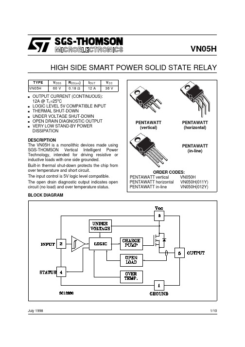
VN05H中文资料
VN05HHIGH SIDE SMART POWER SOLID STATE RELAYJuly 1998BLOCK DIAGRAMsOUTPUT CURRENT (CONTINUOUS):12A @ T c =25o Cs LOGIC LEVEL 5V COMPATIBLE INPUT s THERMAL SHUT-DOWNs UNDER VOLTAGE SHUT-DOWNs OPEN DRAIN DIAGNOSTIC OUTPUT sVERY LOW STAND-BY POWER DISSIPATIONDESCRIPTION The VN05H is a monolithic devices made using SGS-THOMSON Vertical Intelligent Power Technology, intended for driving resistive or inductive loads with one side grounded.Built-in thermal shut-down protects the chip from over temperature and short circuit.The input control is 5V logic level compatible.The open drain diagnostic output indicates open circuit (no load) and over temperature status.1/10VN05HABSOLUTE MAXIMUM RATINGCONNECTION DIAGRAMSCURRENT AND VOLTAGE CONVENTIONSVN05H THERMAL DATAELECTRICAL CHARACTERISTICS (V CC = 9 to 36 V; -40 ≤ T j≤ 125 o C unless otherwise specified) POWERSWITCHINGLOGIC INPUTELECTRICAL CHARACTERISTICS (Continued)PROTECTION AND DIAGNOSTICSexceed 10 mA at the input pin.(•) Status determinaion > 100 µs after the switching edge.Note 1: Above V CC = 36V the output voltage is clamped to 36V. Power dissipation increases and the device turns off it junction temperature reaches thermal shutdown temperature.FUNCTIONAL DESCRIPTIONThe device has a diagnostic output which indicates open circuit (no load) and over temperature conditions. The output signals are processed by internal logic.To protect the device against short circuit and over-current condition the thermal protection turns the integrated Power MOS off at a minimum junction temperature of 140 o C. When the temperature returns to about 125 o C the switch is automatically turned on again. To ensur the protection in all V CC conditions and in all the junction temperature range it is necessary to limit the voltage drop across Drain and Source (pin 3and 5) at 29 V. The device is able to withstand a load dump according the test pulse 5 at level III of the ISO TR/1 7631.Above V CC = 36V the output voltage is clamped to 36V. Power dissipation increases and the device turns off if junction temperature reaches thermal shutdown temperature.PROTECTING THE DEVICE AGAINST REVERSE BATTERYThe simplest way to protect the device against a continuous reverse battery voltage (-26V) is toinsert a Schottky diode between pin 1 (GND) and ground, as shown in the typical application circuit (fig. 3).The consequences of the voltage drop across this diode are as follows:-If the input is pulled to power GND, a negativevoltage of -V F is seen by the device. (V IL , V IH thresholds and V STAT are increased by V F with respect to power GND).-The undervoltage shutdown level is increasedby V F .If there is no need for the control unit to handle external analog signals referred to the power GND, the best approach is to connect the reference potential of the control unit to node [1](see application circuit infig. 4), which becomes the common signal GND for the whole control board.In this way no shift of V IH , V IL and V STAT takes place and no negative voltage appears on the INPUT pin; this solution allows the use of a standard diode, with a breakdown voltage able to handle any ISO normalized negative pulses thatoccours in the automotive environment.VN05HTRUTH TABLEFigure 1:WaveformsFigure 2:Over Current Test CircuitVN05HFigure 3:Typical Application Circuit With A Schottky Diode For Reverse Supply ProtectionFigure 4:Typical Application Circuit With Separate Signal GroundVN05HVN05HVN05HVN05HInformation furnished is believed to be accurate and reliable. However, STMicroelectronics assumes no responsibility for the consequences of use of such information nor for any infringement of patents or other rights of third parties which may result from its use. No license is granted by implication or otherwise under any patent or patent rights of STMicroelectronics. Specification mentioned in this publication are subject to change without notice. This publication supersedes and replaces all information previously supplied. STMicroelectronics products are not authorized for use as critical components in life support devices or systems without express written approval of STMicroelectronics.The ST logo is a trademark of STMicroelectronics © 1998 STMicroelectronics – Printed in Italy – All Rights ReservedSTMicroelectronics GROUP OF COMPANIESAustralia - Brazil - Canada - China - France - Germany - Italy - Japan - Korea - Malaysia - Malta - Mexico - Morocco - The Netherlands -Singapore - Spain - Sweden - Switzerland - Taiwan - Thailand - United Kingdom - U.S.A..VN05H。
绿色机器人科技模板

续时而生
LOGO-R系列
LOGO
云系列
产品功能:高亮照明灯,具有照明功能外观简洁,小巧,方便携带多个保护电子电路,保证设备的安全LED电量指标,电量随手掌握
产品参数:○ 型 号:R400/R600/R800/R1000○ 电 芯:国标锂离子○ 输 入:USB 5V / 1A○ 输 出:USB 5V / 1A○ 容 量:4400mAh/6600mAh /8800mAh/10000mAh
绿色机器人模板
高端科技来袭
R系列移动电源
2024新品解析
L心编制而成的,希望大家下载后,能够帮助大家解决实际问题。PPT课件下载后可定制修改,请根据实际需要进行调整和使用,谢谢!
本编为大家提供各种类型的PPT课件,如数学课件、语文课件、英语课件、地理课件、历史课件、政治课件、化学课件、物理课件等等,想了解不同课件格式和写法,敬请下载!
Moreover, our store provides various types of classic sample essays, such as contract agreements, documentary evidence, planning plans, summary reports, party and youth organization materials, reading notes, post reading reflections, essay encyclopedias, lesson plan materials, other sample essays, etc. If you want to learn about different formats and writing methods of sample essays, please stay tuned!
戴尔PowerEdgeR910
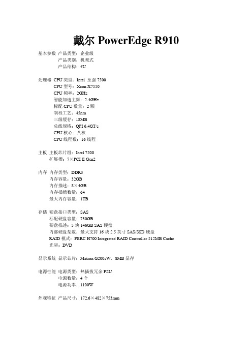
戴尔PowerEdge R910
基本参数产品类型:企业级
产品类别:机架式
产品结构:4U
处理器CPU类型:Intel 至强7500
CPU型号:Xeon X7550
CPU频率:2GHz
智能加速主频:2.4GHz
标配CPU数量:2颗
制程工艺:45nm
三级缓存:18MB
总线规格:QPI 6.4GT/s
CPU核心:八核
CPU线程数:16线程
主板主板芯片组:Intel 7500
扩展槽:7×PCI-E Gen2
内存内存类型:DDR3
内存容量:32GB
内存描述:8×4GB
内存插槽数量:64
最大内存容量:1TB
存储硬盘接口类型:SAS
标配硬盘容量:730GB
硬盘描述:5块146GB SAS硬盘
内部硬盘架数:最大支持16块2.5英寸SAS/SSD硬盘
RAID模式:PERC H700 Integrated RAID Controller 512MB Cache
光驱:DVD
显示系统显示芯片:Matrox G200eW,8MB显存
电源性能电源类型:热插拔冗余PSU
电源数量:4个
电源功率:1100W
外观特征产品尺寸:172.6×482×753mm。
惠普 Presario 5000系列系统板和处理器 spare part 部件清单说明书

System/ProcessorBoards Assembly Spare Part SystemSystem Board, Processor320460-102320756-0015010, 15ED, 20, 23,30, 34ES, 35, 37 System Board, Processor320460-001320725-0015010, 20, 30, 50,55ES, 70, 72, 75 System Board108846-0015070386021-0015060 (EMEA only) System Board, w/o AMDProcessor320446-101320645-0015050, 60, 62, 70, 75 Processor Board, 4 MBN+FPProcessor, w/ M Chip320460-105381338-0015050, 57320460-106330641-0015050Processor, w/ M Chip, w/oNIC, w/o FP, 4 MBProcessor, w/ FP w/ NIC320460-103329089-0015050Processor, w/ FP, w/o NIC320458-102329090-0015056Configuration Jumper Settings (Models 5010 - 5020)Jumper Pins Function1,2233 MHz Processor FrequencyP1 - P4 ProcessorFrequency Select for 66MHz Bus Frequency3266 MHz Processor Frequency1,3300 MHz Processor Frequency2,4333 MHz Processor FrequencyP22 CMOS Clear1-2*Secure CMOS PowerOpen Remove jumper for 10 sec, reinstall toclear CMOS* DefaultConfiguration Jumper Settings (Models 5030 - 5075)Jumper Pins Function2200** MHz Processor FrequencyP1 - P4 ProcessorFrequency Select for 66MHz Bus Frequency1,2233** MHz Processor Frequency3266 MHz Processor Frequency1,3300 MHz Processor Frequency2,3333 MHz Processor FrequencyP1-P4 Processor Frequency2300** MHz Processor Frequency Select with 100 MHz BusFrequency1,2350 MHz Processor Frequency3400 MHz Processor Frequency1,3450 MHz Processor Frequency2,3500** MHz Processor FrequencyP22 CMOS Clear1-2*Secure CMOS PowerOpen Remove jumper for 10 sec, reinstall toclear CMOS* Default** Not shipped in these configurations.Jumper Settings, 66 MHzFrequency (MHz)200233266300333 JP1OFF ON OFF ON OFF JP2ON ON OFF OFF ON JP3OFF OFF ON ON ON JP4OFF OFF OFF OFF OFF Jumper Settings, 100 MHzFrequency (MHz)300350400450500 JP1OFF ON OFF ON OFF JP2ON ON OFF OFF ON JP3OFF OFF ON ON ON JP4OFF OFF OFF OFF OFF Memory SIMMs Assembly Spare Part System48 MB Memory Module 278030-002320673-0015010, 15ED, 15,20, 23, 30, 34ES,50, 55ES48 MB MemoryModule278030-002278066-0015050, 60, 62, 70 64 MB MemoryModule278031-002179190-0015010, 20, 30, 70Memory DIMMs Assembly Spare Part System16 MB, 100 MHz178923-001166969-001505616 MB, 66 MHz286547-001278066-0015050, 5732 MB, 66 MHz286548-101341717-0015050, 5732 MB, 100 MHz320767-101319326-0015034ES, 5632 MB, 100 MHz323029-001337372-001507064 MB, 66 MHz320747-101320669-0015020, 30, 32, 35,37, 38, 50, 70,72, 7564 MB, 100 MHz320768-101320670-0015010, 20, 30, 60,70Microprocessor Assembly Spare Part System Pentium-II/266332811-001332858-0015020Pentium-II/300270848-007328413-0015030, 32, 34ES,35, 37, 38C2/300341718-0015020, 5023C2/266341719-0015010, 5015 300320471-002320647-0015070333 MHz CII316356-002330648-0015050, 56, 57 333 MHz K6II320471-003337364-0015050, 55ES, 60,62, 70, 75 350278309-001327583-0015060350, K6-2330631-002388241-0015070ConfigurationCode Assembly System BoardSpare Part ModelBSV6320460-102320756-0015015EDBX23320460-101320446-101320725-001320645-0015075BX24320460-101320446-101320725-001320645-0015070BX26320460-101320725-0015072BX27320460-101320446-101320725-001320645-0015070BX28320460-101320446-101320725-001320645-0015070BX29320460-101320446-101320725-001320645-0015070BX2C320460-101320446-101320725-001320645-0015070BXV2320460-102320460-101320756-001320725-0015010BXV3320460-102320460-101320756-001320725-0015010BXV4320460-102320460-101320756-001320725-0015010BXV5320460-102320460-101320756-001320725-0015010BXV7320460-102320460-101320756-001320725-0015010BXVB320460-102320460-101320756-001320725-0015010BXVC320460-102320756-0015015BXZ2320460-101320446-101320725-001320645-0015050BXZ2320446-101320645-0015062BXZ3320460-101320446-101320725-001320645-001380621-0015050, 60BXZ4320460-101320446-101320725-001320645-0015050, 60BXZ5320460-101320446-101320725-001320645-0015050BXZ6320460-101320446-101320725-001320645-0015050, 60BXZ7320460-101320725-0015055ESBXZC320460-101320446-101320725-001320645-0015050BY3B320460-102320460-101320756-001320725-0015030BY3C320460-102320460-101320756-001320725-0015030BY3G320460-102320460-101320756-001320725-0015030BY3H320460-102320756-0015034ES BY3K320460-102320756-0015034ESBYF2320460-101320446-101320725-001320645-0015050BYF4320460-101320446-101320725-001320645-0015050BYF5320458-102329090-0015056ContinuedConfigurationCode Assembly System BoardSpare Part ModelBY3Q320460-101320725-0015032 BY3X320460-101320725-0015032BY32320460-102320460-101320756-001320725-0015030BY33320460-102320460-101320756-001320725-0015030BY34320460-102320756-0015035BY35320460-102320460-101320756-001320725-0015030BY37320460-102320460-101320756-001320725-0015030BY37320460-101320725-0015032BY38320460-102320460-101320756-001320725-0015030CCH2320460-102320460-101320756-001320725-0015020CCH3320460-102320460-101320756-001320725-0015020CCH4320460-102320460-101320756-001320725-0015020CCH5320460-102320460-101320756-001320725-0015020CCH6320460-102320460-101320756-001320725-0015020CCH7320460-102320460-101320756-001320725-0015020CCH8320460-102320460-101320756-001320725-0015020CCH9320460-102320460-101320756-001320725-0015020CMN2108846-0015070CNM7108846-0015070Hard Drives Assembly Spare Part System3.2 GB, IDE286114-001286538-0015010, 204 GB, IDE286119-001320648-0015010, 15ED, 20,30, 50, 604 GB, IDE337379-00150706.0 GB, IDE286556-001271127-0015010, 15, 20, 23,30, 34ES, 37, 50,55ES, 60, 62, 70 6.0 GB, IDE286556-001298463-00150568.0 GB, IDE286123-001298464-0015035, 50, 57, 60,62, 7012.0 GB, IDE286466-405298465-0015075CD-ROM Drives Assembly Spare Part SystemCD-ROM, IDE, 32X298520-005317212-001All except 5055ES,70, 72, 75CD-ROM, IDE, 32X298520-006317212-0015050, 60, 62CD-ROM, IDE, 32X310185-001317212-0015056, 70DVD2286466-405317213-001DVD3320716-401327446-0015050, 55ES, 60,70, 72, 75Diskette Drives Assembly Spare Part System1.44 MB141087-406304337-001304235-001All1.44 MB239612-4015070Zip270988-002270946-0015030, 32, 35, 72 56K ModemCountry Assembly Spare Part CableSpare Part SystemAPD292256-003292269-003165224-0015010, 20, 30, 50 APD007201-003317296-0015060Brazil292256-003292269-0035020Canada292256-003292269-0035030, 35, 50 Caribbean292256-003292269-0035020, 50 EMEA007201-003317296-0015060Italy165224-062165224-0625060Japan292256-003292269-0035010, 15ED, 20,30, 50, 70Latin America292256-003292269-003165224-0015020, 50New Zealand165224-033165224-0335060Portugal292256-003292269-003165224-1315030, 50 Portugal112666-005165224-1315060Spain292256-003292269-003304398-0715020, 30Spain112666-005304398-0715060Taiwan292256-003292269-0035010, 30 UnitedKingdom165227-033165224-0335060United States292256-003292269-0035015ED, 30,34ES, 35, 50,72Z-56K ModemCountry Assembly Spare Part CableSpare Part SystemAustralia007201-003317296-001165224-0125010, 15ED, 20,30, 50, 60, 70 Belgium007201-003317296-001304398-1815010, 20, 30,50, 56, 60, 70 Brazil292256-003317297-0015010, 20, 50 Canada292256-003317297-0015010, 30, 35, 37 Canada337550-001337559-0015057 Caribbean292256-003317297-0015010, 20, 23, 50 Denmark007201-003317296-001304398-0815010, 20, 30,50, 60, 70 Finland007201-003317296-001304398-3515010, 30, 50,60, 70France007201-003317296-001304398-0515010, 20, 30,50, 60, 70 Germany007201-003317296-001290663-0015020, 30, 60 Italy007201-003317296-001165224-0625010, 20, 30,50, 60, 70 Japan292256-003292269-0035010, 20, 30,50, 70Japan337550-001337559-0015050Korea007201-003317296-0015010, 30, 60 Latin America292256-003317297-001165224-0015010, 20, 23, 50 LatinAmerica/Brazilmfg.292256-003317297-0015010, 20, 23, 50ContinuedZ-56K ModemCountry Assembly Spare Part CableSpare Part SystemNetherlands007201-003317296-001304398-3315010, 20, 30,50, 60, 70New Zealand007201-003317296-001165224-0335010, 20, 30,50, 60, 70 Norway007201-003317296-001304398-0915010, 20, 30,50, 60, 70 Portugal292256-003317297-001165224-1315030, 50, 70 Puerto Rico292256-003317297-001165224-0125010, 50Spain292256-003317297-001304398-0715020, 30, 50, 70 Sweden007201-003317296-001304398-1015010, 20, 30,50, 60, 70 Switzerland007201-003317296-001304398-1115010, 20, 30,50, 60, 70 Taiwan292256-003317297-0025010, 20, 30U Kingdom007201-003317296-001165224-0335010, 20, 30,50, 60, 70 United States -Education292256-002292269-0025015ED, 34ES United States -Retail337550-001337559-0015057, 70United States -Retail 292256-002292269-0025010, 15, 30,35, 50, 72, 75Cable Information Assembly Spare Part Modem Cable - POR112666-005165224-131 Modem Cable - SPAIN112666-005304398-101 Modem Cable - PR165224-012165224-012 Modem Cable - NZ165224-033165224-033 Modem Cable - UK165227-033165224-033 Modem Cable - NA112666-003137256-001 Modem Cable - ITALY165227-062165224-062 Modem Cable Adapter- Aus/NZ112666-005304398-011 Modem Cable Adapter- BEL112666-005304398-181 Modem Cable Adapter- FR112666-005304398-051 Modem Cable Adapter- DK112666-005304398-081 Modem Cable Adapter- NOR112666-005304398-091 Modem Cable Adapter- SWE112666-005304398-101 Modem Cable Adapter- SWI112666-005304398-111 Modem Cable Adapter- NL112666-005304398-331 Modem Cable Adapter- FIN112666-005304398-351 Modem Cable Adapter- IT112666-005304398-061 Cable Kit320560-001310187-001320561-001310188-002298486-001320558-001320663-001Cable Kit (5056)320560-001310187-001320561-001310188-002298486-001320558-001170720-001Miscellaneous Assembly Spare Part Keyboard, US340740-003340869-003 Keyboard, US Education286220-003304242-001 Mouse, Ivory149998-006199181-401 Mouse, Ivory (5070)141649-008337416-001 Button Board w/ Bracket308882-002320664-001 Chassis Fan (5070)298582-003298474-001Controller Boards Assembly Spare Part PCI, 10/100317607-001317606-001 PCI, 10/100, w/ TX (5070)122849-001123494-001Power Supply/Battery Assembly Spare Part319239-002319235-001 Power Supply, 110W (model 5050, 56, 57, 60, 62,70)Battery (5070)234556-001Memory Upgrade ChartPROCESSOR BOARD320460-001A MAXIMUM OF 256 MB TOTAL MEMORYMEMORY OPTIONS ARE NOT AVAILABE FOR THE PRESARIO 5000 SERIESPresario 5070Memory Upgrade ChartSYSTEM BOARD108846-001MAXIMUM MEMORY 384MBNO MEMORY OPTIONS AVAILABLE。
amd全线服务器CPU参数
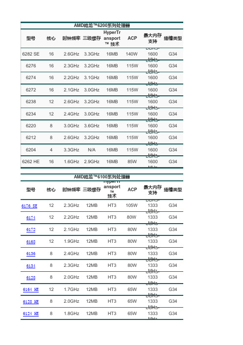
最大内存 插槽类型 支持 DDR31600 MHz DDR31600 MHz DDR31600 MHz DDR31600 MHz DDR31600 MHz DDR31600 MHz DDR31600 MHz DDR31600 MHz
4284 4280 4238 4234 4226 4274 HE 4228 HE 4256 EE
4184 4180 4130 4122 4176 HE 4174 HE 4170 HE 4164 EE 4162 EE
6存 插槽类型 支持 DDR31333 MHz DDR31333 MHz DDR31333 MHz DDR31333 MHz DDR31333 MHz DDR31333 MHz DDR31333 MHz DDR31333 MHz DDR31333 MHz DDR31333 MHz G34 G34 G34 G34 G34 G34 G34 G34 G34 G34
8 8 6 6 6 8 6 8
C32 C32 C32 C32 C32 C32 C32 C32
型号
核心
AMD皓龙 皓龙™4100系列处理器 皓龙 系列处理器 HyperTr ACP 时钟频率 三级缓存 ansport ™ 技术 2.8GHz 2.6GHz 2.6GHz 2.2GHz 2.4GHz 2.3GHz 2.1GHz 1.8GHz 1.7GHz 6MB 6MB 6MB 6MB 6MB 6MB 6MB 6MB 6MB HT3 HT3 HT3 HT3 HT3 HT3 HT3 HT3 HT3 75W 75W 75W 75W 50W 50W 50W 32W 32W
6176 SE 6174 6172 6168 6136 6134 6128 6164 HE 6128 HE 6124 HE
5510说明书

4.7、安装附着装置……………………………………………………………40
4.8、塔机接地设施……………………………………………………………44
五、电器控制与操纵系统……………………………………………………44
5.1、塔机的操作………………………………………………………………45
6.3、各种安全装置的调整……………………………………………………51
七、塔机的使用与维护保养…………………………………………………56
7.1、塔机的安全使用须知……………………………………………………56
7.2、塔机的维护保养…………………………………………………………57
7.3、塔机的工作条件和工作环境……………………………………………59
30
28.51
26.30
28.51
26.3
24.37
21.89
19.8
起重幅度(m)
40
42
45
起重量
(KN)
a=4
18.58
17.47
16
a=2
18.58
17.47
16
表1.5
注意:为了保证塔机安全,塔吊司机应严格按照载荷特性表中的数据起吊重物。
二.塔机机构的构造及特点(其主要参数阅表1.1、表1.2)
①工作中严禁长时间使用低速,连续使用低速不得超过1.5分钟,否则将烧坏电机。
②额定起重量严禁使用高速,高速只能用于空钩升降或额定重量的1/2,否则也将会烧坏电机。
2.2变幅机构(参图2.3)
2~13.62
15
18
20
22
25
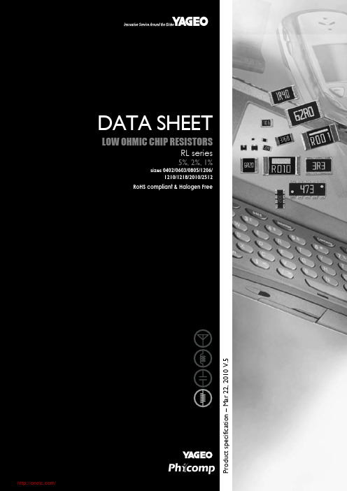
RL0805FR-070R51L;RL2512FK-07R018L;RL0805JR-070R22L;RL0402FR-070R68L;中文规格书,Datasheet资料
-
-
LPRC201 2322 ±1% 0.01 to 1 Ω 735 7xxxx
-
-
2010 LPRC111 2322 ±5% 0.01 to 0.0976 Ω 760 90xxx
-
-
LPRC111 2322 ±5% 0.1 to 1 Ω
760 60xxx
-
-
LPRC111 2322 ±1% 0.01 to 0.0976 Ω 761 90xxx
APPLICATIONS Converters Printer equipment Server board Telecom Consumer
FEATURES Halogen Free Epoxy RoHS compliant - Products with lead free terminations meet RoHS requirements - Pb-glass contained in electrodes, resistor element and glass are exempted by RoHS Reducing environmentally hazardous wastes High component and equipment reliability Saving of PCB space None forbidden-materials used in products/production Low resistances applied to current sensing
-
-
LPRC111 2322 ±1% 0.1 to 1 Ω
761 6xxxx
-
-
2512 LPRC221 2322 ±5% 0.01 to 0.0976 Ω 762 90xxx
SMH-50 50 50-150-XL 硬體操作說明書说明书

SMH-50/50/50-150-XL 硬体操作说明书匯出日期:2023-10-19修改日期:2021-04-19•••••••••••••••••••••••目录序言适用机型硬体规格说明外观介绍外形尺寸驱动器规格搬运与安装搬运安装环境条件与注意事项配线与信号周边装置接线图驱动器的连接器与端子说明各式配线图串列向量配线图新代编码器外接类比温感配线图多台四合一串联说明回生电阻选用简易回生电阻选择详细回生电阻选择KTY84温感器与过温度保护功能安装驱动器参数设定版本号编修日期编修内容作者审查核准V1.22022-6-30修正为SMD-34B-50150-xx 硬体操作说明书带电池盒乃维V1.12020-7-23刪去電容吸收能量Ec黃揚程V1.02018/10/04新增SMD-34B-50150-xx 硬体操作说明书杨娟HomePageSYNTEC伺服操作说明书文件资讯文件履历文件资讯文件履历1 序言感谢您长期对本公司产品的使用与支持。
本公司伺服团队不断致力於各项产品的研发,期许本公司产品与服务能给使用者带来最大的效益。
新代高性能驱动器系列产品为本公司最新推出之伺服驱动器,本产品使用高品质之元件与材料,并经过严格测试,采用精密向量控制,具有高精确度、高稳定性、高效率之特性。
本使用说明内容包括驱动器的硬体规格、安装、配线与讯号,能提供给使用者最正确的指引与操作,为充分发挥产品应有的优异性能与维护人员及设备的安全,在使用前请详细阅读本使用手册,并且妥善保存,以备日後调校与保养时使用,若有任何疑虑,请与本公司联络,本公司专业人员将竭诚为您服务。
2 适用机型本操作手册适用於新代 3KWX3+18.5KW四合一驱动器3 硬体规格3.1 说明每部驱动器在出厂前均经过详细品管检查与防撞包装处理,请使用者收到产品後应先检查外观有无撞击损伤,并将外盒与产品上之序号做比对是否一致,若有不符,请第一时间与本公司联络。
型号说明3.2 外观介绍SMH-50/50/50-150-XL驱动器功能模块说明A外供电源输入接点连接380V~440V三相交流电(RST) B马达驱动电源输出接点连接马达侧提供马达电源(UVW)由右至左分别为第一至第四轴C煞车电阻接点煞车电阻接点(P-B)D MIII串行通讯接孔连接上位控制器(MIII讯号)连接串行驱动器 (MIII讯号) E Mini USB接孔连接个人计算机调机使用F I/O讯号端口外接电池端口连接I/O设备(急停、警示灯…等)连接绝对型编码器供电电池G STO讯号端口STO接口,2组安全输入,1组安全功能回授H编码器回授接孔由上至下分别为第一至第四埠。
