Dynamic maintenance of molecular surfaces under conformational changes
动态高压微射流处理对低盐肌原纤维蛋白溶解度和结构的影响

动态高压微射流处理对低盐肌原纤维蛋白溶解度和结构的影响吴佳;赵鸾;魏娜;赵磊;王立宇;夏杨毅【期刊名称】《食品与发酵工业》【年(卷),期】2022(48)11【摘要】探讨了动态高压微射流(dynamic high pressure microfluidization,DHPM)处理压力(0、34、69、103、138、172 MPa)和处理次数(0~12次)对低盐(0.15 mol/L NaCl)肌原纤维蛋白溶解度和结构的影响。
结果表明,随着DHPM处理压力和次数的增加(P<0.05),蛋白溶解度显著增加(P<0.05),但103 MPa后不再显著(P>0.05)、Zeta-粒径显著降低(P<0.05)。
蛋白表面疏水性经DHPM处理后显著增加(P<0.05),但其随着压力的增加显著降低(P<0.05),随着次数的增加先增加后降低(P<0.05),这是蛋白结构展开又折叠的结果。
经DHPM 处理后,激光共聚焦显微镜显示蛋白颗粒变小、尺寸均匀;十二烷基硫酸钠-聚丙烯酰氨凝胶电泳显示蛋白发生了降解;拉曼分析显示α-螺旋含量明显下降,无规则卷曲含量增加。
综上,DHPM处理能破碎蛋白,使蛋白解聚、尺寸变小,结构发生改变,进而改善低盐下肌原纤维蛋白的溶解度。
【总页数】7页(P129-135)【作者】吴佳;赵鸾;魏娜;赵磊;王立宇;夏杨毅【作者单位】西南大学食品科学学院;重庆市特色食品工程技术研究中心【正文语种】中文【中图分类】TS2【相关文献】1.动态高压微射流协同美拉德反应对α-乳白蛋白结构和功能性质的影响2.动态高压微射流协同糖基化对β-乳球蛋白乳化性和结构的影响3.动态高压微射流技术对乳清蛋白结构的影响4.动态高压微射流协同糖基化处理对β-乳球蛋白热稳定性和结构的影响5.动态高压微射流处理顺序对果胶-乳铁蛋白复合物结构及性质的影响因版权原因,仅展示原文概要,查看原文内容请购买。
当表面活性剂遇到大环分子

114Univ. Chem. 2023, 38 (12), 114–119收稿:2023-06-27;录用:2023-08-01;网络发表:2023-08-11*通讯作者,Email:*****************.cn基金资助:2021年基础学科拔尖学生培养计划2.0研究课题(20211014);天津市首批虚拟教研室试点建设项目(化学类交叉人才培养课程建设虚拟教研室)•专题• doi: 10.3866/PKU.DXHX202306051 当表面活性剂遇到大环分子阮文娟,李悦,耿文超,郭东升*南开大学化学学院,天津 300071摘要:近年来,表面和胶体化学与大环化学的结合引起了科学家的普遍关注。
将多样的大环结构引入表面活性剂分子,不仅极大地丰富了表面活性剂分子的种类,还可以赋予其大环的主客体识别功能。
由此所开发出的大环两亲和超两亲分子已在生物成像和药物递送中表现出很高的应用潜力。
从传统表面活性剂到大环两亲和超两亲分子的发展、应用表明,不同领域的交叉融合对科学研究的发展是非常重要的。
关键词:表面活性剂;胶束;大环结构;大环两亲分子;超两亲分子中图分类号:G64;O6Encountering of Surfactants with Macrocyclic MoleculesWen-Juan Ruan, Yue Li, Wen-Chao Geng, Dong-Sheng Guo *College of Chemistry, Nankai University, Tianjin 300071, China.Abstract: In recent years, the combination of surface and colloid chemistry with macrocyclic chemistry has garnered widespread attention among scientists. The integration of diverse macrocyclic structures into surfactant molecules not only greatly enriches the diversity of surfactants, but also imparts them with the host-guest recognition functionality of macrocycles. Macrocyclic amphiphiles and supra-amphiphiles, developed from this approach, have demonstrated high potential in applications such as bioimaging and drug delivery. The evolution from traditional surfactants to macrocyclic amphiphiles and supra-amphiphiles underscores the importance of interdisciplinary integration in advancing scientific research.Key Words: Surfactants; Micelles; Macrocycles; Macrocyclic amphiphiles; Supra-amphiphiles表面活性剂及其所构筑的胶束是表面和胶体化学中所涉及的一类非常重要的体系。
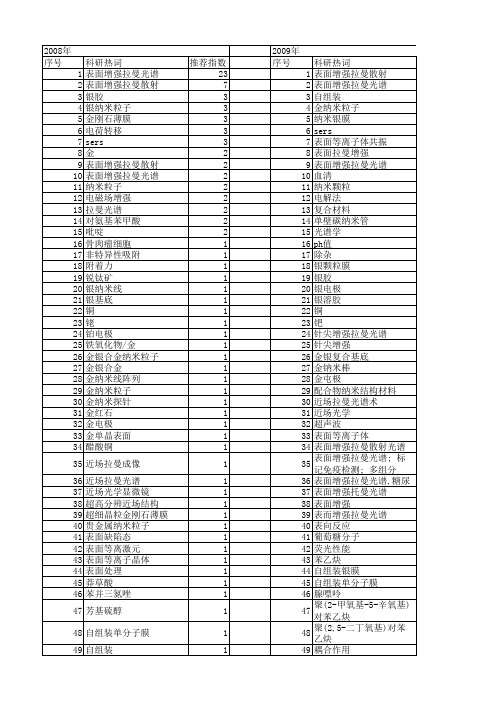
【国家自然科学基金】_表面增强拉曼_基金支持热词逐年推荐_【万方软件创新助手】_20140730
53 54 55 56 57 58 59 60 61 62 63 64 65 66 67 68 69 70 71 72 73 74 75 76 77 78 79 80 81 82 83 84 85 86 87 88 89 90 91 92 93 94 95 96 97 98 99 100 101 102 103 104 105 106
科研热词 推荐指数 表面增强拉曼光谱 23 表面增强拉曼散射 7 银胶 3 银纳米粒子 3 金刚石薄膜 3 电荷转移 3 sers 3 金 2 表面增强拉曼散射(sers) 2 表面增强拉曼光谱(sers) 2 纳米粒子 2 电磁场增强 2 拉曼光谱 2 对氨基苯甲酸 2 吡啶 2 骨肉瘤细胞 1 非特异性吸附 1 附着力 1 锐钛矿 1 银纳米线 1 银基底 1 铜 1 铑 1 铂电极 1 铁氧化物/金 1 金银合金纳米粒子 1 金银合金 1 金纳米线阵列 1 金纳米粒子 1 金纳米探针 1 金红石 1 金电极 1 金单晶表面 1 醋酸铜 1 近场拉曼成像 1 近场拉曼光谱 1 近场光学显微镜 1 超高分辨近场结构 1 超细晶粒金刚石薄膜 1 贵金属纳米粒子 1 表面缺陷态 1 表面等离激元 1 表面等离子晶体 1 表面处理 1 莽草酸 1 苯并三氮唑 1 芳基硫醇 1 自组装单分子膜 1 自组装 1 脱金属硫蛋白 1 脉冲激光沉积法 1 脉冲激光沉积 1
聚苯乙烯微球 聚吡咯 缓冲层 维生素pp 统一理论 结晶度 细胞成分 细胞凋亡 纳米钛酸锶颗粒 纳米金 纳米药物载体 纳米粒子有序膜 纳米空球 纳米光束流 红外光谱 紫外拉曼光谱 粗糙表面 穿膜机制 离子液体 离子吸附 磁性核壳纳米粒子 碳纳米管 碳纤维/环氧复合材料界面 硼掺杂 硬质合金 硫氰根 直流磁控溅射 电荷转移. 电氧化 电场局域化 电化学沉积 电催化氧化 甲醇 甲酸 琉基吡啶 现场电化学紫外-可见吸收光谱 物理增强机理 热丝化学气相沉积 灵敏度 激光刻蚀 核壳结构 标记免疫 晶粒间界 晶粒 晶格扩张 摩擦磨损性能 拉曼显微成像 扫描近场光学显微术 微极化区 对巯基苯胺 孔雀石绿分子 孔雀石绿 多组分检测 复杂形状刀具
构筑星形化合物提升交联网络固态聚合物电解质性能

构筑星形化合物提升交联网络固态聚合物电解质性能王万慧;王春娟;胡骥【期刊名称】《华南师范大学学报(自然科学版)》【年(卷),期】2024(56)2【摘要】通过巯基-丙烯酸酯点击反应引发三羟甲基丙烷三(3-巯基丙酸酯)(TMPMP)或季戊四醇四-3-巯基丙酸酯(PETMP)分别与聚(乙二醇)甲基丙烯酸酯(PEGMA)进行UV辐照反应,制得星型化合物。
TMPMP或PETMP为交联剂,PEGMA为星形化合物的支链。
星形化合物的结构可通过变换不同的交联剂,并通过改变PEGMA的相对分子质量进行调节。
将星形化合物掺入交联固态聚合物电解质中,固态电解质的机械性能、电化学性能均得到改善。
固态电解质的拉伸强度达83.9 MPa,杨氏模量达180.4 MPa,断裂伸长率达49.9%,拉伸韧性达22.6 MJ/m^(3),室温离子电导率达2.8×10^(-5) S/cm。
利用该固态电解质组装Li/LFP 全固态锂金属电池,在0.1 C倍率下循环100次后剩余比容量为111.5 mAh/g,比容量保持率为77%。
【总页数】7页(P25-31)【作者】王万慧;王春娟;胡骥【作者单位】洛阳理工学院材料科学与工程学院;河南省太阳能转换及锂钠基储能电池材料国际联合实验室;河南省建筑型材智能制造工程技术研究中心【正文语种】中文【中图分类】O633.2【相关文献】1.一种嵌段星形凝胶聚合物电解质的制备与性能2.含烷氧磺酸锂盐及对称星形醚的聚环氧乙烷基聚合物电解质的制备及电化学性能3.固态聚合物电解质性能提升方法的研究进展4.高性能阻燃PEO固态聚合物电解质的制备与性能5.石榴石型固态电解质/铝锂合金界面构筑及电化学性能因版权原因,仅展示原文概要,查看原文内容请购买。
超疏水涂层防覆冰技术研究进展

㊀第43卷㊀第4期2024年4月中国材料进展MATERIALS CHINAVol.43㊀No.4Apr.2024收稿日期:2022-04-23㊀㊀修回日期:2022-07-15基金项目:新疆维吾尔自治区自然科学青年基金项目(2021D01C100);天山青年计划项目(2020Q012);天池百人计划项目(TCBR202106)第一作者:陈小东,男,1997年生,硕士研究生通讯作者:胡丽娜,女,1986年生,副教授,硕士生导师,Email:hulina@DOI :10.7502/j.issn.1674-3962.202204022超疏水涂层防覆冰技术研究进展陈小东,胡丽娜,杜一枝(新疆大学电气工程学院,新疆乌鲁木齐830017)摘㊀要:覆冰现象时刻威胁着电力系统的安全运行,过去几十年里,研究人员采用各种措施来预防电力设备表面覆冰,但这些措施都无法从根本上解决该问题㊂超疏水涂层由于具有独特的微纳米结构及低表面能物质,在低温环境下,能够延缓结冰且降低表面的冰附着力㊂从超疏水涂层的防覆冰机理入手,重点综述国内外超疏水涂层防覆冰的实验研究现状,并将影响防覆冰性能的因素分为环境因素和基底因素,分析当前方案的局限性,同时阐述提高超疏水涂层机械鲁棒性的设计与制备方面的最新进展,最后提出超疏水涂层在电力系统应用中存在的问题以及未来的发展方向㊂该综述有助于研究人员建立评估超疏水涂层的防覆冰性能的试验规范,并推进超疏水涂层防覆冰技术在电力系统中的应用㊂关键词:电力系统;超疏水涂层;防覆冰机理;环境因素;基底因素中图分类号:TG174.4㊀㊀文献标识码:A㊀㊀文章编号:1674-3962(2024)04-0301-10引用格式:陈小东,胡丽娜,杜一枝.超疏水涂层防覆冰技术研究进展[J].中国材料进展,2024,43(4):301-310.CHEN X D,HU L N,DU Y Z.Research Progress of Anti-Icing Technology of Superhydrophobic Coating[J].Materials China,2024,43(4):301-310.Research Progress of Anti-Icing Technology ofSuperhydrophobic CoatingCHEN Xiaodong,HU Lina,DU Yizhi(School of Electrical Engineering,Xinjiang University,Urumqi 830017,China)Abstract :Icing always threatens the safe operation of power system.In the past few decades,researchers have taken vari-ous measures to prevent the icing on the surface of power equipments,but these measures can not fundamentally solve this problem.Due to its unique micro-nano structure and low surface energy materials,superhydrophobic coating can delay icing and reduce the adhesion ability of surface ice at low temperature.Therefore,started with the anti-icing mechanism of super-hydrophobic coating,this paper focuses on the experimental research status of anti-icing of superhydrophobic coating at home and abroad,divides the factors affecting the anti-icing performance into environmental factors and substrate factors,analyzes the limitations of the current schemes,and expounds the latest design and preparation progress on improving the mechanical robustness of superhydrophobic coating.Finally,the problems existing in the application of superhydrophobic coating in pow-er system and the future development direction are put forward.This review is helpful for researchers to establish test specifi-cations for evaluating the anti-icing performance of superhydrophobic coatings and promote their application in power system.Key words :power system;superhydrophobic coating;anti-icing mechanism;environmental factors;substrate factors1㊀前㊀言随着特高压直流输电技术的突破和新能源并网需求的增多,电力设备数量激增,设备表面凝露[1,2]㊁覆冰现象降低了电网供电能力,给电网的检修维护提出巨大挑战㊂在国内外学者的不断探索下,目前主要有2种思路来应对电力设备的防覆冰问题:除冰和防冰[3,4]㊂除冰方法包括:机械除冰法[5,6]㊁热力除冰法[7-9]㊁电磁除冰法和超声波除冰法[10]㊁化学除冰法[11,12]㊂防冰方法包括被动除冰法以及其它方法[13]㊂被动除冰方法是指涂覆电热防冰材料[14,15]和光热防冰材料[16,17],这种方法会导致电线中有泄露电流,且增加线路损耗㊂近10年来,随着仿生涂层材料的发展[18],研究人员从单一的除冰或防中国材料进展第43卷冰开始走向 防-除并举 ,着重于防㊂受 荷叶效应 启发,1996年Onda等[19]在玻璃板上用烷基烯二聚体制备粗糙表面,并在其上涂覆低表面能材料,首次获得了人工超疏水表面,为超疏水涂层的制备提供重要思路㊂该涂层使液滴难以附着于表面,在很大程度上减少了表面结冰概率和结冰量㊂图1列举了自然界中超疏水涂层的例子[20-23]㊂全力挖掘超疏水涂层在防覆冰领域的潜力,对我国 双碳 目标的实现具有重大意义㊂图1㊀自然界中超疏水涂层的例子:(a)莲叶[20],(b)鼠尾草表面[21],(c)蝴蝶翅膀[22],(d)壁虎足底[23] Fig.1㊀Examples of superhydrophobic coatings in nature:(a)lotus leaf[20],(b)sage surface[21],(c)butterfly wings[22],(d) gecko foot[23]㊀㊀目前研究现状表明,还没有一种材料可以完全解决如低温高湿等的复杂环境中的积冰问题,现有关于超疏水涂层的研究多数处于实验室阶段㊂因此,本文从超疏水涂层的防覆冰机理着手,重点综述超疏水涂层防覆冰性能的主要影响因素,探讨与工程实际应用环境的差距,总结当前设计方案的局限,同时针对超疏水涂层机械稳定性差这一问题,阐述提高涂层鲁棒性的设计与制备方法的最新进展㊂本综述希望为适应复杂环境的超疏水涂层的设计提供支撑,加快工业化进程㊂2㊀超疏水涂层防覆冰机理表面结冰从宏观上可分为3个阶段:首先是水蒸气或小液滴在冷表面凝结;其次是过冷液滴结冰;最后是液滴完全冻结,固态冰继续增长[24,25]㊂超疏水涂层的防覆冰机理可从3个方面阐释:一是超疏水涂层表面的过冷液滴滑落[26];二是超疏水涂层表面可延缓液滴结冰过程[27,28];三是超疏水涂层的低表面能可降低冰与基底的粘附力[29,30]㊂2.1㊀过冷液滴滑落超疏水涂层具有微纳米粗糙结构及低表面能物质,液滴在表面呈Cassie-Baxter状态[31],此状态下,液滴与表面粗糙结构之间存在 空气垫 ,这些空气垫起到 托举 作用,减小了液滴与表面的接触面积㊂相较于亲水和疏水表面,当液滴撞击到超疏水表面或液滴受到外力时,在-25ħ左右液滴出现明显的收缩和反弹行为[32],且最大限度地缩短过冷水与表面的接触时间㊂但是在高湿度㊁接近露点温度时,超疏水表面的接触角降低,滚动角增加,这种液滴的弹跳效应可能无效[33],因此在表面试验时,要仔细考虑环境因素㊂除了 空气垫 作用,冷凝形成的小水珠在超疏水涂层纳米结构的毛细管力作用下逃逸出纳米间隙,随后与其他水珠结合成小水滴,该过程释放的能量使得水滴发生自迁移[34]㊂由于 空气垫 作用和自迁移现象,液滴在结冰之前会从超疏水表面滑落,从而大大降低表面的结冰概率和结冰量㊂图2为液滴在超疏水表面的各种状态㊂图2㊀液滴在超疏水表面的各种可能状态:(a)Cassie-Baxter状态,(b)液滴在表面滑落,(c)液滴弹跳Fig.2㊀Possible states of droplets on superhydrophobic coatings:(a)Cassie-Baxter state,(b)droplets sliding on the surface,(c)droplet bouncing2.2㊀延缓结冰时间经典成核理论中,均相成核能垒由式(1)计算: 203㊀第4期陈小东等:超疏水涂层防覆冰技术研究进展ΔGhomo c=16πγ33(ΔG V )2(1)式中,γ为冰和水的界面张力,ΔG V 为单位体积冰和水的自由能之差㊂考虑到外界因素对成核的促进作用,此时结冰为异相成核过程,成核能垒为[35]:ΔG c =ΔGhomo cf (m ,x )(2)式(2)中,系数f (m ,x )取值在0到1之间㊂对于表面的结冰现象,在一定的驱动力下,主要考虑表面形貌对成核能垒的影响[35],即:f (m ,x )=12+121-mx w ()+x 322-3x -m w ()+(x -m )3w éëêùûú+3mx 32x -m w -1()(3)式(3)中,w =(1+x 2-2xm )1/2,m =cos θ,x =r /r c ,θ为冰核与表面的接触角,r 为成核促进粒子半径,r c 为结冰的临界成核半径㊂研究表明,在一定的驱动力下,液滴在凸面成核时,基底曲率半径越小,成核能垒越高;而在凹面成核时,刚好相反[36,37]㊂最近,作者课题组最新研究成果也证实了这一点[38]㊂除此之外,作者团队从理论上确定了圆柱体表面液滴成核所需能垒,成核能垒处在平面㊁球面液滴成核能垒之间[38]㊂由于超疏水表面微纳米粗糙结构的存在,使液滴的成核能垒高于普通表面,从而导致液滴结冰过程得到延缓㊂成核基底的形貌也影响成核速率,研究发现20nm 的颗粒尺寸设计比100nm 的颗粒尺寸设计具有更低的冰核形成速率[39]㊂从传热角度分析,超疏水涂层粗糙结构中的空气起到了 隔离 和 热障 作用,导致传热速率大大降低(图3[40]),减缓液滴在冷表面的成核以及成核后冻结峰的传播[41]㊂图3㊀冻结液滴在不同表面的散热过程示意图[40]:(a)亲水表面,(b)疏水表面Fig.3㊀Heat dissipation process schematics of frozen droplets on differ-ent surfaces [40]:(a)hydrophilic surface,(b)hydrophobic surface超疏水涂层边缘结冰现象也是表面结冰速率减缓的原因之一,由于超疏水涂层边缘处热力学相变驱动力大于中间,因此超疏水表面结冰是由边缘逐渐向中间蔓延,减缓了整个表面结冰过程㊂图4为超疏水铜表面的边缘结冰现象[42]㊂图4㊀超疏水铜表面边缘结冰现象[42]Fig.4㊀Icing on the edge of superhydrophobic copper surface [42]2.3㊀降低冰与基底的粘附力冰的粘附力是衡量超疏水涂层防覆冰性能的重要指标㊂从根本上说,冰与固体表面之间的相互作用包括长程的范德华力㊁短程静电作用和界面微观凸起的机械联锁[29],水在表面上的吸附由粘合力和内聚力之间的平衡造成,水分子之间氢键以及水分子和衬底之间氢键的相对强度决定了吸附力的大小㊂超疏水表面具有键合强度较低的氢键位点,导致水分子之间的内聚力大于水对基体的粘合力,使得液滴与超疏水表面的接触角较大,接触面积较小[43],从而降低表面冰的粘附力,许多研究也证实了这一点[44-46]㊂但也有学者发现,超疏水涂层在经过多次结冰 融冰实验后,表面防覆冰能力减303中国材料进展第43卷弱,原因是液滴体积膨胀破坏了表面微观结构[47]㊂图5为结冰导致超疏水表面微观结构被破坏的示意图㊂因此,对于超疏水涂层是否真正有利于减小冰的粘附有待进一步研究㊂图5㊀结冰导致超疏水表面微观结构被破坏[47]Fig.5㊀Microstructure of superhydrophobic surface being destroyedby freezing [47]除了上述3个方面,还要综合考虑液滴中的杂质㊁表面化学性质㊁环境因素(温度㊁湿度㊁风速)的协同作用,这样问题也更加复杂,需要国内外学者展开更深入的研究㊂3㊀超疏水涂层防覆冰性能的实验研究超疏水涂层在低温高湿条件下是否具有良好的防覆冰性能,如较长的液滴冻结延迟时间和较低的冰粘附力,以及是否存在浸润性的转变,如由表面超疏水变为疏水,在学术界仍存在争议,原因在于各个研究之间实验条件不同㊂成冰方式可分为:静态结冰,即水蒸气在基底表面冷凝结冰;动态结冰,即液滴撞击冷基底表面凝结结冰㊂多数实验研究以一定条件下超疏水涂层表面液滴结冰速度㊁结霜量以及冰附着力的大小,作为防覆冰性能的评判依据㊂总结近几年国内外文献发现,将防覆冰性能影响因素可分为2类:一类是环境因素,即温度㊁湿度㊁液滴撞击速度㊁风速;另一类是基底因素,即粗糙度㊁浸润性㊁机械鲁棒性㊂3.1㊀环境因素环境因素对超疏水涂层防覆冰性能的影响可分为三方面:一是对液滴结冰时间延迟的影响,多数研究表明超疏水涂层可以延迟液滴结冰;二是对基底上液滴润湿状态改变的影响,这直接关系超疏水涂层防冰㊁除冰性能;三是对动态结冰中液滴撞击表面后动力学行为的影响㊂3.1.1㊀温度液滴结冰过程伴随着液滴与环境之间的热传递,温度不仅影响热传递速率,也是构成成核能垒的关键因素㊂2010年,周艳艳[48]开展了-7.5,-11.8,-21.1,-28及-35ħ环境温度下普通铝表面㊁疏水铝表面㊁超疏水铝表面结霜试验,结果显示随着温度的降低,3种表面的结霜量都不断增加,但在同一温度下,超疏水铝表面的结霜量相较于普通铝表面有很大程度的减少,说明超疏水铝表面具有很好的防覆冰性能㊂2011年,徐文骥等[49]测量了基体温度为-5.2,-10.1及-14.2ħ时普通铝片和超疏水铝片表面结霜质量和边缘处结霜高度,发现随着温度降低,二者边缘处霜高都相应增加且差异不大,但是处于同一基体温度时超疏水铝片表面的结霜质量较少,当完成50次结霜除霜实验后,超疏水性能仍能保持㊂2014年,Hao 等[50]探究了温度对超疏水铜表面结冰㊁结霜行为的影响,发现基底温度越低,样品表面结冰㊁结霜速度越快㊂2015年,Ou 等[51]在不同温度下测量了亲水㊁疏水和超疏水表面冰的粘附力,结果显示随着温度的降低,冰在3种表面的粘附力均有所增加㊂但是对于超疏水样品,其表面冰粘附力增加幅度比亲水和疏水样品更为明显,这是因为温度较低时,液滴渗透到微结构内部,与表面形成机械联锁㊂2015年,Shen 等[52]研究了不同样品表面液滴结冰时冰层生长速度与温度的关系,结果表明冰层生长速度随着温度降低而增大,但是超疏水表面的冰层生长速度随温度降低的变化幅度相对较小,这归因于超疏水表面缓慢增加的冰成核速率㊂2017年,Emelyanenko 等[53]记录了不同温度下超疏水表面液滴弹跳效率,发现-17ħ㊁湿度为75%时,超疏水橡胶表面的反弹效率达到100%;当温度在-20ħ下,弹跳效率达到70%,主要原因是随着温度的降低接触面积和液滴扩散反冲时间显著增加㊂3.1.2㊀湿度环境湿度对超疏水涂层表面结冰有促进作用且会增大表面冰的附着力,原因是当环境湿度较大,微小液滴在表面凝结成较大液滴,此时液滴压力大于毛细管力,导致表面由原来Cassie-Baxter 状态过渡为Wenzel 状态,这一点被许多文献提及[54,55]㊂图6为湿度对表面液滴浸润状态的影响示意图㊂图6㊀湿度增加促使液滴浸润状态改变Fig.6㊀Increase of humidity causing the change of droplet infiltra-tion state卢津强[56]报道了在相对湿度分别为50%,70%和90%条件下超疏水铜表面的结冰情况,发现环境湿度对超疏水涂层表面边缘的结冰行为几乎没有影响,但随着403㊀第4期陈小东等:超疏水涂层防覆冰技术研究进展环境湿度增大,超疏水铜表面的结冰量逐渐增多,在与普通表面㊁亲水表面的对照实验中,超疏水表面在延迟结冰时间和减少结冰量方面都具有显著优势㊂Yin等[57]关注了在温度为-10~30ħ,湿度为10%,30%,60%及90%时自然荷叶与超疏水涂层表面接触角和滚动角的变化,发现当表面温度接近露点温度且湿度较高(>60%)时,接触角减小㊁滚动角增加,此时表面液滴状态从Cassie-Baxter状态变为Wenzel状态,超疏水表面的浸润性增加,当表面凝结水消失,超疏水性得到恢复㊂Wang 等[33]发现当温度为-10ħ时,相对湿度从10%变化到90%,接触角和滚动角从163ʎ和6ʎ变为138ʎ和20ʎ,这种变化必然与超疏水表面微纳米结构中水的冷凝有关;除此之外,还探究了不同湿度条件下,10μL过冷水滴从5mm高度撞击10ʎ倾斜超疏水表面的动态行为,结果表明随着湿度增加,回弹高度急剧下降,当相对湿度超过95%时,液滴无法在超疏水表面反弹㊂3.1.3㊀液滴撞击速度和风速液滴撞击速度直接影响超疏水表面Cassie状态的稳定性㊁液滴与表面接触后的动力学过程以及传热过程,如果液滴的速度较快,接触超疏水表面时获得的动能大,克服了表面微结构产生的毛细管力,从而穿透微结构中滞留的空气,此时表面浸润性将大大增加[58]㊂同时,撞击速度越快,液滴在表面的扩散系数越大,结冰越迅速[59],而且与底层固体的接触面积增加,传热增强,导致更多非均质冰核形成㊂Han等[60]探究了不同直径的超疏水圆柱体弯曲表面上液滴撞击速度对液滴铺展直径以及液滴与表面接触时间的影响,如图7所示,液滴铺展直径随着液滴撞击速度增大而增大,但液滴与曲面接触时间随之减少㊂Zhu等[61]关注了风场条件下超疏水表面的除冰性能,发现当风速为7m/s时,吹落光滑基体表面冰珠大约需要12s,但吹落经过氟化修饰处理后的超疏水表面的冰珠仅需7s,说明超疏水涂层拥有较强风场除冰能力,该研究有望推动超疏水涂层在实际工程中的应用㊂以上研究成果多数是在实验室特定环境下开展试验获得的,然而在实际工作环境中,温度㊁湿度㊁风速等因素多变,而且积冰形成的方式不同,如雪㊁霜冻㊁冻雨等㊂因此在户外复杂环境中开展超疏水涂层的抗结冰试验应引起重视㊂3.2㊀基底因素超疏水涂层对水的粘附力较低,但是对冰是否具有低粘附力,学者们的观点并不一致,原因在于冰与水粘附机制不同[62]㊂对冰的粘附力是评价超疏水涂层防覆冰性能的重要指标,探究与水浸润性相关的参数(接触角㊁图7㊀水滴以不同速度撞击超疏水圆柱体表面的图像[60] Fig.7㊀Dynamic images of droplet impingement on superhydrophobic cylindrical surface at different velocities[60]滚动角等)如何影响表面对冰的粘附力,将直接影响超疏水/冰涂层的设计㊂3.2.1㊀接触角和滚动角接触角和滚动角是表征超疏水涂层的重要指标㊂关于接触角如何影响表面冰的粘附力,目前的研究结果仍存在争议㊂1997年,Saito等[63]制备了聚四氟乙烯含量为30%~ 90%的超疏水材料,并通过实验发现聚四氟乙烯含量增加使得表面接触角增加㊁表面能降低,而表面能的降低进而导致表面冰的粘附力减小,因此超疏水表面接触角的增加会导致表面冰粘附力的减小㊂同年,该团队发现聚四氟乙烯超疏水材料表面冰的粘附力和由接触角计算得出的表面自由能之间为线性关系[64]㊂2009年,Dotan 等[65]通过离心测力装置测试了亲水㊁疏水㊁超疏水等5种材料表面冰的粘附力,结果显示冰附着力随着接触角的增大而减小㊂在前人基础上,Ozbay等[66]在金属㊁橡胶和聚合物表面进行结冰实验,结果表明表面润湿性和由表面接触角计算得出的表面能之间具有显著的相关性,且二者共同影响表面冰的粘附力㊂随着研究的深入,人们发现冰的粘附力和接触角的相关性并非简单的线性关系㊂研究人员将更多的注意力放到接触角的滞后性对表面冰的粘附力的影响㊂Kulinich 等[67]利用离心装置测量了6种材料表面冰的粘附力,发现粗糙疏水表面冰的粘附力与表面接触角无关,而与接触角滞后密切相关㊂Meuler等[68]制备了21种不同润湿性的涂层,发现冰的粘附力和后退接触角具有很强的相关性,因此可以通过测量表面后退接触角对表面的 憎冰503中国材料进展第43卷性 进行预测㊂与前人得出的结论不同,Wu 等[29]制备了37种不同表面形貌的超疏水涂层,发现冰的粘附强度与表面接触角㊁接触角滞后不存在简单的相关性,不能直接作为防冰超疏水涂层的结构设计参数,而应结合表面浸润性以及结冰过程中传热传质特性㊂3.2.2㊀浸润性关于超疏水表面浸润性的研究表明,超疏水表面并不一定具有降低冰粘附力的作用,这一点与超疏水表面的理论研究所推断的结果大相径庭㊂2010年,Varanasi 等[69]通过光刻工艺获得一系列疏水硅柱,然后喷涂低表面能物质获得超疏水表面㊂利用扫描电镜记录了霜在超疏水表面的形成过程,如图8所示㊂图片显示霜在超疏水表面形成时,基底的部分微观结构已经被水浸润且逐渐形成霜晶,这将对超疏水表面后续防覆冰性能产生影响㊂图8㊀霜在超疏水表面微观结构中逐渐形成[69]Fig.8㊀Gradually formed frost in the microstructure of superhydrophobic surface [69]㊀㊀2011年,Kulinich 等[47]分别利用浸涂㊁旋涂㊁喷涂方法制备了3种不同浸润性的涂层,并测量了3种涂层表面冰的粘附力,结果显示浸涂法制备的涂层表面冰的粘附力最小,且在结冰 除冰实验中,该涂层也展现出了更加优异的机械稳定性㊂2012年,Chen 等[70]探究了表面形貌和表面化学性质对冰粘附强度的影响,结果显示粗糙表面冰的粘附强度高于光滑表面,原因是冰与超疏水表面的粗糙结构形成机械联锁㊂与其结论相反,2014年Bharathidasan 等[71]的研究成果表明,亲水涂层表面冰的粘附力高于疏水涂层,并将疏水表面冰的低粘附力归因于低表面能物质㊂除了影响表面冰的粘附力,一些学者关注了浸润性对表面液滴冻结过程的影响㊂Liu [72]等研究了表面润湿性对液滴撞击曲面后动态特性的影响,结果表明,当曲率比一定时,较差的表面润湿性会阻碍液滴的扩散,但会促进液滴的收缩和回弹㊂张青等[73]在导线表面制备了超憎水涂层,探究表面浸润性对导线表面覆冰的影响㊂实验结果表明,超憎水性涂层不利于过冷水滴在导线上粘附和冻结,可以显著抑制和缓解铝导线表面覆冰的形成和增长㊂Liao 等[74]发现与普通表面相比,超疏水涂层可以有效延迟表面液滴结冰,原因在于超疏水涂层粗糙结构中的空气起到 隔离 和 热障 作用,另外由于液滴自迁移现象,部分液滴会在结冰之前滚落下来,减少了结冰概率㊂图9所示为裸铝表面和超疏水铝表面结冰情况㊂3.2.3㊀粗糙度表面粗糙度是冰粘附力的一个重要影响因素,增加粗糙度,可以提高界面拉普拉斯力,阻碍液滴从Cassie 状态向Wenzel 状态转变㊂Satio 等[64]探究了表面粗糙度对疏水表面和亲水表面冰粘附力的影响,发现这2种材料呈现出截然相反的结果㊂对于疏水表面,表面粗糙度的增加导致表面冰粘附力的减小,而对于亲水表面,表面粗糙度的增加导致表面冰粘附力的增加㊂与其结论不同,Tarquini 等[75]开展了直升机桨叶表面超疏水涂层的脱冰性能研究,发现冰粘附力随表面粗糙度增加而增加,认为冰和固体表面之间的有效接触面积增加导致脱冰所需的力增加㊂603㊀第4期陈小东等:超疏水涂层防覆冰技术研究进展图9㊀裸铝和超疏水铝表面上形成釉冰的情况[74]Fig.9㊀Glaze ice on the surfaces of bare aluminum and superhydrophobic aluminum [74]㊀㊀粗糙度除了影响表面冰附着力,还会影响表面的结霜行为㊂张友法等[76]对比研究了单级纳米结构和二级复合结构对表面除冰㊁融冰的影响,如图10所示㊂结果表明微纳米复合结构在防覆冰性能方面并不逊色于单级纳米结构,关键在于经过多次结冰 融冰试验后,微纳米复合结构表面的防霜抗冰性能仍得到保持㊂3.2.4㊀机械鲁棒性微纳米结构的机械强度弱是目前超疏水涂层面临的最大问题,因此设计出坚固耐用的超疏水涂层成为近几年学者们的研究重点㊂Groten 等[77]通过实验论证了微纳米复合结构在构建机械性能稳定的超疏水表面中的重要性,尤其当涂层抵抗外界较大剪切应力时,微米结构更是起到决定性作用㊂在Balordi 等[78]的研究中,这一点同样被证明㊂Kondrash-ov 等[79]通过刻蚀工艺制备了 微骨和纳米草 复合结构表面,经过氟化处理获得超疏水表面,该表面显示出极大的机械耐久性,尤其是抗剪切性㊂Zhang 等[80]通过刻蚀法和喷涂法制备了机械稳定性强的铝合金超疏水涂层,图11所示为涂层抗磨损示意图㊂该涂层能够抵抗循环水喷射㊁砂粒冲击和砂粒剪切磨损以及手指摩擦,图12所图10㊀可控阵列微纳复合结构表面结冰及结霜情况对比[76]:(a)条纹阵列结构,(b)方柱阵列结构,(c)四棱锥阵列结构,M代表微结构表面,S 代表光滑表面,N 代表 纳米草 ,MN 代表具有微结构和 纳米草 的表面Fig.10㊀Comparison of icing and frosting on the surfaces of controllable array micro-nano composite structure [76]:(a)striped array struc-ture,(b)square column array structure,(c)quadrangular prism array structure;M represents microstructured surface,S is smooth surface,N is nanograss,MN represents the surface with microstructure and nanograss703。
美国研发出可大幅提高海淡效率的二硫化钼薄膜

美国研发出可大幅提高海淡效率的二硫化钼薄膜
佚名
【期刊名称】《中国建设信息》
【年(卷),期】2016(000)003
【摘要】美国伊利诺伊州立大学研究人员2015年在《自然通讯》杂志上发表论文称,他们发现二硫化钼高能材料可更高效地去除海水中的盐分,通过计算机模拟各种薄膜的海水淡化效率并进行对比后发现。
二硫化钼薄膜的效率最高,比石墨烯膜还要高出70%。
【总页数】1页(P24-24)
【正文语种】中文
【中图分类】TQ136.12
【相关文献】
1.二硫化钼薄膜可大幅提高海水淡化效率 [J], 房琳琳
2.二硫化钼薄膜可提高海水淡化效率比石墨烯膜高出70% [J],
3.美国新技术大幅提高海水提铀效率 [J], 伍浩松;戴定
4.美国喷气推进实验室开发出一种可大幅提高Landsat图像质量的方法 [J], 岳桢干
5.美国开发出大幅提高太阳能收集能力的新技术 [J],
因版权原因,仅展示原文概要,查看原文内容请购买。
活性自由基引发星形PMA黏度指数改进剂合成及其剪切稳定性研究
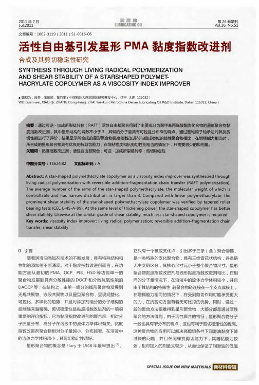
引发剂 AB 反应过程与 P MA均聚物的合成过程类似。 IN, L
得 到不 同分子量的 PL (MA・ —) b S。
1 R F 合成 甲基丙烯酸 月桂 酯 一 . 5 AT 苯乙烯嵌段共 聚物 为
臂 的星形聚合物 PL (MA— - )SDV b S一— B 与上述过程类似 , 加入不 同比例的 D VB, 反应一定时
l 实验部分 11 实验药 品 .
间得到 不同分子量的 PL ——) — V (MA bS一 D B星形聚合物 。 S 1 分析方法与仪器 . 6
Ni lt3 0 傅 里 叶 红 外 光 谱 仪 ( R), ic t k c e 6 o I V so e
G C Ma e2 0 P xV 0 1凝 胶 渗透 色谱 仪 , N H MR( 布鲁 克 4 0 ), 锥 剪 切 ( 0M 圆 企业 标 准 Q S H 0 82 0 或 /Y R 4 0 —0 3 C CL4 一 一9 E 一 5A 9 传动油剪切安定性测定法 ) 。
12 链转移剂 C B的合成 . D
聚合 , 溶液聚合 , 乳液聚合 , 微乳液聚合 , 离子液体和超
临界 C O 聚合 , 及高压聚合等 。R F 以 A T聚合与一 般的 自 由基聚 合相比 , 要是 引入 了链转移 剂 ( T 主 C A) , 链转移 剂的引入使 得自由基活性种首先与链转移剂进行可逆加成 ,
s
一
-
H
C l 7 ̄ O4/ 0 C
1 0 三颈瓶中加 入 3 0mL 0 0mL 0 四氢呋喃 ( 已除水 除 氧 ),0 的镁粉 ( 5.q 4 已用稀盐酸洗 去表面氧化层 , 干燥 ) . 氮气保护下 , 慢滴加入合 3 4g 缓 1 溴苯的 四氢呋喃溶液 ( 其 中合 T F 5 ), H I 0mL 控制温度约 5 C 0。。之后缓慢加入二 硫化碳 体系 呈深红色 , 加入 1mo/ 的盐酸绶 慢加入酸 l L 化 , 分液 , 收集有机相。加入 2 0mL 0 四氯化碳 , 0。下 7 C 加入 1 倍的 c 甲基苯 乙烯 , c 一 反应 2 之后旋干溶剂 , 4h 产 物经氧化铝柱纯化 , 呈紫红色液体 。 1 R F 合成聚 甲基丙烯酸月桂酯 P MA - AT 3 L 取一定量 L MA溶于 四氢 呋喃 , 加入一定 比例 C B, D 通氮 气 2 n 0mi 除氧 , 入一 定比例 的引发 剂 AB 加 IN的 四
固壁上液滴动力学的LBM建模与计算

f
k 0
(
eq
)
=αk nk
−
2 3
nk
ukeq
⋅ ukeq
(4)
( ) ( ) ( ) f= ik(eq)
1−αk 5
nk
+
1 3
nk
ei ⋅ ukeq
+
1 2
nk
ei ⋅ ukeq
2
−
1 6
nk
ukeq ukeq
=i
1, 2,3, 4
(5)
( ) ( ) ( ) f= ik(eq)
1−αk 20
Figure 1. Evolution of droplet spreading on solid wall 图 1. 液滴在壁面上的铺展演化过程
Figure 2. Evolution of droplet slipping on solid wall 图 2. 液滴在壁面上的滑移演化过程
DOI: 10.12677/app.2019.95032
271
应用物理
李阳贵,梁大成
式中 g 是单位质量的体积力。
2.3. 流体与固壁之间的相互作用
在流体/固体界面,固壁被视为具有恒定数密度的相。流体与壁面之间的作用力描述为
F3k ( x ) = −nk ( x ) ∑ gkwnw ( x′)( x′ − x )
(13)
x′
式中,nw 是墙的数量密度,在墙处为常数,在其他地方为零,gkw 是组分 k 与墙之间的相互作用强度。gkw 对非润湿流体为正,对润湿流体为负。通过调节,我们可以得到不同的润湿性。
272
应用物理
李阳贵,梁大成
4. 总结
本文基于 Shan-Chen 模型建立了固壁上液滴动力学模型,并成功地实现了该算法,模拟了重力作用 下液滴在固体表面上的铺展以及滑移动力学行为。
南开大学元素有机化学国家重点实验室所购买的FTMS为美国
傅立叶变换离子回旋共振质谱仪
南开大学元素有机化学国家重点实验室购买的FTMS为美国IonSpec生产的7.0T傅立叶变换离子回旋共振质谱仪。
该仪器具有高分辨率,高灵敏度,高精度和高稳定性等一系列特点。
对于单电荷化合物离子, 该仪器的质量分析范围可以从20到8000u。
可广泛用于有机化合物、元素有机化合物、生物大分子及合成聚合物的元素组成、分子量和结构等性质的测定和分析研究。
该仪器采用的离子源主要为电喷雾(ESI)和基质辅助激光解吸电离(MALDI)两种。
非常适合于检测热不稳定的化合物包括蛋白质、多肽等生物大分子。
可进行正、负离子的检测,以及单个离子的解离(SORI和ECD)的检测。
送样要求:
1.MALDI 和ESI源所需要的样品都需要溶解,因此送样时必需标明溶解该样品所需要的溶剂。
目前我们所备溶剂为去离子水,甲醇,二氯甲烷,乙腈,DMF,
丙酮。
2.已知的样品请提供准确的分子式和样品结构。
对于合成的新样品,请给出可能的分子式和结构。
未知样品请先做低分辨质谱,然后带着低分辨质谱数据做高分辨!
对于我们的FTMS装置,单电荷离子的理论测量范围为20-8000D。
由于ESI源
可使样品形成多电荷离子,因此用ESI源所检测的样品的质量范围与其所带电荷
的数量有关。
对于蛋白质,多肽等样品,测量范围可达到数万。
3.由于仪器构造的特殊性,金属有机的样品会对离子源系统造成极大的污染,因此该仪器杜绝测试任何金属有机物质。
送样时间:周一至周五上午8:30-11:30 下午2:30-5:00
联系人:李树奇
联系电话:23508129。
【国家自然科学基金】_超疏水表面_基金支持热词逐年推荐_【万方软件创新助手】_20140801

推荐指数 9 3 2 1 1 1 1 1 1 1 1 1 1 1 1 1 1 1 1 1 1 1 1 1 1 1 1 1 1 1 1 1 1 1 1 1 1 1 1 1 1 1 1 1 1 1
Hale Waihona Puke 2009年 序号 1 2 3 4 5 6 7 8 9 10 11 12 13 14 15 16 17 18 19 20 21 22 23 24 25 26 27 28 29 30 31 32 33 34 35 36 37 38 39 40 41 42 43 44 45 46 47 48 49 50 51 52
推荐指数 19 12 8 4 3 3 2 2 2 2 1 1 1 1 1 1 1 1 1 1 1 1 1 1 1 1 1 1 1 1 1 1 1 1 1 1 1 1 1 1 1 1 1 1 1 1 1 1 1 1 1 1
2011年 序号 1 2 3 4 5 6 7 8 9 10 11 12 13 14 15 16 17 18 19 20 21 22 23 24 25 26 27 28 29 30 31 32 33 34 35 36 37 38 39 40 41 42 43 44 45 46 47 48 49 50 51 52
53 54 55 56 57 58 59 60 61 62 63 64 65 66 67 68 69 70 71 72 73 74 75 76
微结构 微粒子图像测速 微气泡减阻 微-纳结构 圆管湍流 哲学意义 吸附 后接触线 十二硫醇铅 制备方法 几何设计 减阻机理 冷凝 偶氮苯 低表面能 仿生 二氧化钛 二氧化硅 中性氨基酸 两步法 三相接触线 一步法反应 zn片 zno纳米棒
纳米颗粒吸附法 纳米颗粒 粗糙度 粒子图像速度场测试技术 竹材 稳定性 碳酸钙/氧化硅复合粒子 硅 矿场试验 相分离 疏水表面 疏水性二氧化硅 界面 电化学阻抗谱 生物材料 生物性能 热阻 热模塑 激光加工 滴状冷凝 滑移速度 溶胶-凝胶法 溶胶-凝胶 水滴模板法 水性聚氨酯 氟化 模板 机械化学法 智能响应 无机非金属材料 改性 掺锑二氧化锡 接触角滞后 抗菌 抗结霜 抗结冰结霜 微观结构 微图案 影响因素 开关表面 层流 壁面滑移 喷砂 吸附 含氢硅油 化学气相沉积法 化学刻蚀 功能材料 功能化 几何设计 几何参数 冷凝 低粘着 传热系数
尖晶石LiMn_2O_4容量衰减的原因及性能改进

作者简介:万传云(1971-),女,河南人,上海应用技术学院化学工程系副教授,博士,研究方向:电化学及化学电源。
基金项目:上海市重点学科建设项目(P1501)尖晶石LiMn 2O 4容量衰减的原因及性能改进万传云(上海应用技术学院化学工程系,上海 200235)摘要:分析了尖晶石LiMn 2O 4容量衰减的原因:Jahn 2Teller 效应、Mn 的溶解、有机电解液的分解、Li 和Mn 的错位、自放电及不稳定的两相结构等。
从合成方法、掺杂及表面修饰等角度,介绍了抑制尖晶石LiMn 2O 4容量衰减和提高循环性能的方法。
关键词:锂离子电池; 尖晶石LiMn 2O 4; 容量衰减; 正极材料中图分类号:TM91219 文献标识码:A 文章编号:1001-1579(2007)06-0463-03Main factors inducing capacity fading of spinel LiMn 2O 4and the performance improvementWAN Chuan 2yun(Depart ment of Chemical Engineering ,S hanghai Institute of Technology ,S hanghai 200235,China )Abstract :The factors of spinel LiMn 2O 4capacity fading such as Jahn 2Teller effect ,dissolution of Mn ,decomposition of organicelectrolyte ,dislocation of Li and Mn ,self discharge and unstable structures of two phases were analyzed 1The methods to prevent the capacity fading and increase the cycle performance of spinel LiMn 2O 4were introduced from the points of view of synthesis method ,doping and surface modification 1K ey w ords :Li 2ion battery ; spinel LiMn 2O 4; capacity fading ; cathode material 尖晶石LiMn 2O 4用于锂离子电池,具有原材料丰富、价格低廉及对环境友好等优点,但在充放电过程中,特别是高温环境下存在容量衰减快和循环性能差的问题,使它在在锂离子电池中的实用化进程受到制约[1]。
碳纳米管海藻酸钠复合纳米纤维热稳定性研究

碳纳米管海藻酸钠复合纳米纤维热稳定性研究赵卫,夏延致,杨东江(青岛大学化学化工与环境学院,山东青岛2660711)摘要:近年来,静电纺丝技术制备的纳米纤维得到广泛应用,被认为是最简单有效的制备纳米级纤维的方法之一。
本文采用加入碳纳米管的海藻酸钠溶液高压静电纺丝,成功制备掺杂碳纳米管的海藻酸钠纳米纤维(SA-CNTs-NF)。
通过SEM、FT-IR、TG进行表征,检测表明,碳纳米管可以很好的分散在海藻酸钠纤维中,得到的SA-CNTs-NF平均直径约为196nm,并对SA-CNTs-NF进行了热重分析,发现加入碳纳米管的海藻酸钠纤维热稳定性有明显的提高。
关键词:静电纺丝;海藻酸钠;碳纳米管;热稳定性The Thermostability of Sodium Alginate Nanofibers with Carbon NanotubesZhao Wei,Xia Yanzhi,Yang Dongjiang(College of Chemistry&Chemical and Environmental Engineering,Qingdao University,Qingdao266071,China)Abstract:Recently,electrospinning has been widely used and regarded as one of the most efficient methods of producing nanofibers.In this report,we fabricated a new kind of nanofibers which combined sodium alginate with carbon nanotubes.The production was tested by SEM,FT-IR,TG,and the results turned out that the average diameter of the sodium alginate nanofibers with carbon nanotubes was196nm and the carbon nanotubes showed a good dispersion in the nanofibers.Through the TG analyzing, we found that the thermostability of sodium alginate nanofibers was improved by the addition of carbon nanotubes.Keywords:electrospinning;sodium alginate;carbon nanotubes;thermostability海藻酸钠(SA)是一种从褐藻的细胞壁中提取出来的天然多糖,由α-L-古罗糖醛酸(G)和β-D-甘露糖醛酸(M)组成,因其无毒、生物相容性好、容易凝胶化等优点而被广泛应用于生物、化学、医药、环保食品领域[1,2]。
10kW有机工质向心透平气动设计及优化研究

收稿日期:2016⁃06⁃22;最终稿修改日期:2017⁃11⁃29基金项目:国家国际科技合作专项项目(ISTCP)(2014DFA60990)。
作者简介:李 晓(1991⁃),女,工学硕士。
研究方向:有机工质汽轮机热力设计。
10kW 有机工质向心透平气动设计及优化研究李 晓1,2,张燕平2,朱志成2,黄树红1,2(1华中科技大学中欧清洁与可再生能源学院,武汉430074;2华中科技大学能源与动力工程学院,武汉430074)摘要:根据给定的工质R245fa 和透平输出功率10kW,利用MATLAB 软件编写有机工质向心透平气动设计程序,对设计输入参数进行敏感性分析,并利用遗传优化算法(Genetic Algorithm)对一维气动设计进行全局优化,得到约束条件下最高轮周效率为85.76%。
在ANSYS 平台上利用一维气动设计优化结果进行三维造型设计和计算流体力学(Computational fluid dynamics,CFD)数值模拟。
CFD 模拟结果显示,模拟的透平输出功率与一维设计结果误差为3%,透平效率误差为2.08%,说明一维气动设计准确性。
关键词:向心透平;气动设计;全局优化;数值模拟分类号:TK14 文献标识码:A 文章编号:1001⁃5884(2018)01⁃0011⁃04Aerodynamic Design and Optimization of 10kW ORC Radial⁃inflow TurbineLI Xiao 1,2,ZHANG Yan⁃ping 2,ZHU Zhi⁃cheng 2,HUANG Shu⁃hong 1,2(1China⁃EU Institute for Clean and Renewable Energy,Huazhong University of Science and Technology,430074Wuhan,China;2School of Energy and Power Engineering,Huazhong University of Science and Technology,430074Wuhan,China)Abstract :Computational program for aerodynamic design of ORC radial⁃inflow turbine was encoded by MATLAB,optimized for working fluid R245fa and a turbine output power of 10kW,to conduct sensitivity analysis on input parameters.The unidimensional aerodynamic design was optimized by using genetic algorithm,and a maximum wheel efficiency of 85.76%was achieved with constraints.The optimized result was used to run 3D profile design and Computational fluid dynamics (CFD)simulations by ANSYS.It is shown that the unidimensional aerodynamic design is accurate,with minor deviations of 3%on turbine output power and 2.08%on turbine efficiency.Key words :radial⁃inflow turbine ;aerodynamic design ;global optimization ;numerical simulation0 前 言近年来,由于资源短缺及环境污染等问题,对可再生能源的利用和能量回收的关注越来越多[1]。
响应面法优化分子蒸馏提纯神经酸工艺的研究

响应面法优化分子蒸馏提纯神经酸工艺的研究
呼晓姝;王建中
【期刊名称】《中国粮油学报》
【年(卷),期】2009(024)006
【摘要】应用刮膜式分子蒸馏装置对神经酸的提纯工艺进行了研究,分析了蒸馏温度、进料速率、到膜器转速三个操作因素对神经酸产品纯度及质量收率的影响.采用SAS软件程序对试验数据进行了二次响应面回归分析,对分子蒸馏工艺条件进行优化,得出分子蒸馏法提取神经酸的二次回归方程.刮膜式分子蒸馏技术提纯神经酸的优化条件为:系统压力0.1 Pa,蒸馏温度114.5℃,进料温度60 ℃,进料速率12 mL/h,刮膜器转速295 r/min.可以将原料中的神经酸由最初的6.07%提纯浓缩至39.02%,含量提高到原含量的近6.5倍.
【总页数】6页(P123-128)
【作者】呼晓姝;王建中
【作者单位】北京林业大学生物科学与技术学院,北京,100083;北京林业大学生物科学与技术学院,北京,100083
【正文语种】中文
【中图分类】TS224.6
【相关文献】
1.响应面法优化分子蒸馏提纯C22-环脂三酸二丁一甲酯工艺 [J], 吕宗莹;曾桂凤;周永生;夏明月;王建浩;王车礼
2.分子蒸馏纯化姜精油工艺的响应面法优化研究 [J], 彭晓敏
3.北化大分子蒸馏提纯二聚酸工艺 [J],
4.响应面法优化分子蒸馏脱除椪柑芳香油\r中柠檬烯工艺研究 [J], 王磊;林田;曹慧慧;项爱丽;齐彪;段晓然;张立田;汤思凝;杜瑞焕;阴明杰;张建雄
5.响应面法优化分子蒸馏提纯烟梗浸膏的工艺 [J], 冀唯妮;余其昌;黄菲;孔浩辉;周瑢;易聪华
因版权原因,仅展示原文概要,查看原文内容请购买。
高通量下超滤膜水厂应急除藻试验研究
高通量下超滤膜水厂应急除藻试验研究袁哲 陈卫 陶辉 陈亮(河海大学环境学院,南京 210098)摘 要为解决夏季高藻期超滤膜水厂在控制膜污染和提高产水量上的矛盾,保证水厂运行稳定和水质安全,进行以浸没式超滤膜为核心的组合工艺中试试验。
结果表明:采用高锰酸钾预氧化与混凝沉淀可以有效降低藻数目,超滤可以完全去除藻细胞。
适量的高锰酸钾投加量可使跨膜压差降低,但过高的投加量会使水中有机物成分发生变化,使膜污染加剧,最佳投加量为1.0mg/L。
增加膜表面气冲频率可以在不影响产水率的同时有效提高膜稳定运行的通量达20%。
组合应急工艺不会导致水厂运行成本大幅上升。
关键字超滤膜 除藻应急 高锰酸钾 跨膜压差 运行成本Study on emergency algae removal under high fluxin an ultrafiltration waterplantYuan Zhe ,Chen Wei, Tao Hui,,Chen Liang.(College of Environment Hohai University, Nanjing 210098, China) Abstract:To solve the ultrafiltration water plant’s contradiction of high flux and membrane fouling in summer when algae was high, and ensure the water plant security and stable, a pilot testing which using immersion membrane as the core of combined process was carried on. The results showed: pre-oxidation using potassium permanganat and coagulation could efficiently reduce the number of algae, ultrafiltration could totally remove algae cells. Appropriate amount of potassium permanganate dosage could reduce the transmembrane pressure, while exorbitant dosage made organic matter variety which increased membrane fouling, the best amount of potassium permanganate was 1.0mg/L. Increasing the frequency of membrane surface’s air impact was able to enhance the stable operating flux by 20% while didn’t affect the water producing rate. Combined emergency process would not lead to significant increase in water plant operation costs.Keywords:ultrafiltration membrane; algae emergency; potassium permanganate; transmembrane pressure; operation cost随着饮用水卫生标准的提高,常规水处理工艺已不能满足要求。
MOLECULAR DYNAMICS SIMULATION分子动力学模拟

38Leabharlann xiiixivCONTENTS
3
Hard Spheres 3.1 Kinematics of Hard-Sphere Collisions, 105 3.2 Collision Times, 108 3.3 Simulation Algorithm, 112 3.4 Initial Positions and Velocities, 115 3.5 Monitoring Equilibration, 117 3.6 Unpredictability, 123 3.7 Phase Diagram, 126 3.8 Assessing Reliability of Results, 130 3.9 Summary, 140 References, 141 Exercises, 142
148
5 Soft Spheres 5.1 5.2 5.3 5.4 5.5 5.6 Intermolecular Potential Models, 189 Initialization, 198 Equilibration, 204 Production, 210 Assessing Reliability of Results, 211 Summary, 216 References, 217 Exercises, 217
MOLECULAR DYNAMICS SIMULATION
Elementary Methods
J. M. HAILE Clemson University Clemson, South Carolina
Wiley Professional Paperback Edition Published 1997
188
6
Static Properties 6.1 6.2 6.3 6.4 6.5 Simple Thermodynamic Properties, 225 Thermodynamic Response Functions, 234 Entropic Properties, 243 Static Structure, 260 Summary, 265 References, 267 Exercises, 268
聚二甲基硅氧烷芯片自由酶反应器检测葡萄糖
聚二甲基硅氧烷芯片自由酶反应器检测葡萄糖仲海燕;周洁;余晓冬;陈洪渊【期刊名称】《分析化学》【年(卷),期】2010(38)6【摘要】应用电泳中介微分析(EMMA)技术,构建聚二甲基硅氧烷(PDMS)芯片自由酶反应器, 在线检测葡萄糖(Glu),在十字形的芯片通道上,采用自制的碳纤维微电极检测葡萄糖氧化酶(GOD)催化氧化Glu生成的H2O2,并对检测电位、GOD浓度、GOD进样时间、分离电压等参数进行了优化,测定了该自由酶反应器的线性范围和检出限,考察了其重现性及稳定性.结果表明,此自由酶反应器制作方便,操作简单,重现性好,Glu浓度在0.1~20 mmol/L之间有较好的线性关系(r=0.997),检出限为19.8 μmol/L(S/N=3).【总页数】4页(P767-770)【作者】仲海燕;周洁;余晓冬;陈洪渊【作者单位】南京大学化学化工学院,生命分析化学教育部重点实验室,南京,210093;南京大学化学化工学院,生命分析化学教育部重点实验室,南京,210093;南京大学化学化工学院,生命分析化学教育部重点实验室,南京,210093;南京大学化学化工学院,生命分析化学教育部重点实验室,南京,210093【正文语种】中文【相关文献】1.葡萄糖氧化酶修饰聚二甲基硅氧烷-纳米金电极的制备及其应用 [J], 王伟;毕连花;唐帆2.PDMS芯片自由酶反应器检测葡萄糖 [J], 仲海燕;周洁;余晓冬;陈洪渊3.PDMS芯片自由酶反应器检测葡萄糖 [J], 仲海燕;周洁;余晓冬;陈洪渊4.微型HPLC-固定化酶柱后反应器-电化学检测法测定血清和全血中的葡萄糖 [J], 邹公伟;文红梅5.用微芯片化学反应器实现酶催化化学发光测定葡萄糖的研究 [J], 徐溢因版权原因,仅展示原文概要,查看原文内容请购买。
文献翻译-PC ASA-共混物的低温韧性具有改进性
外文资料翻译PC/ASA-Blends with Improved Low Temperature ToughnessIntroductionFor many years, the automotive industry has been one of the application areas most open to innovations. Increasing demands in terms of environmental compatibility and thus lightweight construction for automobiles are the reasons for the ever-growing amount of plastics being used. In fact, plastics are even making inroads into the exterior car body parts that up to now has been the sole domain of the classic materials namely, steel and aluminium.During the last ten years, especially impact toughened PA/PPE- and PC/PBT-alloys were used as materials for fenders, bumpers or tailgates. These materials offer excellent impact strength, but suffer from their low dimensional stability.Blends based on amorphous components like PC and Styrenics offer a much higher dimensional stability as well as high toughness. They already have reached a sales volume of more than 300.000 t per year. In this paper we will discuss about the opportunities to use a new developed PC/ASA-blend as material for exterior car parts. Especially we will focus on the possibilities to improve the low temperature toughness of PC/ASA-blends.Experimental DetailsFor the preparation of the investigated materials the following raw materials were used:Polycarbonate (PC): Lexan 161 (General Electric Plastics)ASA- Rubber: PSAN-grafted Acrylate-Rubber with 65 wt.-% Rubber and a particle size of the grafted rubber particles (d50) of 510 nm.PSAN: Copolymer consisting of 80 wt.-% Styrene and 20 wt.-%AcrylonitrileSiloxane-Rubber: Metablen S 2001 (Elf-Atochem)HM-PMMA: PMMA with Mw=1800000 g/molThe blends were compounded using a twin screw extruder (ZSK 30, Werner & Pfleiderer).The samples for the mechanical testing were prepared by injection moulding according to ISO-standards. The materials temperature was 260°C, the mould temperature 80°C. The mechanical testing was performed according to ISO- and DIN-procedures:Charpy notched impact a k ISO 179 1eAPuncture Test Wt ISO 6603Melt volume index (260°C, 5kg) MVI ISO 1133Vicat B Vicat B DIN 53460The morphology of certain samples was investigated by transmission electron microscopy(TEM) using RuO4 as staining agent.DiscussionDimensional StabilityCompared to steel, thermoplastic materials suffer from a high coefficient of thermal expansion(CTE). Due to the fact, that the glass transition temperatures of some thermoplastic materials are in the area covered by the regular use- and paint conditions, the CTE of body panels made by thermoplastics show a significant temperature dependence. Although most of the materials have the same behaviour at room temperature , they behave quite different in the temperature range of the off-line painting procedure (80 –90°C). While the CTE of the completely amorphous material (PC/ASA-blend) is almost constant up to 100°C, the alloys containing semi-crystalline polymers show a significant increase of the CTE after passing the glasstransition temperature of their semi-crystalline component.Impact BehaviourAs previously mentioned, the impact at low temperatures (-30°C) is another point of interest for these applications. Due to the low glass transition temperature of the Polybutadiene-rubber, PC/ABS-blends offer a much higher toughness at low temperatures than PC/ASA-blends. As will be discussed later, Polybutadiene-rubbers on the other hand suffer from their limited thermal- and UV-resistance.In order to improve the low temperature impact toughness of PC/ASA-blends without loss of weather resistance, a part of the ASA-rubber was replaced by the commercially available Siloxane-rubber Metablen S 2001.With increasing content of Siloxane-rubber the notched impact at –30°C increases substantially whereas the melt flow index decreases. Due to the high rubber content of S 2001 the Vicat B-temperature decreases as well with increasing amount of S 2001 in the formulations .In order to achieve a substantial increase in low temperature toughness, 6 to 10 wt.-% of the Siloxane-modifier are necessary. This would lead to a significant increase in material costs. Therefore other alternatives to increase the toughness were evaluated.From the literature it was known, that PMMA can act as dispersant in PC/ABS-blends. Therefore the influence of high molecular PMMA (HM-PMMA) on the mechanical performance of PC/ASA-blends was studied .Already 1 wt.-% HM-PMMA gives a significant improvement of ak at –30°C. Larger amounts of HM-PMMA reduce the toughness at roomtemperature as well as the Vicat B temperature.The addition of HM-PMMA has a significant influence on the morphology of injection moulded samples. TEM-images of injection moulded samples without HM-PMMA have a anisotropic morphology with lamellar aggregates of ASA in the PC-matrix. The addition of HM-PMMA gives rise to a higher amount of spherical ASA-domains in the PC matrix, although also in this sample elongated ASA-domains are visible.Another approach to increase the toughness of PC/ASA-blends is to increase the amount of ASA-rubber in the system.This leads to a formulation with improved low temperature impact and good flow (Luran S KR 2868 C).Heat AgeingAs already mentioned Polybutadiene-based rubbers suffer from their limited thermal and UV-resistance.This can be demonstrated by annealing samples of PC/ASA and PC/ABS-blends at 90°C for several thousand hours. Even though PC/ABS-blends have a higher initial toughness in the puncture test as PC/ASA-blends, these materials lose their toughness due to the thermal degradation of the Polybutadiene-rubber. After 2500 hours PC/ABS-blends show a brittle fracture, with a low energy absorption in the puncture test, while PC/ASA-blends still behave ductile with a 90 %-retention of the initial energy absorption.UV-ResistanceAnother interesting feature of PC/ASA-blends is their excellent resistanceagainst UV-exposure. This property is another consequence of the Acrylate-rubber of the ASA component. As can be seen from figure 5, PC/ASA-blends with a white pigmentation and a clear coat painting show almost no colour shift (dE-value) during a period of 3000 h UV weathering whereas the colour of pigmented PBT/PC-blends changes significantly.This behaviour would allow the automotive industry to replace off line painted parts by pigmented and clear coat painted PC/ASA-parts in order to reduce system costs.Mechanical PropertiesA comparison of major mechanical properties between PC/ASA and PC/PBT or PA/PPE-alloys shows the superior performance of PC/ASA-blends . Compared to PA/PPE-alloys they offer a very low water absorption and a high E-modulus. Furthermore the room temperature impact toughness of PC/ASA is excellent and the impact strength at –30°C is in the same range compared to PA/PPE and PC/PBT-alloys.Compared to PC/PBT-blends, PC/ASA-blends show a higher HDT B-value, which is important during the paint procedure. The lower shrinkage of PC/ASA-blends compared to the blends with semi-crystalline polymers allows the preparation of large parts with better dimensional accuracy.ConclusionsPC/ASA-blends offer an interesting combination of mechanical properties and dimensional stability. Due to the stability of the Acrylate-rubber this material also features excellent heat and UV-resistance. The major drawback of this material, the limited low temperature impact toughness can be overcome by several measures. The new developed PC/ASA-grade Luran SKR 2868 C additionally offers improved low temperature impact. Therefore Luran S KR 2868 C has a high potential to replace PBT/PC and PA/PPE-alloys in exterior car part applications.PC / ASA-共混物的低温韧性具有改进性引言多年以来,汽车行业一直是最开放以及最有创新特性的应用领域之一。
- 1、下载文档前请自行甄别文档内容的完整性,平台不提供额外的编辑、内容补充、找答案等附加服务。
- 2、"仅部分预览"的文档,不可在线预览部分如存在完整性等问题,可反馈申请退款(可完整预览的文档不适用该条件!)。
- 3、如文档侵犯您的权益,请联系客服反馈,我们会尽快为您处理(人工客服工作时间:9:00-18:30)。
Dynamic Maintenance of Molecular Surfaces underConformational Changes∗Eran Eyal Dan Halperineyaleran@tau.ac.il danha@tau.ac.ilSchool of Computer ScienceTel Aviv UniversityAbstractWe present an efficient algorithm for maintaining the boundary and surface area of protein molecules as they undergo conformational changes.We also describe a robust im-plementation of the algorithm and report on experimental results with our implementation on proteins with hundreds of residues.Our work extends and combines two previous re-sults:(i)controlled perturbation for static molecular surfaces[18],and(ii)data structures for self-collision testing and energy maintenance of proteins that change conformation[25].As our method keeps an exact representation of the boundary surface and of the voids in the molecule,it can be useful in various applications such as Monte Carlo Simulation or Molecular Dynamics Simulation.In addition we propose and analyze an alternative method for efficiently recalculating the surface area under conformational(and hence topological) changes based on techniques for efficient dynamic maintenance of graph connectivity.1IntroductionA common approach to modeling the three-dimensional geometric structure of molecules is to represent each atom as a sphere offixed radius in afixed placement relative to the other atoms.The radius assigned to each atom depends on the type of the atom.There are various sets of recommended values for atom radii,depending on the specific application.The spheres are allowed to penetrate one another.This model,called the hard sphere model,has proven useful in many practical applications,in spite of its approximate nature.Molecular surfaces have many uses,such as drug design,studies of solvation and hydropho-bicity,the protein folding problem,and more.One type of molecular surface is simply the outer boundary of the union of the spheres in the hard sphere model.This type uses the van der Waals radii,and is often referred to as the van der Waals surface.There are two closely related types of surfaces:The solvent accessible surface introduced by Lee and Richards[23] is defined by the center of a solvent molecule,modeled as a hard probe sphere,when it rolls over the van der Waals surface.The smooth molecular(solvent excluded)surface introduced by Richards[28]is defined by the part of the surface of the solvent probe-sphere that faces the molecule.See also[8,9,11]and the survey by Mezey[26]for an extensive discussion on molecular surfaces.The study of the conformations adopted by proteins is an important topic in structural molecular biology.Some of the methodologies used for this study are Monte Carlo Simulation (MCS)[5,19]and Molecular Dynamics Simulation(MDS)[2,22].In MCS we randomly generate a series of trial steps in the conformation space of the studied molecule.Each such step consists of changing some degrees of freedom(DOFs)of the molecule,in general torsion (dihedral)angles around bonds.Classically,a trial step is accepted with a probability that depends on the difference in energy between the new and previous conformations,moving toward the lower energy conformation.In MDS we compute the forces on the atoms at each step,and use them to calculate the atom positions at the next step.Most MDS techniques update the Cartesian coordinates of the atoms at each step,but recently there has been growing interest in directly updating torsion angles[31].In the context of molecular simulations,the surface area of a molecule is required when calculating the energy of the molecule.To avoid using explicit solvent(actual water molecules) in such simulations,which considerably slows down the computations,implicit solvent models were introduced.In these models all solvent effects on a molecule can be included in an effective potential,which includes a term for non-polar contributations.This term is often modeled as a weighted sum of the solvent exposed or accessible surface area of each atom of the molecule (see[6]for a discussion and more references).Therefore fast methods to maintain the surface area of a molecule dynamically during conformation changes are desired.Several algorithms and their software implementation for calculation of the various surfaces mentioned above have been designed in the last two decades.The smooth molecular surface wasfirst computed by Connolly[8]and later in many other works[11,30,32,33].Halperin and Shelton[18]used controlled perturbation to calculate the van der Waals and the solvent accessible surfaces robustly.Limited dynamic maintenance of molecular surfaces was presented by Bajaj et al[3].They use non-uniform rational B-splines(NURBS)to represent molecular surfaces and dynamically maintain them as the radius of the solvent probe-atom changes continuously.Edelsbrunner et al[7]developed an algorithm for maintaining an approximating triangulation of a deforming surface in I R3,that adapts dynamically to changing shape,curvature,and topology of the sur-face.Sanner and Olson[29]presented surface reconstruction for moving molecular fragments. In their work they achieve a real-time reconstruction of the molecular surface when a small number of atoms move in each step(for example,a conformation change of a single side chainof the protein).The complexity of their algorithm is O (t log t ),where t is at least as high as the number of moving atoms.This means that a change in a single torsion angle located near the center of a protein chain,which moves the location of about half the atoms of the molecule,will take as much time asymptotically as it takes to recompute the entire surface.Lotan et al [25]introduced a fast implementation of MCS of proteins where a large number of atoms move in each step.They exploit the fact that proteins are long kinematic chains.In our work we maintain the boundary and surface area of proteins as they undergo con-formational changes.We exploit the fact that proteins are long kinematic chains (and not an arbitrary collection of spheres)and as the conformations change,we update the torsion angles of the protein backbone,instead of updating the Cartesian coordinates of the atoms,which allows us to modify the boundary of the molecule quickly even when a large number of atoms move,as is usually the case in conformation changes of proteins.The update time of the boundary depends on the number of intersecting pairs of atom spheres whose intersection circle changed,which is relatively small when just a few torsion angles are changed in each step of the simulation.Maintaining an exact representation of the boundary surface and of the voids of the molecule allows us to keep track of the surface area of the molecule and the contribution of each atom to the boundary and to the voids,which can be useful in various applications such as MCS and MDS.Our use of controlled perturbation ensures the robustness of our im-plementation even while using floating-point arithmetic.In our best experimental results we managed to update a molecular surface under conformational changes in 3%of the total time it would take to construct that surface from scratch.Our results indicate that our algorithm gives better gains for larger molecules.We also suggest an alternative method that could pos-sibly improve our implementation,based on efficient maintenance of graph connectivity,which yields an amortized update time of O (p log 2n )for each accepted conformational change where n is the total number of atoms in the molecule and p is the number of atom spheres whose intersection pattern with the other atom spheres was affected by a conformational change.The number p is typically much smaller than the number of moving atoms.2TerminologyAn arrangement of spheres —the subdivision of I R 3into vertices,arcs,faces and three-dimensional cells induced by a given finite collection of spheres.(Arrangements of curves and surfaces have been intensively studied and are widely used in Computational Geometry [1,14].)Given a set of spheres S ={s 1,s 2,...,s n },the spherical arrangement A (C )is the subdivi-sion of a sphere s i induced by the collection of circles C ={s i ∩s j |s j ∈S,j =i }which are formed by its intersections with the other spheres of S .The left-hand side image in Figure 1illustrates a spherical arrangement.A void —Let b i be the ball representing the atom whose boundary is the sphere s i .A void of the molecule is a bounded maximal connected component of I R 3\ n i =1b i .An exposed face of a spherical arrangement is a face that appears on the boundary of the union of the spheres (outer boundary orvoid).Figure 1:A spherical arrangement (left),its full trapezoidal decom-position (center)and its partial trapezoidal decomposition (right).Trapezoidal decomposition—Given a collection C of lit-tle circles on s i (namely intersec-tions of the sphere s i with otherspheres and hence not necessar-ily great circles),the trapezoidaldecomposition is a refinement ofthe spherical arrangement A (C )that makes each face of the ar-rangement homeomorphic to adisc with at most four edges on its boundary(see[14]for more details on trapezoidal de-compositions).In this context,wefix a pair of antipodal points as poles.We call the great circles through the poles polar circles and the arcs of polar circles polar arcs.Any point on a little circle that is tangent to a polar circle is called a polar tangency.For every polar tangency of every circle(except for circles that encompass a pole),we extend a polar arc in either direc-tion until it hits another little circle or reaches a pole.We do the same from every intersection point of a pair of little circles.This refinement is called the full trapezoidal decomposition. Occasionally it is sufficient to use the sparser partial trapezoidal decomposition,in which polar arcs are extended only from polar tangency points.Figure1illustrates both the full and partial trapezoidal decompositions of a spherical arrangement.ET-tree—a dynamic balanced binary tree over some Euler tour around a tree T.An Euler tour around a tree is a maximal closed walk over the graph obtained from the tree by replacing each edge by a directed edge in each direction.The walk uses each directed edge once,so if T has n vertices,the cyclic Euler tour has length2n−2.If we merge two trees or split a tree, the new Euler tours can be constructed by at most two splits and two concatenations of the original Euler tours,which take O(log n)time while maintaining the balance of the ET-tree. Each vertex of the tree may occur several times in the Euler tour,and one of these occurrences is chosen arbitrarily as a representative.Each ET-node represents the set of representative leaves below it,and may hold data that represent these leaves.See[20,21]for more details. 3Dynamic Maintenance Under Conformational ChangesWe compute an exact combinatorial and geometric representation of the boundary of a molecule (both the outer boundary and the voids),and the surface area of each connected component of the boundary.The contributions in terms of surface area of each atom to the outer boundary of the molecule and to the voids are also calculated.We initially compute this information when the molecule isfirst loaded.For that purpose we construct the spherical arrangement(Section 2)for each atom sphere and connect these spherical arrangements of intersecting atoms to form a subset of the3D arrangement of the spheres of the atoms,which is traversed in order tofind the two-dimensional faces of the arrangement that form the boundary of the molecule.First we outline the static construction of the surface(based on[18]),and then we explain the extensions for the dynamic maintenance of the surface under a conformation change. 3.1The Initial Construction of the SurfaceHalperin and Shelton presented a software package for computing the boundary surface of the union of spheres,the surface area of that boundary and the intersection pattern of any sphere with all the other spheres in a given set[18].They introduced a perturbation scheme,controlled perturbation,that overcomes degeneracies and precision problems in computing spherical ar-rangements while usingfloating-point arithmetic.We recently modified this package[15]to improve the running time,mainly by generalizing the implementation of the trapezoidal de-composition,which significantly reduced the perturbation time for large molecules.Given a collection S={s1,s2,...,s n}of n spheres,their arrangement A(S)is built in an incremental fashion(that is,adding one sphere at a time).The spherical arrangement of each sphere is connected to the spherical arrangements of the spheres that intersect it,to construct a subset of the three-dimensional arrangement of spheres that includes all the features of that arrangement except the3-dimensional cells.A subset of the2-dimensional faces of this structure forms the boundary surface of the molecule.We compute both the outer boundary and the boundary of each of the voids.In order to build the arrangements,it is required tofind all pairs of intersecting atoms.The implementation described in[18]uses a simple grid based solution[17].This data structure (called3D-hash)exploits the fact that Van der Waals potentials prevent atom centers fromcoming very close to one another.It can be computed in Θ(n )time,and determining which spheres intersect any given sphere of S takes O (1)time.Hence,finding all pairs of intersecting spheres takes Θ(n )time.After the arrangement of spheres is built,the boundary of the molecule is found by travers-ing the regions (two-dimensional faces)of the arrangement,starting from the bottommost region.During this traversal,the areas of the traversed regions are calculated and summed,to find the total surface area.This is repeated for each connected component of the boundary.3.2The ChainTreeWhen we allow the atoms of the molecule to move,it is practically expensive to update the 3D-hash and reconstruct the arrangements and the surface.Even though the grid algorithm is asymptotically optimal in the worst case,it requires reconstruction from scratch of the entire structure,which may be prohibitively slow for large molecules.In [25]Lotan et al introduced a novel data structure called the ChainTree (CT)aiming to speed up the energy computation during Monte Carlo Simulation of proteins.They take advantage of the fact that proteins are long kinematic chains (and not an arbitrary collection of spheres)and that few degrees of freedom (DOFs)are changed at each step of thesimulation.Figure 2:An illustration of a protein fragment with its backbone DOFs (taken from [24]).The C βatoms are part of the side chains,and the rest of the atoms belong to the backbone.The φtorsion angle is the angle between the plane of C NC αand the plane of NC αC .The ψtorsion angle is the angle between the plane of NC αC and the plane of C αC N .A protein is the concatenation of smallmolecules (the amino acids)forming a longbackbone chain with small side chains (calledresidues).Since bond lengths and angles be-tween any two successive bonds are almostconstant across all conformations at roomtemperature [13],it is common practice to assume that the only DOFs of a protein are its torsion angles.Each amino acid con-tributes two torsion DOFs to the backbone —the so-called φand ψangles.Thus,the backbone is commonly modeled as a long chain of links separated by torsion joints.A link,which designates a rigid part of a kine-matic chain [10],is a group of atoms with no DOFs between them.The side chains may also have degrees of freedom (between 0and 4),but in our current implementation we assume there are no DOFs in the side chains (see Section 6).Figure 2illustrates a fragment of a protein backbone with its DOFs.See Appendix A for more details regarding the CT.The performance of the CT is summarized in the following theorem,which is proved in [25].Theorem 1[25]Updating the CT after a k-DOFs change takes O (k log(n3)time.3.3The IntersectionsTreeIn our application we use the CT to detect self-collisions and to find the new pairs of intersecting atoms after performing DOF changes.When a DOF change is accepted (when it incurs no self-collisions),we have to modify some of the spherical arrangements and portions of the arrangement of spheres in order to compute the new boundary surface of the molecule and its area 1.We need to find all the intersecting pairs of atoms which changed due to the last DOF change.These pairs include deleted pairs that intersected before the change but no longer intersect,inserted pairs that did not intersect before the change but intersect afterthe change and updated pairs that intersected before and intersect after the change,but have moved relative to each other.Only pairs of atoms that belong to different leaves of the CT can be among those pairs we seek(because a pair of intersecting atoms from the same leaf can never move relative to one another).Tofind these pairs we introduce a data structure called the IntersectionsTree(IT),similar to the EnergyTree in[25]which was used to store partial energy sums in the Monte Carlo Simulation.In our case we store pairs of intersecting atoms. The definition of the IT,its update algorithm and the differnce between self-collisions and intersections are described in Appendix A.We summarize its worst-case performance in the following theorem.Theorem2The overall cost of updating the IT is2O(n42The O(n4the vertices of new and modified regions.For each deleted region,all the edges incident to its vertex in the graph are deleted.In order to maintain the connected components of the boundary of the molecule,we simply need to maintain the connected components of this graph as the molecule undergoes DOF changes.One connected component of the graph represents the outer boundary of the molecule and the rest of the components represent the voids.In[21]Holm et al present a poly-logarithmic deterministic fully-dynamic algorithm for graph connectivity.Their algorithm maintains a spanning forest of a graph,answers con-nectivity queries in O(log n)time in the worst case3and uses O(log2n)amortized time per insertion or deletion of an edge.Here n,the number of vertices of the graph,is assumed to be fixed as edges are added and removed.In our case the vertices are notfixed,since we create and delete regions during the DOF changes.However,the number of vertices throughout the simulation remains O(n)[17,25],and therefore the algorithm still works with the same amor-tized time bound.We next describe our extension of this algorithm to efficiently maintain the surface area of the boundary of the molecule without traversal of the entire boundary.The connectivity algorithm in[21]maintains a spanning forest F of the input graph G, and uses for this purpose a data structure called ET-tree(see Section2).The edges are splitof spanning forests is into max= log2n levels,and a hierarchy F=F0⊇F1⊇...⊇Fmaxmaintained,where F i is the subforest of F induced by the edges of level≥i.The amortization argument of the algorithm is based on increasing the levels of the edges(the level of each edge can be increased at most max times).In[21]each representative vertex of an ET-tree in the forest F i holds a key for each incident level i edge and each internal node of the ET-tree holds the number of representative leaves and one of the incident edges in its sub-tree.This information is maintained in O(log n)time per split or merge of the ET-trees.In a similar fashion,we add to each representative vertex the area of its respective region.Each internal node of the ET-tree will hold the sum of the areas of the representative leaves in its sub-tree.The root of each tree of F will hold the total surface area of that connected component.Maintaining the area information in the ET-trees takes O(log n)time per each split or merge of the ET-trees.Maintaining this information in the spanning forest F takes O(log2n)amortized time when an edge is inserted or deleted.Given any region of a given atom,we canfind the connected component it belongs to in O(log n) time byfinding the root of its tree in the spanning forest F.To summarize:Theorem4(i)The amortized cost of recalculating the surface area of the outer boundary and voids of the molecule is O(p log2n),where p is the number of atoms whose spherical arrangement is involved in a change.(ii)The cost of computing the contribution of an atom to the boundary and all the voids is O(log n).We have not yet implemented the graph connectivity algorithm suggested in this section. Its implementation could improve the running time of our application.4Controlled PerturbationAs mentioned earlier,the original static construction[18]uses controlled perturbation to over-come degeneracies and precision problems in the computation of the molecular surfaces with floating-point arithmetic.We extended the static scheme to work in the dynamic setting.We first describe the original scheme,and then the modifications required for the dynamic case.4.1Static Controlled PerturbationA possible way to compute robustly without resorting to exact computation during the eval-uation of predicates,is to(slightly)perturb the geometric objects such that correct resultsof the predicates can be certified even when usingfinite precision arithmetic.A degeneracy occurs when a predicate evaluates to zero.The goal of the perturbation scheme is to cause all predicates used during the algorithm to evaluate sufficiently far away from zero so that finite precision arithmetic could enable us to safely determine whether they are positive or negative.Hence,while certifying the correctness of the predicates,all degeneracies are elim-inated.Controlled perturbation has been successfully used with arrangements of polyhedral surfaces[27],with arrangements of circles[16],and recently with Delaunay triangulations[12]. The magnitude of the perturbation is utterly negligible in the context of molecular surfaces.In the case of arrangements of spheres,the general position(non-degeneracy)assumption means that there is no outer or inner tangency between two spheres,that no three spheres intersect in a single point,and that no four spheres intersect in a common point.The controlled perturbation scheme ensures that all the features of the spherical arrangements(vertices and arcs)are at least some givenεapart.As mentioned earlier,the arrangement A(S)is built incrementally.Each time we check if there is a potential degeneracy induced by the newly added sphere.If so,we perturb that sphere,so no degeneracies will occur.The main idea is to carefully relocate the sphere—move the sphere sufficiently to avoid all degeneracies,but not too much.We use a resolution parameterεthat depends on thefloating-point precision and the type of operations(but is assumed to be given here).For any given resolution valueε>0,a parameterδthat depends on εand m(the maximum number of spheres intersecting any single sphere,which is a constant for the hard sphere model[17])is determined.Each sphere center is perturbed by at mostδto resolve all the degeneracies.See Section5for the values ofδandεin our experiments.Another kind of degeneracies taken care of is degeneracies that result from the trapezoidal decomposition(Section2).Since in the trapezoidal decomposition we are free to choose a direction for the poles,the poles are chosen so that the angular separation of the additional arcs(of the trapezoidal decomposition)will be above a certain thresholdω.4.2Dynamic Controlled PerturbationWhen we extend the controlled perturbation scheme to the dynamic case,we have two goals in mind:(1)perturb as few atoms as possible,for efficiency reasons,and(2)avoid cascading errors as we perturb an atom several times or change a torsion angle several times.As described in Section3,after each set of simultaneous DOF changes we build a list of atom pairs(the MIL)whose intersection circles should be removed or added(or both)to their respective spherical arrangements.Removing the old intersection circles cannot induce new degeneracies,but adding the new circles can.We must therefore test,after each DOF change, for new degeneracies,and perturb the atoms if needed.As mentioned,we wish to test as few atoms as possible for degeneracies after each DOF change.As in the static perturbation,we want to keep all the features of the spherical arrangements at leastεapart,for the given resolution parameterε.For that goal it is not enough to know the new intersecting atom pairs,because a degeneracy occurs also when atoms almost intersect each other.Therefore we modify the MIL to include pairs of atoms which almost intersect each other.When the two checked atoms do not intersect,we check if their centers are less than r1+r2+ε+2δapart(where r1and r2are the radii of the atoms,εis the resolution parameter of the perturbation andδis the perturbation parameter).If so,we add them to the MIL(but not to the IT itself).By adding these pairs,we ensure that all pairs of atoms that intersect, or are less thanεapart,will be available to the dynamic perturbation routine.The added2δterm is required to ensure that a pair of atoms that were more thanεapart will remain more thanεapart after the(possible)perturbation of both of them.Now that we have a list of all the modified intersections and near intersections,we constructa list of all the atoms that might induce degeneracies.These are the atoms that belong to inserted and updated pairs and the atoms that belong to near intersecting pairs.For each of these atoms we perform the same tests that were performed in the static perturbation to assure that all the features areεapart.In the static perturbation we used the3D-hash tofind all the atoms that intersect or nearly intersect the tested atom.Now we do not have the3D-hash. However,when we built the spherical arrangement of each atom,we kept for each spherical arrangement a list of the atoms that intersect that atom.Taking this list and modifying it with the information stored in the MIL(removing atoms of deleted pairs and adding atoms of inserted and almost intersecting pairs),we can get the list of atoms intersecting or almost intersecting the tested atom after the current DOF change.Each atom tested for degeneracies is checked against this list.When wefind a degeneracy,we perturb the atom center within a sphere of radiusδaround the original center of the atom within its reference frame.This ensures that the center of the perturbed atom will be at mostδapart from its accurate place within the frame,which prevents cascading of errors caused when perturbing the same atom many times(in different steps). This,however,is not the case when we compute the global coordinates of the atom center.We have taken measures to avoid cascading of errors in transformations;we omit details for lack of space.The perturbation process is repeated until the atom no longer induces a degeneracy. For each perturbed atom we must re-compute its entire spherical arrangement including the circles of intersections of this atom with other atoms.Next we need to take care of the degeneracies that result from the trapezoidal decompo-sition.The atoms that need to be tested are atoms on which we add new polar arcs(due to changes in the relative position of some of the atoms that intersect with them).These are the same atoms whose centers were tested earlier for degeneracies.Again we have to re-compute the entire spherical arrangement of any atom whose poles direction is changed(as well as the intersection circles of this atom with other atoms).Theorem5The expected update time of the spherical arrangements including the perturbation time is O(p).5Experimental ResultsOur software is written in C++with an Open GL graphics interface.As mentioned in Sec-tion3.1,we modified the static construction of the surface as originally described in[18].See more details regarding this improvement in Appendix B.Our software reads PDBfiles[4].We identify the backbone and side-chain atoms,and divide them to maximal rigid groups(or links)without DOFs.We construct the backbone chain,and for each link of the chain compute its reference frame,and the transformation to the next link in the chain.For this purpose we use Atomgroup Local Frames as described in[34]:The origin of each frame(except for thefirst frame whose origin is the center of the backbone N atom)is the center of the backbone C or Cαatom that belongs to the relevant link.The z-axis of each frame(except for thefirst frame whose axes are the global axes)is the vector from the frame origin along the rotatable bond that connects this link to the previous link.The x-axis is perpendicular to the z-axis,and the y-axis completes the frame to form a right-hand system.Once we have a coordinate frame for each rigid link we can compute the transformation from each frame to its following frame.Next we use these transformations to compute the local frame coordinates of each atom center.From that point we use only local frame coordinates in our computations.When we need to work with coordinates that belong to different frames,we use the transformation between them to convert them to the same frame. We only have to compute the global coordinates of the atoms for displaying the molecule.The experiments described in this section were all executed on a1GHz Pentium III machine with2GB of ram.The perturbation parameters that were used areδ=10−7,ε=10−8and。
