DIN 5510 第6部分
din5510标准
D I N5510标准(总2页)--本页仅作为文档封面,使用时请直接删除即可----内页可以根据需求调整合适字体及大小--DIN 5510Preventive fire protection in railway vehicles,即铁路车辆防火保护措施。
共包括六个方面内容:一、防火等级、防火技术措施和证明。
二、火车材料和部件燃烧性能和并发现象,分类,要求和测试方法。
三、(暂缺)。
四、铁路轨道车辆防火保护措施;车辆构造;安全技术要求。
五、轨道车辆防火保护措施;电气设备;安全要求。
六、铁路轨道车辆防火保护措施;附带的措施;紧急制动设备、信息系统、火灾报警设备、灭火设备的功能;安全技术要求。
标准名称DIN 5510: Preventive fire protection in railway vehicles,即铁路车辆防火保护措施。
轨道车辆防火措施具体内容第一部分DIN 5510-1: Preventive fire protection in railway vehicles;Part1:levels of protection. fire preventive measures and certification.即防火等级、防火技术措施和证明。
第二部分DIN 5510-2 : Preventive fire protection in railway vehicles; Part 2: Fire behaviour and fire side effects of materials and parts, classification, requirement and test methods.即火车材料和部件燃烧性能和并发现象,分类,要求和测试方法。
具体如下:(1) 轨道车辆(火车)阻燃防火材料-小零部件DIN5510-2(手柄,广告牌等)-试验方法:DIN 53438 –可燃材料试验-等级判定:S1 (一般是最低要求)(2) 轨道车辆(火车)阻燃防火材料-成型构件DIN5510-2(密封条,墙面材料,天花板,涂料胶水等)> 试验方法:DIN 54837-轨道车辆用材料和构件试验-燃烧特性测定> 等级判定:-燃烧等级:S2-S5 (S2: 破坏长度≤30cm; S3: 破坏长度≤25cm, 后燃烧时间:100s; S4: 破坏长度≤20cm, 无后燃烧)-烟密度等级:SR1-SR2-熔滴性等级:ST1-ST2(3) 轨道车辆(火车)阻燃防火材料-地面材料DIN5510-2(包括涂料胶水等)-试验方法:ISO 9239-1 or DIN 4102-14 地板燃烧性能测定-等级判定:SF1-SF3(4) 轨道车辆(火车)阻燃防火材料-座椅DIN5510-2试验方法:DIN 5510-2, DIN EN 1021-1 and DIN EN 1021-2(5) 轨道车辆(火车)阻燃防火材料-电子电气设备DIN5510-2试验方法:EN 60695 (着火危险测试)(6) 轨道车辆(火车)阻燃防火材料-电线电缆DIN5510-2> 试验方法:- DIN EN 60332-1-2 单根线缆垂直燃烧试验- DIN EN 50266-2-4 整束线缆垂直燃烧试验- DIN EN 61034-2 烟密度燃烧试验第三部分(暂缺)第四部分DIN 5510-4:Preventive fire protection in railway vehicles; Part 4:vehicle design; safety requirements.即铁路轨道车辆防火保护措施;车辆构造;安全技术要求。
DIN_5510-22009德国轨道列车阻燃测试
DIN 5510-2:2009德国轨道列车阻燃测试随着中国轨道交通的迅猛发展,尤其是新一代列车技术(高速列车、磁悬浮,地铁等轨道交通工具)革新的成功应用,列车阻燃要求成为更加迫切的要求,关系国家生命财产的安危。
列车本身密闭、高速行驶的特性对阻燃技术提出更高的要求。
DIN 5510最初由德国提出对轨道客车的具体要求指标,具体包括以下几部分:第1部分:防火等级、防火技术措施和检测—第2部分:原材料和配件的燃烧特性与燃烧边界效应;分类,要求和检测程序—第4部分:设计车辆造型,安全技术要求—第5部分:电子运行设备;安全技术要求—第6部分:间接方法;紧急制动设备、信息系统、火警装置、消防设备的功能;安全技术要求。
目前,国内生产大多数轨道交通列车生产企业(包括北车、南车等)都要求最低符合DIN 5510,部分还要求达到英国BS 6853,法国NF F 16-101/102等同类技术指标。
随着DIN 5510标准的不断更新和完善,最新版本已经修订更新到DIN 5510:2009。
自DIN 5510:2007版本修订以来,烟雾毒性已经列入标准要求,在附录C中也给出具体测试要求及方法。
毒性要求的列入使DIN 5510与欧洲其他国家相关标准NF F 16-101/102、BS 6853更加趋于一致,更有可能欧盟将来出来统一标准。
烟雾毒性测试对材料的要求也更加高,很大一部分卤系阻燃剂可能将被挡在轨道列车的大门以外,更多环保阻燃剂比如膨胀型阻燃剂将会获得更广泛的应用。
DIN 5510-2:2009主要测试列车构件燃烧性能包括:火焰传播(S1~S5),熔滴物(ST1~ST2),烟雾密度(未达到SR1,SR1~SR2),烟雾毒性指数FED值。
另外,标准对于地板(SF1~SF3),座椅,电线电缆等特殊构件还有专门规定。
火焰传播分类S1检验方法:按照DIN 53438-1至DIN 53438-3;检验物数量:5个检验物;适用产品:根据标准5.3(b)的要求,包括:重量大于50g的小部件,例如:衣物挂钩,服务按钮,把手,吊环,座位牌,广告,门和阀片等等的止动缓冲器,必须至少达到易燃性等级S1的要求。
DIN5510-2轨道车辆材料测试
DIN5510-2标准概述DIN 5510-2: Preventive fire protection in railway vehicles; Part 2: Fire behaviour and fire side effects of materials and parts, classification, requirement and test methods.DIN 5510-2: 铁路车辆防火;第2部分:火车材料和部件燃烧性能和并发现象,分类,要求和测试方法。
为了对材料和构件的燃烧特性和燃烧并发现象(烟雾形成、液滴特性)进行分类,从而产生了易燃性、冒烟和液态等级并以允许曝光时间的形式确定毒性指数。
这些等级用来确定对制造车辆所用材料和构件的易燃性和燃烧并发现象的要求。
DIN5510-2主要测试可燃性分类: S1-S5;地面材料: SF1-SF3熔滴性能: ST1-ST2烟的发展分类: SR1-SR2毒性测试: EN ISO 5659-2 , FED(tzul)<1电线电缆多根垂直火焰燃烧: DIN 50266-2-4/ DIN50266-2-5电线电缆烟雾浓度: DIN EN 61034-2电线电缆单根垂直火焰燃烧: DIN EN 60332-1-2DIN5510-2相关标准DIN EN ISO 9239-1地面材料燃烧反应: 测试SF1-SF3的等级要求。
Reaction to fire tests for floorings - Part 1: Determination of the burning behaviour using a radiant heat source (EN ISO 9239-1:2010)DIN 54837: 采用气体火焰测试来决定S2-S5燃烧等级Testing of materials, small components and component sections for rail vehicles –Determination of burning behaviour using a gas burnerDIN 53438: Testing of combustible materials, response to ignition by a small flame,S1等级的燃烧测试。
DIN 5510-2-1996材料和结构部件的燃烧特性和燃烧附带影响
柴相比的煤气火焰(ISO 8191:1:1987 修订),德语版 EN 1021-2:
1993
DIN EN ISO 6941 纺织品 – 燃烧特性 – 测定垂直放置试件的火焰扩散特性(ISO
6491:1984 包括 1992 年第 1 次修订);德语版 EN ISO 6491:1995
DIN VDE 0304-3 电气绝缘材料的热性能 – 点火源影响时的易燃性; (VDE 0304
与标准有出入的点燃位置应进行约定。 对于厚度方向不对称的试样应对两侧进行点燃试验。如果 - 在表 5 到表 9 中给出说明;或者 - 可以证明,所要试验的一侧为危险的一侧
6
则点燃试验可以限制在一侧进行。
要求: - 损坏区域的长度:≤30cm。 - 再燃烧持续时间:允许在试验结束时将试样的再燃烧熄灭。 对结构部件、结构部件段、型材形状的结构部件,按照这一要求的精神或者如果可能
2
DIN 5510-1
铁路机车车辆预防性防火 - 防火等级、防火技术措施和证明
DIN 5510-4
铁路机车车辆预防性防火 - 车辆结构设计 - 安全技术要求
E DIN 50051-2 材料试验 – 材料的燃烧特性 – 带瞄准器的燃烧器
DIN 52273
矿物棉隔声、隔热材料试验 – 确定灼热损耗
DIN 53438-1
可燃性等级
临界辐射强度 kW/m2
光衰减的积分 % × min
SF1
≥2.5
无要求
SF2
≥2.5
≤2500
SF3Biblioteka ≥4.5≤7504.3 烟雾扩散等级和试验方法
按照要求,在进行燃烧试验期间,对于可燃性等级 S2 到 S5 要按标准 E DIN54 837 附
DIN V18599-6
Date: 2007 FebruaryDIN V18599-6 Energy efficiency of buildings — Calculation of the energy needs, delivered energy and primary energy for heating, cooling, ventilation, domestic hot water and lighting — Part 6: Delivered energy for ventilation systems and air heating systems for residential buildingsEnergetische Bewertung von Gebäuden — Berechnung des Nutz-, End- und Primärenergiebedarfs für Heizung, Kühlung, Lüftung, Trinkwarmwasser und Beleuchtung — Teil 6: Endenergiebedarf vonWohnungslüftungsanlagen und Luftheizungsanlagen für den WohnungsbauSupersedes DIN V 18599-6:2005-07DIN V 18599-6:2007-02Contents PageForeword (6)Introduction (8)1Scope (9)2Normative references (11)3Terms, definitions and units (13)3.1Terms and definitions (13)3.2Symbols, units and subscripts (18)4Relationship between the parts of the DIN V 18599 series of prestandards (21)4.1Input parameters from other parts of the DIN V 18599 series of prestandards (22)4.2Output parameters for other parts of the DIN V 18599 series of prestandards (22)4.3Calculation methods (23)4.3.1Ventilation heat sinks (23)4.3.2Heat losses, heat gains, auxiliary energy and generator heat output (25)4.3.3Heat generation with combined heating (27)5Energy need for heating (29)5.1Supply air temperature ϑV,mech (29)5.1.1Exhaust ventilation systems (29)5.1.1.1Exhaust ventilation systems without heat recovery (29)5.1.1.2Extract air/water heat pump (30)5.1.2Supply and exhaust ventilation systems (30)5.1.2.1Supply and exhaust ventilation systems without heat recovery (30)5.1.2.2Extract air/supply air heat exchangers (30)5.1.2.3Extract air/supply air heat pumps (33)5.1.2.4Extract air/water heat pumps (33)5.1.2.5Extract air/supply air/water heat pumps (34)5.1.3Air heating systems (34)5.2Mean ventilation system-driven air change rate n mech (34)5.2.1Exhaust ventilation systems (34)5.2.2Supply and exhaust ventilation systems (35)5.2.3Air heating systems (36)6Control and emission (37)6.1General (37)6.2Heat losses Q rv,ce (37)6.3Auxiliary energy Q rv,ce,aux (40)7Distribution (41)7.1General (41)7.2Heat losses Q rv,d and uncontrolled heat gains Q l,rv,d (41)7.3Auxiliary energy Q rv,d,aux (45)8Storage (46)8.1General (46)8.2Heat losses Q rv,s and uncontrolled heat gains Q I,rv,s (46)8.3Auxiliary energy Q rv,s,aux (48)9Generation (48)9.1General (48)9.2Heat losses Q rv,g and uncontrolled heat gains Q I,rv,g (49)9.3Auxiliary energy Q rv,g,aux (51)2DIN V 18599-6:2007-029.4Generator heat output Q rv,outg (57)9.4.1Exhaust ventilation systems (57)9.4.1.1Without heat recovery (57)9.4.1.2Extract air/water heat pump (57)9.4.2Supply and exhaust ventilation systems (62)9.4.2.1Supply and exhaust ventilation systems without heat recovery (62)9.4.2.2Extract air/supply air heat exchangers (63)9.4.2.3Extract air/supply air heat pumps (63)9.4.2.4Extract air/water heat pump (68)9.4.2.5Extract air/supply air/water heat pump (72)9.4.3Air heating systems (73)9.5Heat input Q rv,reg due to heat recovered from extract air (75)9.5.1Exhaust ventilation systems (75)9.5.1.1Exhaust ventilation systems without heat recovery (75)9.5.1.2Extract air/water heat pump (75)9.5.2Supply and exhaust ventilation systems (76)9.5.2.1Supply and exhaust ventilation systems without heat recovery (76)9.5.2.2Extract air/supply air heat exchangers (76)9.5.2.3Extract air/supply air heat pump (77)9.5.2.4Extract air/water heat pump (77)9.5.2.5Extract air/supply air/water heat pump (79)9.5.3Air heating systems (79)Annex A (normative) Ventilation systems (80)A.1Exhaust ventilation systems (80)A.1.1Exhaust ventilation systems without heat recovery (80)A.1.2Exhaust ventilation systems with extract air/water heat pump (82)A.2Supply and exhaust ventilation systems (83)A.2.1Supply and exhaust ventilation systems without heat recovery (83)A.2.2Supply and exhaust ventilation systems with extract air/supply air heat exchanger (84)A.2.3Supply and exhaust ventilation systems with extract air/supply air heat pump, with andwithout heat exchanger (86)A.2.4Supply and exhaust ventilation systems with extract air/water heat pump and with heatexchanger (87)A.2.5Supply and exhaust ventilation systems with extract air/supply air/water heat pump andheat exchanger (88)A.3Air heating systems (89)A.3.1With extract air/supply air heat pump, with and without heat exchanger, withoutrecirculation (89)A.3.2With heat exchanger, with recirculation (90)Bibliography (91)FiguresFigure 1 — Overview of the parts of DIN V 18599 (8)Figure 2 — Content and scope of DIN V 18599-6 (schematic diagram) (10)Figure 3 — System overview of ventilation systems for residential buildings in accordance with DIN 1946-6 (11)Figure 4 — Subscript system (21)3DIN V 18599-6:2007-02Figure A.1 — Exhaust ventilation system with single-room fans (80)Figure A.2 — Exhaust ventilation system with central fan (81)Figure A.3 — Exhaust ventilation system with heat pump (82)Figure A.4 — Supply and exhaust ventilation system without heat recovery (83)Figure A.5 — Supply and exhaust ventilation systems with extract air/supply air heat exchanger for a building (84)Figure A.6 — Supply and exhaust ventilation systems with extract air/supply air heat exchanger for a single room (85)Figure A.7 — Supply and exhaust ventilation systems with extract air/supply air heat pump, (with and without heat exchanger) (86)Figure A.8 — Supply and exhaust ventilation systems with extract air/water heat pump and heat exchanger (87)Figure A.9 — Supply and exhaust ventilation systems with extract air/supply air/water heat pump and heat exchanger (88)Figure A.10 — Air heating system with extract air/supply air heat pump, with and without heat exchanger, without recirculation (89)Figure A.11 — Air heating system with heat exchanger, with recirculation (90)TablesTable 1 — Symbols (used in all calculations in the DIN V 18599 series of prestandards) (18)Table 2 — Subscripts (used in all balance calculations in the DIN V 18599 series of prestandards) (19)Table 3 — Subscripts (specific to DIN V 18599-6) (20)Table 4 — General boundary conditions for determining the overall efficiency ηWÜT,mth (32)Table 5 — Default values for monthly supply air temperature for systems with extract air/supply air heat exchangers without preheating by ground/supply air heat exchangers, constructed after 1999 (33)Table 6 — General boundary conditions for determining the operating time t rv,mech (36)Table 7 — Factors f to be used when determining control and emission heat losses, Q rv,ce (38)Table 8 — Overall efficiencyηrv,ce for heat control and emission in the room (39)Table 9 — Rated power P c of the controller for heat control and emission in the room (40)Table 10 — Boundary conditions 1 for default values used to determine heat losses Q rv,d (44)Table 11 — Boundary conditions 2 for default values used to determine heat losses Q rv,d (45)Table 12 — General boundary conditions for determining the generation heat losses Q rv,g in relation to the type of ventilation system (50)Table 13 — Default values for determining the heat loss factor f ce,mth in relation to the ventilation system components and the location where they are installed (51)Table 14 — Degree-day values F Gt,Vorw of air preheating (in the respective month), in Kh, as a function of the activation temperature of frost-prevention operation (55)Table 15 — General boundary conditions for determining the auxiliary energy for heat generation Q rv,g in relation to the type of ventilation system (56)Table 16 — Default values for the volume flow-related fan power consumption P el,Vent of the fans (57)4DIN V 18599-6:2007-02Table 17 — Correction factors f T und fϑ for temperature deviations (60)Table 18 — Correction factor for air volume flow deviations (64)Table 19 — Maximum monthly operating times t on,h,i,max,mth of the extract air/supply air heat pumps in bins i (in the respective month), in h (65)Table 20 — Default values for the volume flow related power consumption and the performance coefficient of the heat pump (68)Table 21 — Default values for determining the monthly generator heat output of the extract air/supply air heat exchanger in combination with an extract air heat pump (68)5DIN V 18599-6:2007-02ForewordThis prestandard has been prepared by DIN Joint Committee NA 005-56-20 GA Energetische Bewertung von Gebäuden of the Normenausschuss Bau w esen (Building and Civil Engineering Standards Committee), which also lead-managed the work, and Normenausschuss Heiz- und Raumlufttechnik (Heating and Ventilation Standards Committee) with the co-operation of the Normenausschuss Lichttechnik (Lighting Technology Standards Committee).A prestandard is a standard which cannot be given full status, either because certain reservations still exist as to its content, or because the manner of its preparation deviates in some way from the normal procedure.No draft of the present prestandard has been published.Comments on experience with this prestandard should be sent:⎯preferably by e-mail containing a table of the data, to nabau@din.de. A template for this table is provided on the Internet under the URL http://www.din.de/stellungnahme;⎯or as hard-copy to Normenausschuss Bauwesen (NABau) im DIN Deutsches Institut für Normung e. V., 10772 Berlin, Germany (office address: Burggrafenstrasse 6, 10787 Berlin, Germany).The DIN V 18599 series of prestandards Energy efficiency of buildings — Calculation of the energy needs, delivered energy and primary energy for heating, cooling, ventilation, domestic hot water and lighting consists of the following parts:⎯Part 1: General balancing procedures, terms and definitions, zoning and evaluation of energy carriers⎯Part 2: Energy needs for heating and cooling of building zones⎯Part 3: Energy need for air conditioning⎯Part 4: Energy need and delivered energy for lighting⎯Part 5: Delivered energy for heating systems⎯Part 6: Delivered energy for ventilation systems and air heating systems for residential buildings⎯Part 7: Delivered energy for air handling and air conditioning systems for non-residential buildings⎯Part 8: Energy need and delivered energy for domestic hot water systems⎯Part 9: Delivered and primary energy for combined heat and power plants⎯Part 10: Boundary conditions of use, climatic dataThe DIN V 18599 series of prestandards provides a methodology for assessing the overall energy efficiency of buildings. The calculations enable all energy quantities required for the purpose of heating, domestic hot water heating, ventilation, air conditioning and lighting of buildings to be assessed.6DIN V 18599-6:2007-02 In the described procedures, the DIN V 18599 series of prestandards also takes into account the interactive effects of energy flows and points out the related consequences for planning work. In addition to the calculation procedures, the use- and operation-related boundary conditions for an unbiased assessment (i.e. independent of the behaviour of individual users and of the local climatic data) to determine the energy needs are specified.The DIN V 18599 series of prestandards is suitable for determining the long-term energy needs of buildings or parts of buildings as well as for assessing the possible use of regenerative sources of energy in buildings. The procedure is designed both for buildings yet to be constructed and for existing buildings, and for retrofit measures for existing buildings..AmendmentsThis prestandard differs from DIN V 18599-6:2005-07 in that it has been revised in form and content. Previous editionDIN V 18599-6: 2005-077DIN V 18599-6:2007-028IntroductionWhen an energy balance is calculated in accordance with the DIN V 18599 series of prestandards, an integrative approach is taken, i.e. the building, the use of the building and the building’s technical installations and equipment are assessed together, taking the interaction of these factors into consideration. In order to provide a clearer structure, the DIN V 18599 series of prestandards is divided into several parts, each havinga particular focus. Figure 1 provides an overview of the topics dealt with in the individual parts of the series.Figure 1 — Overview of the parts of DIN V 18599DIN V 18599-6:2007-021 ScopeThe DIN V 18599 series of prestandards provides a method of calculating the overall energy balance of buildings. The described algorithm is applicable to the calculation of energy balances for:⎯residential buildings and non-residential buildings;⎯planned or new building constructions and existing buildings.The procedure for calculating the balances is suitable for:⎯balancing the energy use of buildings with partially pre-determined boundary conditions;⎯balancing the energy use of buildings with freely selectable boundary conditions from the general engineering aspect, e.g. with the objective of achieving a good comparison between calculated and measured energy ratings.The balance calculations take into account the energy use for:⎯ heating,⎯ ventilation,⎯air conditioning (including cooling and humidification),⎯heating the domestic hot water supply, and⎯ lightingof buildings, including the additional electrical power input (auxiliary energy) which is directly related to the energy supply.This document describes a method of calculating the values for ventilation and air heating systems of residential buildings.This document describes the energy use of ventilation systems and air heating systems for residential buildings in conjunction with individual subsystems (control and emission, distribution, storage and generation). For this purpose, both the heat losses and the auxiliary energy of the individual subsystems are determined and, provided that these occur within the heated zone, are made available for the subsequent calculations described in DIN V 18599-1 and DIN V 18599-2.It is also possible to determine the use of subsystems for heat delivery to DIN V 18599-5 and DIN V 18599-8 and vice-versa. In such cases, the initial output data from DIN V 18599-1 and DIN V 18599-2, while the boundary conditions are obtained from DIN V 18599-10. It is also possible to calculate the energy balances of several building zones in which there are more than one units to be balanced.Figure 2 shows the scope of the present document as a diagram. For the reader’s orientation, all other parts of the DIN V 18599 series of prestandards contain an illustration similar to Figure 2 as shown here, and in which the respective energy components dealt with are shown in colour.9DIN V 18599-6:2007-0210 Figure 2 — Content and scope of DIN V 18599-6 (schematic diagram)The required energy use can be calculated using either the methods described in clauses 6 to 9 or by other methods (e.g. DIN V 4701-10, DIN V 4701-12 and PAS 1027), provided these alternative methods deliver equivalent results under comparable boundary conditions (see DIN V 18599-10). The assumptions and boundary conditions on which these calculations are based shall be recorded systematically and shall apply to the total annual heating need Q h,b.It is assumed that all system components have been designed according to the current rules of technology. The energy need values calculated using this procedure cannot be used to size individual components. Mechanical ventilation systems for residential buildings are classified into groups in accordance with DIN 1946-6 (see Figure 3). It is assumed that these systems are being operated as intended and in keeping with accepted best practice. Special guidance (e.g. in the planning and design of ventilation systems for residential buildings) is given in DIN 1946-6.Figure 3 — System overview of ventilation systems for residential buildingsin accordance with DIN 1946-6The combination of the ventilation system or air heating system of a residential building with other systems such as heating systems as described in DIN V 18599-5 or domestic hot water systems as described in DIN V 18599-8 is considered, and the respective balances can be calculated.If the building contains ventilation and air heating systems which are not described in this document, other physically sound algorithms may be used for the assessments, taking this document as a basis.This document does not include descriptions of systems for cooling and air conditioning of residential buildings nor of ventilation systems for non-residential buildings. These systems are described in DIN V 18599-7.2 Normative referencesThe following referenced documents are indispensable for the application of this document. For dated references, only the edition cited applies. For undated references, the latest edition of the referenced document (including any amendments) applies.DIN V 18599-1, Energy efficiency of buildings — Calculation of the energy needs, delivered energy and primary energy for heating, cooling, ventilation, domestic hot water and lighting — Part 1: General balancing procedures, terms and definitions, zoning and evaluation of energy carriersDIN V 18599-2, Energy efficiency of buildings — Calculation of the energy needs, delivered energy and primary energy use for heating, cooling, ventilation, domestic hot water and lighting — Part 2:Energy needs for heating and cooling of building zonesDIN V 18599-3, Energy efficiency of buildings — Calculation of the energy needs, delivered energy and primary energy for heating, cooling, ventilation, domestic hot water and lighting — Part 3: Energy need for air conditioningDIN V 18599-4, Energy efficiency of buildings — Calculation of the energy needs, delivered energy and primary energy for heating, cooling, ventilation, domestic hot water and lighting — Part 4: Energy need and delivered energy for lightingDIN V 18599-5, Energy efficiency of buildings — Calculation of the energy needs, delivered energy and primary energy for heating, cooling, ventilation, domestic hot water and lighting — Part 5: Delivered energy for heating systemsDIN V 18599-7, Energy efficiency of buildings — Calculation of the energy needs, delivered energy and primary energy for heating, cooling, ventilation, domestic hot water and lighting — Part 7: Delivered energy for air handling and air conditioning systems for non-residential buildingsDIN V 18599-8:2005-07, Energy efficiency of buildings — Calculation of the energy needs, delivered energy and primary energy for heating, cooling, ventilation, domestic hot water and lighting — Part 8: Energy need and delivered energy for domestic hot water systemsDIN V 18599-9, Energy efficiency of buildings — Calculation of the energy needs, delivered energy and primary energy for heating, cooling, ventilation, domestic hot water and lighting — Part 9: Delivered and primary energy for combined heat and power plantsDIN V 18599-10, Energy efficiency of buildings — Calculation of the energy needs, delivered energy and primary energy for heating, cooling, ventilation, domestic hot water and lighting — Part 10: Boundary conditions of use, climatic dataDIN 1946-6, Ventilation and air conditioning — Part 6: Ventilation for residential buildings — Requirements, performance, acceptance (VDI ventilation code of practice)DIN 4753-8, Water heaters and water heating installations for drinking water and for service water — Part 8: Thermal insulation for water heaters with nominal capacity up to 1000 l — Requirements and testingDIN EN 255-3, Air conditioners, liquid chilling packages and heat pumps with electrically driven compressors — Heating mode — Part 3: Testing and requirements for marking for sanitary hot water unitsDIN EN 308, Heat exchangers — Test procedures for establishing performance of air to air and flue gases heat recovery devicesDIN V 4701-10, Energy efficiency of heating and ventilation systems in buildings — Part 10: Heating, domestic hot water supply, ventilationDIN V 4701-12, Energetic evaluation of heating and ventilation systems in existing buildings — Part 12: Heat generation and domestic hot water generationDIN EN 13141-7, Ventilation for buildings — Performance testing of components/products for residential ventilation — Part 7: Performance testing of mechanical supply and exhaust ventilation units (including heat recovery) for mechanical ventilation systems intended for single family dwellingsDIN EN 13141-8, Ventilation for buildings — Performance testing of components/products for residential ventilation — Part 8: Performance testing of unducted mechanical supply and exhaust ventilation units (including heat recovery) for mechanical ventilation systems intended for a single roomDIN EN 14511-2, Air conditioners, liquid chilling packages and heat pumps with electrically driven compressors for space heating and cooling — Part 2: Test conditionsDIN EN 14511-3, Air conditioners, liquid chilling packages and heat pumps with electrically driven compressors for space heating and cooling — Part 3: Test methodsPAS 1027, Energy efficiency of heating and ventilation systems in existing buildingsISO 13600, Technical energy systems — Basic conceptsEnergieeinsparverordnung (EnEV) (German Energy Saving Ordinance) 2002/20043 Terms, definitions and units3.1 Terms and definitionsFor the purposes of this document, the following terms and definitions apply.3.1.1primary energycalculated quantity of energy, taking into account the energy required outside of the building by the preceding process chains for obtaining, converting and distributing the respective fuels used, in addition to the energy content of the required fuel and the auxiliary energy for the technical building installations3.1.2delivered energy (“energy use” in this document)calculated quantity of energy delivered to the technical building installations (heating system, ventilation and air conditioning system, domestic hot water system, lighting system) in order to ensure the specified room temperature, heat the domestic hot water and ensure the desired lighting quality throughout the yearNOTE This energy includes the auxiliary energy required to operate the technical building installations. The delivered energy is transferred at the “interface” constituted by the external building envelope and thus represents the amount of energy which the consumer requires in order to use the building for its intended purpose under standardized boundary conditions. Against this background, the energy use is expressed individually for each energy carrier.3.1.3energy needscollective term for the energy needs for heating, cooling, domestic hot water, lighting and humidification3.1.4energy need for heatingcalculated heat energy required in order to maintain the specified thermal room conditions within a building zone during the heating period3.1.5energy need for coolingcalculated cooling energy required in order to maintain the specified thermal room conditions within a building zone during periods in which the sources of heat generate more energy than is required3.1.6energy need for lightingcalculated energy required to illuminate a building zone with the quality of lighting specified in the usage profile3.1.7energy need for domestic hot watercalculated energy required to supply a building zone with the amount of domestic hot water at the required supply temperature specified in the usage profile3.1.8energy carriersubstance or phenomenon that can be used to produce mechanical work, radiation or heat or to operate chemical or physical processes3.1.9energy efficiency (energy performance)evaluation of the energy quality of buildings by comparing calculated energy ratings against standard energy ratings (i.e. with economically viable energy ratings from comparable new or renovated buildings) or bycomparing measured energy ratings against comparable values (i.e. with mean measured energy ratings from buildings with comparable types of usage)3.1.10conditioninggeneration of defined conditions in spaces due to heating, cooling, ventilation, humidification, lighting and domestic hot water supplyNOTE Conditioning aims to meet requirements relating to the room temperature, fresh air supply, light, humidity and/or domestic hot water.3.1.11conditioned spacespace and/or enclosure which is heated and/or cooled to a defined set-point temperature and/or humidified and/or illuminated and/or provided with ventilation and/or domestic hot waterNOTE Zones are conditioned spaces having at least one mode of conditioning. Spaces which have no form of conditioning are called “unconditioned spaces”.3.1.12zonebasic unit of space for calculating energy balancesNOTE 1 A zone is a cumulative term for a section of the floor area or certain part of a building having uniform boundary conditions of use and which does not exhibit any relevant differences in the mode of conditioning and other zone criteria. NOTE 2 DIN V 18599-10 contains a compilation of boundary conditions of use.3.1.13serviced areaarea comprising all those parts of a building which are served by the same technical building systemNOTE A serviced area (heating, domestic hot water, ventilation, cooling, lighting etc.) can cover several zones; a single zone may also include more than one serviced area.In keeping with the rules for calculating individual part-balances, it may be necessary to determine the energy use of an individual serviced area. The energy values determined for the serviced area are then distributed over the individual building zones as explained in DIN V 18599-1.3.1.14building servicestechnical building systems providing internal climate condition servicesNOTE 1 This document deals with heating, cooling, domestic hot water supply, ventilation, humidification and lighting.A building service may include more than one technical building system.NOTE 2 For example, the “domestic hot water supply” service includes both central and decentralized systems. Appropriate part-balances are assigned to each of the building services.3.1.15system boundaryouter delimitation of a zoneNOTE Rules for determining system boundaries are described in DIN V 18599-1.3.1.16envelope or thermal envelope areaouter delimitation of any zoneNOTE 1 The envelope or thermal envelope area is the boundary between conditioned spaces and the external air, the ground or unconditioned spaces. The cooled or heated spaces will lose heat or gain heat via this surface and, for this reason, it can be also called the “thermal envelope area”. Spaces which are not heated or cooled, but which have other forms of conditioning (e.g. lighting, ventilation) also have specific envelopes, but these do not contribute to heat transfer. For simplification, the designations “envelope” and “thermal envelope area” are used synonymously.NOTE 2 The envelope or thermal envelope area is formed by a material boundary, usually by the outer facade, internal surfaces, basement ceiling, ceiling of the top storey or by the roof. Rules for delimiting envelopes are described in DIN V 18599-1.3.1.17net floor area, reference areausable floor area within the conditioned volume of the buildingNOTE The net floor area (A NGF) is used as the reference area.3.1.18gross volume, external volume (V e)volume of a building or of a building zone as calculated on the basis of external dimensionsNOTE 1 This volume includes, at least, all the spaces in a building or zone which are directly or (since they are interconnected) indirectly conditioned as required for their function.NOTE 2 Rules for determining the gross volume are described in DIN V 18599-1.3.1.19net volume, air volume V(internal volume)volume which undergoes air interchange within a conditioned zone or within an entire buildingNOTE 1 The net volume is determined on the basis of the internal dimensions, i.e. the volume of the building structure itself is not included.NOTE 2 The net volume is calculated by multiplying the net floor area by the clear ceiling height. The clear ceiling height is the difference in height between the upper face of the floor and the lower face of the storey floor above or suspended ceiling. As an estimate, (if no internal measurements are taken, for instance) the net volume is calculated using the equation V = 0,8 ×V e, with V e being the gross volume (external volume).3.1.20reference internal temperaturemean internal temperature of a building or a building zone on which the calculations of the energy needs for heating and cooling are based. Also the mean temperature based on heating patterns with limited heating in certain sections or at certain times and, where the energy need for cooling is to be calculated, taking into account the permitted temperature variationsNOTE Different temperature values are usually assumed for heating and for cooling, respectively.3.1.21external temperaturetemperature of the external air, which is determined by meteorological measurement and evaluation and is taken as a basis for the calculations3.1.22heat sinkquantity of heat drawn out of the building zoneNOTE This does not include heat removed by means of the cooling system.。
德国标准DIN5510
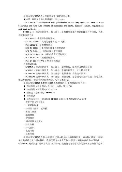
德国标准DIN5510-2火车材料防火/阻燃测试标准:◆德国-铁路交通防火测试标准DIN 5510-2• DIN 5510-2 : Preventive fire protection in railway vehicles; Part 2: Fire behaviour and fire side effects of materials and parts, classification, requirement and test methods.DIN 5510-2: 铁路车辆防火;第2部分:火车材料和部件燃烧性能和并发现象,分类,要求和测试方法• DIN 54837: 小型部件燃烧测试• EN ISO 9239-1: 火焰的延伸测试–地板• DIN 53438-2: 易燃材料测试• DIN EN 60332-1-2:单根电缆垂直燃烧测试• DIN EN 61034-1: 电线电缆烟密度测试• DIN EN 50266-2-4: 多根电缆垂直燃烧测试• DIN EN 1021-1: 座椅燃烧测试• DIN EN ISO 5659-2 : 烟雾毒性测试其他测试标准:• DIN5510-1铁路车辆防火;第1部分:阻燃等级,阻燃技术措施和说明;• DIN5510-4铁路车辆防火;第4部分:车辆结构设计;安全技术要求;• DIN5510-5铁路车辆防火;第5部分:电器设备;安全技术要求;• DIN5510-5铁路车辆防火;第6部分:附加措施,紧急制动装置的性能,信号系统,燃烧警报系统。
燃烧控制系统的性能;安全技术要求。
德国标准DIN5510-2/DIN 54837火车材料防火/阻燃测试内容包含:◆燃烧性能(等级判定:S1-S5;地板:SF1-SF3)◆熔滴性能(等级判定:ST1-ST2)◆烟密度(等级判定:SR1-SR2)◆毒性测试◆火车防火材料-德国标准DIN5510-2防火/阻燃测试的产品范围:• 橡胶产品(密封条)• 三聚氰胺泡沫• 纺织品(窗帘,遮阳板)• 海绵(座垫)• 地面材料•塑料制品•铝蜂窝板(地板)•防火涂料• 防火胶水• 电线电缆• 火车座椅德国标准DIN5510-2防火/阻燃测试将由防火材料的具体用途(如地板,墙面,座椅)决定测试的方法与判定标准。
欧洲轨道车辆防火标准对比及借鉴

欧洲轨道车辆防火标准对比及借鉴摘要:对欧洲主要的轨道车辆防火标准进行了介绍和总结,对比了这些标准在测试方法和评价指标等方面的差异,并说明了对我国防火标准的借鉴及参考意义。
关键词:轨道车辆;防火标准轨道车辆防火安全是车辆设计中的首要问题,是保证列车安全运行的基础和必要条件。
目前,在轨道车辆防火标准研究方面比较成熟的德国,英国,法国等国家,根据其考虑问题的侧重点不同,对材料防火制定了不同的标准,本文将介绍和比较这些标准,并说明对我国防火标准的借鉴及参考意义。
1.德国标准德国的铁路防火标准DIN 5510是系列标准,其中DIN 5510-2《材料和构件的燃烧特性和燃烧并发现象:分类、要求和测试方法》是轨道车辆材料的防火要求。
在DIN 5510-1标准中,根据车辆运行线路设施条件以及逃生的可能性和失火后的风险,把车辆分为4个阻燃保护等级(见表1)。
表1 DIN 5510中的客车车辆阻燃保护等级DIN 5510-2中根据DIN 5510-1中规定的客车车辆阻燃保护等级以及零部件的安装位置等特点,明确了材料的防火性能要求。
防火性能包括可燃性、烟雾性、滴落性及烟气毒性等。
主要指标有S、SF、ST、FED等。
1)易燃等级由低到高分为S1,S2-S5,主要考核材料的烧毁长度和续燃时间;SF1-SF3适用于地板面层易燃等级,主要考核材料燃烧时的消光情况;2)烟雾生成等级由低到高分为SR1和SR2;3)滴落物生成等级由低到高分为ST1和ST2,主要考核材料燃烧的滴落现象;4)烟气毒性,FED-有效计量百分数,主要考核烟气毒性情况。
1.英国标准英国铁路防火标准BS 6853《铁路客车设计和建造火灾预防实施规范》,加强了铁路车辆设计者和制造商的责任,规定了设计中的注意事项,例如:乘客头上的行李架应设计为从下面可以看到摆放的物品。
强调了列车建造材料的特性及防火性能,对材料的选择制定了目标,例如:控制燃烧源的能量、持续时间及着火频率;控制材料对多种燃烧源的反应等。
DIN 5510-1-1988预防性防火,防火等级,防火技术措施和证明
合格证明是以不断地监控生产工艺为补充的。这种生产工艺监控的结果是要由具体材 料供应商或车辆供应商提供证明文件的。
对其它车辆未按防火等级分级。
防火等 级 1
2
3
表 1.客车防火等级
标段使用客车而存在火险,则应在此
让客车进入另一车道。
如果权威性地确定因在地下线路区段使用客车而存在火险,并且各紧急
停车场之间距离在 2000m 以上,则应在此让客车进入另一车道。
如果权威性地确定因在地下线路区段使用客车而存在火险,并且地下线
定义:在由运营条件和设计结构状况决定的停留时间内能够拯救火灾影响范围内的旅 客。火灾影响范围系指在这个范围内因车辆起火造成的各种影响会危及到人员健康的那种
4
DIN 5510-1988
空间范围。 第 31 委员会认为有必要通过适当的研究计划实验性地研究这些措施的效果。因为需
要费用开支和付出劳动这只能分若干个步骤才有可能实现,所以在第 1 个工作阶段首先要 研究用于子保护目标 1 的措施。在这些研究的第 1 个工作阶段结束后将要发表的该标准各 部分的第 1 个版本,只应在迄今已有的可靠的经验和认识范围内完全满足子保护目标 1 和 其它的子保护目标。但是,第 31 分委员会认为,特别是对满足子保护目标 3 而言,如果 不进行进一部的研究,这些认识和经验还是不够用的。在后续版本中更新标准时要考虑到 进一部工作阶段中所获得的认识。
本标准由德国标准研究所铁路机车车辆专业标准委员会编写。 本标准包括安全技术规定。 生效开始日期 本标准自 1988 年 10 月 1 日起生效。
DIN_50960-02-2006_电镀涂层.第2部分图纸说明

DIN_50960-02-2006_电镀涂层.第2部分图纸说明N02 206Textile Systems Electroplated Coatings 002-en Technical Design Manual Indications on technical drawings DIN 50960-2 Page 1/1 Release: S. Liefert DTTNS 2003-11-25 Change: S. Liefert DTTNS 2006-02-21The following Standard is used at Rieter:DIN 50960-2: January 2006, pages 1 - 16 Electroplated CoatingsPart 2: Indications on technical drawingsJanuar 2006DEUTSCHE NORM Normenausschuss Technische Grundlagen (NATG) im DINNormenausschuss Materialprüfung (NMP) im DINPreisgruppe 11DIN Deutsches Institut für Normung e.V. ? Jede Art der Vervielf?ltigung, auch auszugsweise, nur mit Genehmigung des DIN Deutsches Institut für Normung e. V., Berlin, gestattet.ICS 25.220.40 Gg 9659618www.din.de X DIN 50960-2Galvanische überzüge –Teil 2: ZeichnungsangabenElectroplated coatings –Part 2: Indications on technical drawingsDép?ts électrolytiques –Partie 2: Indications dans les dessins techniquesAlleinverkauf der Normen durch Beuth Verlag GmbH, 10772Berlin Ersatz fürDIN 50960-2:1998-12www.beuth.deGesamtumfang 16 SeitenDIN 50960-2:2006-01VorwortDiese Norm wurde vom Normenausschuss Technische Grundlagen (NATG) —Fachbereich F …T echnische Pro duktdokumentation“, Arbeitsausschuss NATG-F.5 …Technisches Zeichnen“, mit Beteiligung des Arbeits-ausschusses NMP 176 …Galvanische überzüge“ erarbeitet.Die Norm regelt die Eintragung der Zeichnungsangaben in Abstimmung mit der in DIN EN 1403 festgelegten und in DIN 50960-1 erg?nzten Methodik der Bezeichnung.DIN 50960 besteht aus:DIN 50960-1: Galvanische überzüge — Teil 1: Bezeichnung in technischen DokumentenDIN 50960-2: Galvanische überzüge —Teil 2: ZeichnungsangabennderungenGegenüber DIN 50960-2:1998-12 wurden folgende ?nderungen vorgenommen:a) die graphischen Symbole der Oberfl?chenbeschaffenheit in den Bezeichnungen von überzügen und dieAngaben der Oberfl?chenbeschaffenheit in technischen Zeichnungen wurden an DIN EN ISO 1302 angepasst;b) in den Bildern 1, 3, 4, 5, 7, 8, 11, A.1, A.2, A.4 und A.5 wurden die Bezeichnungen von überzügenpr?zisiert;c) in den Bildern 6, 9, 10, A.5 und B.1 wurden die Angabenvon überzügen an DIN EN ISO 6158 angepasst;d) im Anhang C wurden Beispiele gestrichen;e) die im Text zitierten Normen wurden aktualisiert;f) die Norm wurde redaktionell überarbeitet.Frühere AusgabenDIN 50960: 1955-01, 1963-06DIN 50960-2: 1986-02, 1998-122DIN 50960-2:2006-011 AnwendungsbereichDiese Norm gilt für Angaben von galvanischenüberzügen in technischen Zeichnungen.ANMERKUNG Gegenst?nde mit Gewinde siehe auch DIN EN ISO 4042.2 Normative VerweisungenDie folgenden zitierten Dokumente sind für die Anwendung dieses Dokuments erforderlich. Bei datierten Verweisungen gilt nur die in Bezug genommene Ausgabe. Bei undatierten Verweisungen gilt die letzte Ausgabe des in Bezug genommenen Dokuments (einschlie?lich aller ?nderungen).DIN 30-10, Technische Zeichnungen —Zeichnungsvereinfachung — Teil 10: Vereinfachte Angaben und Sammelangabe n, AusführungDIN 406-10, Technische Zeichnungen — Ma?eintragung —Teil 10: Begriffe, allgemeine GrundlagenDIN 406-11, Technische Zeichnungen — Ma?eintragung —Teil 11: Grundlagen der AnwendungDIN 6773, W?rmebehandlung von Eisenwerkstoffen —Darstellung und Angaben w?rmebehandelter Teile in ZeichnungenDIN 50902, Schichten für den Korrosionsschutz von Metallen — Begriffe, Verfahren und Oberfl?chen-vorbereitung DIN 50960-1, Galvanische überzüge — Teil 1: Bezeichnung in technischen DokumentenDIN EN 1403, Korrosionsschutz von Metallen — Galvanische überzüge —Verfahren für die Spezifizierung allgemeiner AnforderungenDIN EN 12329, Korrosionsschutz von Metallen —Galvanische Zinküberzüge auf Eisenwerkstoffen mit zus?tzlicher BehandlungDIN EN 12540, Korrosionsschutz von Metallen —Galvanische Nickel-überzüge und Nickel-Chrom-überzüge, Kupfer-Nickel-überzüge und Kupfer-Nickel-Chrom-überzüge DIN EN ISO 1302, Technische Produktdokumentation (GPS) —Angabe der Oberfl?chenbeschaffenheit in der technischen ProduktdokumentationDIN EN ISO 2064, Metallische und andere anorganische Schichten —Definitionen und Festlegungen, die die Messung der Schichtdicke betreffenDIN EN ISO 6158, Metallische überzüge —Galvanische Chromüberzüge für technische ZweckeDIN ISO 128-24, Technische Zeichnungen —Allgemeine Grundlagen der Darstellung — Teil 24: Linien in Zeichnungen der mechanischen Technik3 BegriffeFür die Anwendung dieses Dokuments gelten die Begriffe nach DIN 50902, DIN EN ISO 2064 und DIN EN ISO 6158.3DIN 50960-2:2006-0144 Zeichnungsangaben4.1 AllgemeinesDie Angabe der Bezeichnung von überzügen erfolgt an einem graphischen Symbol der Oberfl?chen-beschaffenheit nach DIN EN ISO 1302 (siehe Bild 1).Bild 1 —Beispiel für Angabe von überzügen4.2 BezeichnungDie Bezeichnung galvanischer überzüge ist in DIN EN 1403 und in den Normen für die jeweiligen galvanischen überzüge oder überzugskombinationen festgelegt.Für Bezeichnungen galvanischer überzüge, die durch eigenst?ndige Normen nicht erfasst sind, gilt DIN 50960-1.4.3 Kennzeichnung begrenzter BereicheBereiche werden durch in Tabelle 1 angegebene Linienarten nach DIN ISO 128-24 gekennzeichnet.Tabelle 1 —Linienarten und deren Anwendung Linienart Bedeutung04.2Bereiche, die entsprechend der Bezeichnung einen überzug erhalten müssen; wesentliche Fl?chen 02.2 Bereiche, die einen überzug haben dürfen, der aber nichterforderlich ist05.1Bereiche, die innerhalb von 04.2 und 02.2 keinen überzug habendürfen Die Bedeutung der Linienarten 02.2 und 05.1 darf a uf der Zeichnung erkl?rt sein. Nicht gekennzeichnete Bereiche dürfen keinen überzug haben.Die Linienart 05.1 (siehe Bild 11) ist nur anzuwenden, wenn Geometrieelemente (z. B. Bohrungen) und Fl?chen, die innerhalb der Bereiche 04.2 und 02.2 liegen, keinen überzug erhalten dürfen.An symmetrischen Teilen und Geometrieelementen genügt eine halbseitige Kennzeichnung (siehe Bilder 5 und 7).DIN 50960-2:2006-0154.4 Sammelangaben4.4.1 AllgemeinesKann die Angabe für den überzug nicht in derSammelangabe für die Oberfl?chenbeschaffenheit mit angegeben werden, so ist eine eigene Sammelangabe für den überzug zu machen. Getrennte Sammel-angaben für überzüge und die Oberfl?chenbeschaffenheit sind in der Zeichnung untereinander anzuordnen (siehe Anhang A).Sammelangaben sind nach DIN 30-10 und DIN EN ISO 1302 auszuführen.4.4.2 überzug allseitig, mit gleichen AnforderungenEin einheitlicher, allseitiger überzug wird nach Bild 1, z. B. in der N?he des Schriftfeldes bzw. im Schriftfeldangegeben (siehe Bild 2). Alle Fl?chen des Teiles gelten dann als wesentliche Fl?chen (Funktionsfl?chen).Bild 2 —Beispiel für Angabe von allseitigen überzügen4.4.3 überzug allseitig, mit unterschiedlichen AnforderungenWenn die Mehrzahl der Fl?chen eines Gegenstandes eine einheitl iche Hauptanforderung erh?lt und für die restlichen Fl?chen (wesentliche Fl?chen) spezielle Anforderungen gestellt werden (siehe Bild 3), so wirddie Hauptanforderung für die Mehrzahl der Fl?chen über dem bzw. im Schriftfeld als Sammelangabe miteinem graphischen Symbol nach DIN EN ISO 1302 angegeben,die spezielle Anforderung in der Darstellung an einer breiten Strich-Punktlinie (Linienart 04.2 nach 4.3)eingetragen und in der Sammelangabe nach der Hauptanforderung in Klammern vereinfacht angegeben (Grundsymbol nach DIN EN ISO 1302 bedeutet, dass in der Darstellung des Gegenstandes entsprechende spezielle Anforderungen eingetragen sind).Für unterschiedliche überzüge und Zwischenbearbeitungenist ein Beschichtungsbild auf der Zeichnung odereine spezielle Beschichtungszeichnung anzufertigen (siehe Bild B.1).Bild 3 —Beispiel für Angabe einer speziellen AnforderungDIN 50960-2:2006-0164.5 Einzelangaben4.5.1 Bereiche mit geforderter BeschichtungWenn an einem Teil nur einzelne Bereiche einen überzug erhalten sollten, werden diese Bereiche durch eine Strich-Punktlinie breit (Linienart 04.2 nach DIN ISO 128-24) gekennzeichnet. Alle in dem so gekenn-zeichneten Bereich liegenden Bohrungen, Gewindel?cher, Aussparungen usw. sind ebenfalls wesentliche Fl?chen, au?er, sie werden mit der Linienart 05.1 gekennzeichnet.Auf den nicht gekennzeichneten Bereichen darf kein überzug vorhanden sein. Die Angabe der überzugsart erfolgt an der Strich-Punktlinie (siehe Bild 4) oder als vereinfachte Angabe mit Erkl?rung der Strich-Punktlinie und des graphischen Symbols nach DIN EN ISO 1302 (siehe Bilder 5 und 6).Bild 4 —Beispiel für Angabe von Bereichen mit geforderter BeschichtungBild 5 —Beispiel für vereinfachte Angabe der überzugsartDIN 50960-2:2006-017Bild 6 —Beispiel für vereinfachte Angabe der überzugsart4.5.2 Bereiche mit zugelassener BeschichtungBereiche au?erhalb der wesentlichen Fl?chen, die einen überzug erhalten dürfen, sind durch eine Strichlinie breit (Linienart 02.2) zu kennzeichnen (siehe Bild 7).Bild 7 —Beispiele für Angabe von Bereichen mit zugelassener BeschichtungANMERKUNG Unterschiedliche aneinander anschlie?ende Bereichskennzeichnungen k?nnen durch eine schmale Trennungslinie (Linienart 01.1 nach DIN ISO 128-24) voneinander abgegrenzt werden (siehe Bild 7). Die Bedeutung der Linie ist zuerl?utern, wenn dies zur Klarheit der Zeichnung beitr?gt oder bei Verwechslungsgefahr mit anderen Anforderungen.4.5.3 Bereiche ohne BeschichtungWenn an einem Teil einzelne Geometrieelemente (Bohrungen, Gewindel?cher, Aussparungen usw.) oder Bereiche, die innerhalb eines beschichteten Bereichs (Linienarten 04.2 und 02.2) liegen, ohne überzug bleiben müssen, sind diese durch eine Strich-Zweipunktlinie schmal (Linienart 05.1) zu kennzeichnen und gegebenenfalls zu bema?en (siehe Bilder 8 und 11).ANMERKUNG Die Bedeutung der Linie ist zu erl?utern, wenn dies zur Klarheit der Zeichnung beitr?gt oder bei Verwechslungsgefahr mit anderen Anforderungen.DIN 50960-2:2006-018Bild 8 —Beispiel für Angabe von Bereichen ohne Beschichtung4.6 Ma?beschichtung4.6.1 Fertigma?beschichtungEine Fertigma?beschichtung, z. B. für tolerierte Ma?e, ist besonders anzugeben. Das Ma? für die Vorbearbeitung und das Fertigma? sind festzulegen. Dies kann entweder in der Zeichnung (siehe Bild 9) oder in zugeordneten technischen Dokumenten angegeben werden, siehe auch 4.7 (Tabellenangaben). Vorbearbeitungsma?e werden nach DIN 406-10 und DIN 406-11 durch eckige Klammern gekennzeichnet.Bild 9 —Beispiel für Angabe vo n Fertigma?beschichtungen Vorbearbeitungsma?e im Sinne dieser Norm sind die Ma?e, die ein Teil vor der vorgesehenen Beschichtung aufweist. Sie müssen bei Ma?beschichtung so festgelegt werden, dass nach Aufbringen eines galvanischen überzuges die Fertigma?e (Endzustand des Teiles) eingehalten werden k?nnen. Bei der Festlegung von Vorbearbeitungsma?en ist zu beachten, dass galvanische überzüge, abh?ngig von der Form der Teile, sehr gro?e Schichtdicken-Streuungen aufweisen k?nnen (siehe auch Anhang C).4.6.2 überma?beschichtungEine überma?beschichtung, die danach z. B. auf ein toleriertes Ma? materialabtrennend bearbeitet wird, ist nach Bild 10 anzugeben.Es müssen die Ma?e für die Vorbearbeitung (siehe 4.6.1) unddie überma?beschichtung sowie das Fertigma? fe stgelegt werden.DIN 50960-2:2006-019Bild 10 —Beispiel für Angaben von überma?beschichtungen4.7 BeschichtungsbildWird die Darstellung eines Teiles durch die Angabe von überzügen unübersichtlich oder ist eine Ver-wechslung mit anderen Behandlungsverfahren m?glich, so ist auf der Zeichnung ein Beschichtungsbild hinzu-zufügen oder eine getrennte Beschichtungszeichnung auszuführen (z. B. Zeichnungen für vorbearbeitetes Teil und Fertigteil).In dem Beschichtungsbild (siehe Bild 11), das auch ein Teilbild sein kann, wird auf die für die Beschichtung nicht notwendigen Einzelheiten verzichtet.Eine ma?stabsgetreue Darstellung ist nicht erforderlich. Es enth?lt die Kennzeichnung …Beschichtungs-bild“ und ist mit allen für die Kennzeichnung der Beschic htung notwendigen Angaben zu versehen.BeschichtungsbildFertigma? Grenzabma?e Vorbearbeitungsma? Schichtdicke mm mm mm μm a ? 22,24 h9 0–0,0520 ? 22,208 –0,04 b21,85 h8 0–0,033 0 ? 21,818 –0,02110 bis 16Bild 11 —Beispiel für Angabe von BeschichtungsbildernDIN 50960-2:2006-014.8 MessstelleDie Referenzfl?che für Schichtdickenmessungen (siehe DIN EN ISO 2064) wird in der Fertigungsunterlage durch das Symbol …Messstelle“ gekennzeichnet. Dies erleichtert die Verst?ndigung zwischen dem Hersteller und der Qualit?tssicherung.10DIN 50960-2:2006-0111Anhang A(normativ)Beschichtete und w?rmebehandelte TeileA.1 Gleiche Bereichskennzeichnung in DIN 50960-2 und DIN 6773Die Bereiche mit den Linienarten 04.2 und 02.2 sind in dieser Norm sowie in DIN 6773 mit gleicher Bedeutung enthalten. Die Linienart 05.1 ist in DIN 6773 nicht festgelegt.Es sollte auch bei w?rmebehandelten T eilen die Linienart 05.1 angewendet werden, wenn innerhalb von mit den Linienarten 04.2 und 02.2 gekennzeichneten Bereichen Geometrieelemente (z. B. Passungen, Gewinde) keine W?rmebehandlung erhalten dürfen.A.2 Zeichnungsangaben bei gleichzeitiger Beschichtung und W?rmebehandlung Bei solchen Teilen sind die Angaben wie folgt in die Zeichnung einzutragen:a) bei allseitiger Beschichtung und W?rmebehandlung durch zwei getrennte Sammelangaben in dem dafürvorgesehenen Feld auf der Zeichnung (siehe Bild A.1);Bild A.1 —Beispiel für Angabe von gleichzeitiger Beschichtung und W?rmebehandlungDIN 50960-2:2006-0112b) bei teilweiser Beschichtung und W?rmebehandlung dergleichen Fl?chen durch zusammengefassteAngaben an der Darstellung (siehe Bild A.2) oder als vereinfachte Angabe (siehe Bild A.3).Bild A.2 —Beispiel für Angaben von teilweiser Beschichtung und W?rmebehandlung der gleichenFl?chenBild A.3 —Beispiel für vereinfachte Angabe von teilweiser Beschichtung und W?rmebehandlung dergleichen Fl?chenDIN 50960-2:2006-0113c) bei teilweiser Beschichtung und W?rmebehandlung unterschiedlicher Fl?chen durch1) Angabe in der Darstellung (siehe Bild A.4),2) vereinfachte Angaben (siehe Bild A.5) oder3) getrennte Beschichtungs- und W?rmebehandlungsbilder.Bild A.4 —Beispiel für Angaben von teilweiser Beschichtung und W?rmebehandlungunterschiedlicher Fl?chenBild A.5 —Beispiel für vereinfachte Angabe von teilweiser Beschichtung und W?rmebehandlungunterschiedlicher Fl?chenDIN 50960-2:2006-0114Anhang B(informativ)Beispiel für komplexe BeschichtungenBild B.1 —Beispiel für Ang abe von komplexen BeschichtungenDIN 50960-2:2006-01Anhang C(informativ)Erl?uterungenDie in den Kurzzeichen für einen überzug bzw. ein überzugssystem durch eine Zahl angegebenen Schichtdicken inμm, z. B. Fe // Zn8 // C, sind kleinste ?rtliche Schichtdicken an den wesentlichen Stellen (siehe DIN EN ISO 2064).Abh?ngig von der Gestaltung der Gegenst?nde, ist mit einer gro?en Schichtdickenstreuung zu rechnen.Bei Fl?chen mit Fügefunktion (Passungen) sollte die aufzutragende Schichtdicke berücksich tigt und das Vorbearbeitungsma? angegeben werden, womit die Schichtdicke in das Fertigma? einbezogen ist.Bei Fl?chen ohne Fügefunktion und solchen, an die keine besonderen Forderungen hinsichtlich Leitf?higkeit usw. gestellt werden, ist eine über- bzw. Unterschreitung der Allgemeintoleranz um die Schichtdicke zul?ssig. Das Einhalten bestimmter Schichtdicken ist m?glich. Der Aufwand für das Galvanisieren auf enge tolerierte Ma?e oder tolerierte Gewindema?e lohnt jedoch nur, wenn der Schutz dieser Fl?chen unbedingt gefordert wird.15DIN 50960-2:2006-0116 LiteraturhinweiseDIN EN ISO 4042, Verbindungselemente —Galvanische überzügeDIN EN ISO 4526, Metallische überzüge —Galvanische Nickelüberzüge für technische ZweckeDIN EN ISO 4527, Metallische überzüge — Autokatalytisch (au?enstromlos) abgeschiedene Nickel- Phosphor-Legierungs-überzüge —Spezifikationen und Prüfverfahren。
DIN5510《铁路车辆预防性防火》标准解析与应用

DIN5510《铁路车辆预防性防火》标准解析与应用陈小伟;黄文杰;张琳【摘要】DIN 5510《铁路车辆预防性防火》广泛应用于铁路动车组、地铁车辆、有轨电车及磁悬浮列车制造中.对DIN5510标准的主要内容进行了介绍.简要概括了国内轨道交通车辆的防火标准采用情况,对DIN 5510标准体系的完整性进行论述.针对DIN 5510标准中的车辆防火等级划分和车辆结构防火要求进行了实际应用分析,介绍了使用方法,指出防火等级为出3级的车辆的防火要求高于防火等级为2级的车辆.同时指出DIN 5510标准并未对车辆的结构防火性能提出要求.【期刊名称】《城市轨道交通研究》【年(卷),期】2016(019)005【总页数】4页(P108-111)【关键词】铁路车辆;预防性防火;防火等级;结构防火【作者】陈小伟;黄文杰;张琳【作者单位】中车南京浦镇车辆有限公司设计开发部,210031,南京;中车南京浦镇车辆有限公司设计开发部,210031,南京;中车南京浦镇车辆有限公司设计开发部,210031,南京【正文语种】中文【中图分类】U298.4Author′s address CRRC Puzhen Co.,Ltd.,210031,Nanjing,China作为当前国内主要采用的铁路车辆防火标准之一,DIN 5510《铁路车辆预防性防火》被广泛应用于铁路动车组、地铁车辆、有轨电车及磁浮列车制造中[1-5]。
该标准将车辆按防火严酷度分为4级,结合材料的使用部位将普通列车用材料分为96类。
对每一类材料都明确了防火、烟雾密度、燃烧滴落性和烟雾毒性的要求。
标准还从结构设计、电气设备、辅助措施等方面规定了列车的相关防火性能。
这体现了该标准的严谨性和细致性。
但目前铁路行业内存在对该标准的使用和论述不规范、对该标准中车辆防火等级的划分理解不一致,以及对该标准中关于结构防火的要求理解错误的现象。
这些现象造成了信息传递障碍,车辆防火等级选择不当以及要求超出该标准固有内容的情况发生。
DIN 5510-2-2009 铁路车辆防火;第2部分:火车材料和部件燃烧性能和并发现象,分类,要求和测试方法 中文
5.2.3 对有证明义务的车辆部件的要求表................... ....................................................................................................... 17
5.3 对没有证明义务的车辆部件的要求................ .......................................................................................................... 28
附录 A (标准的)....................................................................................................................................................................... 31
4.2.1 概况............................................................................................................................................................................................... 10
4 燃烧特性和燃烧并发现象分类及附属试验............... ................................................................................................. 9
DIN 5510.1
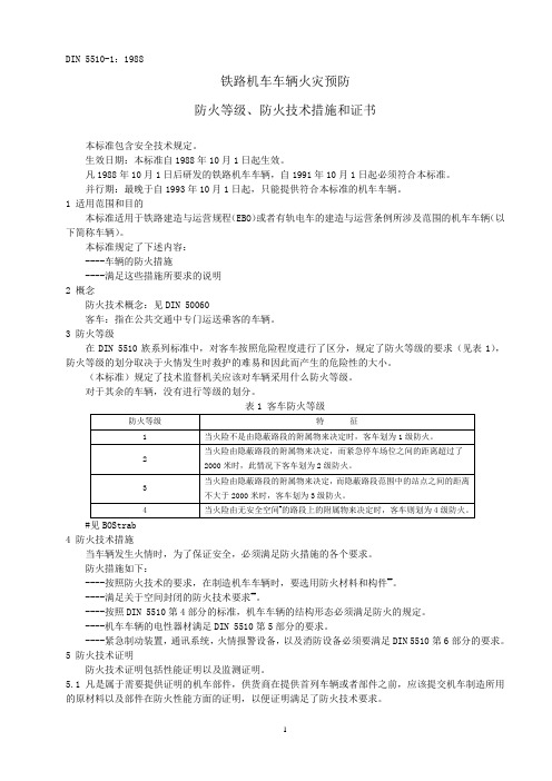
铁路机车车辆火灾预防防火等级、防火技术措施和证书本标准包含安全技术规定。
生效日期:本标准自1988年10月1日起生效。
凡1988年10月1日后研发的铁路机车车辆,自1991年10月1日起必须符合本标准。
并行期:最晚于自1993年10月1日起,只能提供符合本标准的机车车辆。
1 适用范围和目的本标准适用于铁路建造与运营规程(EBO)或者有轨电车的建造与运营条例所涉及范围的机车车辆(以下简称车辆)。
本标准规定了下述内容:----车辆的防火措施----满足这些措施所要求的说明2 概念防火技术概念:见DIN 50060客车:指在公共交通中专门运送乘客的车辆。
3 防火等级在DIN 5510族系列标准中,对客车按照危险程度进行了区分,规定了防火等级的要求(见表1),防火等级的划分取决于火情发生时救护的难易和因此而产生的危险性的大小。
(本标准)规定了技术监督机关应该对车辆采用什么防火等级。
对于其余的车辆,没有进行等级的划分。
#见BOStrab4 防火技术措施当车辆发生火情时,为了保证安全,必须满足防火措施的各个要求。
防火措施如下:----按照防火技术的要求,在制造机车车辆时,要选用防火材料和构件##。
----满足关于空间封闭的防火技术要求##。
----按照DIN 5510第4部分的标准,机车车辆的结构形态必须满足防火的规定。
----机车车辆的电性器材满足DIN 5510第5部分的要求。
----紧急制动装置,通讯系统,火情报警设备,以及消防设备必须要满足DIN 5510第6部分的要求。
5 防火技术证明防火技术证明包括性能证明以及监测证明。
5.1 凡是属于需要提供证明的机车部件,供货商在提供首列车辆或者部件之前,应该提交机车制造所用的原材料以及部件在防火性能方面的证明,以便证明满足了防火技术要求。
此外,他还应该证明,已经按照第4节的要求采取了防火的技术要求。
5.2 监测证明5.1节“性能证明”的要求是否得到满足,需通过监测进行监督。
德标DIN 5510中文阻燃报告
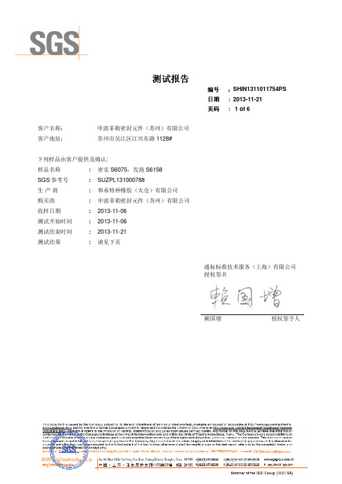
客户名称: 客户地址:
申波菲勒密封元件(苏州)有限公司 苏州市吴江区江兴东路 1128#
下列样品由客户提供及确认:
样品名称
: 密实 S6075;发泡 S6158
SGS 参考号
: SUZPL131000788
生产商
: 和承特种橡胶(太仓)有限公司
购买商
: 申波菲勒密封元件(苏州)有限公司
收样日期
IV. 试验结果 1. 样品A(密实S6075)
1
测试材料被点燃在
(秒)后
40
测试材料继续燃烧
(秒)
0
出现在 (秒)
-
无焰燃烧
持续时间 (秒)
-
火焰高度
最大高度 (厘米)
21
出现时间 (秒)
148
测 试 材 料 滴 落 滴落物 (是/否)
否
物 烟体浓度
燃烧时间 (秒)
-
最大程度 (%)
7
出现时间 (秒)
烧时间>20 s
SR-1
光弱化积分值 ≤ 100 %×min
ST-2 无燃烧的滴落物
SR-2
光弱化积分值 ≤ 50 %×min
陈述:
本试验结果得出的产品性能是在特殊条件下的检验结果。在实际应用中,它们不能单独作为评价该产品
潜在火灾和烟气危险性的依据
本测试结果仅代表被测试试样,成分、厚度等试样的任何微小的变化可能会导致测试结果的巨大变化,
******** 报告结束********
150
光弱化积分 (% X 分)
6
被损毁烧焦区域的长度 (厘米)
14
测试材料熄灭在
(秒)后
-
测试材料被烧穿
DIN5510 BS6853 NFF16101对比分析-11-5
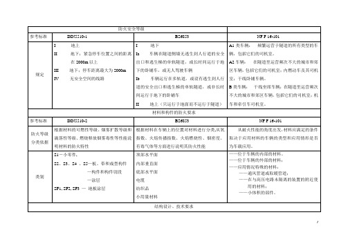
123456①DIN5510 与BS 6853对车辆的安全防火各自作了规定,DIN5510是根据材料的可燃性等级、烟雾扩散等级和滴落性等级、燃烧释放气体毒性等方面说明材料的燃烧特性,DIN5510将地上的防火等级规定为I 级,地下和无安全空间运行的客车等分别分为II~ IV级,而BS6853是以燃烧范围和感觉可能性及起火时可能引起的危险的不同进行等级划分,将地下的情况划分为I类,地上的情况划分为II类②类别划分上,DIN5510和BS6853也各不相同,DIN5510中的分类及各自要求如下:78DIN5510中对于材料的防火等级划分基本上也是基于产品的应用部位,大体可分为顶部、侧墙(侧窗以上)、侧墙(侧窗以下)、底部平面等几个部分,该标准中对于材料或部件的烟毒性也是基于他们不同的应用位置,分别提出了30分钟或15分钟内不对人的生命产生危险,对应气体毒性指标为FE D≤1,检测气体为CO2、CO、HF、HCl、HBr、HCN、NO2、SO2等八种气体,试验标准为DIN EN ISO 5659-2。
BS6853要求30分钟内不对人的生命产生危险,检测气体种类同DIN5510,试验标准为EN 2824、EN2825和EN 2826(大用量体积法)或NF X70-100(小用量质量法),对应气体毒性指标为R值。
③DIN5510 对可燃性等级为S2至S5的部件还要进行烟雾扩散试验(DIN54837),对所有的材料还要进行滴落性等级试验(DIN54837),BS6853对用量在100g~500g之间的小用量材料和用量在400g~2000g之间的小用量材料的可燃温度,含氧量、通过的光密度及有毒气体排放量作出了明确的规定。
④DIN5510对座椅进行试验进行了规定,试样是包括靠背、扶手、头枕的整体原始座椅,试验温度为(20±5)°C,对于用多种材料组成的座椅应开切口检验。
BS6853中,对座椅的背面、椅座及壳体在表面火焰扩散等级、通过的光密度及有毒气体排放量等参数指标作出了明确的规定。
DIN 5510-2C铁路车辆预防燃烧阻燃等级
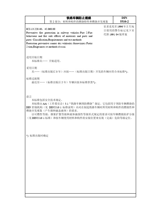
铁路车辆用材料和小构件试验—测定气体燃烧器的燃烧特性。
DIN 66082
织物产品燃烧特性的特微值-幕布材料和窗帘材料。
DIN 66084
枕垫复合材料燃烧特性分类。
DIN 75200
汽车内饰材料燃烧特性测定。
DIN EN 殊性 438-1 装饰用高压—层压材料板(HPL);第 1 部分:技术条件;德语版 EN 438-1:1981
光线减弱整数 无要求 ≤2 500 ≤750
4.3 烟雾扩散等级和试验方法 对于可燃性等级 S2 至 S5,根据要求在燃烧试验时还要附加测定烟雾扩散(按 E DIN 54 837)。 根据烟雾扩散程度按表 3 进行分类。
表3
烟雾扩散等级
光线减弱整数
% x min
SR1
< 100
SR2
< 50
4.4 滴落性等级和试验方法 试验(按 E DIN 54 837)时确定,是否燃烧材料或不燃烧材料有滴落现象。 规定按表面分类。
几处和该文献以后要执行。注明日期的引用资料以后更改时,本标准也应相应更改。末注明日期的引 用资料应采用该文献的最新版本。
DIN 4102-1
建筑材料和构件—建筑材料的燃烧特性。
DIN 4102-14
建筑材料和构件—衬层和底板涂层的燃烧特性;火焰扩散测定。
DIN 5510-1
铁路车辆预防燃烧、燃烧防护等级,燃烧防护技术措施和说明。
3. 概念
第 5 页 E DIN 5510-2:1996-02
3.1 复合材料 复合材料是供货状态的多层材料。
3.2 材料组合 材料组合是装在车辆上时,材料的所有面或部分面相互连接(粘结、焊接、夹紧)或无缝连接(相
互间距离为 20mm)。
5510说明书

(2)起升机构工作前,应通电空载检查,调整制动片与制动轮之间的间隙,再满负荷调整,通电后间隙调整在0.5-1mm之间为宜。
(3)使用前,应检查减速器的油量是否合适,油质是否符合要求,否则必须添加或更换润滑油。
牵引机构
速度
电机型号
功率
转速
40.5/20m/min
YDEJ132S-4/8
3.3/2.2KW
710/1440 r/min
顶升机构
速度
电机型号
功率
转速
工作压力
0.7m/min
Y132S-4
5.5KW
1440 r/min
20MPa
平衡重
臂长55米
14.5t 用七块 2.2t×6+1.3t
臂长50米
13.2t用六块 2.2t×6
6.3、各种安全装置的调整……………………………………………………51
七、塔机的使用与维护保养…………………………………………………56
7.1、塔机的安全使用须知……………………………………………………56
7.2、塔机的维护保养…………………………………………………………57
7.3、塔机的工作条件和工作环境……………………………………………59
3.2、套架………………………………………………………………………15
3.3、回转支承座………………………………………………………………15
3.4、回转塔身节………………………………………………………………16
3.5、司机室……………………………………………………………………16
3.6、塔帽………………………………………………………………………16
DIN6701DIN5510和EN792
DIN6701DIN5510和EN7921988年10月铁路机车车辆预防性防火车辆结构设计安全技术要求DIN德国标准协会铁路机车车辆标准委员会(FSF)DK 629.45:614.841.33本标准包含安全技术规定。
有效性的开始本标准自1988年10月1日起生效。
引入期1988年10月1日以后研制的铁路机车车辆应从1991年10月1日起满足本标准的要求。
过渡期最晚从1993年10月1日起,只有满足本标准要求的铁路机车车辆能够交付。
1 应用范畴和目的本标准适用于在铁路技术治理规程(EBO)或都市有轨电车技术治理规程(BOStrab)适用范畴之内的铁路机车车辆(以下仅称“车辆”)。
在进行车辆结构设计时本标准的用处是:-防止由于技术故障或由于热量没有散出而引起的火灾,-阻止火灾的蔓延或至少延迟火情的蔓延,以及-在归属标准DIN5510第1部分防火等级为1~3的客车中火势完全蔓延的情形下,能使乘客得以自救。
在进行车辆结构设计时,除考虑本标准外还要考虑:a)电气设备的安置(参见标准DIN 5510 第5部分)b)空间封闭的系统的结构*)c)对装可燃气体和液体的设备的要求*)。
*)标准正在制定。
2 对可清洁性的要求车辆的设计应使可燃异物(垃圾、尘土、赃物、制动磨损物、油和油脂)能在定期进行的爱护过程中能够被去除。
采暖、通风和制冷风道的布置应使其在需要时能够进行清洁。
关于防火等级为1~4的客车,在进行车内设计时要注意标准DIN 25 150(目前为草稿)的要求。
3 乘客可进入的客车空间的设计要求3.1 通过观看孔发觉纵火源(针对防火等级为3和4的客车)。
为了能通过观看孔发觉纵火源-在大客室中座椅靠背上方设置透亮的空间隔断。
-设置的客室隔墙应带有能够看到下一个客室情形的观看口。
-带有通过台的车辆,只要不能透过车门看到下一节车辆,没有司机室的端墙侧要设置一个能够看到下一节车内情形的观看口。
3.2 易燃物的安置方式(针对防火等级为2~4的客车)。
德标DIN5510
DIN 5510-2汉宜铁路等轨道火车烟雾和熔滴测试熟悉孙中山先生的人应该都知道,孙中山先生在《建国方略》中提出他的两大宏伟梦想,一是修建三峡大坝,二是建设川汉铁路。
100多年前,承载强国之梦的川汉铁路动议,无奈受技术、财力的制约,一次次被提起,一次次又被搁下。
直到2004年,国家《中长期铁路网规划》出台,汉宜铁路成为沪汉蓉快速大通道的重要组成部分,作为全国铁路网络“四纵四横”中的“一横”,才终于被提上建设日程。
汉宜铁路的身世最早可追溯至川汉铁路。
灵动的汉宜铁路,水墨的江汉平原。
2012年7月1日,汉宜铁路正式开通运营,“和谐号”动车组列车如风飞驰。
使国人的川汉铁路百年长梦今朝圆。
汉宜铁路的正线全长293.1公里。
它东连京广线、武九线、武康线、武广高铁、合武高铁和在建的京石武高铁,西接焦柳线、宜万线,中部连接拟建的蒙西煤运大通道,起着连接南北、承东启西的衔接作用,将推动江汉平原这个湖北省人口最稠密、农业经济最发达的城镇带加速腾飞。
在汉宜铁路上如风飞驰的列车是诞生于2007年的CRH5型动车组,在相同速度等级的动车组中,CRH5型动车组以乘坐空间宽敞、车内空气清新、启动平稳、加速快捷等特点为人熟知。
CRH5型动车组还具有牵引力大、安全可靠、便于维护、环保节能等特点,为铁路用户所青睐。
去年5月,CRH5型动车组首次亮相武汉,承担武汉到北京、武汉到十堰之间的运营,去年一年中,武汉共计迎来了13列CRH5型动车组。
CRH5型动车组良好的运营状况、较长的运行寿命周期以及较低的运营维护成本得到铁路运营部门的肯定。
今年又有16列CRH5型动车组相继进入武汉,并在今年开通的汉宜铁路上承担所有动车运营的职能。
CRH5型动车组最大的特点在于它运行120万公里才需要进行三级修,而相同速度等级的其他动车组运行60万公里就要进行三级修,且CRH5型动车组维修所需的零部件价格要低廉得多。
并且CRH5型动车组载客量为570人,100分钟之内就能跑完汉宜间291.83公里的路程。
DIN 5510 第1部分
DIN 5510 第1部分1988年10月铁路机车车辆预防性防火防火等级、防火技术措施和证明DIN德国标准协会铁路机车车辆标准委员会(FSF)DK 629.45:614.841.33本标准包含安全技术规定。
有效性的开始本标准自1988年10月1日起生效。
引入期1988年10月1日以后研制的铁路机车车辆应从1991年10月1日起满足本标准的要求。
过渡期最晚从1993年10月1日起,只有满足本标准要求的铁路机车车辆可以交付。
1 应用范围和目的本标准适用于在铁路技术管理规程(EBO)或城市有轨电车技术管理规程(BOStrab)适用范围之内的铁路机车车辆(以下仅称“车辆”)。
在本标准中规定了:-铁路机车车辆预防性防火的措施-关于履行该保护措施的必需的证明。
2 概念防火技术概念见标准DIN 50 060。
客车客车是指在公共交通中供乘客按照规定使用的铁路机车车辆。
3 防火等级按照DIN5510标准系列中所包含的要求的危险性的不同,为客车制定了防火等级(见表1)。
防火等级是针对在火灾情况下的逃离可能性和由火灾而造成的危险制订的。
它为技术负责部门规定了哪种车辆使用何种防火等级。
没有按防火等级对其他的车辆进行不同的分级。
在车辆火灾的情况下,为了保证足够的安全性,必须采取预防性防火措施。
这些防火技术措施包括以下措施:- 遵守在制造车辆时,对所使用的材料和零部件**)提出的防火技术要求;-遵守对空间隔断**)的防火技术要求;-遵守标准DIN5510第4部分关于车辆结构设计的防火技术条例-遵守标准DIN5510第5部分对电气设备的有关要求-遵守标准DIN5510第6部分对紧急制动装置的功能、信息系统、火警装置、消防设备的有关要求。
**)标准在制订中。
5 防火技术证明防火技术证明包含合格证明和监督证明。
5.1 合格证明在交付第一辆车或零部件之前,供货者应提交关于遵守制造车辆所使用的材料和零部件防火技术要求的试验证明或试验通知,只要涉及车辆的部件的证明。
- 1、下载文档前请自行甄别文档内容的完整性,平台不提供额外的编辑、内容补充、找答案等附加服务。
- 2、"仅部分预览"的文档,不可在线预览部分如存在完整性等问题,可反馈申请退款(可完整预览的文档不适用该条件!)。
- 3、如文档侵犯您的权益,请联系客服反馈,我们会尽快为您处理(人工客服工作时间:9:00-18:30)。
DIN 5510 第6部分
1988年10月
铁路机车车辆预防性火灾保护
辅助措施
紧急制动装置的功能、信息系统、火警装置、消防设备、安全性要求
有效性的开始
本标准自1988年10月1日起生效。
引入期
1988年10月1日以后研制的铁路机车车辆应从1991年10月1日起满足本标准的要求。
过渡期
最晚从1993年10月1日起,只有满足本标准要求的铁路机车车辆可以交付。
适应期
最晚从1996年10月1日起所有(在运用中的)符合标准DIN5510 第1部分防火等级为3的铁路机车车辆应满足第2款的要求(紧急制动装置)。
标准出版后,所有防火等级为3的车辆必须马上满足第3.1款有关乘客说明的要求,并且所有防火等级为2到4的车辆必须马上满足第5款有关消防设备(灭火器)的要求。
1 应用范围和目的
本标准适用于在铁路技术管理规程(EBO)或城市有轨电车技术管理规程(BOStrab)适用范围之内的铁路机车车辆(以下仅称“车辆”)。
在本标准中规定了铁路机车车辆预防性火灾保护的辅助措施- 紧急制动装置、信息系统、火警装置和消防设备。
2 紧急制动装置
2.1 对于防火等级为2到4的车辆,在特定的线路区段操作紧急制动装置,紧急制动装置不
能自动进行紧急停车,以避免在隧道中以及在救援受限制的线路区段上临时停车。
2.2 对于防火等级为2的车辆,由特殊的行车规章来规定这种线路区段。
2.3 防火等级为3和4的车辆,其紧急制动装置应满足2.
3.1至2.3.4款的要求。
2.3.1 紧急制动装置应具有在停车站以外- 在隧道中和没有安全空间的线路上- 动作时不会自动进行有效紧急制动的特性。
有过渡期的车辆,允许由司机从司机台处将已开始的紧急制动转到无效状态。
2.3.2对于防火等级为3和4的车辆,在停车站以外,以下的情况下紧急制动装置可以动作:
a) 在隧道中,如果列车的头部在紧急停车后可能会进入隧道200m以上,以及列车驶离站
台至少8s。
也可以用在这段时间里一般情况下列车驶过的距离代替时间来作为依据。
b) 在没有安全空间的线路上,如果在紧急停车后该车的乘客不再能够离开列车到站台上。
2.3.3 如果在停车站内紧急制动装置动作,应能立即并且自动避免列车开动或使开动的列车刹车。
有过渡期的车辆,允许由司机进行紧急制动。
2.3.4应使司机,或者在没有司机的行车作业情况下,使配备的工作人员能清楚的识别紧急制动装置的动作。
3 信息系统
3.1 乘客说明
对于还未满足第2款要求的、符合DIN5510第1部分防火等级为3的车辆,在已有的紧急制动装置旁边注明如下说明:
“车辆在隧道中着火或冒烟时:在行车途中不要操作紧急制动装置,等待列车驶入下一个车站并报告车务人员。
”
3.2 乘客信息
如果在操作紧急制动装置后,列车继续行车,则由司机或在没有司机的行车作业情况下,由配备的车务人员通知乘客。
4 火警装置
4.1 防火等级为4的车辆备有自动报警装置。
4.2 火警装置的安排应首先能向司机或固定的配备车务人员(在这种情况下,要说明位置)报告火灾。
4.3 火警装置和附加信息设备的供电应不依赖接触网供电。
4.4 如果通过消防设备的自动触发,断定车辆上发生火灾,那么可以从报警装置上看出。
5 消防设备(灭火器)
5.1 一般要求
使用符合标准DIN14 406第1部分的、可搬动式灭火器。
如果用水作为灭火剂也可以使用许可用于德国铁路的特殊灭火器W8。
供乘客使用的可搬动式灭火器,在使用时应适合于扑灭电气着火。
灭火器应易于拿得到,只要它自身不易被辨认,就要按照标准DIN4066的要求,通过指示牌标明它的位置。
5.2 车辆装备
客车乘客室和机车司机室的车辆装备应遵守如表1所列的最低要求。
有灭火器的其他车辆和乘客室,其其他的装备应按当时占优势的或标准DIN EN2所期望的防火等级进行。
主管监督部门对此作出规定。
表 1 最低要求
6 检查
在交付第1列车之前通过检查、部件和监控元件的功能试验、组装过程中的装配检查、生产材料的检查来保证车辆遵守本标准的要求,按照1988年10月版标准DIN 5510 第1部分5.1款证明合格。
引用标准和其它资料
DIN 4066 防火指示牌
DIN 5510 第1部分铁路机车车辆预防性火灾保护;防火等级、防火技术措施和证明DIN 14 406 第1部分可搬动式灭火器;定义、种类、要求
DIN EN 2 燃烧等级
BOStrab 城市有轨电车技术管理规程
从以下渠道获得:
Einkaufs-und Wirtschaftsgesellschaft für Verkehrbetriebe mbH (Beka) Hamburg Zweigniederlassung Köln
37-39 5000 Köln1
EBO 铁路技术管理规程
从以下渠道获得:
Drucksachenzentrale der Deutschen Bundesbahn Karlsruhe
Stuttgarter Straße 61a
7500 Karlsruhe 1
注释
本标准由UA31“铁路机车车辆预防性火灾保护”制订。
它包含认为对于铁路机车车辆预防性火灾保护(见标准DIN5510第1部分注释)有必要的辅助措施:紧急制动装置的功能以及给车辆配备信息系统、火警装置和消防设备,这些措施在要进行修订的德国标准内。
对于第2款
对着火的列车紧急制动动作后停车于隧道中产生的危险和列车在走行装置有技术问题的情况下继续行车产生的危险,这两方面进行审慎的权衡之后,UA31认为,对于防火等级为2到4的车辆,有必要在着火的情况下不让乘客进行强迫紧急停车。
从德国铁路和公共交通协会(VÖV)短途运输中应用紧急制动得到这样的认识,即防火等级为3的车辆,在停车站内,列车启动阶段紧急制动动作而使列车立即停车是有必要的。
在此基础上为防火等级为3和4的车辆确定了如下保护目标:
--- 在停车站起动范围内,紧急制动动作时应使列车立即自动停车。
--- 列车在停车站之间的隧道中行车期间,紧急制动动作时不得使车辆停车。
UA31对紧急制动装置的功能规定了必须的、最低要求。
紧急制动装置是实现保护目的所必须的,可以采用各种技术方案。
对于第3.1款
也考虑过防火等级为2的车辆,在火灾情况下进行紧急制动的乘客说明。
然而没有规定,因为在相邻两个较长隧道间距离短的情况下,车辆离开一条隧道后,如果操作紧急制动装置还会造成车辆在下一条隧道中停车。
对于第5款
还没有确定对自动消防设备(例如自动灭火装置)的要求。
为此需要在研究计划内结束对这种措施的效果的检验。
