P304中文资料
创维电视存储器数据说明
2、AV时为YDAV 07 可固定
PE-2:
一、 FOR 无信号场频 (Ver1.30) 03(50Hz) 可固定
注:Ver1.31 板本时,为V-FOR ,其高位为AV伴音付音量,非标时用。
二、 VG2-B 调帘栅时的亮度值 30 配管定
三、 RPO 勾边幅度 03 主观评价定
Bit 0 X射线保护*/ (0-有 1-无) 0
Bit 1 自动音量*/ (0-无 1-有) 0
Bit 2 强制彩色制式*/ (0-自动 1-强制) 0
Bit 3 转台模式*/ (0-无 1-有) 1
Bit 4 功放选择*/ (0-TDA2126 1-TDA7057) 0
Bit 5 中频锁相环*/ (0-标准 1-快速) 0
Bit 5 信号识别方式*/ 1
Bit 6 信号识别方式*/ 0
Bit 7 N制矩阵选择*/ (0-美国制式 1-日本制式) 0
行、场线性(包括N制)也需重调。维修时这些数据可从同类型的正常机器中抄录下来,再输入到该维修机中。
3、初始化后,重新进入该项,其显示变为00。
4、在以下两种情况下用。
1)售后维修时,如果出现不存台,且进入维修菜单各项不可调等现象,则可能是存储器数据中版本号丢失,需初始化。
2)装上全新存储器,或其它数据的旧存储器时,需初始化。
V-AMP 33 3F (参考值) 场幅
V-SC 23 3F (参考值) 场线性
以上各项都是常见参数调整,这里不作特别说明。但要注意此机芯NTSC和PAL信号的场参数必须分开各自调整。
2.线性枕校、梯形调整菜单:(此菜单下的所有项目不用作调整)
SER50HZ
《儿童发展心理学》期末重点·打印版

《⼉童发展⼼理学》期末重点·打印版<⽬录>【简答题】1.关于遗传与环境之争(阶段+代表⼈物)p82.相互作⽤论的基本观点p103.⼉童发展⼼理学的主要研究⽅法(含义+优缺点)p304.⼉童动作发展的规律p555.评定新⽣⼉感觉的⼏种⽅法p626.⽪亚杰的认知发展阶段论p867.⼉童使⽤形容词的发展过程有何特点p132---新的内容(7.⼉童话语发展特点p133)8.简述“单词句”(含义+特点)p1359.句⼦的理解策略有什么P13810.语⾔获得相互作⽤论的主要观点(Piaget)p14611.良好的情绪或健康的情绪的特征p173--新的内容12.情绪发展的总趋势p18213.影响怯⽣的因素(定义+影响因素)p18314.玛西娅的同⼀性发展理论p22115.性别恒常性(性别⼀致性)发展要经历的三阶段p22516.什么是依恋(定义+类型)p24317.早期依恋对⼉童发展的影响p25218.缪勒和⽩莱纳把婴⼉同伴相互作⽤划分为三阶段(同伴的作⽤)p25619.⽪亚杰的⼉童道德认知发展三阶段p27420.⼉童观察⼒发展的⼤致趋势p75(⽼师补充的)21.思维(认识)的起源发展p7822.⼉童话语发展的特点p123(⽼师补充的)【论述】1.关于遗传与环境之争(阶段+代表⼈物+主要观点+对教育的启发)p82.⼉童发展⼼理学的主要研究⽅法(含义+优缺点)p303.“视崖”实验(⽬的+结果+结论)p764.⽪亚杰的认知发展阶段论(+评价p93)p865.论述⽪亚杰对⼈类思维的起源、结构和机制的看法,以及你对该理论的评价。
(⽼师补充的)6.语⾔获得理论(有什么+代表⼈物+观点)p1447.埃⾥克森⼈格发展阶段理论与弗洛伊德⼈格发展阶段理论的区别p1968.论述埃⾥克森的“⼼理社会发展的阶段”p1979.简评埃⾥克森的⼈格发展理论p20010.影响个性形成的主要因素p20211.论述⽪亚杰的⼉童道德认知发展的三个阶段p27412.柯尔伯格(Kohlberg)的⼉童道德认知发展理论(三⽔平六阶段名称+特点)p277【简答题】1.关于遗传与环境之争(阶段+代表⼈物)p8这场争论⼤致经历了三个阶段:1)绝对决定论:争论的双⽅把遗传与环境完全对⽴起来。
HD74LS04P中文资料
HD74LS04 / HD74LS05Hex Inverters / Hex Inverters (with Open Collector Outputs)REJ03D0391–0300Rev.3.00Jul.13.2005 Features• Ordering Information• HD74LS04Part Name Package Type Package Code(Previous Code)PackageAbbreviationTaping Abbreviation(Quantity)HD74LS04P DILP-14pin PRDP0014AB-B(DP-14AV)P —HD74LS04FPEL SOP-14 pin (JEITA) PRSP0014DF-B(FP-14DAV)FP EL (2,000 pcs/reel)HD74LS04RPEL SOP-14 pin (JEDEC) PRSP0014DE-A(FP-14DNV)RP EL (2,500 pcs/reel)• HD74LS05Part Name Package Type Package Code(Previous Code)PackageAbbreviationTaping Abbreviation(Quantity)HD74LS05P DILP-14pin PRDP0014AB-B(DP-14AV)P —HD74LS05FPEL SOP-14 pin (JEITA) PRSP0014DF-B(FP-14DAV)FP EL (2,000 pcs/reel)HD74LS05RPEL SOP-14 pin (JEDEC) PRSP0014DE-A(FP-14DNV)RP EL (2,500 pcs/reel)Note: Please consult the sales office for the above package availability. Pin ArrangementCircuit Schematic (1/6)Absolute Maximum RatingsUnitRatingsItem SymbolSupply voltage V CC Note 7 VInput voltage V IN 7 V Power dissipation P T 400 mW Storage temperature Tstg –65 to +150 °CNote: Voltage value, unless otherwise noted, are with respect to network ground terminal.Recommended Operating Conditions• HD74LS04MaxUnitMinTypItem SymbolSupply voltage V CC 4.75 5.00 5.25 VI OH — — –400 µAOutput currentI OL — — 8 mA°C2575Operating temperature Topr–20• HD74LS05MaxUnitTypMinItem SymbolSupply voltage V CC 4.75 5.00 5.25 VOutput voltage V OH — — 5.5 VOutput current I OL — — 8 mA°C7525–20Operating temperature ToprElectrical Characteristics• HD74LS04(Ta = –20 to +75 °C)ItemSymbol min. typ.* max. Unit Condition V IH 2.0 — — V Input voltageV IL — — 0.8 V V OH 2.7 — — V V CC = 4.75 V, V IL = 0.8 V, I OH = –400 µA— — 0.5 I OL = 8 mAOutput voltageV OL— — 0.4 V I OL = 4 mAV CC = 4.75 V, V IH = 2 V I IH — — 20 µA V CC = 5.25 V, V I = 2.7 V I IL — — –0.4 mA V CC = 5.25 V, V I = 0.4 VInput current I I — — 0.1 mA V CC = 5.25 V, V I = 7 V Short-circuit outputcurrent I OS –20— –100 mA V CC = 5.25 V I CCH — 1.2 2.4 mA V CC = 5.25 VSupply currentI CCL — 3.6 6.6 mA V CC = 5.25 VInput clamp voltage V IK — — –1.5 V V CC = 4.75 V, I IN = –18 mA Note: * V CC = 5 V, Ta = 25°C• HD74LS05(Ta = –20 to +75 °C)ItemSymbol min. typ.* max. Unit Condition V IH 2.0 — — VInput voltageV IL — — 0.8 V— — 0.5 I OL = 8 mAOutput voltage V OL — — 0.4 V I OL = 4 mAV CC = 4.75 V, V IH = 2 VOutput current I OH — — 100 µA V CC = 4.75 V, V IL = 0.8 V, V OA = 5.5 VI IH — — 20 µA V CC = 5.25 V, V I = 2.7 VI IL — — –0.4 mA V CC = 5.25 V, V I = 0.4 VInput current I I —— 0.1 mA V CC = 5.25 V, V I = 7 V I CCH — 1.2 2.4 mA V CC = 5.25 VSupply currentI CCL —3.6 6.6 mA V CC = 5.25 V Input clamp voltage V IK — — –1.5 V V CC =4.75 V, I IN = –18 mA Note: * V CC = 5 V, Ta = 25°CSwitching Characteristics• HD74LS04(V CC = 5 V, Ta = 25°C)Item Symbol min. typ. max. Unit Conditiont PLH — 9 15 nsPropagation delay timet PHL — 10 15 ns C L = 15 pF, R L = 2 k Ω• HD74LS05(V CC = 5 V, Ta = 25°C)Item Symbol min. typ. max. Unit Conditiont PLH — 17 32 nsPropagation delay time t PHL — 15 28 nsC L = 15 pF, R L = 2 k ΩNote: Refer to Test Circuit and Waveform of the Common Item "TTL Common Matter (Document No.: REJ27D0005-0100)".Package Dimensions RENESAS SALES OFFICESRefer to "/en/network" for the latest and detailed information.Renesas Technology America, Inc.450 Holger Way, San Jose, CA 95134-1368, U.S.ATel: <1> (408) 382-7500, Fax: <1> (408) 382-7501Renesas Technology Europe LimitedDukes Meadow, Millboard Road, Bourne End, Buckinghamshire, SL8 5FH, U.K.Tel: <44> (1628) 585-100, Fax: <44> (1628) 585-900Renesas Technology Hong Kong Ltd.7th Floor, North Tower, World Finance Centre, Harbour City, 1 Canton Road, Tsimshatsui, Kowloon, Hong KongTel: <852> 2265-6688, Fax: <852> 2730-6071Renesas Technology Taiwan Co., Ltd.10th Floor, No.99, Fushing North Road, Taipei, TaiwanTel: <886> (2) 2715-2888, Fax: <886> (2) 2713-2999Renesas Technology (Shanghai) Co., Ltd.Unit2607 Ruijing Building, No.205 Maoming Road (S), Shanghai 200020, ChinaTel: <86> (21) 6472-1001, Fax: <86> (21) 6415-2952Renesas Technology Singapore Pte. Ltd.1 Harbour Front Avenue, #06-10, Keppel Bay Tower, Singapore 098632Tel: <65> 6213-0200, Fax: <65> 6278-8001Renesas Technology Korea Co., Ltd.Kukje Center Bldg. 18th Fl., 191, 2-ka, Hangang-ro, Yongsan-ku, Seoul 140-702, KoreaTel: <82> 2-796-3115, Fax: <82> 2-796-2145Renesas Technology Malaysia Sdn. Bhd.Unit 906, Block B, Menara Amcorp, Amcorp Trade Centre, No.18, Jalan Persiaran Barat, 46050 Petaling Jaya, Selangor Darul Ehsan, MalaysiaTel: <603> 7955-9390, Fax: <603> 7955-9510。
四乙基氢氧化铵 化学品安全技术说明书

化学品安全技术说明书产品名称: 四乙基氢氧化铵按照GB/T 16483、GB/T 17519 编制修订日期: 2019年7月15日版本: 1.0最初编制日期: 2019年7月15日第1部分化学品及企业标识化学品中文名:四乙基氢氧化铵化学品英文名: Tetraethylammonium hydroxide产品编号: -企业名称:上海百舜生物科技有限公司企业地址:上海奉贤区柘林镇联业路918弄26号邮编: 201400传真:联系电话:电子邮件地址:企业应急电话:产品推荐及限制用途:工业及科研用途。
第2部分危险性概述紧急情况概述:可能腐蚀金属。
吞咽有害。
皮肤接触会中毒。
造成严重皮肤灼伤和眼损伤。
造成严重眼损伤。
对器官造成损害。
长期或反复接触会对器官造成伤害。
GHS危险性类别:金属腐蚀物类别 1急性经口毒性类别 4急性经皮肤毒性类别 3皮肤腐蚀 / 刺激类别 1B严重眼损伤 / 眼刺激类别 1特异性靶器官毒性一次接触类别 1特异性靶器官毒性反复接触类别 1标签要素:象形图:警示词:危险危险性说明:H290 可能腐蚀金属H302 吞咽有害H311 皮肤接触会中毒H314 造成严重皮肤灼伤和眼损伤H318 造成严重眼损伤H370 对器官造成损害H372 长期或反复接触会对器官造成伤害防范说明:预防措施:—— P234 只能在原容器中存放。
—— P264 作业后彻底清洗。
—— P270 使用本产品时不要进食、饮水或吸烟。
—— P280 戴防护手套/穿防护服/戴防护眼罩/戴防护面具。
—— P260 不要吸入粉尘/烟/气体/烟雾/蒸气/喷雾。
事故响应:—— P390 吸收溢出物,防止材料损坏。
—— P301+P312 如误吞咽:如感觉不适,呼叫解毒中心/ 医生—— P330 漱口。
—— P302+P352 如皮肤沾染:用水充分清洗。
—— P312 如感觉不适,呼叫解毒中心/医生—— P321 具体治疗 ( 见本标签上的…… )。
3-三氟甲基苯胺-危险化学品安全技术说明书中文MSDS文档16个部分(完整版)
化学品安全技术说明书3-三氟甲基苯胺第一部分化学品及企业标识化学品中文名:3-三氟甲基苯胺化学品英文名:3-aminobenzotrifluoride;3-(trifluoromethyl)aniline供应商名称:哈尔滨****化工有限公司供应商地址:哈尔滨**区**路**号**室供应商电话:3426-58****69邮编:245**8供应商传真:3426-58****64电子邮件地址:8888**************产品推荐及限制用途:用于有机合成及染料中间体。
第二部分危险性概述紧急情况概述:可燃液体,吞咽有害,皮肤接触有害,吸入致命,造成皮肤刺激,造成严重眼损伤,对水生生物有毒并具有长期持续影响。
GHS危险性类别:急性毒性-吸入-类别2;皮肤腐蚀/刺激-类别2;严重眼损伤/眼刺激-类别1;危害水生环境-急性危害-类别2;危害水生环境-长期危害-类别2标签要素:象形图:警示词:危险危险信息:H330:吸入致命H315:造成皮肤刺激H318:造成严重眼损伤H411:对水生生物有毒并具有长期持续影响防范说明:预防措施:P260:不要吸入粉尘/烟/气体/烟雾/蒸气/喷雾。
P271:只能在室外或通风良好之处使用。
P284:戴呼吸防护装置。
P264:作业后彻底清洗……。
P280:戴防护手套/穿防护服/戴防护眼罩/戴防护面具。
P273:避免释放到环境中。
应急响应:P304+P340:如误吸入:将受害人转移到空气新鲜处,保持呼吸舒适的休息姿势。
P310:立即呼叫解毒中心/医生。
P320:紧急具体治疗(见本标签上的.....)。
P302+P352:如皮肤沾染:用大量肥皂和水清洗。
P321:具体治疗(见本标签上的.....)。
P332+P313:如发生皮肤刺激:求医/就诊。
P362+P364:脱掉所有沾染的衣服,清洗后方可重新使用。
P305+P351+P338:如进入眼睛:用水小心冲洗几分钟。
如戴隐形眼镜并可方便地取出,取出隐形眼镜。
ISO IEC 80079-34 (中文)
爆炸性环境 —
第 34 部分:设备制造商质量体系应用
1 范围
1.1 通则
本部分 ISO/IEC 80079 规定特殊要求和信息用于建立和保持按照 Ex 证书制 造包括防爆系统的 Ex 设备的质量体系。
但并不排除使用与 ISO 9001:2008 的目标兼容的,并且提供等效结果的其 他质量体系。
2 引用标准
的文件。equipment 在使用部门称之为设备,在制造商内称之为产品。
b) 文件化的程序应确保制造商文件中包含的信息与产品文件兼容。制造 商不应初始批准或尔后修改相关图样,除非它们与目录中图样一致。
c) 质量体系应确保在 Ex 证书和技术文件(例如目录中的图样)中规定的 要素(类型、特征,位置等)不被修改。
ISO 9001:2008 标准 4.2.1 条适用。 4.2.2 质量手册
ISO 9001:2008 标准 4.2.2 条适用。 4.2.3 文件控制
ISO 9001:2008 标准 4.2.3 条适用,具有下列增加: a) 设备文件和制造商的文件应受控制。
译者注:原文 “equipment documents” 设备文件,在本文件中是指被认证的产品
ISO IEC
国际 标准
ISO/IEC 80079-34
第1.0版 2011-04
爆炸性环境 —
第34部分:设备制造商质量体系应用
I
目次
前言 引言 1 范围 2 引用标准 3 术语和定义 4 质量管理体系要求
4.1 总要求 4.2 文件要求
4.2.1 总则 4.2.2 质量手册 4.2.3 文件控制 4.2.4 记录控制 5 管理职责 5.1 管理承诺 5.2 以顾客为关注焦点 5.3 质量方针 5.4 策划 5.4.1 质量目标 5.4.2 质量管理体系策划 5.5 职责、权限与沟通 5.5.1 职责与权限 5.5.2 管理者代表 5.5.3 内部沟通 5.6 管理评审 5.6.1 总则 5.6.2 评审输入 5.6.3 评审输出 6 资源管理 6.1 资源提供 6.2 人力资源 6.3.1 总则 6.2.2 能力、培训和意识 6.3 基础设施 6.4 工作环境 7 产品实现 7.1 产品实现的策划 7.2 与顾客有关的过程 7.2.1 与产品有关要求的确定 7.2.2 与产品有关要求的评审 7.2.3 顾客沟通
江苏译林英语9上Unit 1-4课文翻译

9上Unit 1-4课文翻译姓名:_______________ 9AU1 Comic strip—埃迪,这是一篇有趣的关于性格的文章。
—哦?让我看看。
—它说有些人很慷慨。
他们感觉与其他人分享东西很好。
—对,我同意。
—我很慷慨。
—是的,你是。
—霍波,你把我的早餐吃光了 ! —但这会让你感觉很好啊!9AU1 Welcome to the Unit1.Suzy很有条理。
她把所有的东西都整理得井井有条。
2. Daniel很聪明,但他很谦虚且从不炫耀。
3. 吴老师足够耐心,为我们重复语法规则。
4. Samuel很有创造力。
他经常想到新主意。
5. Billy对一切都很好奇。
他喜欢问问题。
6. Simon很有活力。
他总是成小时地踢球。
米莉:我很有耐心,不轻易生气。
我认为我会是一名好老师或者一名好医生。
你呢,保罗?保罗:我有时候很粗心。
我父母和我都认为我不能做一名好会计,你喜欢什么工作,桑迪?桑迪:我的美木老师说我经常有令人兴奋的主意。
我喜欢创造性的工作。
你呢,戴维?戴维:我很活跃,我喜欢与人交谈。
对于我来说,整天工作而不说话很可怕。
9AU1 Reading吴维,艺术家:“吴维是一位天生的艺术家,”他最好的朋友说。
“他很安静,话不多,但是他的作品却极具说服力!”吴维——年轻的艺术家,他富有创造力的作品给全国留下了很深的印象。
他给阳光镇广场做的雕塑赢得了艺术协会的高度赞扬。
他说:“我想与人们分享最好的艺术,因此我总是搜索一些更好的或不同的东西。
这本身就是非常有趣的事。
”苏宁,经理:五年前,苏宁放弃了她的会计工作,并开始在一家大公司的销售部门工作。
“我活跃并且精力充沛,我喜欢和人们在一起工作。
然而,在我的上一份工作中,我只能日复一日地跟数字打交道。
那使我不开心。
”现在苏宁是这家公司的总经理。
她说:“人生就像一场赛跑。
你要么领先要么落后。
我随时准备好迎接新的挑战。
”刘浩,工程师:刘浩是阳光镇到天津这段高速公路的首席工程师。
2904_中文资料
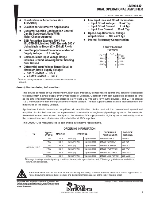
PACKAGING INFORMATION Orderable DeviceStatus (1)Package Type Package Drawing Pins Package Qty Eco Plan (2)Lead/Ball Finish MSL Peak Temp (3)LM2904AVQDRQ1ACTIVE SOIC D 82500Pb-Free (RoHS)CU NIPDAU Level-2-250C-1YEAR/Level-1-235C-UNLIM LM2904AVQPWRQ1ACTIVE TSSOP PW 82000None CU NIPDAU Level-1-250C-UNLIM LM2904QDRQ1ACTIVE SOIC D 82500Pb-Free (RoHS)CU NIPDAU Level-2-250C-1YEAR/Level-1-235C-UNLIM LM2904QPWRQ1ACTIVE TSSOP PW 82000None CU NIPDAU Level-1-250C-UNLIM LM2904VQDRQ1ACTIVE SOIC D 82500Pb-Free (RoHS)CU NIPDAU Level-2-250C-1YEAR/Level-1-235C-UNLIM LM2904VQPWRQ1ACTIVE TSSOP PW 82000None CU NIPDAU Level-1-250C-UNLIM (1)The marketing status values are defined as follows:ACTIVE:Product device recommended for new designs.LIFEBUY:TI has announced that the device will be discontinued,and a lifetime-buy period is in effect.NRND:Not recommended for new designs.Device is in production to support existing customers,but TI does not recommend using this part in a new design.PREVIEW:Device has been announced but is not in production.Samples may or may not be available.OBSOLETE:TI has discontinued the production of the device.(2)Eco Plan -May not be currently available -please check /productcontent for the latest availability information and additional product content details.None:Not yet available Lead (Pb-Free).Pb-Free (RoHS):TI's terms "Lead-Free"or "Pb-Free"mean semiconductor products that are compatible with the current RoHS requirements for all 6substances,including the requirement that lead not exceed 0.1%by weight in homogeneous materials.Where designed to be soldered at high temperatures,TI Pb-Free products are suitable for use in specified lead-free processes.Green (RoHS &no Sb/Br):TI defines "Green"to mean "Pb-Free"and in addition,uses package materials that do not contain halogens,including bromine (Br)or antimony (Sb)above 0.1%of total product weight.(3)MSL,Peak Temp.--The Moisture Sensitivity Level rating according to the JEDECindustry standard classifications,and peak solder temperature.Important Information and Disclaimer:The information provided on this page represents TI's knowledge and belief as of the date that it is provided.TI bases its knowledge and belief on information provided by third parties,and makes no representation or warranty as to the accuracy of such information.Efforts are underway to better integrate information from third parties.TI has taken and continues to take reasonable steps to provide representative and accurate information but may not have conducted destructive testing or chemical analysis on incoming materials and chemicals.TI and TI suppliers consider certain information to be proprietary,and thus CAS numbers and other limited information may not be available for release.In no event shall TI's liability arising out of such information exceed the total purchase price of the TI part(s)at issue in this document sold by TI to Customer on an annual basis.PACKAGE OPTION ADDENDUM 4-Mar-2005Addendum-Page 1IMPORTANT NOTICETexas Instruments Incorporated and its subsidiaries (TI) reserve the right to make corrections, modifications, enhancements, improvements, and other changes to its products and services at any time and to discontinue any product or service without notice. Customers should obtain the latest relevant information before placing orders and should verify that such information is current and complete. All products are sold subject to TI’s terms and conditions of sale supplied at the time of order acknowledgment.TI warrants performance of its hardware products to the specifications applicable at the time of sale in accordance with TI’s standard warranty. T esting and other quality control techniques are used to the extent TI deems necessary to support this warranty. Except where mandated by government requirements, testing of all parameters of each product is not necessarily performed.TI assumes no liability for applications assistance or customer product design. Customers are responsible for their products and applications using TI components. T o minimize the risks associated with customer products and applications, customers should provide adequate design and operating safeguards.TI does not warrant or represent that any license, either express or implied, is granted under any TI patent right, copyright, mask work right, or other TI intellectual property right relating to any combination, machine, or process in which TI products or services are used. Information published by TI regarding third-party products or services does not constitute a license from TI to use such products or services or a warranty or endorsement thereof. Use of such information may require a license from a third party under the patents or other intellectual property of the third party, or a license from TI under the patents or other intellectual property of TI.Reproduction of information in TI data books or data sheets is permissible only if reproduction is without alteration and is accompanied by all associated warranties, conditions, limitations, and notices. Reproduction of this information with alteration is an unfair and deceptive business practice. TI is not responsible or liable for such altered documentation.Resale of TI products or services with statements different from or beyond the parameters stated by TI for that product or service voids all express and any implied warranties for the associated TI product or service and is an unfair and deceptive business practice. TI is not responsible or liable for any such statements. Following are URLs where you can obtain information on other Texas Instruments products and application solutions:Products ApplicationsAmplifiers Audio /audioData Converters Automotive /automotiveDSP Broadband /broadbandInterface Digital Control /digitalcontrolLogic Military /militaryPower Mgmt Optical Networking /opticalnetwork Microcontrollers Security /securityTelephony /telephonyVideo & Imaging /videoWireless /wirelessMailing Address:Texas InstrumentsPost Office Box 655303 Dallas, Texas 75265Copyright 2005, Texas Instruments Incorporated。
RF3404;中文规格书,Datasheet资料

TO39-3 Case•Ideal Front-End Filter for European Wireless Receivers •Low-Loss, Coupled-Resonator Quartz Design •Simple External Impedance Matching •Rugged TO39 Hermetic Package•Complies with Directive 2002/95/EC (RoHS)The RF3404 is a low-loss, compact and economical surface-acoustic-wave (SAW) filter designed to provide front-end selectivity in 433.92MHz receivers. Receiver designs using this filter include superhet with 10.7MHz or 500kHz IF, direct conversion and superregen. Typical applications of these receivers are wireless remote-control and security devices operating in Europe under ETSI I-ETS 300 220.This coupled-resonator filter (CRF) uses selective null placement to provide suppression, typically greater than 40 dB, of the LO and image spurious responses of superhet receivers with 10.7 MHz IF. RFM’s advanced SAW design and fabrication technology is utilized to achieve high performance and very low loss with simple external impedance matching (not included). Quartz construction provides excellent frequency stability over a wide temperature range.433.92 MHzSAW FilterRF3404CAUTION: Electrostatic Sensitive Device. Observe precautions for handling.Notes:1.Unless noted otherwise, all measurements are made with the filter installed in the specified test fixture which is connected to a 50 Ω test system with VSWR ≤ 1.2:1. The test fixture L and C are adjusted for minimum insertion loss at the filter center frequency, f c . Note that insertion loss, bandwidth, and passband shape are dependent on the impedance matching component values and quality. 2.The frequency f c is defined as the midpoint between the 3dB frequencies.3.Where noted, specifications apply over the entire specified operating temperature range.4.The turnover temperature, T O , is the temperature of maximum (or turnover) frequency, f o . The nominal frequency at any case temperature, T c , may be calculated from: f =f o [1-FTC (T o -T c )2].5.Frequency aging is the change in fc with time and is specified at +65°C or less. Aging may exceed the specification for prolonged temperatures above +65°C. Typically, aging is greatest the first year after manufacture, decreasing significantly in subsequent years.6.The design, manufacturing process, and specifications of this device are subject to change without notice.7.One or more of the following U.S. Patents apply: 4,54,488, 4,616,197, and others pending.8.All equipment designs utilizing this product must be approved by the appropriate government agency prior to manufacture or sale.Electrical Characteristics CharacteristicSymNotesMinimum TypicalMaximumUnitsCenter Frequency at 25°C Absolute Frequency f c 1, 2433.92MHz Tolerance from 433.92 MHz∆f C ±80kHz Insertion Loss IL 1 3.55.0dB 3 dB Bandwidth BW 31, 2500600800kHz Rejectionat f c - 21.4 MHz (Image)14050dBat f c - 10.7 MHz (LO)1530Ultimate80TemperatureOperating Case Temp.T C 3, 4-40+85°C Turnover Temperature T O 152540°C Turnover Frequency f O f cMHz Freq. Temp. CoefficientFTC0.032ppm/°C 2Frequency Aging Absolute Value during the First Year |fA|5≤10ppm/yr External ImpedanceSeries Inductance L 147nH Shunt CapacitanceC11pFLid Symbolization (in addition to Lot and/or Date Codes)RFM RF3404PbAbsolute Maximum Ratings Typical Filter ResponseTypical filter responses are shown below. The actual response isdependent on external impedance matching and circuit layout. Illustrated frequencies and minimum rejection for LO and IMAGE are shown only for superhet receivers with 10.7 MHz IF.Electrical ConnectionsTypical Test CircuitCase DesignRatingValueUnitsIncident RF Power+13dBm DC Voltage Between Any Two Pins (Observe ESD Precautions)±30VDC Case Temperature 5-40 to +85°C Soldering Temperature (10 seconds/5 cycles Max)260°CPinConnection1Input or Output 2Output or Input 3Case GroundDimensionsMillimeters Inches MinMaxMinMaxA9.400.370B 3.180.125C 2.503.500.0980.138D 0.46 Nominal 0.018 NominalE 5.08 Nominal 0.200 NominalF 2.54 Nominal 0.100 NominalG 2.54 Nominal0.100 NominalH 1.020.040J1.400.055分销商库存信息: RFMRF3404。
PDA TR34文件中文

医疗保健产品生产和检测用隔离系统的设计和验证PDA 技术报告34号2001年9/10月1.0 引言1.1前言近年来,隔离技术迅速出现,作为一种可供选择的人造环境广泛应用于多种医疗保健产品的生产和检测。
隔离系统的性能特征使其可以很理想的用于无菌产品的制备,以及活性物质的隔离。
其它的应用还有临床准备、无菌散装药品/生物制剂、无菌细胞毒素物质的制备,以及无菌检测。
该技术目前没有权威的应用和验证指导,而且关于“隔离系统”和“阻隔器”的概念严重混淆,这是PDA发布此文件的根本动机。
本文件是由美国PDA、日本PDA、A3P、注射药物协会、和德国代表组成的国际委员会制定的。
本文件可用作指导原则;并不作为强制或暗示的标准。
1.2范围本技术报告给出了在医疗保健产品制造工业的生产、开发、检测中广泛应用隔离技术的基本要求。
本技术报告不仅包括产品的无菌保证,也包括了危险物料的隔离。
术语表(附录A)是本技术报告的一个重要组成部分。
医疗保健行业目前没有一整套关于隔离技术的定义。
委员会认为,为了阐述有用的技术信息,我们必须保证读者在应用该技术报告时没有概念的混淆。
委员会也承认在世界的一些地区,在临床制药设备中经过处理的环境条件都叫做“隔离系统”,这些装置与本文定义的隔离系统有着共同的基本特征,然而,它们与现在医疗保健工业中使用的、用于无菌产品的生产和检测的隔离系统有着显著区别。
本技术报告不适用于不符合本文规定和解释的基本标准的设备。
1.3关键定义建立清晰的划分标准来区分是否是隔离系统对于理解本文至关重要。
PDA建议以下关于隔离系统的定义应被全世界医疗保健行业采纳:隔离系统是密封的或者有微生物过滤系统(高效过滤系统HEPA)提供空气并且可以自净化(1)。
当密闭时,仅使用已净化过的内部表面或使用快速传递通道进行物料传递。
当打开时,仅允许物料通过特定的并已经过设计和验证的开口进行进出传递,以排出污染的传递。
它可被用于无菌操作时隔离活性混合物的或者同时用于灭菌处理和隔离。
潮流网络 GXV34X0 用户手册说明书

深圳市潮流网络技术有限公司GXV34X0系列企业级(高端)高清视频话机用户手册技术支持深圳市潮流网络技术有限公司为客户提供全方位的技术支持。
您可以与本地代理商或服务提供商联系,也可以与公司总部直接联系。
地址:深圳市南山区科技园高新北区酷派大厦C座14层邮编:518057网址:客服电话:*************客服传真:*************技术支持热线:4008755751技术支持论坛:/forums网上问题提交系统:/support/submit-a-ticket商标注明和其他潮流网络商标均为潮流网络技术有限公司的商标。
本文档提及的其他所有商标或注册商标,由各自的所有人拥有。
注意由于产品版本升级或其他原因,本文档内容会不定期进行更新。
除非另有约定,本文档仅作为使用指导,本文档中的所有陈述、信息和建议不构成任何明示或暗示的担保。
更改日志这一部分记录了GXV34X0用户指南以前版本的重大变化。
这里只列出了主要的新特性或主要的文档更新。
修改或编辑的次要更新没有记录在这里。
固件1.0.1.6版产品名称:GXV3480/GXV3450这是初始版本。
固件版本1.0.0.6产品名称:GXV3470这是初始版本。
目录欢迎 (10)产品概述 (10)功能亮点 (10)技术规格 (11)入门 (18)设备包装 (18)GXV34X0外观介绍 (20)连接和设置GXV34X0 (28)使用话机支架 (28)使用插槽安装在墙上 (29)连接GXV34X0 (30)清理话机 (31)了解GXV34X0 (32)使用触摸屏 (32)使用桌面 (34)桌面菜单 (34)添加小工具到桌面 (35)管理桌面项目 (35)设置壁纸 (37)设置可编程的关键部件 (37)可编程键状态 (38)管理运行的应用程序 (41)空闲屏幕 (41)设置主屏幕 (42)添加/删除空闲屏幕 (43)使用状态栏 (44)状态栏中的通知 (46)使用GXV34X0按键 (48)截图 (50)硬复位 (50)使用屏幕键盘 (51)消息指示灯 (52)拨打电话 (53)注册SIP帐户 (53)帐户状态 (53)配置SIP帐户 (53)直接拨号 (54)重拨 (55)使用通讯录拨打电话 (55)通过通话记录拨号 (56)接听电话 (57)单一来电 (57)来电转移 (58)呼叫进展状态 (59)呼叫保持 (60)静音 (61)视频通话转成语音通话 (61)通话时切换音频频道 (62)呼叫转接 (63)指定转接 (64)通过MPKs转移 (65)设置虚拟背景 (66)多方会议 (67)启动会议 (67)删除会议成员 (69)结束会议 (69)保持和恢复会议 (70)多播分页 (70)多播监听开关 (70)UCM会议 (71)加入UCM会议室 (71)电话会议菜单 (71)未接来电 (72)免打扰(DND) (73)呼叫功能 (76)联系人 (78)本地联系人 (78)添加单个联系人 (78)导入/导出联系人 (79)下载联系人 (81)查找联系人 (81)使用联系人 (82)通过联系人发起呼叫 (82)将联系人添加到收藏夹 (82)编辑联系人 (83)发送联系人快捷键到桌面 (83)通过蓝牙共享联系人 (83)添加黑名单 (84)添加分组 (84)将联系人添加到分组中 (84)联系人储存状态 (84)状态检测 (85)通用检测 (85)音频检测 (86)骚扰拦截 (87)拦截联系人 (87)拦截记录 (88)拦截匿名来电 (89)通话记录 (90)通话记录类型 (91)拨打通话记录 (91)通话记录选项 (91)删除通话 (91)GXV34X0用户手册版本号:1.0.1.66录音管理 (93)通话记录-录音 (93)录音 (94)录音设置 (94)文件管理器 (95)文件操作 (95)复制和粘贴文件 (95)移动文件 (96)分享文件 (96)删除文件 (97)文件重命名 (97)文件类别 (98)GS应用市场 (98)文件传输服务器 (98)行动网址 (101)连接GXV34X0到门禁系统 (101)网络及设备连接 (102)网络 (102)Wi-Fi (102)打开/关闭Wi-Fi (102)连接Wi-Fi (103)Wi-Fi设置快捷方式 (104)蓝牙 (105)打开/关闭蓝牙 (105)与蓝牙设备配对 (106)取消蓝牙配对 (106)蓝牙快捷设置 (107)EHS耳机 (107)USB耳机 (108)紧急呼叫 (109)体验GXV34X0话机 (111)表目录表1:GXV34X0特性一览表 (11)表2:GXV3480技术规格 (13)表3:GXV3470技术规范 (15)表4:GXV3450技术规范 (17)表5:GXV3480设备包装 (21)表6:GXV3480后视图 (21)表7:GXV3480侧视图 (22)表8:GXV3470前视图 (23)表9:GXV3470后视图 (24)表10:GXV3470侧视图 (24)表11:GXV3450前视图 (26)表12:GXV3450后视图 (27)表13:可编程键状态说明 (40)表14:GXV34X0状态栏通知图标 (48)表15:GXV3480和GXV3470按键 (49)表16:GXV3450按键 (50)表17:GXV34X0LED状态 (53)表18:GXV34X0功能代码 (77)图目录图1:GXV3480包装内容 (18)图2:GXV3470包装内容 (19)图3:GXV3450包装内容 (20)图4:GXV3480正视图 (20)图5:GXV3480后视图 (21)图6:GXV3480侧视图 (22)图7:GXV3470前视图 (22)图8:GXV3470后视图 (23)图9:GXV3470侧视图 (24)图10:GXV3450前视图 (25)图11:GXV3450-GBX20扩展模块前端 (25)图12:GXV3450后视图 (26)图13:GXV3480话机支架 (28)图14:GXV3470话机支架 (28)图15:GXV3450话机支架 (29)图16:GXV3480壁挂 (29)图17:GXV3470壁挂 (30)图18:GXV3450壁挂 (30)图19:GXV3480背视图 (31)图20:GXV34X0默认桌面 (32)图21:应用程序 (33)图22:GXV34X0屏幕上的手指手势图 (33)图23:GXV3470桌面菜单 (34)图24:将小工具添加到桌面 (35)图25:打开时钟工具 (36)图26:调整工具大小 (36)图27:GXV34X0更换壁纸 (37)图28:可编程关键部件 (38)图29:可编程键页面 (38)图30:GXV34X0最近的应用 (41)图31:GXV34X0切换空闲屏幕 (42)图32:设置主屏幕 (43)图33:添加一个空闲屏幕 (43)图34:删除一个空闲屏 (44)图35:GXV34X0顶部状态栏 (44)图36:状态栏-更多选项 (45)图37:GXV34X0状态栏-获取更多信息 (45)图38:GXV34X0状态栏-Wi-Fi (46)图39:GXV3480按键 (48)图40:GXV3470按键 (49)图41:GXV3450按键 (49)图42:GXV34X0英文键盘 (51)图43:GXV34X0小写和大写 (51)图44:英文键盘-数字和符号 (52)图45:英文键盘-更多符号 (52)图46:GXV34X0帐户小工具 (53)图47:GXV34X0拨号屏幕 (54)图48:GXV34X0通讯录 (55)图49:GXV34X0通话记录 (56)图50:从通话记录中选择通话模式 (56)图51:单个来电-音频 (57)图52:单个来电-视频 (58)图53:单个来电转移-1 (58)图54:单个来电转移-2 (59)图55:呼叫等待 (59)图56:触摸返回通话界面 (60)图57:呼叫保持 (60)图58:通话录音 (61)图59:通话静音 (61)图60:视频转成音频 (62)图61:语音通话中收到视频请求 (62)图62:通话期间切换声音通道 (63)图63:盲转 (64)图64:指定转接 (64)图65:通过MPK转移 (65)图66:MPK列表 (66)图67:设置虚拟背景 (67)图68:在拨号界面添加会议成员 (68)图69:从拨号界面中添加会议号码 (68)图70:GXV34X0会议界面 (69)图71:开启多播对讲监听 (71)图72:加入UCM会议室 (71)图73:会议菜单选项 (72)图74:未接来电显示 (72)图75:启用/禁用免打扰 (73)图76:查看语音邮件 (74)图77:呼叫转移类型 (75)图78:呼叫转移–无条件 (75)图79:呼叫转移-时间 (75)图80:呼叫转移–忙线/无应答/免打扰 (76)图81:GXV34X0联系人 (78)图82:GXV34X0联系人–添加联系人 (79)图83:GXV34X0联系人–导入联系人 (80)图84:GXV34X0联系人–导出联系人 (80)图85:GXV34X0联系人-下载联系人 (81)图86:GXV34X0联系人–查找联系人 (82)图87:添加联系人到收藏夹 (83)图88:GXV34X0联系人–储存状态 (85)图89:GXV3480端口和网络状态 (86)图90:扬声器检测 (86)图91:麦克风检测 (87)图92:黑名单 (87)图93:拦截记录 (88)图94:手动添加黑名单 (89)图95:拦截匿名来电 (90)图96:GXV34X0通话记录 (90)图97:GXV34X0通话记录-选项 (91)图98:GXV34X0通话记录详情 (92)图99:通话记录-录音 (93)图100:录制音频 (94)图101:录音设置 (95)图102:文件管理器–复制文件 (96)图103:文件管理–分享 (97)图104:文件传输服务-开启 (99)图105:文件传输服务-停止 (99)图106:FTP服务器设置 (100)图107:GXV34x0浏览器 (100)图108:来自GDS3710门禁系统的呼入电话 (101)图109:连接Wi-Fi (103)图110:连接Wi-Fi-显示高级选项 (104)图111:Wi-Fi–添加网络 (104)图112:Wi-Fi设置快捷方式 (105)图113:GXV34X0蓝牙–配对设备 (106)图114:蓝牙快捷设置 (107)图115:EHS耳机 (108)图116:使用USB耳机通话 (108)图117:GXV34X0连接USB存储设备 (109)图118:Web界面设置紧急号码 (109)图119:紧急呼叫 (110)GXV34X0用户手册版本号:1.0.1.610欢迎感谢您购买潮流网络GXV34X0企业级(高端)高清视频电话。
康复复习题

康复复习题一、名词解释P1康复——旨在通过综合、协调地应用各种措施,消除或减轻病、伤、残者身心、社会功能障碍,达到和保持生理、感官、智力精神和(或)社会功能上的最佳水平,从而使其借助某种手段,改变其生活,增强自立能力,使病、伤、残者能重返社会,提高生存质量。
P13残疾——是指因外伤、疾病、发育缺陷或精神因素造成明显的身心功能障碍,以致不同程度的丧失正常生活、工作和学习的一种状态。
P39脑老化——是指脑生长、发育、成熟到衰亡过程中的后一阶段,包括一系列生理、心理、形态结构和功能的变化。
其表现以脑功能的降低、减弱和消失为特征。
P32等长收缩——是指肌肉收缩时只有张力的增加而长度的基本不变。
P32等张收缩——是指肌肉收缩时只有长度的变化而张力基本不变的运动。
P63应激试验——泛指施加各种因素引起人体生理反应加剧的实验方式P119主动运动——肌肉主动收缩所参与的运动成为主动运动。
P21社基康复(CBR)——联合意见书对CBR所下的定义是:“CBR是社区发展的一项策略,是使所有残疾人得到康复、具有平等的机会和到达社会一体化”。
P4功能障碍——是指身体、心里不能发挥正常的功能。
P54廓清机制——廓清指步行摆动相下肢适当离开地面以保证肢体向前行进,包括摆动早期—中期髋关节屈曲,摆动相早期膝关节屈曲,摆动相中—末期踝关节背屈。
二、问答题P2康复服务的方式⑴康复机构的康复:有先进的、完善的、复杂的特殊的康复机构。
有较完善的康复设备,又经过正规训练的各类专业人员。
⑵上门康复服务:有专业技术人员走出康复机构到病、残、伤者家庭或社区进行康复服务。
⑶社基(区)康复:依靠社区资源(人、财、物、技术)为本社区病、伤、残者就地服务。
P7康复医学的服务方式→特征、针对什么样的人1、多专业联合作战的方式,共同组成看复治疗组,组领导为物理医学与康复医师。
在组长领导下,各种专业人员对患者进行检查评定,在治疗方案设定中各抒己见,讨论患者,提出各自对策,然后总结为一个完整的治疗计划,由各专业人员分头付诸实施。
MPS3904中文资料
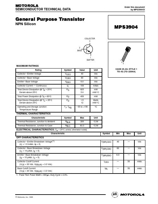
MOTOROLA
SEMICONDUCTOR TECHNICAL DATA
Order this document by MPS3904/D
General Purpose Transistor
NPN Silicon
COLLECTOR 3 2 BASE 1 EMITTER
10 < t1 < 500 µs DUTY CYCLE = 2%
*Total shunt capacitance of test jig and connectors
Figure 1. Turn–On Time
Figure 2. Turn–Off Time
2
Motorola Small–Signal Transistors, FETs and Diodes Device Data
500 k RS , SOURCE RESISTANCE (OHMS) RS , SOURCE RESISTANCE (OHMS) 200 k 100 k 50 k 20 k 10 k 5k 2k 1k 500 200 100 50 10 20 30 50 70 100 200 300 IC, COLLECTOR CURRENT (µA) 500 700 1k BANDWIDTH = 1.0 Hz 1M 500 k 200 k 100 k 50 k 20 k 10 k 5k 2k 1k 500 200 100 10 20 30 50 70 100 200 300 IC, COLLECTOR CURRENT (µA)
THERMAL CHARACTERISTICS
Characteristic Thermal Resistance, Junction to Ambient Thermal Resistance, Junction to Case Symbol RqJA RqJC Max 200 83.3 Unit °C/W °C/W
东奥轻一《初级会计实务》勘误
东奥轻松过关一《初级会计实务》勘误1、第一章资产P46 标题原文:第七节无形资产及其他资产更正为:第九节无形资产及其他资产2、第二章负债P134多选选择题#9答案原文:[答案]BC [解析]选项A……选项D中的增值税应在“应交税费——应交增值税”科目中核算。
更正为:[答案]ABC [解析]选项D中的增值税应在“应交税费——应交增值税”科目中核算。
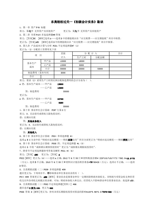
3、第九章产品成本计算与分析 P281不定项选择题#7(2)更正为:(2)分配的工资费用见下表原文:要求(2)采用生产工时的比例分配制造费用的会计分录为()。
A 借:基本生产成本——甲产品19800——乙产品 13200贷:制造费用 33000更正为:A 借:基本生产成本——甲产品24750——乙产品 8250贷:制造费用 330004、第十章事业单位会计基础 P297左第8行原文:3、无法偿付或债权人豁免偿还时:借:长期应付款贷;其他业务收入更正为:3、无法偿付或债权人豁免偿还时:借:长期应付款贷:其他收入5、第十章事业单位会计基础 P304 单项选择题 #4选项A B C分录中的“财政应返还额度——财政直接支付”科目全部更正为“财政应返还额度——财政授权支付”6、第十章事业单位会计基础 P305 四、不定项选择题 #1(3)选项C D 中的“或核销长期债券投资时”更正为“或核销长期股权投资时”。
7、跨章节不定项选择题参考答案及解析 P321 #4(6)原文:[答案] ABC更正为:[答案] AP322 [解析] 更正为:(6)……选项A正确;2012年6月30日W材料账面余额=(220+101+151+478)-862.5-12.5=75(万元),选项B不正确;2013年6月30日W材料应计提存跌价准备=75-50=25(万元),选项C不正确;……选项D错误。
8、全真模拟试题(二)P339 多项选择题 #39题目更正为:下列项目中,不影响事业单位事业结余的有()。
SP491中文资料,SP491E...

Now available in Lead Frees +5V Onlys Low Power BiCMOSs Driver/Receiver Enable (SP491E )s RS-485 and RS-422 Drivers/Receivers sPin Compatible with LTC490 and SN75179 (SP490E )s Pin Compatible with LTC491 and SN75180 (SP491E )s Improved ESD Specifications:±15kV Human Body Model±15kV IEC1000-4-2 Air Discharge ±8kV IEC1000-4-2 Contact DischargeDESCRIPTION…The SP490E is a low power differential line driver/receiver meeting RS-485 and RS-422standards up to 10Mbps. The SP491E is identical to the SP490E with the addition of driver and receiver tri-state enable lines. Both products feature ±200mV receiver input sensitivity,over wide common mode range. The SP490E is available in 8-pin plastic DIP and 8-pin NSOIC packages for operation over the commercial and industrial temperature ranges. The SP491E is available in 14-pin DIP and 14-pin NSOIC packages for operation over the commercial and industrial temperature ranges.ABSOLUTE MAXIMUM RATINGSThese are stress ratings only and functional operation of the device at these ratings or any other above those indicated in the operation sections of the specifications below is not implied. Exposure to absolute maximum rating conditions for extended periods of time may affect reliability.V CC ....................................................................................................+7V Input VoltagesDrivers................................................-0.5V to (V CC +0.5V)Receivers..................................................................±14VOutput VoltagesDrivers......................................................................±14V Receivers...........................................-0.5V to (V CC +0.5V)Storage Temperature....................................................-65˚C to +150˚Power Dissipation.....................................................................1000mWSPECIFICATIONSSPECIFICATIONS (continued)Figure 1. Driver DC Test Load Circuit Figure 2. Receiver Timing Test Load CircuitFigure 3. Driver/Receiver Timing Test Circuit Figure 4. Driver Timing Test Load #2 CircuitFigure 5. Driver Propagation DelaysFigure 6. Driver Enable and Disable TimesFigure 7. Receiver Propagation DelaysABSOLUTE MAXIMUM RATINGSThese are stress ratings only and functional operation of the device at these ratings or any other above those indicated in the operation sections of the specifications below is not implied. Exposure to absolute maximum rating conditions for extended periods of time may affect reliability.V CC ....................................................................................................+7V Input VoltagesLogic...................................................-0.5V to (V CC +0.5V)Drivers................................................-0.5V to (V CC +0.5V)Receivers..................................................................±14VOutput VoltagesLogic...................................................-0.5V to (V CC +0.5V)Drivers......................................................................±14V Receivers...........................................-0.5V to (V CC +0.5V)Storage Temperature......................................................-65˚C to +150Power Dissipation.....................................................................1000mWSPECIFICATIONSSPECIFICATIONS (continued)FEATURESThe SP490E and SP491E are full-duplex dif-ferential transceivers that meet the requirements of RS-485 and RS-422. Fabricated with a Sipex proprietary BiCMOS process, both products require a fraction of the power of older bipolar designs.THEORY OF OPERATIONThe RS-485 standard is ideal for multi-drop applications or for long-distance interfaces.RS-485 allows up to 32 drivers and 32 receivers to be connected to a data bus, making it an ideal choice for multi-drop applications. Since the cabling can be as long as 4,000 feet, RS-485transceivers are equipped with a wide (-7V to +12V) common mode range to accommodate ground potential differences. Because RS-485is a differential interface, data is virtually immune to noise in the transmission line.DriversThe drivers for both the SP490E and SP491E have differential outputs. The typical voltage output swing with no load will be 0 volts to +5volts. With worst case loading of 54Ω across the differential outputs, the driver can maintain greater than 1.5V voltage levels.The driver of the SP491E has a driver enable control line which is active high. A logic high on DE (pin 4) of the SP491E will enable the differ-ential driver outputs. A logic low on DE (pin 4)of the SP491E will tri-state the driver outputs.The SP490E does not have a driver enable.ReceiversThe receivers for both the SP490E and SP491E have differential inputs with an input sensitivity as low as ±200mV. Input impedance of the receivers is typically 15k Ω (12k Ω minimum).A wide common mode range of -7V to +12V allows for large ground potential differences between systems. The receivers for both the SP490E and SP491E are equipped with the fail-safe feature. Fail-safe guarantees that the receiver output will be in a high state when the input is left unconnected.The receiver of the SP491E has a receiverenable control line which is active low. A logic low on REB (pin 3) of the SP491E will enable the differential receiver. A logic high on REB (pin 3) of the SP491E will tri-state the receiver.ESD ToleranceThe SP490E/SP491E devices incorporate ruggedized ESD cells on all driver output and receiver input pins. The ESD structure is improved over our previous family for more rugged applications and environments sensitive to electro-static discharges and associated transients. The improved ESD tolerance is at least ±15kV without damage nor latch-up.There are different methods of ESD testingapplied:a) MIL-STD-883, Method 3015.7b) IEC1000-4-2 Air-Discharge c) IEC1000-4-2 Direct Contact The Human Body Model has been the generally accepted ESD testing method for semiconductors.This method is also specified in MIL-STD-883,Method 3015.7 for ESD testing. The premise of this ESD test is to simulate the human body’s potential to store electro-static energy and discharge it to an integrated circuit. The simulation is performed by using a test model as shown in Figure 9. This method will test the IC’s capability to withstand an ESD transient during normal handling such as in manufacturing areas where the ICs tend to be handled frequently.The IEC-1000-4-2, formerly IEC801-2, is generally used for testing ESD on equipment and systems. For system manufacturers, they must guarantee a certain amount of ESD protection since the system itself is exposed to the outside environment and human presence. The premise with IEC1000-4-2 is that the system is required to withstand an amount of static electricity when ESD is applied to points and surfaces of theFigure 10. ESD Test Circuit for IEC1000-4-2Figure 11. ESD Test Waveform for IEC1000-4-2t=0nst=30ns0A15A30At ¥i ¥equipment that are accessible to personnel during normal usage. The transceiver IC receives most of the ESD current when the ESD source is applied to the connector pins. The test circuit for IEC1000-4-2 is shown on Figure 10. There are two methods within IEC1000-4-2, the Air Discharge method and the Contact Discharge method.With the Air Discharge Method, an ESD voltage is applied to the equipment under test (EUT)through air. This simulates an electrically chargedperson ready to connect a cable onto the rear of the system only to find an unpleasant zap just before the person touches the back panel. The high energy potential on the person discharges through an arcing path to the rear panel of the system before he or she even touches the system. This energy, whether discharged directly or through air, is predominantly a function of the discharge current rather than the discharge voltage. Variables with an air discharge such as approach speed of the object carrying the ESD potential to the system and humidity will tend to change the discharge current. For example, the rise time of the discharge current varies with the approach speed.The Contact Discharge Method applies the ESD current directly to the EUT. This method was devised to reduce the unpredictability of the ESD arc. The discharge current rise time is constant since the energy is directly transferred without the air-gap arc. In situations such as hand held systems, the ESD charge can be directly discharged to the equipment from a person already holding the equipment. The current is transferred on to the keypad or the serial port of the equipment directly and then travels through the PCB and finally to the IC.The circuit models in Figures 9 and 10 represent the typical ESD testing circuits used for all three methods. The C S is initially charged with the DC power supply when the first switch (SW1) is on. Now that the capacitor is charged, the second switch (SW2) is on while SW1 switches off. The voltage stored in the capacitor is then applied through R S, the current limiting resistor, onto the device under test (DUT). In ESD tests, the SW2 switch is pulsed so that the device under test receives a duration of voltage.For the Human Body Model, the current limiting resistor (RS) and the source capacitor (CS) are 1.5kΩ an 100pF, respectively. For IEC-1000-4-2, the current limiting resistor (RS) and the source capacitor (CS) are 330Ω an 150pF, respectively.The higher CSvalue and lower RSvalue in the IEC1000-4-2 model are more stringent than the Human Body Model. The larger storage capacitor injects a higher voltage to the test point when SW2 is switched on. The lower current limiting resistor increases the current charge onto the test point.Table 1. Transceiver ESD Tolerance LevelsNow available in Lead Free. To order add "-L' to the part number. Example: SP488A = normal, SP488A-L = Lead freeORDERING INFORMATIONModel Temperature Range Package SP490ECN.......................................................0˚C to +70˚C.....................................................8-Pin NSOIC SP490ECP........................................................0˚C to +70˚C...........................................................8-Pin DIP SP490EEN......................................................-40˚C to +85˚C ...................................................8-Pin NSOIC SP490EEP......................................................-40˚C to +85˚C .........................................................8-Pin DIP SP491ECN .......................................................0˚C to +70˚C...................................................14-Pin NSOIC SP491ECP........................................................0˚C to +70˚C.........................................................14-Pin DIP SP491EEN......................................................-40˚C to +85˚C .................................................14-Pin NSOIC SP491EEP......................................................-40˚C to +85˚C .......................................................14-Pin DIP。
3544中文资料
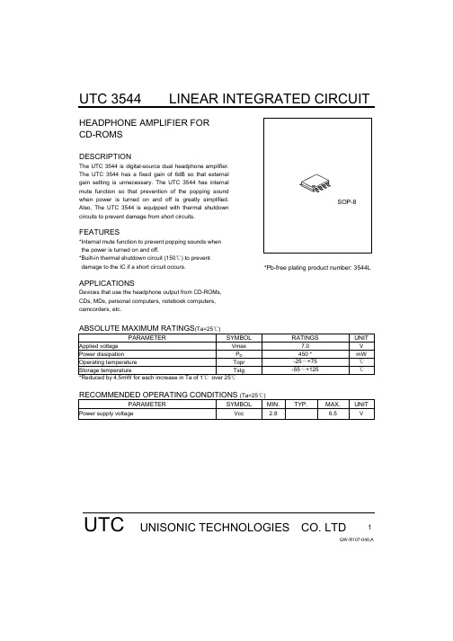
Devices that use the headphone output from CD-ROMs, CDs, MDs, personal computers, notebook computers, camcorders, etc.
SOP-8 *Pb-free plating product number: 3544L
ABSOLUTE MAXIMUM RATINGS(Ta=25℃)
PARAMETER
SYMBOL
Applied voltage
Vmax
Power dissipation
PD
Operating temperature
Topr
Storage temperature
Tstg
*Reduced by 4.5mW for each increase in Ta of 1℃ over 25℃
2
2
1
Po2
2
2
2
2
VNO
1
1
1
1
CS
1 1
1 2
2 1
1 1
1
RR
1
1
1
1
SW8A SW8B
2
OFF
2
ON
2
ON
2
ON
2
ON
2
ON
2
ON
2
ON
2
ON
1
ON
MONITOR IQ
CONDITIONS
V1AC,V2AC
V1AC,V2AC V1AC,V2AC V1AC,V2AC V1AC,V2AC V1AC,V2AC V1AC,V2AC
FMBT3904中文资料

FMBT3904中⽂资料Formosa MSIssued Date : 2002/12/25Revised Date :Page No. :1/3FMBT3904NPN EPITAXIAL PLANAR TRANSISTORDescriptionThe FMBT3904 is designed for general purpose switching amplifier applications.Absolute Maximum RatingsMaximum TemperaturesStorage Temperature.......................................................................................................-65~+150?C Junction Temperature................................................................................................................+150?C ?Maximu m Power DissipationTotal Power Dissipation (Ta=25?C).........................................................................................225 mW ?Maximum Voltages and Currents (Ta=25?C)VCBO Collector to Base Voltage....................................................................................................60 V VCEO Collector to Emitter Voltage................................................................................................40 V VEBO Emitter to Base Voltage .........................................................................................................6 V IC Collector Current....................................................................................................................200 mACharacteristics (Ta=25?C)Symbol Min.Typ.Max.Unit Test ConditionsBVCBO 60--V IC=10uA BVCEO 40--V IC=1mA BVEBO 6--VIC=10uAICEX --50nA VCE=30V, VBE=-3V *VCE(sat)1--200mV IC=10mA, IB=1mA *VCE(sat)2--300mV IC=50mA, IB=5mA*VBE(sat)1650-850mV IC=10mA, IB=1mA *VBE(sat)2--950mVIC=50mA, IB=5mA *hFE140--VCE=1V, IC=0.1mA *hFE270--VCE=1V, IC=1mA *hFE3100-300VCE=1V, IC=10mA *hFE460--VCE=1V, IC=50mA *hFE530--VCE=1V, IC=100mAfT 300--MHz VCE=20V, IC=10mA, f=100MHz Cob--4pFVCB=5V, f=1MHz*Pulse Test: Pulse Width ?380us, Duty Cycle ?2%Formosa MS Issued Date : 2002/12/25 Revised Date :Page No. :2/3Characteristics CurveFormosa MSIssued Date : 2002/12/25Revised Date :Page No. :3/3SOT-23 Dimension*:TypicalInches MillimetersInches Millimeters DIM Min.Max.Min.Max.DIM Min.Max.Min.Max.A 0.11020.1204 2.80 3.04J0.00340.00700.0850.177B 0.04720.0630 1.20 1.60K 0.01280.02660.320.67C 0.03350.05120.89 1.30L 0.03350.04530.851.15D 0.01180.01970.300.50S 0.08300.10832.10 2.75G 0.06690.0910 1.70 2.30V0.00980.02560.250.65H0.00050.00400.0130.10Notes:1.Dimension and tolerance based on our Spec. dated Sep. 07,1997.2.Controlling dimension: millimeters.3.Maximum lead thickness includes lead finish thickness, and minimum lead thickness is the minimum thickness of base material.4.If there is any question with packing specification or packing method, please contact your local HSMC sales office. Material:Lead: 42 Alloy; solderplatingMold Compound: Epoxy resin family, flammability solid burning class:UL94V-0Important Notice:All rights are reserved. Reproduction in whole or in part is prohibited without the prior written approval of HSMC. FORMOSA MS reserves the right to make changes to its products without notice.FORMOSA MS semiconductor products are not warranted to be suitable for use in Life-Support Applications, or systems. FORMOSA MS assumes no liability for any consequence of customer product design, infringement of patents, or application assistance.Head Office And Factory:Head Office & Factory (TAIPEI):4F.,No.21,Lane 126,Sec.3, Chung-Yang. Rd.Tu-Cheng,Taipei County,Taiwan R.O.C.Tel: 886-2-2269-6661Fax: 886-2-2269-6141。
3134中文资料
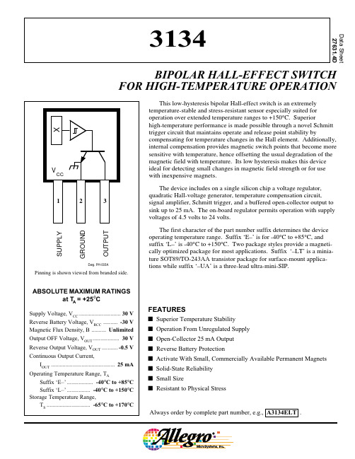
Always order by complete part number, e.g., A3134ELT .FEATURESs Superior Temperature Stability s Operation From Unregulated Supply s Open-Collector 25 mA Output s Reverse Battery Protections Activate With Small, Commercially Available Permanent Magnets s Solid-State Reliability s Small Sizes Resistant to Physical StressThis low-hysteresis bipolar Hall-effect switch is an extremely temperature-stable and stress-resistant sensor especially suited for operation over extended temperature ranges to +150°C. Superiorhigh-temperature performance is made possible through a novel Schmitt trigger circuit that maintains operate and release point stability bycompensating for temperature changes in the Hall element. Additionally,internal compensation provides magnetic switch points that become more sensitive with temperature, hence offsetting the usual degradation of the magnetic field with temperature. Its low hysteresis makes this device ideal for detecting small changes in magnetic field strength or for use with inexpensive magnets.The device includes on a single silicon chip a voltage regulator,quadratic Hall-voltage generator, temperature compensation circuit,signal amplifier, Schmitt trigger, and a buffered open-collector output to sink up to 25 mA. The on-board regulator permits operation with supply voltages of 4.5 volts to 24 volts.The first character of the part number suffix determines the device operating temperature range. Suffix ‘E–’ is for -40°C to +85°C, and suffix ‘L–’ is -40°C to +150°C. Two package styles provide a magneti-cally optimized package for most applications. Suffix ‘–LT’ is a minia-ture SOT89/TO-243AA transistor package for surface-mount applica-tions while suffix ‘–UA’ is a three-lead ultra-mini-SIP.Data Sheet 27631.4D3134BIPOLAR HALL-EFFECT SWITCHFOR HIGH-TEMPERATURE OPERATION3134LOW-HYSTERESISBIPOLAR HALL-EFFECT SWITCH FOR HIGH-TEMP. OPERATION115 Northeast Cutoff, Box 15036Worcester, Massachusetts 01615-0036 (508) 853-5000LimitsCharacteristic Symbol Test Conditions Min.Typ.Max.Units Supply VoltageV CC Operating4.5—24V Output Saturation Voltage V OUT(SAT)I OUT = 20 mA, B > B OP —175400mV Output Leakage Current I OFF V OUT = 24 V, B < B RP —0.05 1.0µA Supply Current I CC B < B RP (Output OFF)— 3.29.0mA B > B OP (Output ON)— 5.0—mA Output Rise Time t r R L = 820 Ω, C L = 20 pF —100—ns Output Fall Timet fR L = 820 Ω, C L = 20 pF—100—nsELECTRICAL CHARACTERISTICS over operating temperature range, at V CC = 12 V.MAGNETIC CHARACTERISTICS over oper. temp. and oper. supply voltage ranges.LimitsCharacteristic Symbol Test ConditionsMin.Typ.Max.UnitsOperate Point B OP -408.560G Release Point B RP -50-1950G HysteresisB hys5.02755GCopyright © 1995, 2003 Allegro MicroSystems, Inc.NOTES:B OP = operate point (output turns ON); B RP = release point (output turns OFF); B hys = hysteresis (B OP - B RP ).As used here, negative flux densities are defined as less than zero (algebraic convention).Typical values are at T A = +25°C and V CC = 12 V.1 gauss (G) is exactly equal to 0.1 millitesla (mT).3134LOW-HYSTERESISBIPOLAR HALL-EFFECT SWITCH FOR HIGH-TEMP . OPERATIONTYPICAL OPERATING CHARACTERISTICS025*******AMBIENT TEMPERATURE IN °C-50Dwg. GH-053125-25S U P P L Y C U R R E N T I N m A5.04.03.02.01.0150OUTPUT SATURATION VOLTAGESUPPLY CURRENT025*******AMBIENT TEMPERATURE IN °C-50Dwg. GH-052125-25S W I T C H P O I N T I N G A U S S150SWITCH POINTSHYSTERESIS025*******AMBIENT TEMPERATURE IN °C-50Dwg. GH-051125-25H Y S T E R E S I S I N G A U SS20101503040500255075100300AMBIENT TEMPERATURE IN °C200100-50Dwg. GH-029S A T U R A T I O N V O L T A G E I N m V-251253134LOW-HYSTERESISBIPOLAR HALL-EFFECT SWITCH FOR HIGH-TEMP. OPERATION115 Northeast Cutoff, Box 15036Worcester, Massachusetts 01615-0036 (508) 853-5000APPLICATIONS INFORMATIONExtensive applications information for Hall-effect sensors is available in:• Hall-Effect IC Applications Guide , Application Note 27701;• Hall-Effect Devices: Soldering, Gluing, Potting, Encapsulating, and Lead Forming , Application Note 27703.1;• Soldering of Through-Hole Hall-Sensor Dervices , Application Note 27703;and• Soldering of Surface-Mount Hall-Sensor Devices , Application Note 27703.2.All are provided in Allegro Electronic Data Book , AMS-702. or atOPERATIONThe output of these devices (pin 3) switches low when the magnetic field at the Hall sensor exceeds the operate point threshold (B OP ). At this point, the output voltage is V OUT(SAT). When the magnetic field is reduced to below the release point (B RP ) the device output goes high. Note especially that release can occur when the magnetic field is removed but to ensure release, a field reversal is required. The difference in the magnetic operate and release points is called the hysteresis (B hys ) of the device. This built-in hysteresis allows clean switching of the output even in the presence of external mechanical vibration and electrical noise.Powering up the device in the absence of a magnetic field (less than B OP and higher than B RP ) will allow in indeterminate output state. The correct state is warranted after the first excursion beyond B OP or B RP .Suffix “UA”SENSOR LOCATIONS(±0.005" [0.13 mm] die placement)Dwg. MH-011-4CSuffix “LT”Dwg. MH-008-4C0.0305"0.775 mm NOMThe products described herein are manufactured under one or more of the following U.S. patents: 5,045,920; 5,264,783; 5,442,283; 5,389,889; 5,581,179; 5,517,112;5,619,137; 5,621,319; 5,650,719; 5,686,894; 5,694,038; 5,729,130; 5,917,320; and other patents pending.Allegro MicroSystems, Inc. reserves the right to make, from time to time, suchdepartures from the detail specifications as may be required to permit improvements in the performance, reliability, or manufacturability of its products. Before placing an order, the user is cautioned to verify that the information being relied upon is current.Allegro products are not authorized for use as critical components in life-support appliances, devices, or systems without express written approval.The information included herein is believed to be accurate and reliable. However,Allegro MicroSystems, Inc. assumes no responsibility for its use; nor for any infringe-ments of patents or other rights of third parties that may result from its use.3134LOW-HYSTERESISBIPOLAR HALL-EFFECT SWITCH FOR HIGH-TEMP . OPERATIONPACKAGE DESIGNATOR ‘LT’(SOT89/TO-243AA)Dimensions in Inches (for reference only)Dimensions in Millimeters (controlling dimensions)NOTES: 1.Exact body and lead configuration at vendor’s option within limits shown.2.Supplied in bulk pack (500 pieces per bag) or add "TR" to part number for tape and reel.3.Only low-temperature (≤240°C) reflow-soldering techniques are recommended for SOT89 devices.0.440.35Dwg. MA-012-3 inPads 1, 2, 3, and B — Low-Stress VersionPads 1, 2, and 3 only — Lowest Stress, But Not Self AligningDwg. MA-012-3 mmPads 1, 2, 3, and B — Low-Stress VersionPads 1, 2, and 3 only — Lowest Stress, But Not Self Aligning3134LOW-HYSTERESISBIPOLAR HALL-EFFECT SWITCH FOR HIGH-TEMP. OPERATION115 Northeast Cutoff, Box 15036Worcester, Massachusetts 01615-0036 (508) 853-5000Dimensions in Inches (controlling dimensions)Dimensions in Millimeters(for reference only)PACKAGE DESIGNATOR ‘UA’NOTES: 1.Tolerances on package height and width representallowable mold offsets. Dimensions given are measured at the widest point (parting line).2.Exact body and lead configuration at vendor’s optionwithin limits shown.3.Height does not include mold gate flash.4.Recommended minimum PWB hole diameter to cleartransition area is 0.035" (0.89 mm).5.Where no tolerance is specified, dimension is nominal.6.Supplied in bulk pack (500 pieces per bag).Dwg. MH-014E in0.050BSC°Dwg. MH-014E mm1.27BSC°0.480.36Radial Lead Form (order A3240xUA-LC)NOTE:Lead-form dimensions are the nominals produced on theforming equipment. No dimensional tolerance is implied or guaranteed for bulk packaging (500 pieces per bag).0.100"(2.5 mm)Dwg. MH-026。
次氯酸钠溶液-化学品中文MSDS文档

化学品安全技术说明书修订日期: SDS编号:产品名称: 版本:次氯酸钠溶液第一部分化学品及企业标识化学品中文名:次氯酸钠溶液化学品英文名:sodium hypochlorite solution供应商名称:xxxxxxx化工有限公司供应商地址:xxxxxxx开发区供应商电话:0566-xxxxxxx邮编:xxxxxxx供应商传真:0566-xxxxxxx电子邮件地址:**************供应商应急咨询电话:0566-xxxxxxx化学事故应急咨询专线:0566-xxxxxxx产品推荐及限制用途:用于水的净化,以及作消毒剂、纸浆漂白等,医药工业中用制氯胺等。
第二部分危险性概述紧急情况概述:造成严重的皮肤灼伤和眼损伤。
GHS危险性类别:皮肤腐蚀/刺激-类别1B;严重眼损伤/眼刺激-类别1;危害水生环境-急性危害-类别1;危害水生环境-长期危害-类别1标签要素:象形图:警示词:危险危险信息:H314:造成严重的皮肤灼伤和眼损伤H410:对水生生物毒性极大并具有长期持续影响防范说明:预防措施:P260:不要吸入粉尘/烟/气体/烟雾/蒸气/喷雾。
P264:作业后彻底清洗……。
P280:戴防护面具。
P273:避免释放到环境中。
—如非其预定用途。
应急响应:P301+P330+P331:如误吞咽:漱口。
不要诱导呕吐。
P303+P361+P353:如皮肤(或头发)沾染:立即脱掉所有沾染的衣服。
用水清洗皮肤/淋浴。
P363:沾染的衣服清洗后方可重新使用。
P304+P340:如误吸入:将受害人转移到空气新鲜处,保持呼吸舒适的休息姿势。
P310:立即呼叫解毒中心/医生。
P321:具体治疗(见本标签上的.....)。
P305+P351+P338:如进入眼睛:用水小心冲洗几分钟。
如戴隐形眼镜并可方便地取出,取出隐形眼镜。
继续冲洗。
P391:收集溢出物。
安全储存:P405:存放处须加锁。
废弃处置:P501:处置内装物/容器……物理和化学危险:不燃,无特殊燃爆特性。
- 1、下载文档前请自行甄别文档内容的完整性,平台不提供额外的编辑、内容补充、找答案等附加服务。
- 2、"仅部分预览"的文档,不可在线预览部分如存在完整性等问题,可反馈申请退款(可完整预览的文档不适用该条件!)。
- 3、如文档侵犯您的权益,请联系客服反馈,我们会尽快为您处理(人工客服工作时间:9:00-18:30)。
I Configurable authentication and security settings to match customer system requirements
Compliance to existing MRTD (Machine Readable Travel Document) inspection equipment can be obtained by configuration settings according to ICAO document 9303. For driving licence applications, it can be configured to comply with ISO/IEC 18013-3, using BAP (Basic Access Protocol) security in configuration 1.
1.2 Smart eID family properties
Smart eID is designed to complement general-purpose smart card controllers in the NXP Semiconductors range of identification products for eGovernment applications. It is an “all-in” functionality product supporting ISO/IEC 7816 data structures, including those defined in ICAO document 9303. Smart eID is designed for low-end configurations in identification cards, driving licences or other eGovernment applications. The learning curve for implementers is quick, as the product is based on well-known standards. By using Smart eID, applications can be developed and validated within days. The Smart eID family can be regarded as low-end products due to their limited memory size. Triple-DES symmetric cryptography and the ISO/IEC 14443 type A contactless interface are supported.
P304_P308_P310G002_FAM_SDS_1
Product short data sheet
Rev. 01 — 29 July 2008
© NXP B.V. 2008. All rights reserved.
2 of 8
元器件交易网
NXP Semiconductors
NXP Semiconductors reserves the right to change aspects of manufacturing technology, including, but not limited to: silicon chip design, silicon die size, choice of silicon technology, silicon chip packaging. All aspects of the hardware platform relevant to NXP Semiconductors direct or indirect customers are documented in the full data sheet and other documents available for the Smart eID product family and its individual members.
The Smart eID family members feature a modular set of devices with:
• 4 KB to 10 KB EEPROM • Secured triple-DES coprocessor • ISO/IEC 14443 type A Contactless Interface Unit (CIU) • EEPROM with minimum 100 000 cycles endurance and minimum 20 years retention
I P310G002: N 4-byte unique identifier N With MIFARE 4 KB emulation
2.3 Security features
I Support for ICAO BAC and ISO/IEC 8013-3 in BAP configuration 1 I Self-securing file system I Data encryption on RF channel with replay attack protection I Hardware DES using 112-bit keys, featuring key version I Data authenticity by 8 bytes CMAC I Authentication on application level I Hardware exception sensors
The file system allows the creation of pre-configured applications that provide data groups within the application. Access to these data groups can be according to one of three modes: completely open (“LDS” – according to the Logical Data Structure defined in ICAO document 9303), protected with Basic Access Control and Secure Messaging (“BAC” – as defined in ICAO document 9303). A third configuration provides an additional mechanism to update data groups after issuing the electronic document to the holder as well as a feature to protect against cloning. These additional features make Smart eID particularly useful for ID cards, driving licences, and other eGovernment applications.
amount of non-volatile memory in KB, increasing count for further product options
zz
package type
1.4 Architecture overview
Every member of the Smart eID product family consists of hardware and software components. The overall deliverable is a module for integration into a contactless smart card or other contactless device. This module comes pre-configured with application software and is ready to be personalized by NXP Semiconductors direct or indirect customers.
time
• Pre-installed applications compliant to ICAO document 9303 • Command set compliant to ISO/IEC 7816-4 • Compliant to ISO/IEC 18013-3 (using BAP in configuration 1)
P304/P308/P310G002 family
Smart eID
2.2 Product-specific family features
I P304G002 and P308G002: N 7-byte unique identifier (cascade level two according to ISO/IEC 14443-3)
元器件交易网
NXP Semiconductors
P304/P308/P310G002 family
Smart eID
1.3 Naming convention
Table 1. Naming convention
P3xxG002zz Smart eID platform
xx
元器件交易网
P304/P308/P310G002 family
Smart eID
Rev. 01 — 29 July 2008
