CT646FY-1R5M中文资料
5M0365R中文资料

Features
• Precision Fixed Operating Frequency (100/67/50kHz) • Low Start-up Current(Typ. 100uA) • Pulse by Pulse Current Limiting • Over Current Protection • Over Voltage Protection (Min. 25V) • Internal Thermal Shutdown Function • Under Voltage Lockout • Internal High Voltage Sense FET • Auto-Restart Mode
Characteristic KA5M0365RN, KA5L0365RN Maximum Drain Voltage Drain-Gate Voltage (RGS=1MΩ) Gate-Source (GND) Voltage Drain Current Pulsed (1) Continuous Drain Current (Ta=25°C) Continuous Drain Current (Ta=100°C) Single Pulsed Avalanche Energy (2) Maximum Supply Voltage Analog Input Voltage Range
bias
Good logic
9V
5µA1mA2.5R R+OSC
− +
S Q
R
L.E.B
0.1V
7.5V −
+
Thermal S/D
27V − OVER VOLTAGE S/D
S Q
R
Power on reset
HPM 4 5 6 真空表说明书
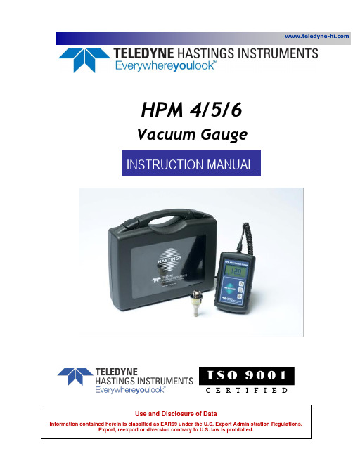
HPM 4/5/6Vacuum GaugeI S O 9001C E R T I F I E DManual Print HistoryThe print history shown below lists the printing dates of all revisions created for this manual. The revision level letter increases alphabetically as the manual undergoes subsequent updates. Each new revision includes a revised copy of this print history page.Revision A (Document Number 175-032014) ..................................................................... March 2014Revision B (Document Number 175-102014) ................................................................... October 2014Revision C (Document Number 175-102022) ................................................................... October 2022Visit for WEEE disposal guidance.Description of Symbols and Messages used in this manualWARNING: indicates a hazardous situation, which, if not avoided, could result in death orserious injury. Do not proceed beyond a WARNING notice until the indicated conditions arefully understood.CAUTION: indicates a hazardous situation, which if not avoided, could result in minor ormoderate injury. Do not proceed beyond a CAUTION notice until the indicated conditions arefully understood and met.NOTICE: calls attention to a procedure or practice that if not correctly performed or adheredto, could result in equipment damage, loss of data, or inaccurate data.NOTE: is used for tips and other digressions.Hastings Instruments reserves the right to change or modify the design of its equipment without anyobligation to provide notification of change or intent to change.Table of Contents1.GENERAL INFORMATION (5)F EATURES (5)S PECIFICATIONS (6)A CCESSORIES (7)1.3.1.Installation Accessories (7)1.3.2.Calibration Reference Tubes (7)1.3.3.Accessories Index (7)2.INSTALLATION (9)R ECEIVING I NSPECTION (9)C ABLE R EMOVAL/I NSTALLATION (9)2.2.1.Removal (9)2.2.2.Installation (9)B ATTERY I NSTALLATION/R EPLACEMENT (10)2.3.1.Battery Life Notes (10)3.VACUUM GAUGE OPERATION (11)F RONT P ANEL (11)3.1.1.Pressure Graph (11)3.1.2.Battery Level (11)3.1.3.Tube Type (12)3.1.4.Current Pressure (12)3.1.5.Pressure Units (12)3.1.6.Power/Enter Key (12)3.1.7.DV Select/UP Key (12)3.1.8.Units Select Down Key (12)E LECTRICAL C ONNECTOR (12)Q UICK S TART (13)U SER O PTIONS AND A DJUSTMENTS (13)3.4.1.Auto-Shutoff (13)3.4.2.Contrast Adjust (13)C ALIBRATION (14)3.5.1.Preparation (14)3.5.2.Enter Calibration Mode (14)3.5.3.Select Tube Type and Units (14)3.5.4.Adjustment (14)T HERMAL C OEFFICIENT (15)4.WARRANTY AND REPAIR (16)W ARRANTY R EPAIR P OLICY (16)R ETURN P OLICY (16)5.OUTLINE DRAWINGS (17)1. General InformationThis manual contains technical and general information relating to the installation, operation, and calibration of vacuum gauges and gauge tubes manufactured by Teledyne Hastings Instruments (THI).For best performance, THI vacuum gauges should be operated with the appropriate THI gauge tube. Attempting to use a THI vacuum gauge with anoth er manufacturer’s tube may result in damage to the gauge and/or tube.NOTICE: Contact with harsh solvents and chemicals to any plastic parts of the HPM 4/5/6Vacuum Gauge can damage the unit and may void the warranty.NOTICE: Instrument repair should only be performed by Teledyne Hastings service technicians.NOTICE: Disconnecting the gauge tube by pulling on the cable may result in damage to thedevice. Always disconnect by pulling directly on the octal connector.CAUTION: There are no operator serviceable parts or adjustments inside the product.CAUTION: If this equipment is used in a manner other than that specified, the protectionprovided by the equipment may be impaired.FeaturesThe HPM 4/5/6 is a battery-operated hand-held vacuum gauge that supports the Teledyne Hastings DV-4, DV-5 and DV-6 series vacuum gauge tubes. It is designed for portability and ease of use in applications where AC power is not readily available.Digital circuitry powers the vacuum gauge tube and converts its output for display. The lightweight unit operates with a standard 9-volt battery and can be configured to display in units of Torr, mbar, or Pascal.The device can be calibrated from the front panel using an in-system vacuum tube at known vacuum orout-of-system using a Hastings Reference Tube. Front panel buttons enable switching between DV-4, DV-5, and DV-6 tubes. These tubes are rugged, noble-metal sensors which are resistant to corrosion and can be ordered with a variety of system connections such as VCR®, KF-16, KF-25, Glass, MiniConflat™ and 1/8" NPT, etc.Gauge Tube Pressure RangeDV-4 0.2-20 TorrDV-5 0.1-100 mTorrDV-6 1-1000 mTorrSpecificationsWARNING: Do not operate instruments exceeding the specifications listed below. Failure toheed this warning could result in serious personal injury and/or damage to the equipment.HPM 4/5/6 Vacuum Gauge:Range DV-4 – 0.01 − 20 TorrDV-5 – 0.1 − 100 mTorrDV-6 – 1 − 1000 mTorrAccuracy (w/ calibrated tube) DV-4 (0.01−10 Torr), ± (20% of Reading + 0.02 Torr)DV-5 (0.1−100 mTorr), ± (15% of Reading + 0.1 mTorr)DV-6 (1−1000 mTorr), ± (15% of Reading + 1 mTorr)Accuracy (w/ calibrated reference tube) DV-4 (0.01−10 Torr), ± (20% of Reading + 0.04 Torr)DV-5 (0.1−100 mTorr), ± (15% of Reading + 0.2 mTorr)DV-6 (1−1000 mTorr), ± (15% of Reading + 3 mTorr) Operating Temperature Range With alkaline battery (standard) -18 to 55°CWith lithium battery (standard) -20 to 60°CExternally powered -20 to 70°CStorage Temperature (without battery) -20 to 70°CInput Voltage 5.5 - 9.5 VDC, (9V Battery)Battery Life (with included battery) > 30 hoursOutline Dimensions in inches (mm) 3.35” by 5.66” by 1.40” (85 by 144 by 36)Weight (Approx.) 0.7 lbs. (0.3 kg)Cables (Approx.)2-ft sensor cable includedPressure Units DV-4 – Torr, mbar, PascalDV-5 – mTorr, μbar, PascalDV-6 – mTorr, mbar, μbar, PascalCE Compliance See table belowCE Standard ComplianceTEST StandardEMC/EMI Family EN61326Radiated Emissions EN55011ESD IEC 61000-4-2Radiated Immunity IEC 61000-4-3See tube product bulletin for available tube connection configurations.NOTICE: Use of an underpowered or under-voltage supply could result in equipment damage.Accessories1.3.1. Installation AccessoriesTeledyne Hastings Instruments offers a complete line of system attachments that permit easymaintenance for contaminated operations. Gauge tubes are offered with various system fittings to match almost any system requirement. Additionally, Teledyne Hastings’ complete line of quick disconnect attachments allows customers to install these special fittings and easily replace sensors without vacuum sealant or Teflon® tape. For particularly dirty systems, Teledyne Hastings offers a particle dropout trap containing a series of nine separate baffles which prevent solid contaminants from having a direct path to the sensor’s thermocouple.1.3.2. Calibration Reference TubesReference Tubes employ the same metal thermopiles used in all THI Vacuum Gauge Tubes. The thermopile is sealed in a glass capsule that has been evacuated, baked, outgassed, and aged to ensure long-term stability. The sealed capsule is housed in a rugged metal shell to provide a trouble-free assembly.The reference gauge tube is calibrated to simulate a gauge tube at a given operating pressure (noted on the shell), and provides quick and easy adjustment.DAVC Compatible Reference TubesHastings # Model Name Hastings Tube Color Band55-101 DB-16D DV-4 Purple55-103 DB-18 DV-5 Red55-104 DB-20 DV-6 Yellow1.3.3. Accessories IndexVacuum Gauge TubesGauge Tubes – 20 Torr RangeStock # Model # Description55-19 DV-4D 1/8” MNPT Standard (Purple Base)55-19R DV-4R 1/8” MNPT Ruggedized55-258 DV-4D-KF-16 KF-16TM55-266 DV-4D-KF-25 KF-25TM55-227 DV-4D-VCR VCR TM55-69 DV-34 1/8” MNPT 316SS55-101 DB-16D Ref Tube (DV-4)Gauge Tubes – 100 mTorr RangeGauge Tubes – 1000 mTorr Range2. InstallationReceiving InspectionUnpack and inspect all items for obvious signs of damage. Immediately advise Teledyne Hastings andthe carrier of any suspected damage. In the unlikely event that items need to be returned, first obtain a Return Material Authorization (RMA) number from our Customer Service Department at 1-800-950-2468 (757-723-6531).Cable Removal/InstallationThe cable shipped with the HPM 4/5/6 (Part # CB-HPM 4/5/6) is attached to the instrument using a locking-type connector. This cable will need to be r emoved when replacing the instrument’s battery or when replacinga damaged cable. Refer to the following figures and instructions below:2.2.1. Removal1.Remove the instrument from the rubber boot (easier to reach the cable lock).a.Open the stand and push the bottom portion of the instrument out of the boot.b.Pull the rest of the instrument out of the boot.c.Be careful not to bend the cable connector plug.2.Pull the cable through the boot opening until you can easily grasp the Connector Plug.3.Twist the coupling ring counterclockwise about 120 degrees until you feel it unlock and hit the stop.4.Pull the connector plug out of the pin socket and boot opening.5.Leave off the cable assembly for maintenance or discard it if damaged.2.2.2. Installation1.Remove the rubber boot if not already off (see2.2.1)2.Thread the new cable through the boot opening and onto the pin socket3.Align the detent and push the connector plug until it bottoms out (all the way in).4.Push the coupling ring over the pin socket connection (you may need to twist the coupling ring slightlycounterclockwise to do this).5.Twist the coupling ring clockwise about 120 degrees until it locks.6.Push the instrument back into the boot.Battery Installation/ReplacementThe HPM 4/5/6 is shipped with a 9-volt alkaline PP3 battery (IEC # 6LR61, ANSI # 1604A). The battery compartment is on the back of the instrument inside the rubber boot.1.See2.2.1 to remove the instrument from the boot and disconnect the cable.2.Locate the battery compartment on the bottom rear of the case.3.Open the battery compartment by pressing in and sliding the compartment cover down4.Disconnect the old battery (if present)5.Plug in a new 9-volt battery and place battery and wires into the compartment.6.Reinstall the battery compartment cover by pressing down on the battery with the cover and slidingthe cover until it snaps into position7.See 2.2.2 to put the cable back on and re-insert into the boot2.3.1. Battery Life NotesBattery life specifications are given at 20°C. If the HPM 4/5/6 is operated for a significant time at temperatures much lower than this, battery life will be reduced. Alkaline batteries have an operating temperature range of -18°C − 55°C (0°F − 130°F). Lithium (not lithium ion) 9-volt batteries (ANSI # 1604L) are the recommended replacement when operating in cold or very warm temperatures. The operating temperature for Lithium batteries is -20°C − 60°C (-4°F − 140°F). Lithium batteries have better cold-weather behavior and longer battery life than alkali batteries at all temperatures.3. Vacuum Gauge OperationFront PanelThis section describes the primary operation of the user interface. See section 3.4 for operation in other modes.3.1.1. Pressure GraphThis shows a general indication of current pressure within the measurable range. If the pressure is higher than the measurable range, the graph flashes and displays an arrow on the right end. If the pressure is lower than the measurable range, the graph flashes and displays an arrow on the left end.3.1.2. Battery LevelDisplays battery life (charge). The battery should be changed when this indicator flashes.3.1.3. Tube TypeShows the type of gauge tube being measured. This is changed via the DV Select key.3.1.4. Current PressureDigital display of the current pressure. This flashes “999 Over Range” when pressure is higher than the measurable range. If lower than the measurable range, this flashes “000 Under Range”.NOTE: When ambient temperature is lower than calibration temperature, the display can shownegative numbers within limited ranges.3.1.5. Pressure UnitsShows the selected pressure units of the displayed pressure reading. This is changed via the Units Select key.3.1.6. Power/Enter Key•Turns the unit ON or OFF•When held during power on, displays the software version•When held longer than 3 seconds during power on, temporarily disables Auto-Shutoff•Acts as an Enter key in adjustment modes3.1.7. DV Select/UP KeyChanges the gauge tube type and functions as the up key in adjustment modes.3.1.8. Units Select Down KeyChanges the pressure units and functions as the down key in adjustment modes.Electrical ConnectorTeledyne Hastings vacuum gauge tubes interface with the HPM 4/5/6 via the included octal connector. The connector is “keyed” so that proper connection is assured (only fits the correct orientation). Always grip the connector by its cover and not the cable when plugging or unplugging. In some cases, corrosion may build up on the gauge tube pins. To ensure a good connection and accurate readings, use Scotch-Brite or an equivalent abrasive to clean the pins when needed.NOTICE:Disconnecting the gauge tube by pulling on the cable may result in damage to the octal socket and/or cable. Always disconnect by pulling on the octal connector directly.Quick StartThe HPM 4/5/6 is shipped from the factory fully calibrated, and will provide immediate and accurate vacuum measurements when used with good gauge tubes.Quick Start Instructions1.Connect the octal socket to a DV4, DV5 or DV6 gauge tube.2.Turn the HPM 4/5/6 on using the power button.3.Check that the tube type displayed in the upper right-handcorner of the display matches the attached tube type.*If not, press the “DV-4, DV-5, DV-6” button until it does*4.Check that the units displayed in the lower right-hand cornerof the display are set appropriately.*If not, press the “Torr, mbar, Pa” button until they are*5.Once the correct tube type and units have been selected, thedisplay will indicate one of the following:i. A pressure value within the measurable range of selected tube type.ii.Flashing “999 OVER RANGE” which indicates the vacuum gauge tube iseither outside the measurable range, or not connected.iii.Flashing “000 UNDER RANGE” which indicates the vacuum gauge tube is ata pressure less than the measurable range.6.Press the power button to turn the unit off. This will helpprolong battery life.*If tube type and/or conversion units have been changed, the instrument willuse these selections the next time it is turned on. *User Options and Adjustments3.4.1. Auto-ShutoffIn order to maximize battery life, the HPM 4/5/6 will automatically power down after about 5 minutes. To temporarily disable this behavior, hold the power button down at power up until “AUTO OFF DISABLED” is displayed.3.4.2. Contrast AdjustIf the LCD display is difficult to read, the user may adjust the contrast as follows:•With power off, press and hold the Units Select key.•While holding the units select key, press and hold the power key until “Adjusting Contrast” is displayed.•Release both keys.•Use the Tube Select key to increase contrast, and the Units Select key to decrease contrast.•Press the power button to save the contrast and return to normal operation.CalibrationThe HPM 4/5/6 is calibrated for all three tube types (DV-4, DV-5, and DV-6) at the factory. This ensures valid readings will be displayed for each tube type when delivered. The user may re-calibrate the HPM 4/5/6 if desired using either a reference tube or a vacuum gauge tube at a known vacuum using the instructions below.3.5.1. Preparation•Ensure the HPM 4/5/6 is turned off.•Plug in a DV-4, DV-5 or DV-6 Reference tube or plug into a tube at a known vacuum within the valid range of the tube (see 1.2 for tube ranges).3.5.2. Enter Calibration Mode•Push and hold “TUBE SELECT” and “UNITS SELECT” simultaneously.•While holding these buttons, press and hold the “Power” button.•When the LCD displays “CALIBRATION MODE”, release all three buttons.•The LCD will display “CAL MODE” at the top and will flash “Select Tube Type” while flashing the tube type in the upper right-hand corner.3.5.3. Select Tube Type and Units•Press “TUBE SELECT” or “UNITS SELECT” until the correct gauge tube is displayed.•Press “POWER” to accept the tube type selection.•The LCD will flash “Select Units” while flashing the Pressure Units in the lower right-hand corner •Press “TUBE SELECT” or “UNITS SELECT” un til the desired pressure units are displayed.•Press “POWER” to accept the unit selection.•The LCD will now display the current pressure in the selected units.3.5.4. Adjustment•The user may now adjust the displayed pressure value by pressing “TUBE SELECT” (Up) to increase or “UNITS SELECT” (Down) to decrease.•Use the buttons to match the displayed pressure to the known vacuum level.•While adjusting, a message may be displayed informing the user that they must wait before further adjustment is allowed.•Allow time for the reading to settle (DV-5 tubes take about 3 minutes).•When the desired pressure value has been reached, press the “POWER” button to set this selection and exit calibration mode.NOTE: The table in 1.3.2 specifies which Teledyne Hastings reference tube to be used in calibration.Thermal CoefficientThe HPM 4/5/6 generates an AC heating voltage using an internal transformer. This heating voltage is supplied to the vacuum tube to warm up the thermocouples in order to measure the pressure. As the ambient temperature increases or decreases the internal resistance of the copper winding in the transformer also changes. This resistance change will change the AC heating voltage that the vacuum tube receives and changes the pressure reading slightly.Increasing temperature will cause thepressure readings to increase anddecreasing temperature will causethe pressure readings to decrease.The chart to the right shows theamplified output from the gauge tubeas the ambient temperature changesfrom -25°C to 77°C. The instrumentsare initially adjusted at an ambienttemperature of approximately 22°C.The dominant effect is the change inthe zero-pressure output of the tube.This effect can be corrected byadjusting the low pressure reading atthe operating ambient temperature.The mid-range of the tube is highlyimmune to temperature changes. Amuch smaller change will occur in thehighest-pressure area, but since thecurve is quite flat through this region,a small change in output can cause asignificant change in the indicatedpressure reading.The specified rate of change does notinclude actual changes in pressurethat occur in a closed vacuum systemduring temperature excursions.The typical rate of change is as follows:DV-4 (1.25% of reading + 2.2 mTorr)/°CDV-5 (0.1% of reading + 0.08 mTorr)/°CDV-6 (-0.21% of reading + 0.2 mTorr)/°C4. Warranty and RepairWarranty Repair PolicySee the company website for warranty information at:/terms&conditions.htmReturn PolicySee the company website for return information at:/terms&conditions.htmAny product returned for either warranty or non-warranty repair must have been issued a Return Material Authorization (RMA) form.RMA Forms may be obtained from the Information section of the Hastings Instruments website: /inforeq.htmWARNING: Contaminated parts can be detrimental to health and environment. Ensureinstruments are free of hazardous contamination prior to shipment.Company contact informationTELEDYNE HASTINGS INSTRUMENTS804 NEWCOMBE AVENUEHAMPTON, VIRGINIA 23669 U.S.A.ATTENTION: REPAIR DEPARTMENTTELEPHONE (757) 723-65311-800-950-2468FAX (757) 723-3925E MAIL mailto:*****************************INTERNET ADDRESS 5. Outline DrawingsThe following section(s) show the outline dimensions for the HPM 4/5/6.。
MRF9045M中文资料
Z3 Z4 Z5 Z6 Z7 Z8 Z9 Z10 Z11 Z12 Z13
0.14″ x 0.32″ 0.47″ x 0.32″ 0.16″ x 0.32″ x 0.62″ Tapered 0.18″ x 0.62″ 0.56″ x 0.62″ 0.33″ x 0.32″ 0.14″ x 0.32″ 0.36″ x 0.08″ 1.01″ x 0.08″ 0.15″ x 0.08″ 0.29″ x 0.08″
N–Channel Enhancement–Mode Lateral MOSFET
MRF9045M MRF9045MR1
945 MHz, 45 W, 28 V LATERAL N–CHANNEL BROADBAND RF POWER MOSFET
CASE 1265–06, STYLE 1 (TO–270) PLASTIC
mrf9045m中文资料lm358中文资料12864中文资料lm393中文资料mpu6050中文资料lm324中文资料7805中文资料max232中文资料tl431中文资料op07中文资料74hc595中文资料
元器件交易网
MOTOROLA
SEMICONDUCTOR TECHNICAL DATA
MAXIMUM RATINGS
Rating Drain–Source Voltage Gate–Source Voltage Total Device Dissipation @ TC = 25°C Derate above 25°C Storage Temperature Range Operating Junction Temperature Symbol VDSS VGS PD Tstg TJ Value 65 + 15, – 0.5 156(1) 1.25(1) – 65 to +150 150 Unit Vdc Vdc Watts W/°C °C °C
美国AEMC公司高端和可移动数字弱电阻抗度计6550和6555产品说明书

Technical Assistance (800) 343-1391 110kV and 15kV DigitalMegohmmetersModels 6550 & 6555► Insulation measurementup to 30T Ω► Test voltages up to 15,000V► Step, ramp & fixed voltagetesting► Multiple test modes: voltageramp and step with “Burn-In”, “Early-Break” and “I-Limit” modes► 3 filter choices to optimize measurement stability► Selectable voltage from40V to 10,000 / 15,000V ► Storage of up to 80,000 measurements► Optically-isolated USBcommunication for data transfer to PC and report generation using DataView ® softwareExpert tools for testing insulation safely & accuratelyIP 54Our products are backed by over 130 years of experience in test and measurement equipment, and encompass the latest international standards for quality and safety.Technical Hotline: (800) 343-13912 Technical Assistance (800) 343-1391Models 6550 & 6555HIGH-END & PORTABLEThe Megohmmeter Models 6550 and 6555 are high-end portable instruments intended for measuring a wide variety of electrical insulation resistance values oncables and devices operating at high voltage. They are packaged in a rugged case that is IP54 rated (cover closed). Test results and configuration information is provided on a graphical LCD screen, as well as exportable throughthe use of the DataView ® software provided. TheMegohmmeters can operate on battery or AC power while testing.These Megohmmeters contribute to the safety ofelectrical installations and equipment. Their operation is managed by microprocessors that acquire, process, display and store the measurements.The Model 6550 makes insulation measurements at voltages up to 10,000 V , the Model 6555 up to 15,000 V .Main Functions:• Detection and measurement of input voltage, frequency, and current prior to running a test.• Quantitative and qualitative insulation measurements.• Measurements at a fixed test voltage of 500, 1000, 2500, 5000, 10,000 or 15,000 V dc .• Measurements at an adjustable test voltagebetween 40 and 15,000 V dc preselected by the user prior to the test. Three preselected test voltages can be stored in the instrument and can be modified as needed prior to starting a test.IP 54• Ramp voltage measurements with a ramp from 40 to 10,000 V or 15,000 V , model dependent. Three ramp profiles can be stored in the instrument. Each ramp profile includes the starting and ending test voltage and the ramp time between the two.• Step voltage measurements with steps from 40 to 10,000 V or 15,000 V , model dependent.Three step voltage profiles can be stored in the instrument. Each contains up to 10 steps that include test voltage and duration.• Three test current choices: Burn-In, Early-Break and I-Limit provide qualitative analysis tools for detection breaks in insulation.• Quality ratio calculations for DAR, PI, and DD are calculated and displayed.• Temperature correction of the measured resistance to a reference temperature.• Capacitance measurement of the device tested.• Residual current measurement.Model 6555 checking insulation resistance on feed cables to a three-phase motor.Technical Assistance (800) 3►► SELECTABLE VOLTAGE FROM 40V TO 10kV / 15kV MODELSINSULATION TESTSTest VoltageAPPLICATIONS► Acceptance testing and preventive maintenance ► Test motors, cables, switchgears and wiring installations4 Technical Assistance (800) 343-1391CONTROL FEATURESFront Panel Features for Models 6550 & 6555Socket for connection to the ACpower and recharging of thebuilt-in batteriesmeasurementbuttonsUSB connector forcommunicationto a PC Seven position access to the fixed voltage, adjustable voltage,ramp and stepLarge, digital, backlit, Models 6550 and 6555 have the same front panel with differences in the display only .5Measurement Results Display AreaDisplay ofResultsTechnical Assistance (800) 5FUNCTIONSModels 6550 & 65556 Technical Assistance (800) 343-1391bargraphterminalsExample of display during measurement.resistanceresistance referred to the reference temperature.cursor Resistance versus time graph.This curve is useful primarily in the case of a measurement in V-RAMP mode.When Timed Run (test with programmed duration) or Timed Run + DD is selected, the duration of the measurement (m:s) can be set.The number of measurements that can be recorded depends on the number of samples stored for each measurement.quality ofof memory white).indicated.T est with programmed durationExample of display before measurement.FUNCTIONAL DISPLAYSSOFTWARE & ANALYSIS SCREENSEasy identification of all stored test results.Real-time display of measurement results.Step voltage set up screen.Technical Assistance (800) 7ORDERING INFORMATION M egohmmeter Model 6550 Ramp, StepV , Variable, Auto DAR/PI/DD, USB w/DataView Megohmmeter Model 6555 Ramp, StepV , Variable, Auto DAR/PI/DD, USB w/DataView AEMC ® Instruments • 15 Faraday Dr. • Dover, NH 03820 USA • (800) 343-1391•Fax(603)742-2346•E-mail:**************Export Department: +1 (603) 749-6434 x520 • Fax +1(603)742-2346•E-mail:***************© Chauvin Arnoux ®, Inc. d.b.a. AEMC ®Instruments Call the AEMC ® Instruments Technical Assistance Hotline for immediate consultation with an applications engineer: (800) 343-1391950.BR-6550-6555_0323 • Printed in the USA M u lt i-p u r p o s e C la m p -O n M e t e r s ca o tl in M E G O H MM E T E R SFo r a ll of y ou r I ns ul at io n Te st in g ne ed s...ch ni ca l H o tl in e: (800) 343-1391.a em c.co mP O W E R Q U A L I T Y Fo rA ll Y ou r Po w er Q ua li ty N ee ds ...Te 43-1391w w w ( Fo r a ll of yo ur G ro un d In te gr ity T es tin g ne ed s...G R O U N D R E S IS TA N C E T E S TE R S Te ch ni ca l H ot lin e: (800) 343-1391w w w .a em c.co mTEST & MEA SUREM ENT INSTR UMEN TSVOLUM E 23WWW.AEM TECHNICA L HOTLINE : (800) 343-1391Family of ProductsTo learn more, visit 。
唯特利公司Victaulic无环扣温度计介面924型说明书
如需產品安裝、維護或支援資訊,請參考文檔末的資訊。
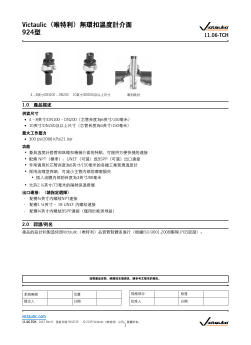
4 – 8英寸/DN100 – DN20010英寸/DN250及以上尺寸專利設計1.0 產品描述供貨尺寸• 4 – 8英寸/DN100 – DN200(芯管長度為6英寸/150毫米)• 10英寸/DN250及以上尺寸(芯管長度為6英寸/150毫米)最大工作壓力• 300 psi/2068 kPa/21 bar功能• 兼具溫度計套管和無環扣機械介面的特點,可提供方便快捷的連接• 配備 NPT (標準)、UNEF (可選)或BSPP (可選)出口連接 • 非常適用於芯管長度為6英寸/150毫米的各種工業玻璃溫度計• 採用流線型探頭,可減小主管內部的摩擦損失• 插入流體內部的長度為3英寸/80毫米• 允許2 ½英寸/73毫米的隔熱保溫套層出口連接:(請指定選擇) 配備¾英寸內螺紋NPT 連接配備1 ¼英寸– 18 UNEF 內螺紋連接配備¾英寸內螺紋BSPP 連接(僅用於歐洲地區)2.0 認證/列名產品的設計和製造依照Victaulic (唯特利)品質管制體系進行(根據ISO-9001:2008獲得LPCB 認證)。
Victaulic (唯特利)無環扣溫度計介面 924型11.06-TCH系統編號位置提交人日期規格部分段落批准人日期3.0 規格 – 材料本體和螺母:符合ASTM A536之65-45-12等級要求的球墨鑄鐵。
本體和螺母塗層:黑色醇酸樹脂瓷漆。
套環:ASTM A569熱軋、酸洗及油處理鋼,按照ASTM B633 FE/ZN 5, finish Type III進行電鍍鋅。
底座/襯墊:(請指定選擇1)“E”級EPDM(三元乙丙橡膠)EPDM(三元乙丙橡膠)(綠色條紋色碼)。
溫度範圍:–30°F至+230°F/–34°C至+110°C。
可用於指定溫度範圍內的熱水系統,以及多種稀酸、無油空氣和眾多化工應用場合。
威索和百得燃烧器配置表

德国威索燃气燃烧器配套清单1
德国威索燃油燃烧器配套清单2
德国威索油/气两用燃烧器配套清单3
德国“威索”
WG标配:主机、管理器(内含检漏程序)、电磁阀组(内含调压功能、过滤功能).说明书壹套.
WM-G标配:ABE操作面板、管理器W-FM50(内含检漏程序)、DMV双体电磁阀、WF气体过滤器、弯头、FRS稳压阀、说明书壹套. WM-GL标配:主机、管理器(内含检漏程序)、ABE操作面板、DMV双体电磁阀、WF气体过滤器、弯头、FRS稳压阀、油泵、油管、油
咀、说明书壹套
意大利百得燃气燃烧器配套清单4
意大利百得燃油燃烧器配套清单5
意大利百得油/气两用燃烧器配套清单6
意大利“百得” 气机标配:主机,电磁阀组。
油/气机标配:主机,电磁阀组,油泵、油管、油咀、说明书壹套。
M46L 型三相四线电力仪表使用说明(V2.7)说明书

1M46L型三相四线电力仪表使用说明(V2.7)一、概述●产品适用于三相交流电参数测量。
采用12位高速AD 芯片;●同时测量三相电流、电压,有、无功功率,频率、功率因数和电能;●具备电流、电压、功率、频率变送或上、下限报警,逆序报警功能;●输入输出采用互感器或光电隔离;●具备RS485/RS232网络通讯功能;二、主要技术指标●电压量程:0~450.0V (或定制其它≤4500V 量程),有效值;●电流量程:0.000~4500A/0~5A可自由设定。
有效值;●功率量程:0.000~9999kW 自动量程;●频率量程:10.0~100.0Hz ;●测量准确度:0.8%F.S ;●变送输出:4-20mA/F.S ;●报警输出:8A/220V 常开+常闭无源触点;●停电数据保存时间:100年;●工作环境:温度-20~+65℃湿度<85%●防护等级:IP00●工作电源:85~265VADC三、面板说明四、接线说明4.1端子定义RS232通信:18-TXD ;19-RXD ;20-GND RS485通信:19-A ;20-B注:功率变送4~20mA 对应0~V.FSH ×A.FSH ,三相则为之和,单位是kW ;五、操作方法5.1切换显示点按“SET”键,依次显示如下:A 相电流(A);频率(HZ);B 相电流(A);总有功功率(kW);C 相电流(A);总功率因数;A 相有功功率(kW )A 相无功功率B 相有功功率(kW )B 相无功功率C 相有功功率(kW )C 相无功功率A 相功率因数正有功电量EPB 相功率因数有功电量高四位C 相功率因数有功电量低四位继续点按“SET ”键:负有功电量-EP 负有功电量高四位负有功电量低四位正无功电量Eq 负无功电量Eq 无功电量高位负无功电量高位无功电量低位负无功电量低位电量计量范围:0.000~4000000.0kWh(或kvar.h),计满自动清零;手动清零方法:在电量显示画面下,按下“∨”键保持10秒钟清除电量值。
科瑞爱特 CT55500KVVA 系列三相工频电力专用 UPS 电源 使用手册说明书
科瑞爱特CreateU s e r M a n u a lC T50K V A系列三相工频电力专用U P S电源声明本资料著作权属科瑞爱特科技开发有限公司所有。
未经著作权人书面许可,任何单位或个人不得以任何方式摘录、复制或翻译。
侵权必究。
是科瑞爱特科技开发有限公司的注册商标。
科瑞爱特产品的名称和标志是科瑞爱特的专有标志或注册商标。
在未经科瑞爱特或第三方商标或商名所有者事先书面同意的情况下,本手册不以任何方式授予阅读者任何使用本手册上出现的任何标记的许可或权利。
本产品符合关于环境保护和人身安全方面的设计要求,产品的存放、使用和弃置应遵照产品手册、相关合同或相关国家法律、法规的要求进行。
由于产品和技术的不断更新、完善,本资料中的内容可能与实际产品不完全相符,敬请谅解。
如需查询产品的更新情况,请联系那个地办事处。
若需了解最新的资料信息,请访问网站:感谢您选择三相工频电力专用UPS电源!尊敬的用户:首先感谢您选用我们的产品,从现在开始我们将成为朋友!我们非常高兴向您提供这一系列电源产品,希望它在未来的岁月里为您提供方便、可靠的服务,保证您的设备安全运作。
为了您的安全和更好的使用该系列电源,请您在安装使用前务必仔细阅读此使用手册!如果您对本手册的内容有疑问或不明确之处,请您在使用逆变电源产品前与我们联系。
警告:不要拆卸电力U P S电源上的任何外壳或器件。
设备内部零件带有致命性的电压或存有高能量的危险!目录第一章 序言 (5)1.1 注意事项 (5)1.2 开箱检查 (6)1.3 储存环境 (6)1.4 搬运 (6)第二章 产品简介 (7)2.1 产品外观 (7)2.2 工作原理 (9)2.3 主要技术参数 (10)2.4 保护功能 (11)2.5 工作环境 (11)第三章 安装运行 (12)3.1 安装准备 (12)3.2 安装位置 (12)3.3 安装接线 (12)3.4 前面板操作和显示示意图及说明 (13)3.5 UPS电源试运行 (14)3.6 UPS电源的正常启动、关闭操作步骤 (15)第四章 显示异常信息和报警信号 (15)4.1 常见故障的原因及处理方法 (15)第五章 维护保养和售后服务 (16)5.1 维护保养 (16)5.2 售后服务 (16)第一章 序言三相工频电力专用UPS电源是为了电力保障,专为电力、通信系统设计,是一种将市电及电池的电能转化为净化的交流电能的变换装置,用以给计算机和其他电气设备提供可使用的连续交流电源,以备市电的不稳定及断电。
VFS6045型产品特性说明书

VFS6045SA102VFS6045SA151VFS6045SA451VFS6045VA031VFS6045VA102 VFS6045VA121VFS6045VA201VFS6045VA301E M C C o m p o n e n t sNoise suppression filterFor home appliances (conductive noise countermeasure) VFS seriesVFS6045 typeFEATURESAPPLICATIONPART NUMBER CONSTRUCTIONCHARACTERISTICS SPECIFICATION TABLEMeasurement equipmentEquivalent measurement equipment may be used.VFS6045V A031Series nameL×W×H dimensions V: at 10MHzS: at 1MHzInternal codeImpedance6.0×6.0×4.5 mm(Ω)Type Impedance DC resistance Rated current Part No.(Ω)Typ.(Ω)Min.(Ω)typ.(Ω)max.(A)max.6045VA[at 10MHz]57300.0120.0156 6.0VFS6045VA0311451200.0190.0247 5.1VFS6045VA1212422000.0230.0299 4.95VFS6045VA2014683000.0360.0468 3.6VFS6045VA301127510000.0750.0975 2.5VFS6045VA102 6045SA[at 1MHz]1881500.1750.2275 1.5VFS6045SA1515524500.470.6110.9VFS6045SA45112321000 1.15 1.4950.5VFS6045SA102Measurement item Product No.ManufacturerImpedance4294A Keysight T echnologiesDC resistance34420A Hewlett-PackardE M C C o m p o n e n t sVFS6045 typeZ FREQUENCY CHARACTERISTICSINSERTION LOSS VS. FREQUENCY CHARACTERISTICSE M C C o m p o n e n t s VFS6045 typeSHAPE & DIMENSIONSRECOMMENDED LAND PATTERNRECOMMENDED REFLOW PROFILEPACKAGING STYLETEMPERATURE RANGE, INDIVIDUAL WEIGHT *Operating temperature range includes self-temperature rise.**The storage temperature range is for after the assembly.Dimensions in mmDimensions in mmT ype A B KVFS6045 6.3 6.3 4.7Package quantity1500 pcs/reelOperating temperature range*Storagetemperature range**Individualweight–40 to +105 °C–40 to +105 °C0.6 gE M C C o m p o n e n t sREMINDERS FOR USING THESE PRODUCTSBefore using these products, be sure to request the delivery specifications.SAFETY REMINDERSPlease pay sufficient attention to the warnings for safe designing when using this products.The storage period is less than 12 months. Be sure to follow the storage conditions (temperature: 5 to 30°C, humidity: 10 to 75% RH or less).If the storage period elapses, the soldering of the terminal electrodes may deteriorate.Do not use or store in locations where there are conditions such as gas corrosion (salt, acid, alkali, etc.).Before soldering, be sure to preheat components.The preheating temperature should be set so that the temperature difference between the solder temperature and chip temperature does not exceed 150°C.Soldering corrections after mounting should be within the range of the conditions determined in the specifications.If overheated, a short circuit, performance deterioration, or lifespan shortening may occur.When embedding a printed circuit board where a chip is mounted to a set, be sure that residual stress is not given to the chip due to the overall distortion of the printed circuit board and partial distortion such as at screw tightening portions.Self heating (temperature increase) occurs when the power is turned ON, so the tolerance should be sufficient for the set thermal design.Carefully lay out the coil for the circuit board design of the non-magnetic shield type.A malfunction may occur due to magnetic interference.Use a wrist band to discharge static electricity in your body through the grounding wire.Do not expose the products to magnets or magnetic fields.Do not use for a purpose outside of the contents regulated in the delivery specifications.The products listed on this catalog are intended for use in general electronic equipment (AV equipment, telecommunications equip-ment, home appliances, amusement equipment, computer equipment, personal equipment, office equipment, measurement equip-ment, industrial robots) under a normal operation and use condition.The products are not designed or warranted to meet the requirements of the applications listed below, whose performance and/or qual-ity require a more stringent level of safety or reliability, or whose failure, malfunction or trouble could cause serious damage to society,person or property.If you intend to use the products in the applications listed below or if you have special requirements exceeding the range or conditions set forth in the each catalog, please contact us.(1) Aerospace/aviation equipment(2) T ransportation equipment (cars, electric trains, ships, etc.)(3) Medical equipment(4) Power-generation control equipment (5) Atomic energy-related equipment (6) Seabed equipment(7) T ransportation control equipment(8) Public information-processing equipment (9) Military equipment(10) Electric heating apparatus, burning equipment (11) Disaster prevention/crime prevention equipment(12) Safety equipment(13) Other applications that are not considered general-purposeapplicationsWhen designing your equipment even for general-purpose applications, you are kindly requested to take into consideration securing pro-tection circuit/device or providing backup circuits in your equipment.REMINDERSVFS6045SA102VFS6045SA151VFS6045SA451VFS6045VA031VFS6045VA102 VFS6045VA121VFS6045VA201VFS6045VA301。
2.1 RMS50 manual (中文)
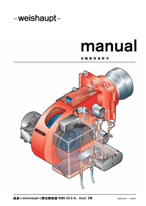
安装使用说明书威索(-weishaupt-)燃油燃烧器RMS 50/2-A,Ausf. ZM 830xxx01 - 1/200723目 录1 一般说明 52 安全须知 63 技术说明83.1 应用条件 83.2 基本功能 93.3 燃油调节系统 103.4 油泵12 3.4.1 独立泵站 12 3.4.2 一体式油泵 143.5 燃油预热系统153.6 燃烧控制管理器W-FM 的功能164 安装174.1 安装安全须知 174.2 运输及仓储 174.3 安装前的准备 174.4 供油系统 184.5 喷嘴的选择 214.6 燃烧器的安装 224.7 油管连接 244.8 电气线路连接255 调试及操作265.1 调试安全须知 265.2 首次调试前的措施 275.3 W-FM 的操作 285.4 调试及优化 295.5 调试后的措施 315.6 设备停止运行326 故障原因及排除336.1 燃烧器常见故障 336.2 W-FM 的故障3512345647 维护367.1 维护安全须知 367.2 维护工作367.2.1 测试、清洁和功能检查 367.3 混合装置的拆卸及安装 377.4 喷嘴的拆卸与安装 387.5 点火电极的设定 397.6 混合装置的设定和检查 407.7 混合装置伺服机构的拆卸和安装 417.8 风门伺服机构的拆卸和安装 427.9 回油调节器伺服机构的拆卸与安装438 技术数据448.1 燃烧器配置 448.2 工作范围表 448.3 适合的燃料 458.4 混合装置尺寸 458.5 允许的环境温度 468.6 电气数据 468.7 重量 468.8 燃烧器尺寸47附录48烟气分析 4878A1 一般说明本安装使用说明书 y 是设备的重要组成部分,必须始终保存于设备使用处备查;y部分内容在下列安装使用说明书中有所补充: - 燃烧控制管理器W-FM 使用说明书 - 燃油预热器使用说明书 y 只能由合格的专业人士进行指导;y 包含了有关设备安全的重要安装、调试及维护方面的说明;y对所有与设备运行有关人员均应引起注意。
唯特利公司产品说明书-无环扣温度计接口924型
如需产品安装、维护或支持信息,请参考文档末的信息。
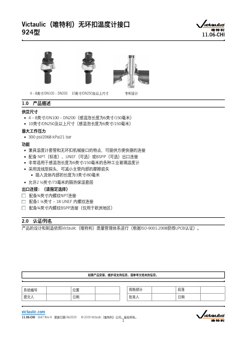
4 – 8英寸/DN100 – DN20010英寸/DN250及以上尺寸专利设计1.0 产品描述供货尺寸• 4 – 8英寸/DN100 – DN200(感温泡长度为6英寸/150毫米)• 10英寸/DN250及以上尺寸(感温泡长度为6英寸/150毫米)最大工作压力• 300 psi/2068 kPa/21 bar功能• 兼具温度计套管和无环扣机械接口的特点,可提供方便快捷的连接• 配备 NPT (标准)、UNEF (可选)或BSPP (可选)出口连接 • 非常适用于感温泡长度为6英寸/150毫米的各种工业玻璃温度计• 采用流线型探头,可减小主管内部的摩擦损失• 插入流体内部的长度为3英寸/80毫米• 允许2 ½英寸/73毫米的隔热保温套层出口连接:(请指定选择) 配备¾英寸内螺纹NPT 连接配备1 ¼英寸 – 18 UNEF 内螺纹连接配备¾英寸内螺纹BSPP 连接(仅用于欧洲地区)2.0 认证/列名产品的设计和制造依照Victaulic (唯特利)质量管理体系进行(根据ISO-9001:2008获得LPCB 认证)。
Victaulic (唯特利)无环扣温度计接口 924型11.06-CHI系统编号位置提交人日期规格部分段落批准人日期3.0 规格 – 材料本体和螺母:符合ASTM A536之65-45-12等级要求的球墨铸铁。
本体和螺母涂层:黑色醇酸树脂瓷漆。
套环:ASTM A569热轧、酸洗及油处理钢,按照ASTM B633 FE/ZN 5, finish Type III进行电镀锌。
底座/衬垫:(请指定选择1)“E”级EPDM(三元乙丙橡胶)EPDM(三元乙丙橡胶)(绿色条纹色码)。
温度范围:–30°F至+230°F/–34°C至+110°C。
可用于指定温度范围内的热水系统,以及多种稀酸、无油空气和众多化工应用场合。
C6-46系列排尘离心通风机
57.5
725
2634
59.5
715
3085
61
5C
1160
705 686
3536 3987
61 60.5
Y90L-2
2.2
657
4438
59
637
4989
57.5
598
5340
55
579
1960
57.5
579
2363
59.5
5C
1004
579 569 549
2366 3169 3572
61 61
Y90L-4
电动机
型号
功率(KW)
578
746
51.7
578
899
53.8
578
1052
54.9
3C
1830
568 558
1205 1358
54.9 54.4
Y90S-4
1.1
529
1511
53.1
510
1664
51.7
578
1817
49.5
2320
1735
2240
54.6
1754
2700
56.5
1735
3100
电动机
型号
功率(KW)
Y100L-2
2 (3)
Y100S1-4
2.2
Y132S-4
5.5
Y132M-4
7.5
Y132S-6
3
2
西安地址:西安市南二环东段 1 号东方广场 3 号楼 12304 室, , fansoft@
循 特 上海循特流体机械有限公司
(整理)YTC定位器中文版样本.

●智能阀门定位器●电- 气阀门定位器●气 - 气阀门定位器●空气过濾减压阀●气动放大器●气锁阀●气控换向阀●电磁阀●阀位变送器●限位开关目录Young Tech Co., Ltd. Rev.C0804公司历史 3认证书4,5产品目录智能阀门定位器 6 YT-2300系列(本安型)7YT-2350系列(不锈钢型)8YT-2301L(直行程远传型)9YT-2301R(角行程远传型)10 YT-2400系列(隔爆型)11 YT-2500系列(断信号保位型)电-气阀门定位器12 YT-1300系列(电子式)直行程 13 YT-1000L角行程14 YT-1000R(标准型)15 YT-1000R(圆顶指示器)16 YT-1000R + 阀位变送器(内置型)17 YT-1000R + 阀位变送器(外置型)18 YT-1000R + 限位开关(内置型)19 YT-1000R + 限位开关(外置型)20 YT-1000R + 阀位变送器+ 限位开关(内置型)21 YT-1000R + 阀位变送器+ 限位开关(外置型)气-气阀门定位器直行程22 YT-1200L角行程23 YT-1200R空气过濾减压阀24 YT-200, YT-205气动放大器25 YT-300,YT-305, YT-310, YT-315,YT-320气锁阀26 YT-400, YT-405气控换向阀27 YT-500,YT-505, YT-510, YT-515电磁阀28 YT-700阀位变送器29 PTM-5VL,R(本安型)30 PTM-6VL,R(隔爆型)31PTM-6VR + 限位开关(隔爆型)限位开关32 YT-85033 YT-860(隔爆型)支架,反馈杆 34351996.01 成立YoungTech co.,Ltd. 1996.05 生产电-气阀门定位器YT-1000L,R 1996.08 生产空气过濾减压阀YT-200 ,220 1997.07 生产气动放大器 YT-3001997.12 生产气-气阀门定位器YT-1200L,R 1998.02 生产阀位变送器 PTM-5L,R1998.08 电-气阀门定位器YT-1000L,R 获得CE 证书 1999.04 生产智能阀门定位器 YT-2000L,R 1999.06 生产气动放大器YT-3101999.10 电-气阀门定位器YT-1000L,R 获得EM 证书(韩国政府颁发) 2000.01 获得ISO 9001认证2000.04 获得风险投资企业认证 (韩国政府颁发) 2000.07 生产气锁阀YT-4002000.11 生产气控换向阀YT-500,510 2001.01 生产阀位变送器PTM-6L, R 2001.05 建新工厂2001.08 电-气阀门定位器YT-1000L,R 获得KEMA EExmdIIBT4防爆等级证书 2001.11 电磁阀YT-700,710,720 获得ExdIICT6防爆等级证书2002.02 OEM 生产日本本山(Motoyama )公司的EA91,EA90型电气阀门定位器 2002.05 加入HART 协会2002.07 获得出口有望中小型企业证书(韩国政府颁发) 2002.09 生产不锈钢型空气过滤减压阀YT-205 2003.02 升级为ISO 9001:20002003.10 电-气阀门定位器YT-1000L,R 获得ATEX EEx dm IIB T5防爆等级证书 2003.11 生产智能阀门定位器YT-2003系列 2004.01 设立研究所2004.01 生产阀位变送器PTM-5V,PTM-6V 系列 2004.11 生产智能阀门定位器YT-2400系列2005.01 电-气阀们定位器YT-1000系列获得CSA Ex md IIB T5防爆等级证书 2005.01 电-气阀们定位器YT-1000L 系列获得日本JIS IIB T5防爆等级证书 2005.01 生产电子式阀门定位器YT-1300系列2005.08 生产不锈钢智能阀门定位器YT-1350系列和电子式阀门定位器YT-1350系列 2005.09 获得韩国水利核电站供货资质。
英国CTUNIDRIVE-ES变频器参数说明

英国CTUNIDRIVE-ES变频器参数说明4201数冲脉器码编92.03s /m m 0001线曲S 车停52.03s /m m 0001线曲S 行运42.03s /m m 005线曲S 动启32.02s /m m 0051率斜速减车停22.0度速层多s /m m 00017V 12.0度速层双s /m m 00016V 02.0度速层单s/m m 0085V 91.0度速修检s /m m 0514V 81.0度速行爬s /m m 053V 71.02V 61.0速半修检s/m m 571V 51.0s /m m 0001度速定额梯电41.0m p r 0741速转定额机电31.0)择选单菜号0(0择选数参21.0)步同V E S (%002;)环闭L C (%571限流电60.0)入输量字数(r P 择选式模定给50.02s /m c 5.0率斜速减40.02s /m c 5.0率斜速加30.0m p r 0051度速高最20.00度速低最10.0;式模制控器频变改更3521;值厂出复恢3321;数参存保0001码密00.0:单菜号0#:明说数参器频变S E -E V I R D I N U T C 国英0.40自整定1(静态整定);2(旋转整定)0.41载波频率6KHZ0.42电机极数4按照电机铭牌设0.43同步电机相位角同步电机自整定得出0.44电机额定电压380V按照电机铭牌设0.45电机额定速度1470rpm按照电机铭牌设0.46电机额定电流25A按照电机铭牌设0.47电机额定频率50HZ按照电机铭牌设0.48控制模式CL.Vect(闭环);OPEN.Loop(开环);SerV o(同步) 必须在0.00中输入密码1253才能修改0.48参数#2号菜单2.02斜坡使能ON(1)2.03斜坡保持OFF(0)2.04斜坡方式选择FAST(1)2.10加速斜率选择器22.11加速斜率0.5cm/s2(等同于0.03)2.20减速斜率选择器22.21减速斜率0.5cm/s2(等同于0.04)#3号菜单3.24控制模式CL.Vect(闭环);OPEN.Loop(开环);SerV o(同步)(等同于0.48)3.34编码器脉冲数1024(等同于0.29)3.36编码器电压0(5V);1(8V);2(15V)3.38编码器类型0(Ab)差分编码器;9(SC.EndAt)海德汉1313编码器;3.41编码器自动检测ON(1)#4号菜单4.05运行电流限值2004.06再生电流限值2004.07对称电流限值2004.11转矩方式选择4(带力矩补偿的方式)4.12电流给定滤波器14ms(降低电机噪音)4.13电流环比例增益默认值4.14电流环积分增益默认值4.15热时间常数默认值#5号菜单5.06电机额定频率50HZ按照电机铭牌设(等同于0.47)5.07电机额定电流25A按照电机铭牌设(等同于0.46)5.08电机额定速度1470rpm按照电机铭牌设(等同于0.45) 5.09电机额定电压380V按照电机铭牌设(等同于0.44)5.10电机功率因数异步电机自整定得出5.11电机极数4按照电机铭牌设(等同于0.42)5.18载波频率6KHZ5.33千转马达电压根据铭牌计算出#8号菜单8.1031号端子取反选择0(不取反)1(取反)8.1124号端子取反选择1(取反)8.1225号端子取反选择08.1326号端子取反选择08.1427号端子取反选择08.1528号端子取反选择08.1629号端子取反选择08.1741,42号端子取反选择08.1822号端子取反选择18.2124号端子功能选择10.02变频器运行8.2225号端子输入源18.38多段速38.2326号端子输入源18.37多段速28.2427号端子输入源19.44正转(18.45=1可以改变正反转)8.2528号端子输入源18.44反转(18.45=1可以改变正反转)8.2629号端子输入源18.36多段速18.2741,42号端子功能选择10.01变频器正常(故障输出)8.2822号端子功能选择0.0024V电源输出8.29变频器端子功能选择1(0:0V输入有效;1:24V输入有效)8.3124号端子输入(出)选择1(0:输入;1:输出)8.3225号端子输入(出)选择0(0:输入;1:输出)8.3326号端子输入(出)选择0(0:输入;1:输出)#18号菜单18.11V175mm/s检修半速(等同于0.15)18.12V2(等同于0.16)18.13V350mm/s爬行速度(等同于0.17)18.14V4150mm/s检修速度(等同于0.18)18.15V5800mm/s单层速度(等同于0.19)18.16V61000mm/s双层速度(等同于0.20)18.17V71000mm/s多层速度(等同于0.21)18.18启动优化速度6mm/s(改善启动舒适感)18.23磁场建立阀值60018.25运行比例增益2000(高速P)18.26运行积分增益500(高速I)18.27启动比例增益30000(低速P)18.28启动积分增益1200(低速I)18.29电机额定转速1470rpm(等同于0.13)18.30电梯额定速度1000mm/s(等同于0.14)18.42多段速给定选择类型OFF(0)OFF(0):二进制ON (1):一对一给定18.45正转和反转方向取反OFF(0)ON(1)取反18.48切换增益选择ON(1)设为1,则分段有效,18.25-18.28起作用18.49惯量补偿ON(1)#19号菜单19.11增益转换时间2000ms19.13停车减速斜率1500mm/s2(等同于0.22)19.14启动S曲线500mm/s3(等同于0.23)19.15运行S曲线1000mm/s3(等同于0.24)19.16停车S曲线1000mm/s3(等同于0.25)19.17启动优化加加速度10mm/s3(从零速到启动优化速度的加速度) 19.25制动器打开延时500(制动器打开到速度命令给出的时间)19.26运行方向设置ON(1)双方向输入OFF(0单方向输入)19.27减速比的分母119.28启动优化时间1000ms19.29曳引轮直径400mm(根据现场轮子实际尺寸)19.30减速比分子119.34电流环滤波时间常数OFF(0)ON(1):4.12参数有效19.44顺时针方向(反转)OFF(0)#20号菜单20.01软件版本20.02软件运行标志20.10钢丝绳绕法21=1/1;2=2/1;二.电机自整定:1.电机处于空载状态;2.短接使输入,输出接触器和抱闸接触器吸合;3.设置参数#0.40=2;4.给变频器使能和方向信号;5.按键盘上的RUN键,曳引机会缓缓转动,变频器交替显示AUTO TUNE;6.当变频器显示STOP,去除使能和方向信号;7.#0.40自动归0;8.在#0.00菜单中输入1000,保存自整定参数;9.自整定参数保存在:异步电机:#5.10(功率因数);同步电机:#0.43(相位角);。
苏州艾源特便携式手持式超声波流量计(能量表)说明书

§ 2.1 如何开关机 .................................................................................................... 18 § 2.2 如何充电及判断内置电池电量 ........................................................................ 18 § 2.3 菜单结构及 LCD 液晶显示器 .......................................................................... 19 § 2.4 操作键盘 ....................................................................................................... 19
§ 4.5 查看测量数据 ................................................................................................. 42 § 4.6 测量数据处理 ................................................................................................. 43
§ 2.4.1 16 键键盘 ........................................................................................... 19 § 2.4.2 4 键键盘 ............................................................................................. 20
微差压开关
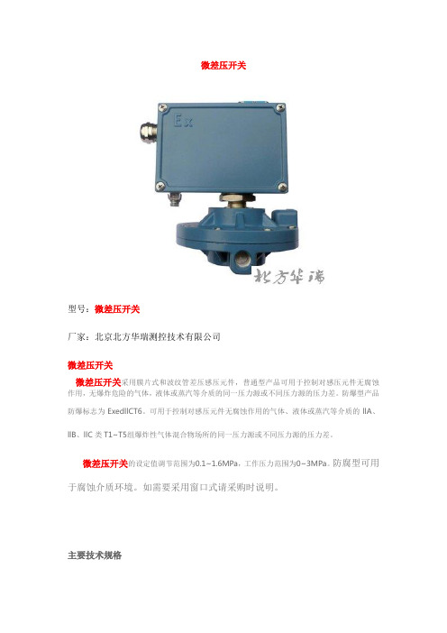
微差压开关
型号:微差压开关
厂家:北京北方华瑞测控技术有限公司
微差压开关
微差压开关采用膜片式和波纹管差压感压元件,普通型产品可用于控制对感压元件无腐蚀作用,无爆炸危险的气体,液体或蒸汽等介质的同一压力源或不同压力源的压力差。
防爆型产品
防爆标志为ExedllCT6。
可用于控制对感压元件无腐蚀作用的气体、液体或蒸汽等介质的llA、llB、llC类T1~T5组爆炸性气体混合物场所的同一压力源或不同压力源的压力差。
微差压开关的设定值调节范围为0.1~1.6MPa,工作压力范围为0~3MPa。
防腐型可用于腐蚀介质环境。
如需要采用窗口式请采购时说明。
主要技术规格
微差压开关
注:微差压开关参考资料来源北方华瑞官网:。
454FT流量计说明书

在数据输入过程中,如果输入错误,要修改的话,可以按 D 功能键,它只清除最后一位 的字符;按 C 功能键将清除当前的整个数值,数据清除后,需重新输入。一但设置的参数认 为是正确的,则可按 E 键进行确认。 6.帮助菜单
454FT 系列/504FT 系列 使用说明书
0
目录
第一部分 概述 ……………………………………… 第二部分 介绍 ……………………………………… 第三部分 基本操作 …………………………………… 第四部分 接线 ……………………………………… 第五部分 程序设置 …………………………………… 附件 1: 法兰连接安装示意图 附件 2: 带球阀安装示意图 附件 3: 24V DC 电源和 4~~20mA 信号输出接线示意图 附件 4: 220V AC 电源接线图 附件 5: 常见故障现象及判断方法
第三部、基本操作
这部分内容介绍仪表显示面板上各键的基本功能及操作。
左图为 454FT 可选配的键盘/LCD 示图
敲击膜片键,可进行程序设置及操作。
4
1.通电自检 LCD 显示面板可显示以下内容: a.通电时为亮绿背光显示。 b.显示屏幕上出现“Kurz Instruments Inc, Display Driver1.0”二秒钟。 c.二秒钟后出现“Kurz Insrtuments Inc.MFTV1.21” d.开始自动滚动显示,显示内容包括:时间、仪表位号、瞬时流量/累计流量、温度等。通 过键盘和 2×16LCD 显示器可以对 454FT 进行参数的设置。
454FTB系列100525中文版

应用场合
■ 工业气体的流量测量 ■ 美国EPA(环保局)颁布的大气污染法规中烟道气的流量测量 ■ 通风空气流量和化解过程中废气流量测量 ■ 溶剂回收系统流量测量 ■ 水泥厂生产过程中气体流量测量 ■ 压缩空气流量测量 ■ 半导体工艺气体测量 ■ 美国能源部空气取 样
■ 助燃气体流量测量 ■ 火炬气流量测量 ■ 焚烧炉烟气流量测量 ■ VOC烟道气流量测量 ■ 燃煤锅炉中助燃空气流量测量 ■ 天然气和大多数的工业气体流量测量 ■ 核电站 ■ O.E.M.应用
传感器材质:
标准配置: 哈氏合金C-276; 可选配: (1) 哈氏合金C-276材质传感器上涂氮化铬,更加耐磨损 (2) 在哈氏合金C-276传感器和传感器支撑杆上涂PTFE,耐腐蚀 但涂PTFE的HHT传感器:最高温度260℃
传感器支撑杆材质
316L 不锈钢, 可选配哈氏合金C-276;
重复性: 0.25% 流速响应时间:
气体标定
用户可选择实验室标定或相关气体标定。Kurz(S) 400D 型 NIST 可追踪风洞测量仪可用于空气标定。
传感器的保护
6
454FTB 的电路包括防止因传感器,电线或器件损坏而造成温度过高现象的保护电路。在零流量时,我们的传感器不会过热, 这与大部分竞争对手的设备不同,这是因为我们有与众不同的恒温传感器的控制方法和功率限制设计。
对于每种质量流量计型号pn编号和每种气体类型的基准流速v是指在标准状态下的最大流速方程式气体类型drp方程式drp10空气氮气氧气氩气1059drp12drp1353drp18drp30drp1000基本代码表使用定义说明方程式drppppsxtstp方程式在表2中所列的基准流速sfpm英制单位nmps公制单位vpht高温工作型号40hht超高温工作型号40fd2快速双铠装全焊接结构速度和温度传感器直径0105传感器探头ni无火花型atexcsa认证xpfp防爆隔爆型csa和atex认证ta一体型传感器和变送器于一体ts分体型传感器和变送器分别独立安装间距可调气体组号和气体类型气体组号气体类型氢气11vmax对于某种工艺条件下特定气体的最大流速流量因子ts标准绝对温度537r77f460英制单位
