USB转串口转换器CY-1150
USB串行转换器说明书
USB Serial Converter USB Serial Converter20116.0520Rev. 1.0.0.000Rev. 11Contents1.1.Introduction Introduction (2)1-1. Overview.............................................................................. 2 1-2. Package Contents................................................................ 2 1-3. System Requirements and Restrictions.............................. 2 1-4. DB9(RS-232C) connector Pin Assignment..........................32.I nstallation on nstallation on Windows PC Windows PC (4)2-1. Installation on Windows 10/8.1/8/7/VistaServer2012 R2/Server2012/Server2008 R2/Server2008........ 4 2-2. Confirmation........................................................................ 8 2-3. Uninstallation on Windows 10/8.1/8/7/VistaServer2012 R2/Server2012/Server2008 R2/Server2008 (9)3. . Sp Sp Specification ecification ecifications s (11)*All trademarks and logos are the properties of their respective holders. *The specifications and pictures are subject to change without notice.21.1.Introduction Introduction Introduction1-1.1. Overview Overview Overview● REX-USB60F is a USB to serial converter.Compatible with Universal Serial Bus specifications Rev. 1.1. ● Up to 230.4Kbps data transfer rate. ● Standard USB (A type Male) Easy to connect PC.●Virtual COM port driverREX-USB60F can be used with FTDI’s VCP drivers to provide a COM port on a PC.●LED indicatorsREX-USB60F has “PWR/TXD/RXD” LED indicators for monitoring communication status.PWR: power / TXD: transmit / RXD: receive1-2. Package C Package Contents ontents ontentsThis product is shipped with the following items: ● REX-USB60F USB Serial Converter ● Setup CD-ROM. ● Installation Guide● Warranty Card in Japanese1-3. System Requirements and Restrictions System Requirements and RestrictionsHost machine●Windows PC with free Standard USB A type portOperating System● Windows 10, Windows 8.1, Windows 8, Windows7, Windows Vista● Windows Server 2012 R2, Windows Server 2012, Windows Server 2008 R2, Windows Server 200831-4. DB9(DB9(RS RS RS--232C 232C)) connector connector Pin Assignment Pin Assignment Pin AssignmentThe pin assignment of the connector is below:This DB9pin connector is compatible with ANSI/EIA/TIA-574 specifications.Signal Name Name Direction Direction DTE DTE – DCE. DCE.Meaning Meaning1 DCD <--- Data Carrier Detected2 RXD <--- Received Data3 TXD ---> Transmitted Data4 DTR ---> Data Terminal Ready5 GND - Signal Ground6 DSR <--- Data Set Ready7 RTS ---> Request to Send8 CTS <--- Clear to Send 9RI<---Ring Indicator1 2 3 4 56 7 8 942. Installation Installation on on on Windows PC Windows PC Windows PCPlease make sure that the Windows PC meets the following specifications: • USB port is Standard-USB A • Windows version is Vista or later2-1.1. Installation Installation on Windows 10/8.1/8/7/Vista/on Windows 10/8.1/8/7/Vista/on Windows 10/8.1/8/7/Vista/Server 2012Server 2012 R2/Server2012R2/Server2012/Server 2008 R2/ Server 2008/Server 2008 R2/ Server 2008/Server 2008 R2/ Server 2008Before connecting the REX-USB60F USB serial converter to a USB port, follow the instructions below:1) Insert the setup CD-ROM for the REX-USB60F into your CD-ROM drive. Navigate to the [Setup] folder on the CD that contains the USB60F_Setup.exe Double click USB60F_Setup.exe.2) A “User Account Control” dialog box may appear. Click [Yes] to proceed with the installation.3) The InstallShield Wizard for RATOC REX-USB60F Installer will start. Click [Next] to proceed with the installation.4) A “RATOC REX-USB60F Installer“ will start.Click [Install] to proceed with the installation.55) A “Windows Security” dialog box will appear.Click [Install] to proceed with the installation.6) A “Windows Security” dialog box will appear again. Click [Install] to proceed with the installation.67) The screen will automatically complete and then change to the one below:Click [Finish]. The “RATOC REX-USB60F Installer” has finished. Connect the REX-USB60F to a spare USB port on your PC.The necessary drivers will be found.It will start installation and automatically finish.Proceed to (2-2) Confirmation of setting REX-USB60F to confirm the installation has finished properly.72-2.ConfirmationConfirmationFor confirming the installation has finished properly.Open the Device Manager and select “View > Devices by Connection”. Under the “Ports(COM/LPT)”category, the label “USB Serial Port” with an additional COM port will appear.If the label “USB Serial Port” shows without yellow “!” mark, the installation is done properly.892-3. Uninstallation on Wind Uninstallation on Windo o ws 10/8.1/8/7/Vista ws 10/8.1/8/7/Vista Server 2012Server 2012 R2/R2/Server 2012/S Server 2012/S Server 2012/Server 2008erver 2008erver 2008 R2/Server 2008R2/Server 2008Open the [Program and function] at the [Control Panel].Select the [RATOC REX-USB60F Installer] and click [Uninstall].The InstallShield Wizard for RATOC REX-USB60F Installer will start.The following dialog will appear. Click [Yes] to proceed with the uninstallation.The screen will automatically complete and then change to the one below:Click [Finish] to finish with the uninstallation.103. SpecificationSpecifications sProduct Name REX-USB60FSerial Input/Output level RS-232C levelUSB Specification USB(Universal Serial Bus) Specifications Rev. 1.1 Connector USB :Standard-USB Type A maleRS-232C:D-Sub9 male (with anchor [#4-40]) Number of I/O ports 1 portUnit Dimensions 3.35[L] x 1.1[W] x 0.43[H] in (85[L] x 28[W] x 11[H] mm) Cable Length Approx. 2.83 ft (85 cm)Weight 0.194 oz (55 g)Data transfer mode Asynchronous (Start stop synchronization)Data transfer Rate (Baud) 300/600/1,200/2,400/4,800/9,600/19,200/38,40057,600/115,200/230,400 bpsTransmit Distance Within 50ft (15m)Power Voltage DC+5V (Powered for USB Bus)Power Consumption Average: 36mA(5V) Max.: 60mA(5V)Serial Parameter Data bit: 7/8 Start bit:1 Stop bit: 1/2Parity bit: even/odd/noneRS-232C connector D-SUB9PIN RS-232C connector MaleANSI/EIA/TIA-574LED Indicators PWR:Power LEDIf 5V power from USB bus is properly suppliedfrom USB bus, this indicator LED will be on.TXD:Transmit data indicator (Host to Device)RXD:Receive data indicator (Device to Host) Operating Environment Temperature: 32ºF to 122ºF (0ºC to 50ºC)Humidity: 10 to 90% (non condensing)Storage Environment Temperature: -4ºF to 149ºF (-20ºC to 65ºC)Humidity: 10 to 90%(non condensing)Note:1.Do not remove while the application is communicating. System will beunstable.2.Do not operate to suspend while the application is communicating.System will be unable to resume properly.3.This product does not support the serial mouse for connecting to RS-232Cport.1112。
UPort_1110-1130-1150[1]
![UPort_1110-1130-1150[1]](https://img.taocdn.com/s3/m/99c9ac08b52acfc789ebc913.png)
机械特性
外壳: ABS + PC 重量: 产品净重: 65 g (0.14 lb) 含包装重: 200 g (0.44 lb) 尺寸: 38.4 x 60 x 20 mm (1.51 x 2.36 x 0.79 in)
串口
口数: 1 串口标准: UPort™ 1110: RS-232 UPort™ 1130: RS-422/485 UPort™ 1150: RS-232/422/485 接头: DB9针式
串口线保护
内建15 KV ESD保护:
性能
波特率: 50 bps ~ 921.6 Kbps
串口通讯参数:
数据位: 5, 6, 7, 8 停止位: 1, 1.5, 2 校验位: None, Even, Odd, Space, Mark 流控: RTS/CTS, XON/XOFF 主机分配 I/O地址: 主机分配 IRQ: 64 bytes FIFO:
6-12
订购信息
可选型号
1口RS-232 USB转换器 UPort™ 1110: 1口RS-422/485 USB转换器 UPort™ 1130: 1口RS-232/422/485 USB转换器 UPort™ 1150:
80 mm (3.150 in)
包装清单
• UPort™ 1110或1130或1150 USB转换器 • 1个迷你型转DB9端子接头 (仅UPort™ 1130/1150) • 文档和软件光盘 (打印版) • 快速安装指南 • 产品保修卡
38.4 mm (1.512 in)
UPort™ 1130/1150 接线端子适配器
此处列出的认证图标适用于部分或全部产品。 详情请参考Moxa网站上有 关认证的相关网页。
6
常用USB转串口芯片介绍
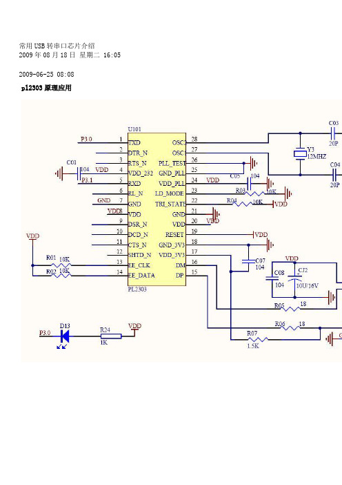
常用USB转串口芯片介绍2009年08月18日星期二 16:05 2009-06-25 08:08pl2303原理应用PL2303符合USB1.1标准,价格3RMB.2 CP2102/CP2103简介Silicon Laboratories公司推出的USB接口与RS232接口转换器CP2102/CP2103是一款高度集成的USB-UART桥接器,提供一个使用最小化元件和PCB空间来实现RS232转换USB的简便解决方案。
如图1所示,CP2102/CP2103包含了一个USB功能控制器、USB收发器、振荡器和带有全部调制解调器控制信号的异步串行数据总线(UART),采用5 mm×5 mm MLP-28的封装。
CP2102/CP2103作为USB/RS232双向转换器,一方面可以从丰机接收USB数据并将其转换为RS232信息流格式发送给外设;另一方面可从RS232外设接收数据转换为USB数据格式传送至主机,其中包括控制和握手信号。
2.1 USB功能控制器和收发器2.2 异步串行数据总线(UART)接口CP2102/CP2103 UART接口包括TX (发送)和RX(接收)数据信号以及RTS、CTS、DSR、DTR、DCD和RI控制信号。
UART支持RTS/CTS、DSR/DTR和X-On/X-Off握手。
通过编程设置UART,支持各种数据格式和波特率。
在PC机的COM端口编程设置UART的数据格式和波特率。
表1为其数据格式和波特率。
2.3 内部EEPROMCP2102/CP2103内部集成有1个EEPROM,用于存储由设备制造商定义的USB供应商ID、产品ID、产品说明、电源参数、器件版本号和器件序列号等信息。
USB配置数据的定义是可选的。
如果EEPROM没有被OEM的数据占用,则采用表1所示的默认配置数据。
注意,对于可能使用多个基于CP2102/CP2103连接到同一PC机的OEM应用来说,则需要专用的序列号。
Edgeport USB-到-串行转换器说明说明书
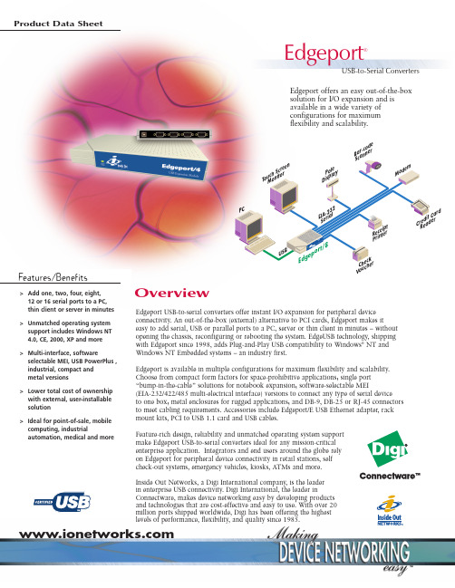
Edgeport USB-to-serial converters offer instant I/O expansion for peripheral device connectivity. An out-of-the-box (external) alternative to PCI cards, Edgeport makes iteasy to add serial, USB or parallel ports to a PC, server or thin client in minutes – without opening the chassis, reconfiguring or rebooting the system. EdgeUSB technology, shipping with Edgeport since 1998, adds Plug-and-Play USB compatibility to Windows ®NT and Windows NT Embedded systems – an industry first.Edgeport is available in multiple configurations for maximum flexibility and scalability.Choose from compact form factors for space-prohibitive applications; single port “bump-in-the-cable” solutions for notebook expansion; software-selectable MEI(EIA-232/422/485 multi-electrical interface) versions to connect any type of serial device to one box; metal enclosures for rugged applications; and DB-9, DB-25 or RJ-45 connectors to meet cabling requirements. Accessories include Edgeport/E USB Ethernet adapter, rack mount kits, PCI to USB 1.1 card and USB cables.Feature-rich design, reliability and unmatched operating system support make Edgeport USB-to-serial converters ideal for any mission-critical enterprise application. Integrators and end users around the globe rely on Edgeport for peripheral device connectivity in retail stations, self check-out systems, emergency vehicles, kiosks, ATMs and more.Inside Out Networks, a Digi International company, is the leader in enterprise USB connectivity. Digi International, the leader inConnectware, makes device networking easy by developing products and technologies that are cost-effective and easy to use. With over 20 million ports shipped worldwide, Digi has been offering the highest levels of performance, flexibility, and quality since 1985.Product Data SheetOverviewEdgeport offers an easy out-of-the-box solution for I/O expansion and is available in a wide variety of configurations for maximum flexibility and scalability.Features/Benefits12 or 16 serial ports to a PC, thin client or server in minutes >Unmatched operating system support includes Windows NT 4.0, CE, 2000, XP and more >Multi-interface, softwareselectable MEI, USB PowerPlus , industrial, compact and metal versions >Lower total cost of ownership with external, user-installable solution >Ideal for point-of-sale, mobile computing, industrialautomation, medical and moreC V ou c h a r de rB a r -c o d e n e r Edgeport®USB-to-Serial Converters•USB 1.0 and 1.1 compatible;backwards compatibility for 2.0•USB-IF certified•Plug-and-Play•Baud rate:to 230Kbps per serialport simultaneously•Automatic port reacquisition•COM port assignmentsmaintained across reboots•Full hardware and softwareflow control•Tri-state LED displays devicestatus and COM port activity•No additional IRQ or memoryaddress requirements•Low power consumption•Rack mountable•Hot-swappable•One-meter USB cable included(unless otherwise specified)•Bulk packaging and customizedcabling options•Multiple versions available formaximum flexibility andscalabilityEdgeport Serial•One,two,four,eight,12 or16 EIA-232 serial ports•DB-9,DB-25,RJ-45 connectors•Versions with onboard USB hub(four ports)Edgeport Compact•Two versions with DB-9connectors-Two EIA-232 serial ports-Two EIA-232 serial,twoUSB ports•Captive two-meter cable forsecure connection in ruggedenvironments like mobilecomputing•Smaller form factor and lowercost per port than standardEdgeportEdgeport Industrial•One,two,four or eight serialports with DB-9 connectors•EIA-232,-422 and -422/485•Software selectableEIA-232/422/485 MEIEdgeport Metal•Two or four serial ports withDB-9 connectors•Aluminum chassis•Designed for rugged environmentslike emergency vehicles andrestaurant kitchens•Rack mount brackets for addedsecurityEdgeport Multi-Interface•Two versions with DB-9 connectors-Two EIA-232 serial;1 parallelprinter port-Four USB,two EIA-232 serial,1parallel printer port•Ideal for workstations orthin clientsEdgeport USB Plus•Four powered USB,two EIA-232serial ports with DB-9 connectors•Connect standard USB,poweredUSB and legacy serial devices toone box•Cable locking mechanisms ensuresecure connection forperipheral devices•Part of Digi’s USB Plus Series(visit Web site for moreinformation)Edgeport/E USB EthernetAdapter•USB to RJ-45•Add a PC or laptop to a 10/100Base-T Ethernet in minutes•Data transfer rates up to 10Mpbs•Bus-poweredF E A T U R E SFeatures/Specifications• Ambient temperature:32º F to 131º F (0º C to 55º C)• Relative humidity:0% to 95% (non-condensing)E N V I R O N M E N T A L•FCC Part 15,Class B•CE•EN55022•EN55024•EN60950•UL 1950•CSA 2.2 No.950•IEC-950R E G U L A T O R YA P P R O V A L S•External power supply notrequired for versions without USBports (USB-powered)•Versions with USB ports(Edgeport/421,416,412,42+)ship with plug-mounted powersupply:120/230VAC 60/50Hz at5Vdc @3Amps maxP O W E RR E Q U I R E M E N T S•Windows®XP,Windows XP Embedded•Windows NT®4.0,Windows NT Embedded•Windows CE•Windows 2000•Windows Me•Windows 98/SE•Windows 95•Windows Server™2003•Linux•Sun Solaris (SPARC)O P E R A T I N G S Y S T E M Sd ge por t/Ve r aR uNDimensionsEdgeport/E, 1, 1i,•Length: 3.15 in (8.0 cm)•Width: 1.75 in (4.4cm)•Height:0.80 in (2.03 cm)•Weight: 1.6 oz (45.36 g)Edgeport/2c, 22c•Length: 2.38 in (6.04 cm)•Width: 4.94 in (12.55cm)•Height: 1.0 in (2.54 cm)•Weight: 5.0 oz (141.75 g)Edgeport/2, 2i, 2+2i, 21,4, 4i, 4s MEI, 421, 8r•Length:4.35 in (11.05 cm)•Width:7.2 in (18.29cm)•Height: 1.03 in (2.61 cm)•Weight:10.0 oz (311.0 g)Edgeport/4/DB-25, 42+, 8, 8i•Length:4.35 in (11.05 cm)•Width:7.2 in (18.29cm)•Height: 1.75 in (4.45 cm)•Weight:16.0 oz (453.59 g)Edgeport/2m, 4m•Length: 4.35 in (11.05cm)•Width:7.2 in (18.29cm)•Height: 1.03 in (2.61 cm)•Weight:10.0 oz (311.0 g)Edgeport/412, 412/DB-25,416, 416/DB-25, 8/DB-25•Length: 5.0* in (12.7cm)•Width:17.0** in (43.118cm)•Height: 1.8 in (4.53 cm)•Weight:41.3 oz (1170.84 g)*8.63 in (21.92 cm) with optionalmounted power supply tray** 19.0 in (48.26 cm) withoptional rack mount earsr e di t Ca r dR ea de re c ei p tP r in t ero ne yD i sp en se re po si t or yApplications•Retail/Point-of-Sale•Mobile computing•Medical•Financial•Hospitality•Industrial AutomationModelNorth America International Edgeport Serial Edgeport/1 (1 serial DB-9)301-1001-11301-1001-11Edgeport/1 25-Unit Bulk Pack (25 ea.301-1001-11)301-1001-21301-1001-21 Edgeport/1 100-Bulk Pack (100 ea.301-1001-11)301-1001-22301-1001-22 Edgeport/1 Captive Cable (1 serial DB-9,attached 2m USB cable)301-1001-15301-1001-15Edgeport/2 (2 serial DB-9)301-1000-02301-1000-02Edgeport/4 (4 serial DB-9)301-1000-04301-1000-04Edgeport/4/DB-25 (4 serial DB-25)301-1016-01301-1016-01Edgeport/412 (4 USB,12 serial DB-9)301-1004-12301-2004-12Edgeport/412/DB-25 (4 USB,12 serial DB-25)301-1016-12301-2016-12Edgeport/416 (4 USB,16 serial DB-9)301-1000-10301-2000-10 Edgeport/416/DB-25 (4 USB,16 serial DB-9)301-1016-16301-2016-16Edgeport/8 (8 serial DB-9)301-1002-08301-1002-08Edgeport/8/DB-25 (8 serial DB-25)301-1016-08301-1016-08Edgeport/8r (8 serial RJ-45)301-1002-14301-1002-14Edgeport CompactEdgeport/2c (2 serial DB-9,captive 2m USB cable)301-1003-10301-1003-10Edgeport/22c (2 serial DB-9,2 USB,captive 2m USB cable)301-1003-30301-1003-30Edgeport IndustrialEdgeport/1i (1 EIA-422/485 serial DB-9)301-1001-31301-1001-31Edgeport/2i (2 EIA-422/485 serial DB-9)301-1000-12301-1000-12Edgeport/2+2i (2 EIA-232 serial,2 EIA-422 serial DB-9)301-1022-04301-1022-04Edgeport/4i (4 EIA-422 serial DB-9)301-1000-24301-1000-24Edgeport/8i (8 EIA-422 serial DB-9)301-1000-28301-1000-28 Edgeport/4s MEI (4 EIA-232/422/485 software selectable)301-1000-94301-1000-94Edgeport MetalEdgeport/2m (2 serial DB-9,metal chassis)301-1000-80301-1000-80Edgeport/4m (4 serial DB-9,metal chassis)301-1000-81301-1000-81Edgeport Multi-Interface Edgeport/21 (2 serial DB-9,1 parallel)301-1000-21301-1000-21Edgeport/421 (4 USB,2 serial DB-9,1 parallel)301-1004-21301-2004-21Edgeport USB PlusEdgeport/42+ (4 powered USB,2 serial DB-9)301-1001-42301-2001-42AccessoriesEdgeport/E (USB Ethernet adapter)301-1050-01301-1050-01USB 1.1 Upgrade Kit (PCI to USB 1.1 card)301-1101-01301-1101-011-Meter USB Cable (A to B USB cable,3.3 ft)301-9000-01301-9000-012-Meter USB Cable (A to B USB cable,6.6 ft)301-9000-07301-9000-073-Meter USB Cable (A to B USB cable,9.8 ft)301-9000-06301-9000-064-Meter USB Cable (A to B USB cable,13 ft)301-9000-10301-9000-105-Meter USB Cable (A to B USB cable,16.4 ft)301-9000-02301-9000-02USB Repeater/Extender Cable A to A extender,16.4 ft)301-9002-01301-9002-01USB to Parallel Printer Cable (1.8 m,6 ft)301-9006-01301-9006-01Rack Mount Kit (19”shelf)301-9001-01301-9001-01Small Shelf Mount Bracket (mounts Edgeport/4-sized boxes to wall or shelf)301-9003-01301-9003-01Large Shelf Mount Bracket (mounts Edgeport/8-sized boxes to wall or shelf)301-9004-01301-9004-01Serial ports are EIA-232 unless otherwise specified.Bulk packs include one copy of software and documentation with limited use reproduction license.M O D E L......................P A R T N U M B E R SFeatures/SpecificationsDigi Internationa l11001 Bren Road E.Minnetonka,MN 55343 USA PH:877-912-3444952-912-3444FX:952-912-4952Email:*************Digi Internationa l GmbH J oseph-von-Fraunhofer Str.23D-44227 Dortmund GermanyPH:+49-231-9747-0 FX:+49-231-9747-111www.digi.deDigi Internationa l (HK)LimitedSuite 1703-05,17/F.,K Wah Centre 191 Java RoadNorth Point,Hong Kong PH:+852-2833-1008FX:+Inside Out Networks7004 Bee Caves Road Building 3,Suite 200Austin,TX 78746 USA PH:512-306-0600FX:512-306-0694Email:*******************91001226A2/604© 2003-2004 Digi International, Inc.Digi, Digi International, the Digi logo, the Digi Connectware logo, Inside Out Networks, the Inside Out Networks logo, Edgeport, and Watchport are either trademarks or registered trademarks of Digi International, Inc. in the United States and other countries worldwide. Microsoft, Windows, and the Windows logo are trademarks, or registered trademarks of Microsoft Corporation in the United States and/or other countries. All other trademarks are the property of their respective owners.D I G I SE R V I C EA N DS U P P O R TYou can purchase with confidence knowing that Digi is here to support you with expert technical support and a strong five-year warranty.Connectware ™®。
CH341 USB 总线转接芯片中文手册说明书

USB总线转接芯片CH341中文手册版本:3C1、概述CH341是一个USB总线的转接芯片,通过USB总线提供异步串口、打印口、并口以及常用的2线和4线等同步串行接口。
在异步串口方式下,CH341提供串口发送使能、串口接收就绪等交互式的速率控制信号以及常用的MODEM联络信号,用于为计算机扩展异步串口,或者将普通的串口设备直接升级到USB总线。
在打印口方式下,CH341提供了兼容USB相关规范和Windows操作系统的标准USB打印口,用于将普通的并口打印机直接升级到USB总线。
在并口方式下,CH341提供了EPP方式或MEM方式的8位并行接口,用于在不需要单片机/DSP/MCU 的环境下,直接输入输出数据。
除此之外,CH341B/F/A芯片还支持一些常用的同步串行接口,例如2线接口(SCL线、SDA线)和4线接口(CS线、SCK/CLK线、MISO/SDI/DIN线、MOSI/SDO/DOUT线)等。
2、特点2.1. 概述●全速USB设备接口,兼容USB V2.0,外围元器件只需要电容。
●可选:通过外部的低成本串行EEPROM定义厂商ID、产品ID、序列号等。
●支持5V电源电压和3.3V电源电压。
●低成本,直接转换原串口外围设备、原并口打印机、原并口外围设备。
●提供SOP-28、SSOP-20、QFN28三种无铅封装,兼容RoHS。
●由于是通过USB转换的接口,所以只能做到应用层兼容,而无法绝对相同。
2.2. 异步串口●仿真标准串口,用于升级原串口外围设备,或者通过USB增加额外串口。
●计算机端Windows操作系统下的串口应用程序完全兼容,无需修改。
●硬件全双工串口,内置收发缓冲区,支持通讯波特率50bps~2Mbps。
●支持5、6、7或者8个数据位,支持奇校验、偶校验、空白、标志以及无校验。
●支持串口发送使能、串口接收就绪等传输速率控制信号和MODEM联络信号。
●通过外加电平转换器件,提供RS232、RS485、RS422等接口。
UPort_1150_1150I

UPort™ 1150/1150I
USB转1口RS-232/422/485串口适配器,带光电隔离保护
UPort™ 1150
UPort™ 1150I
› 兼容USB 2.0标准 › USB数据传输速率为12 Mbps › 软件可选RS-232,RS-422,4线RS-485和2线RS-485 › 驱动支持Windows,Winows CE 5.0和Linux › 内建15 KV ESD全信号保护 › 2 KV光电隔离保护(UPort™ 1150I) › 提供全Modem信号 › LED状态灯指示(UPort™ 1150I)
USB转串口适配器 UPort™ 1150/1150I
订购信息
可选产品 UPort™ 1150:USB转1口RS-232/422/485串口适配器 UPort™ 1150I:USB转1口RS-232/422/485串口适配器,带 光电隔离保护
3-6
包装清单 • UPort™ 1150或UPort™ 1150I • 1个Mini DB9孔式转端子排配件 • 尼龙材质USB线缆 • 文档和软件CD • 快速安装向导(打印版) • 产品保修卡
1150/1150I兼容新旧RS-232/422/485设备,尤其适合移动、 测量和零售行业的应用。
电源来添加串口,大大节省了安装的时间和费用。
右下角显示U Po r t™图标。将鼠标放到U Po r t™图标上稍候 片刻之后,系统会弹出相关串口的数量。当同一个系统安装 多个U Po r t™之后,系统会弹出的信息将显示所有串口的数 量。
3
USB转串口适配器 UPort™ 1150/1150I
即插即用
UPort™ 1150/1150I USB转串口适配器可以通过笔记本或 工作站的USB接口扩展1个RS-232/422/485串口。UPort™
USB转串口适配器USB2S用户手册(HW101SF130)
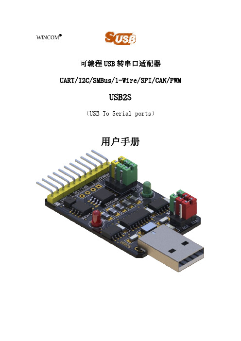
■串行接口转发器
■电子设备固件 ISP 升级
■EEPROM、FLASH 读写器、数据存储器
■串行接口芯片、设备测试、Demo 运行器
文档版本:V1.30
4 / 46
可编程串口转换适配器 USB2S 用户手册
目录
概述 ........................................................................................................................................................2 功能特点 ................................................................................................................................................2 一、结构组成 ........................................................................................................................................6
扩展功能
板载 IIC 接口 AT24CxxEEPROM 芯片、SHT 温湿度传感器芯片。 板载 SPI 接口 GD25Qxx 芯片,可用于 SPI 接口测试或者存储用户数据。 板载 1-Wire 接口 DS18B20 温度传感器/DS28EC20/2431/2502EEPROM 芯片 IIC 屏幕专用接口,连接 OLED12832 屏幕。
常见USB串口芯片
常用USB转串口芯片介绍2009-04-15 20:52:52| 分类:电路资料| 标签:|字号大中小订阅现在笔记本电脑更新速度很快,为了小型化的需求,原来在台式电脑上的标准配置接口例如串口、并口都被逐渐淘汰,取而代之的是USB这种通用小型的总线接口。
对于我们电子制作爱好者来说,为了编程、调试的需要,串口并口可还真少不了,特别是串口。
许多单片机调试时用串口来下载代码、输出调试信息、显示程序运行状态,缺少了串口的电脑,在调试时就显得十分不方便。
为此,厂商开发了专用的USB转串口的转换芯片,用于代替标准的串口,在一定程度上解决了笔记本电脑缺少串口的难题。
在此,笔者介绍三种比较常见的USB转串口芯片。
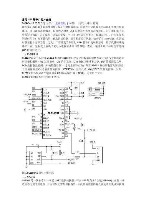
一、PL2303HXPL2303HX是一款符合USB1.1标准的USB接口异步串行数据总线转换器,包含六个标准调制解调器控制脚(RTS发送请求、CTS清除发送、DTR数据终端准备完毕、DSR数据准备完毕、DCD数据载波检测、RI响铃指示器);它的主要特点为:外置RS-232驱动器电源关闭控制;自动清除发送/发送请求的流控制(CTS/RTS);支持自动XON/XOFF软件流控制;另外,PL2303HX还集成两个综合用途I/O输入/输出脚(GRIO),方便用户使用。
PL2303HX的典型应用如图1所示。
图1 PL2303HX典型应用电路二、CP2102CP2102是一款单芯片USB转UART数据转换器,符合USB规范2.0全速(12Mbps),内置USB 收发器无需外部电阻、片内时钟无需外部振荡器,因此其最重要的特点就是单片集成转换器所需全部电路,可以在不使用任何分立元件情况下独立实现接口转换功能。
另外,它支持所有握手和调制解调器接口信号;支持硬件或X-On/X-Off握手;支持事件状态和线路中止条件。
CP2102典型应用电路如图2所示。
图2 CP2102典型应用电路*注,CP2102有一个引脚在芯片底下,就是图2所示引脚1上面的GND引脚三、FT8U232BMFT8U232BM也是一款单芯片USB转UART数据转换器,符合USB规范2.0全速(12Mbps),兼容1.1,内置USB收发器,配合片外6M晶振工作。
TOYOPUC PLC替换手册说明书
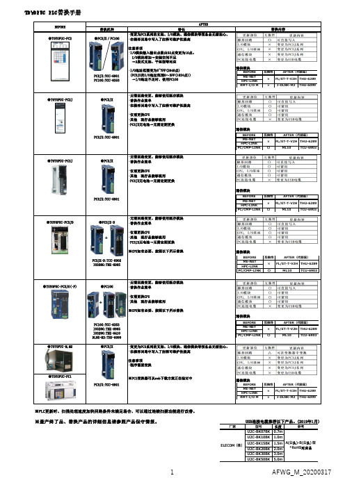
替换机种特长替换内容●TOYOPUC-PC2●PC3JX/PC10GPC3JX:TCC-6901PC10G:TCC-6353・变更为PC3系列的支架、I/O模块、通信模块等预备品无需担心。
・在梯形回路中写入了注释可维护性提高注意事项・I/O模块输入输出点数由32点变更为16点。
I/O模块增加→安装空间不足 →2段式支架、平坦型等对应・I/O地址范围变为0~7FF(2048点)(PC3JX的I/O地址范围0~3FF(1024点)) →I/O地址不足时、使用PC10G通信模块●TOYOPUC-PC2J ●PC3JXPC3JX:TCC-6901・无需回路变更、能够使用既存模块・替换作业简单・在梯形回路中写入了注释可维护性提高・仅需更换CPU・其他 现行品能够流用・PC3JX无电池→无需定期更换通信模块●TOYOPUC-PC3J ●PC3JXPC3JX:TCC-6901・无需回路变更、能够使用既存模块・替换作业简单・仅需更换CPU・其他 现行品能够流用・PC3JX无电池→无需定期更换通信模块●TOYOPUC-PC3JD ●PC3JX-DPC3JX-D:TCC-6902IO328G:THK-6905・无需回路变更、能够使用既存模块・替换作业简单・仅需更换CPU・其他 现行品能够流用・PC3JX无电池→无需定期更换※CPU如有必要、按照以下所示替换通信模块●TOYOPUC-PC3JG(-P)●PC10GPC10G:TCC-6353IO328G:THK-6905IO329G:THK-6410DLNK-M2:THU-6099・无需回路变更、能够使用既存模块・替换作业简单・仅需更换CPU・其他 现行品能够流用※CPU如有必要、按照以下所示替换通信模块●TOYOPUC-M,M2●TOYOPUC-PC1※量产终了品、替换产品的详细信息请参照产品保守情报。
USB连接电缆推荐以下产品。
(2019年1月)※PLC更新时、扫描处理速度加快回路条件未满足场合、可以通过连续扫描功能进行改善。
ICF-1150系列光纤转换器快速安装指南说明书

P/N: 1802011500017 *1802011500017*ICF-1150 Series Quick Installation GuideVersion 8.2, October 2022Technical Support Contact Information/support2022 Moxa Inc. All rights reserved.OverviewIntroductionThe ICF-1150 series of fiber converters has a multi-interface circuit that can handle RS-232 and RS-422/485 serial interfaces, as well as multi-mode or single-mode fiber. ICF-1150 series converters extend serial transmission distance up to 5 km (ICF-1150-M, with multi-mode fiber) or up to 40 km (ICF-1150-S, with single-mode fiber).Why Convert Serial to Fiber?Fiber communication not only extends the communication distance but also provides many helpful features.IMMUNITY FROM ELECTRICAL INTERFERENCE: Fiber is not affected by electromagnetic interference and radio frequency interference. It provides a clean communication path and is immune to cross-talk. INSULATION: Optical fiber is an insulator; the glass fiber eliminates the need for using electric currents as the communications medium. SECURITY: Fiber cannot be tapped by conventional electronic means and is very difficult to tap into optically. Furthermore, radio and satellite communication signals can be captured easily for decoding. RELIABILITY & MAINTENANCE: Fiber is immune to adverse temperature and moisture conditions, does not corrode or lose its signal, and is not affected by short circuits, power surges, or static electricity. Reverse Power ProtectionThe Reverse Power Protection feature provides extra protection against accidentally connecting the power cables to the wrong terminal. The converter detects automatically which power wire is positive and which is negative, and then adjusts the power supply accordingly.3-Way CommunicationThe ICF-1150 series supports 2 serial ports. The D-sub connector is for RS-232 communication and the removable terminal block is for RS-422 or RS-485 communication. The 3 ports (2 serial ports and one fiber port) are completely independent. When the ICF-1150 series converters receive data from any port, it will send data out through the other 2 ports. For example, when the ICF-1150 series converters receive a command from the remote Master via the fiber port, it will convert the command and transmit it via the RS-232 port and RS-422/485 port at the same time. So if the user is trying to monitor a system running on the RS-485 network, there is no need to use an additional RS-232 to RS-485 converter to connect the laptop computer’s serial port to the RS-485 bus.Rotary Switch for Setting the Pull Up/Down ResistorSince the RS-485 port can support multi-drop connections or daisy-chain connections, system engineers can connect meters, RTUs, readers, and many other devices together on the same bus. The impedance of the data line will rise according to the number of serial devices on the same bus. To get the system working, the ICF-1150 has a setting for tuning the pullup/down resistor. Just turn the dial to find the best resistor value for the system withoutremoving the ICF-1150 from the DIN rail. (The default settings are 1k for both switches.)Pull Up/Down ResistorPosition 0 1 2 3 45 6 7 89 Ohms 150k 10k 4.7k 3.3k1k909 822 770 500 485DIP Switch for Selectable TerminatorThe termination resistor for many products of this type is set by a jumper located inside the product’s casing. To disable or change the resistor’s strength, the user must open the casing to reset the jumper. Moxa offers a more user-friendly solution that allows users to set the termination resistor with a DIP switch located outside the ICF-1150 converter’s casing.No Configuration Required for Baudrate SettingsThe ICF-1150 works under any baudrate from 50 bps to 921.6 kbps. The ICF-1150 simply converts the signal back and forth between serial (RS-232, RS-422, or RS-485) and fiber. Since the ICF-1150 does not need to interpret the signal, it does not need to know the baudrate of the transmitting device.NOTE The ICF-1150I default setting is auto baudrate. If you need to use the fixed baudrate, then you will need to use the DIP switch to do the configuration.Ring ModeTo allow one half-duplex serial device to communicate with multiple half-duplex devices connected to a fiber ring, configure the ICF-1150 for “ring mode” by setting DIP switch “SW3” to the “On” position. The Tx port of a particular ICF-1150 unit connects to the neighboring converter’s Rx port to form the ring. Note that when one nodetransmits a signal, the signal travels around the ring until it returns tothe transmitting unit, which then blocks the signal. Users should ensure that the total fiber ring length is less than 100 km when using either single-mode models or multi-mode models.Features•“Ring” or “Point to Point” transmission•Extend RS-232/422/485 transmission distance:up to 40 km with single-mode—ICF-1150-S seriesup to 5 km with multi-mode—ICF-1150-M series•Supports baudrates up to 921.6 kbps•3-way galvanic isolation (for –I models)•Wide operating temperature from -40 to 85°C (for “T” models) •C1D2, ATEX, and IECEx certified for harsh industrial environments Package ChecklistBefore installing the ICF-1150, verify that the package contains the following items:•ICF-1150 fiber converter•Quick installation guide (printed)•Warranty cardNOTE Please notify your sales representative if any of the above items are missing or damaged.Mounting Dimensions (unit: mm)ICF-1150-SCICF-1150-STTop ViewFront ViewATTENTIONElectrostatic Discharge Warning!To protect the product from damage due to electrostaticdischarge, we recommend wearing a grounding device when handling your ICF-1150 product.Mounting (in an enclosure or industrial panel)The aluminum DIN rail attachment plate should be fixed to the back panel of the ICF-1150 when you take it out of the box. If you need to reattach the DIN rail attachment plate to the ICF-1150, make sure the stiff metal spring is situated towards the top, as shown in the figures below.STEP 1: Insert the top of the DIN rail into the slot just below the stiff metal spring. STEP 2: The DIN rail attachment unit will snap into place as shown below.To remove the ICF-1150 series from the DIN rail, simply reverse Steps 1 and 2 above.Pin AssignmentPinRS-2321 –2 TxD3 RxD4 –5 GND6 –7 –8 – 9–Pin RS-422 4-wire RS-485 2-wire RS-4851 GND GND GND2 Rx- Rx- Data -3 Rx + Rx + Data +4 Tx - Tx - –5 Tx + Tx +–Fiber CableSC-Port Pinouts SC-Port to SC-Port Cable WiringST-Port Pinouts ST-Port to ST-Port Cable WiringATEX and IECEx Information1.Certification number:DEMKO 10 ATEX 0917344XIECEx UL 13.0044X2.Ambient range:Model Ambient Temp. RangeModels without suffix“-T”0 to 60°CModels with suffix “T” -40 to 85°C3.Certification string: Ex ec IIC T4 Gc4.Standards covered: EN IEC 60079-0:2018, EN IEC 60079-7: 2015+A1:20185.IEC 60079-0, Edition 7, IEC 60079-7, Edition 5.1Conditions of safeusage:•The Ethernet communication devices must be mounted in a tool-accessible IP54 enclosure in accordance with IEC/EN60079-0 and used in an area of not more than pollutiondegree 2 as defined by IEC/EN 60664-1.•Provisions shall be made to prevent that transientdisturbances should exceed the rated voltage by over 140%.6.The Terminal blocks (J1, J2) are suitable for 14 to 28 AWG(3.31-0.08 mm2), with torque = 1.7 lb-in. The cross-sectional areaof the PE conductor is Sp=3.31 mm2. The conductor used forgrounding is 12 AWG minimum.7.Conductors suitable for use in an ambient temperature of 91°Cmust be used for the power supply terminal.Federal Communications Commission Statement FCC: This device complies with part 15 of the FCC Rules. Operation is subject to the following two conditions:1.This device may not cause harmful interference, and2.This device must accept any interference received, includinginterference that may cause undesired operation.Switch SettingsThere are 4 DIP switches on the front panel of the ICF-1150. Setting Switch 1 Switch 2RS-422 ON OFF2-wire RS-485 OFF ON4-wire RS-485 OFF (default) OFF (default)Fiber Mode Switch 3Ring Mode ONPoint to Point mode OFF (default)120Ω Terminator Switch 4Enable ONDisable OFF (default)The S3 DIP Switch is located inside the ICF-1150. When the ICF-1150 is in RS-485 mode, use this DIP switch to configure RS-485 data direction control, data format, and baudrate. When the ICF-1150 is in RS-232/422 mode, the S3 DIP switch cannot affect RS-232/422 communication.Direction Control and Data Format SettingYou will need to open the product's casing to do the Direction Control and Data Format Setting.NOTE Direction Control and Data Format Setting require the model version v1.2.0 or later.RS-485 Data Direction Control SettingsRS-485 Data Direction Control S3 Pin 1Auto Baudrate OFFFixed Baudrate ONData Format SettingsData Format S3 Pin 2 S3 Pin 3 S3 Pin 47 Bits OFF ON ON8 Bits ON OFF ON9 Bits OFF OFF ON10 Bits ON ON OFF11 Bits OFF ON OFF12 Bits ON OFF OFFThe serial data format includes one start bit, between five and eight data bits, and one stop bit. A parity bit and an additional stop bit might be included in the format as well.For example, 8-N-1 is interpreted as eight data bits, with no parity bit, and one stop bit. Users need to adjust the DIP switch to set the data format to 10 bits.Baudrate S3 Pin 5 S3 Pin 6 S3 Pin 7 S3 Pin 8 S3 Pin 9 50 OFF ON ON ON ON75 ON OFF ON ON ON110 OFF OFF ON ON ON 134.5 ON ON OFF ON ON150 OFF ON OFF ON ON300 ON OFF OFF ON ON600 OFF OFF OFF ON ON1200 ON ON ON OFF ON1800 OFF ON ON OFF ON2400 ON OFF ON OFF ON4800 OFF OFF ON OFF ON7200 ON ON OFF OFF ON9600 OFF ON OFF OFF ON 19200 ON OFF OFF OFF ON 38400 OFF OFF OFF OFF ON 57600 OFF ON ON ON OFF 115200 OFF ON ON ON OFF 230400 ON OFF ON ON OFF 460800 OFF OFF ON ON OFF 921600 ON ON OFF ON OFF LED IndicatorsThere are 3 LEDs on the front panel of the ICF-1150.LED Color FunctionPWR Green Steady ON: Power is ONFiber Tx Green When sending serial data from the fiber port Fiber Rx Yellow When receiving data from the fiber port SpecificationsSerial CommunicationSignals for RS-232 TxD, RxD, SGNDSignals for RS-422 TxD+, TxD-, RxD+, RxD-, SGND Signals for 4-wire RS-485 TxD+, TxD-, RxD+, RxD-, SGND Signals for 2-wire RS-485 Data+, Data-, SGNDBaudrate 50 bps to 921.6 KbpsESD protection 15 kV ESDFiber CommunicationConnector type ST or SCDistance Single-mode fiber for 40 kmMulti-mode fiber for 5 kmSupport Cable Single mode:8.3/125, 8.7/125, 9/125 or 10/125 μmMulti-mode:50/125, 62.5/125, or 100/140 μm Wavelength ICF-1150-S: 1310 nmICF-1150-M: 850 nmTX Output ICF-1150-S: > -8 dBmICF-1150-M: > -8 dBmRX Sensitivity ICF-1150-S: -25 dBmICF-1150-M: -25 dBmPoint-to-Point Transmission Half or Full duplexMulti-drop Transmission Half duplex, fiber ringEnvironmentalOperating Temperature 0 to 60°C (32 to 140°F), 5 to 95 % RH-40 to 85°C (-40 to 185°F) for –T Model Storage Temperature -40 to 85°C (-40 to 185°F), 5 to 95 % RH PowerInput Power Voltage 12 to 48 VDC, 300 mA (Max.) Class 2 Power Line Protection 4 kV Burst (EFT), EN61000-4-44 kV Surge, EN61000-4-5Reverse Power Protection Protects against V+/V- reversalOver Current Protection Protects against 2 signals shortedtogether: 1.1 APower Consumption ICF-1150-S/M-SC/ST: 246 mA @ 12 VICF-1150I-S/M-SC/ST: 300 mA @ 12 V Physical CharacteristicsDimensions (W × D × H) 30.3 × 70 × 115 mmMaterial Aluminum (1 mm)Gross Weight ICF-1150 : 118gICF-1150I : 135gRegulatory ApprovalsCE Class AFCC Part 15 sub Class AEMI EN55032, Class AEMS EN 61000-4-2 (ESD): Contact: 8 kV; Air:15 kV EN 61000-4-3 (RS): 80 MHz to 1GHz: 3 V/mEN 61000-4-4 (EFT): Power: 4 kV;Signal: 1 kV EN 61000-4-5 (Surge):- 11 - Power: 4 kV; Signal: 1 kV EN 61000-4-6 (CS): 150 kHz to 80 MHz: 3 V/m EN 61000-4-8 (PFMF) FreefallIEC 60068-2-32 MTBFICF-1150 : 2,298,766 hrs ICF-1150I : 1,770,450 hrsPay specific attention to the following:1. For indoor use and pollution degree II, wipe with a dry cloth whencleaning up the labeling.2. Please use qualified power supply by SELV or double insulation ofUL60950 or UL61010-1 or UL61010-2-201 standards.3.UL61010-2-201: Shall be mounted in the Industrial Control Panel and the ambient temperature should not exceed 75 degreeCelsius.4. If the equipment is used in a manner not specified by themanufacturer, then the protection provided by the equipment may be impaired.5. We suggest using the cable type 24 AWG (American Wire Gauge)and the corresponding pin type cable terminals.6. We suggest using a torque value of 6.5 lb-in; do not use excessiveforce when fixing wiring.Address of manufacturer: No. 1111, Heping Rd., Bade Dist., Taoyuan City 334004, Taiwan。
Moxa UPort 1200 1400 1600系列USB-到-串行转换器安装指南说明书
P/N: 180201400001D *180201400001D*UPort 1200/1400/1600 SeriesQuick Installation GuideUSB-to-Serial ConverterVersion 9.5, August 2022Technical Support Contact Information/support2022 Moxa Inc. All rights reserved.OverviewMoxa’s USB-to-serial product provides a wide range of easy-to-use solutions for adding Windows COM ports, macOS, and Linux tty ports through the USB port of a computer.The UPort 1200/1400/1600 series are the following models:•UPort 1250: 2-port RS-232/422/485 USB-to-serial converter •UPort 1250I: 2-port RS-232/422/485 USB-to-serial converter w/ isolation protection•UPort 1410: 4-port RS-232 USB-to-serial converter•UPort 1450: 4-port RS-232/422/485 USB-to-serial converter •UPort 1450I: 4-port RS-232/422/485 USB-to-serial converter w/ isolation protection•UPort 1610-8: 8-port RS-232 USB-to-serial converter•UPort 1650-8: 8-port RS-232/422/485 USB-to-serial converter •UPort 1610-16: 16-port RS-232 USB-to-serial converter•UPort 1650-16: 16-port RS-232/422/485 USB-to-serial converter Before connecting UPort USB-to-serial converters to your computer’s USB port, we recommend installing the UPort driver first. To do this, follow the installation procedure described in the “Installing the UPort 1200/1400/1600 Driver” section below. The installation procedure was done on a PC running a Windows platform. UPort converters can be connected to any upstream type A USB port that is on the PC host or on an upstream hub. UPort converters are hot pluggable, and therefore there is no need to power down your computer prior to installation. After installing the driver, connect the UPort to an upstream host or hub. The Found New Hardware wizard will locate the appropriate drivers automatically. Once the drivers are found, various windows will pop up as the UPort’s serial port is being installed. When the Found New Hardware Wizard finishes installing the UPort, use the operating system’s Device Manager to check and/or modify the port settings. The new COM port will be listed under Ports (COM & LPT).Ordering InformationPackage ChecklistBefore installing the UPort, verify that the package contains the following items:• 1 UPort 1200/1400/1600 USB-to-serial converter•USB cable: CBL-USBA/B-100•100 to 240 VAC power adapter (excluding the UPort 1250/1410) • 1 power cord suitable for your region (UPort 1600-16 models only)• 1 serial adapter: mini DB9F-to-TB (excluding UPort 1410/1610 series)•WK-45-01: 19-inch rackmount L brackets (2 L-shaped plates with8 M3 x 8 mm screws for the UPort 1600-16 models only •Quick installation guide (printed)•Warranty cardNOTE Notify your sales representative if any of the above items is missing or damaged.Optional AccessoryDIN-rail kits:•DK-UP1200: DIN rail (25 x 48.3 mm) with 2 screws (FMS M3 X 6);for the UPort 1200 models.•DK-UP-14168: DIN rail with 2 plates (89 x 19 mm) and 6 screws (FMS M3 x 5 mm); for the UPort 1400 (V1.5.0) and 1600-8(V1.4.0) models.Wall-mounting Kits:•WK-35-02: Wall-mounting kit with 2 plates (35 x 24 mm) and 6 screws (FMS M3 x 4 mm); for the UPort 1200 models.•WK-UP-14168: Wall-mounting kit with 2 plates (35 x 44 mm) and6 screws (FMS M3 x 4 mm); for the UPort 1400 and UPort 1600-8 models.Rack-mounting Kits:•WK-45-01: Rack-mounting kit with 2 L-shaped plates (44 x 57.5 mm) and 8 screws (FMS M3 x 8 mm); for the UPort 1600-16models.NOTE The operating temperature of the power adapter in the box is from 0 to 40°C. If your application is not in this range, pleaseuse UL-listed power adapter (the power output meets SELV andLPS and is rated 12 to 48 VDC, the minimum current is 580 mAor 5 VDC, the minimum current is 0.5 A, min. 55°C).NOTE If you are using a Class I adapter, the power cord should be connected to a socket outlet with an earthing connection.Refer to the table below to see whether external power is needed for your UPort. If applicable, connect the UPort to an external power source.UPort 1250 UPort1250IUPort1400UPort1600-8UPort1600-16Bus Power – – – External Power(adapter)– – External Power(cord)– – – –Power Input SpecificationsUPort 1250 5 VDC (bus power), 360 mAUPort 1250I 12 to 48 VDC, 200 mA (max. in 12 VDC)UPort 1410/1450 12 to 48 VDC, 260 mA (max. in 12 VDC); 5 VDC(bus power), 0.5 AUPort 1450I 12 to 48 VDC, 360 mA (max. in 12 VDC)UPort 1600-8 12 to 48 VDC, 580 mA (max. in 12 VDC)UPort 1600-16 100 to 240 VAC, 220 mA, 47-63 Hz (max. in 100VAC)Hardware Installation ProcedureThe UPort 1200/1400/1600 models come with two metal attachment plates to attach the UPort model to a wall or the inside of a cabinet. First, use two screws per bracket to attach the brackets at the rear of the UPort model. Next, use two screws per bracket to attach the UPort model to a wall or cabinet.The heads of the screws and shaft size maximum size are defined as below:Screw head ShaftUPort 1200 4.0 mm 3.0 mmUPort 1400 4.0 mm 3.0 mmUPort 1600-8 4.0 mm 3.0 mmUPort 1600-16 8.0 mm 3.0 mmInstalling the UPort 1200/1400/1600 Driver1.Connect the UPort to the PC using the USB cable.2.After turning your PC’s power on, Windows will automaticallydetect the UPort.3.Run the Setup program that you may find on Moxa’s supportwebsite /support/. Click Next to startinstalling the driver.4.Read and accept the agreement. Click Next to set the indicatedfolder.5.Set Start Menu Folder location6.Click Install to proceed with the installation.7.The installation will take a few minutes to complete.8.After the driver has been installed successfully, you can click Scanto review the installation results if the UPort is connected to your computer.9.Check Launch Windows Driver Manager after finish toconfigure the UPort after quitting the driver installer.Installing the macOS DriverFor macOS 10.12 and later, follow the steps below to install the driver:1.Enter recovery mode.2.Disable System Integrity Protection (SIP) by typing 'csrutil disable'in the terminal.3.Return to normal mode.unch the UPort driver installer and finish the installationprocedure.5.Enter recovery mode again.6.Enable System Integrity Protection (SIP) by typing 'csrutil enable'in the terminal.7.Return to normal mode.For detailed instructions, please refer to the UPort 1200/1400/1600 User’s Manual on the product webpage or the ‘readme.txt’ in the driver installation package.Installing the Linux Driver Linux KernelExecute the following commands from the Linux prompt:# CD /moxa# tar xvfz driv_linux_uport_[VERSION]_[BUILD].tgz Find "Makefile" in /moxa/mxuport, then run# make install# modprobe mxuportFor further information, please refer to readme.txt that comes with the driver.Serial Port Pin AssignmentsThe serial ports on the UPort 1200/1400/1600 have DB9 male connectors. Refer to the following table below for the RS-232 and RS-422/485 pin assignments.NOTE For UPort with DB Male Serial Ports, you may refer to DB9 Male Ports pin assignment section to loop back pin 2 and pin 3 forthe RS-232 interface to carry out a self-test on the device. Male DB9Pin RS-232RS-422/RS-485 4WRS-485 2W1 DCD TxD-(A) –2 RxD TxD+(B) –3 TxD RxD+(B) Data+(B)4 DTRRxD-(A) Data-(A)5 GND GND GND6 DSR – –7 RTS – –8 CTS – –9 – – –Mini DB9F-to-TBDB9F TB1 22 13 34 45 5。
PS2鼠标使用USB接口的转换器-基础电子
PS2鼠标使用USB接口的转换器-基础电子为了出差方便,笔者购置了笔记本电脑,由于笔记本电脑已淘汰了PS2接口,于是家中的PS2鼠标就被闲置了起来,笔者突发奇想,USB鼠标可以通过一个简易的转接器插到台式机的PS2口中使用,反过来行不行呢?笔者做了试验,结果却很失望,根本不行。
看来需要另辟蹊径,于是,一不做二不休,用PDIUSBD12和51单片机设计了一个PS2转USB的协议转换器。
原本其实并不抱太大的希望,结果却神奇般地成功了,而且不需要另外编写驱动,采用USB直接供电,识别为USB鼠标,十分好用,现将制作成果分享如下。
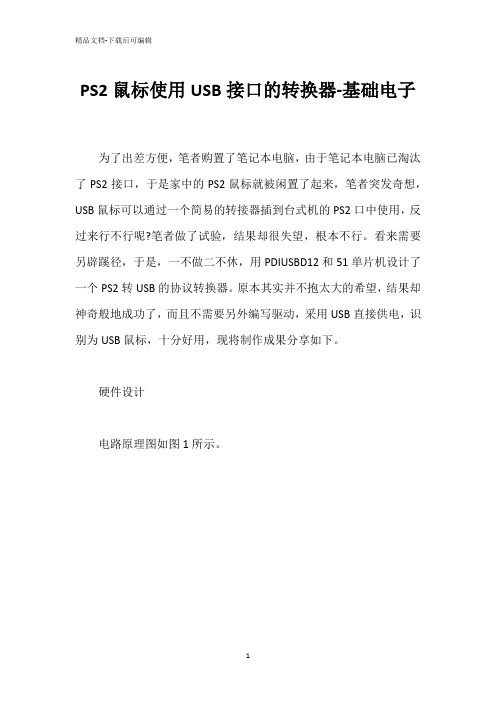
硬件设计电路原理图如图1所示。
其中鼠标PS2接口的引脚定义如图2。
电路的主体为ATMEL公司的51系列芯片ATMEL89S52(以下简称S52)和PHILIPS公司的并行传输USB接口芯片PDIUSBD12(以下简称D12)。
S52相信读者已经非常熟悉了,24MHz的主频,256字节的RAM,4组8位I/O口,没有什么特别的功能,一切中规中矩,本设计在此仅用到一个外部中断。
但这同时也说明,任何51内核(带总线)的单片机都可以适用。
PDIUSBD12是应用十分广泛的并行接口USB控制芯片,作为实现USB接口的标准组件,D12使设计者能够灵活选择合适的MCU,用经济快的方式实现USB外设的解决方案。
S52主要完成PS2接口鼠标的控制与数据获取,并通过PDIUSBD12与PC完成鼠标协议数据的传输。
为了精简电路,S52使用D12的可编程时钟源,通过编程输出高达24MHz的时钟,供S52使用;观察调试输出的Uart波特率需要为19200bps,便于快速输出信息,不耽误正常的USB枚举。
软件设计鼠标的工作模式有四种,分别为Reset模式,Wrap模式,Remote 模式和Stream模式。
前两种作为测试用,Remote模式为主机有需要时,发送命令使鼠标回送位移数据,Stream模式是上电的初始模式,每当鼠标产生位置或者按键状态的改变就自动发送数据。
HighTek HU-05 USB CAN 转 CAN 总线接口适配器 使用说明书
HighTek HU-05USB转CAN总线接口适配器使用说明书总目录第一章产品简介 (3)1.1概述 (3)1.2性能与技术指标 (3)1.3典型应用 (3)1.4产品销售清单 (4)1.5技术支持与服务 (4)第二章外形与接口描述 (5)2.1硬件接口描述 (5)2.2出厂配置 (5)第三章驱动安装与工具软件 (6)3.1驱动程序安装 (6)3.2CANTools软件安装与使用 (7)3.3CANTools试软件功能介绍 (10)第四章用户程 (12)4.1函数库中的数据结构定义 (12)4.2接口函数说明 (15)4.3接口库函数使用方法 (22)4.3.1VC调用动态库的方法 (22)4.3.2VB调用动态库的方法 (22)第五章附录 (25)附录1:CAN2.0B协议帧格式(可参考SJA1000CAN控制器) (25)第一章产品简介1.1概述HIGHTEK HU-05USB-CAN USB转CAN总线接口适配器是带有1路CAN接口和一路USB2.0接口的智能型CAN总线接口适配器,可进行双向传送。
采用该接口适配器,PC(或其他以太网设备)可以通过RJ45接口连接一个标准CAN网络,构建现场总线测试实验室、工业控制、智能楼宇、汽车电子等领域中数据处理、数据采集、数据通讯网络的CAN核心控制单元。
USB-CAN接口适配器可以被作为一个标准的CAN节点,是CAN总线产品开发、CAN总线设备测试、数据分析的强大工具;同时,USB-CAN接口适配器具有体积小、方便安装等特点,也是便携式系统用户的最佳选择。
USB-CAN接口适配器产品可以利用开发商提供的CANTools工具软件,直接进行CAN总线的配置,发送和接收。
用户也可以参考我公司提供的DLL动态连接库、例程编写自己的应用程序,方便的开发出CAN系统应用软件产品。
USB-CAN接口适配器设备中,CAN总线电路采用独立的DCDC电源模块,进行光电隔离,使该接口适配器具有很强的抗干扰能力,大大提高了系统在恶劣环境中使用的可靠性。
MOXA UPort 1200 1400 1600系列USB到串行转换器说明书
UPort1200/1400/1600Series2to16-port RS-232,RS-422/485,and RS-232/422/485USB-to-serial convertersFeatures and Benefits•Hi-Speed USB2.0for up to480Mbps USB data transmission rates•921.6kbps maximum baudrate for fast data transmission•Real COM and TTY drivers for Windows,Linux,and macOS•Mini-DB9-female-to-terminal-block adapter for easy wiring•LEDs for indicating USB and TxD/RxD activity•2kV isolation protection(for“-I”models)CertificationsIntroductionThe UPort®1200/1400/1600Series of USB-to-serial converters is the perfect accessory for laptop or workstation computers that do not have a serial port.They are essential for engineers who need to connect different serial devices in the field or separate interface converters for devices without a standard COM port or DB9connector.The UPort®1200/1400/1600Series converts from USB to RS-232/422/485.All products are compatible with legacy serial devices,and can be used with instrumentation and point-of-sale applications.SpecificationsUSB InterfaceSpeed12Mbps,480MbpsUSB Connector USB Type BUSB Standards USB1.1/2.0compliantSerial InterfaceNo.of Ports UPort1200Models:2UPort1400Models:4UPort1600-8Models:8UPort1600-16Models:16Connector DB9maleBaudrate50bps to921.6kbpsData Bits5,6,7,8Stop Bits1,1.5,2Parity None,Even,Odd,Space,MarkFlow Control NoneRTS/CTSXON/XOFFIsolation2kV(I models)Serial Standards UPort1410/1610-8/1610-16:RS-232UPort1250/1250I/1450/1650-8/1650-16:RS-232,RS-422,RS-485Serial SignalsRS-232TxD,RxD,RTS,CTS,DTR,DSR,DCD,GNDRS-422Tx+,Tx-,Rx+,Rx-,GNDRS-485-4w Tx+,Tx-,Rx+,Rx-,GNDRS-485-2w Data+,Data-,GNDSerial Software FeaturesWindows Drivers Windows11/10/8.1/8/7/Vista/XP/ME/98/95Windows Server2022/2019/2016/2012R2/2012/2008R2/2008/2003/2000/NT Linux Drivers Kernel versions:6.x,5.x,4.x,3.x,2.6.x and2.4.xMac Drivers macOS versions:10.12to10.15,11.xVirtual Machine VMware Fusion(Windows on macOS10.12to11.x)VMWare ESXi(Linux kernel4)Parallels Desktop(Windows on macOS10.12to11.x)Arm®-based Platform Support Linux kernel5.x/4.xAndroid API Android3.1.x and laterPower ParametersInput Voltage UPort1250/1410/1450:5VDC1UPort1250I/1400/1600-8Models:12to48VDCUPort1600-16Models:100to240VACInput Current UPort1250:360mA@5VDCUPort1250I:200mA@12VDCUPort1410/1450:260mA@12VDCUPort1450I:360mA@12VDCUPort1610-8/1650-8:580mA@12VDCUPort1600-16Models:220mA@100VACPhysical CharacteristicsHousing MetalDimensions UPort1250/1250I:77x26x111mm(3.03x1.02x4.37in)UPort1410/1450/1450I:204x30x125mm(8.03x1.18x4.92in)UPort1610-8/1650-8:204x44x125mm(8.03x1.73x4.92in)UPort1610-16/1650-16:440x45.5x198.1mm(17.32x1.79x7.80in) Weight UPort1250/1250I:180g(0.40lb)UPort1410/1450/1450I:720g(1.59lb)UPort1610-8/1650-8:835g(1.84lb)UPort1610-16/1650-16:2,475g(5.45lb)Environmental LimitsStorage Temperature(package included)-20to75°C(-4to167°F)Ambient Relative Humidity5to95%(non-condensing)Operating Temperature UPort1200Models:0to60°C(32to140°F)UPort1400//1600-8/1600-16Models:0to55°C(32to131°F)1.UPort1410/1450Models:5V for USB port power,12V for external power adapterStandards and CertificationsEMC EN55032/35EMI CISPR32,FCC Part15B Class AEMS IEC61000-4-2ESD:Contact:4kV;Air:8kVIEC61000-4-3RS:80MHz to1GHz:3V/mIEC61000-4-4EFT:Power:1kVIEC61000-4-5Surge:Power:1kVIEC61000-4-6CS:150kHz to80MHz:3V/mIEC61000-4-8PFMFSafety UPort1200/1600-16Models:UL60950-1UPort1400/1600-8Models:UL/IEC62368-1DeclarationGreen Product RoHS,CRoHS,WEEEMTBFTime UPort1250/1250I:563,179hrsUPort1410:394,441hrsUPort1450/1450I:546,770hrsUPort1610-8:208,413hrsUPort1650-8:186,567hrsUPort1610-16:138,704hrsUPort1650-16:120,001hrsStandards UPort1250/1250I/1410/1450/1450I:Telcordia(Bellcore)StandardUPort1610-8/1650-8/1610-16/1650-16:MIL-HDBK-217F WarrantyWarranty Period5yearsDetails See /warrantyPackage ContentsDevice1x UPort1200/1400/1600Series USB-to-serial converterCable1x USB type A male to USB type B maleConnectors1x Mini DB9F-to-TB(UPort1250/1450/1650models)Power Supply1x power adapter,universal(UPort1250I/1450/1450I/1600-8)1x power cord(UPort1600-16)Installation Kit1x rack-mounting ear(UPort1600-16models)Documentation1x quick installation guide1x warranty cardDimensionsUPort1250UPort1250IUPort1410/1450UPort1450IUPort1610–8/1650–8UPort1610–16/1650–16Ordering InformationModel Name USB Interface Serial Standards No.of Serial Ports Isolation Housing Material Operating Temp. UPort1250USB2.0RS-232/422/4852–Metal0to55°C UPort1250I USB2.0RS-232/422/48522kV Metal0to55°C UPort1410USB2.0RS-2324–Metal0to55°C UPort1450USB2.0RS-232/422/4854–Metal0to55°C UPort1450I USB2.0RS-232/422/48542kV Metal0to55°C UPort1610-8USB2.0RS-2328–Metal0to55°C UPort1650-8USB2.0RS-232/422/4858–Metal0to55°C UPort1610-16USB2.0RS-23216–Metal0to55°C UPort1650-16USB2.0RS-232/422/48516–Metal0to55°C Accessories(sold separately)CablesCBL-USBA/B-100USB2.0cable,type A-to-type B,1mCN2007010-pin RJ45to DB9female serial cableNP21101DB25male to DB9female cable for RS-232transmission,30cmCBL-F9M9-20DB9female to DB9male serial cable,20cmCBL-F9M9-150DB9female to DB9male serial cable,1.5mCBL-RJ45SF9-1508-pin RJ45to DB9female serial cable with shielding,1.5mConnectorsMini DB9F-to-TB DB9female to terminal block connectorADP-RJ458P-DB9F DB9female to RJ45connectorA-ADP-RJ458P-DB9F-ABC01DB9female to RJ45connector for the ABC-01SeriesMounting KitsDK-UP1200DIN rail(25x48.3mm)with2screws(FMS M3X6)Applicable Models:UPort1250DK-UP1400DIN-rail/wall-mounting kit,2plates,6screws,and2DIN-rail plates,4screwsApplicable Models:UPort1410UPort1450UPort1450IUPort1610-8UPort1650-8DIN-Rail Mounting KitsDK-UP-14168DIN-rail kit with2plates(89x19mm),6screws(FMS M3x5mm)for the UPort1400(V1.5.0and after)and1600-8(V1.4.0and after)modelsApplicable Models:UPort1410UPort1450UPort1450IUPort1610-8UPort1650-8Wall-Mounting KitsWK-35-02Wall-mounting kit with2plates(35x24x1.2mm)and6screwsApplicable Models:UPort1250UPort1250IWK-35-01Wall-mounting kit with2plates(35x44x2.5mm)and6screwsApplicable Models:UPort1410UPort1450UPort1450IUPort1610-8UPort1650-8WK-UP-14168Wall-mounting kit with2plates(35x44mm),6screws(FMS M3x4mm)for the UPort1400and1600-8modelsApplicable Models:UPort1410UPort1450UPort1450IUPort1610-8UPort1650-8Rack-Mounting KitsWK-45-01Rack-mounting kit,2L-shaped plates,6screws,45x57x2.5mmApplicable Models:UPort1610-16UPort1650-16Power AdaptersPWR-12150-WP-S4Locking barrel plug with12VDC,1.5A,100to240VAC,without plug,0to40°C operating temperatureApplicable Models:UPort1250UPort1250IUPort1410UPort1450UPort1450IUPort1610-8UPort1650-8Power CordsPWC-C13EU-3B-183Power cord with EU/KR plug,1.83mApplicable Models:UPort1610-16PWC-C13US-3B-183Power cord with US plug,1.83mApplicable Models:UPort1610-16UPort1650-16PWC-C13CN-3B-183Power cord with three-prong CN plug,1.83mApplicable Models:UPort1610-16UPort1650-16PWC-C13JP-3B-183Power cord with JP plug plug,7A/125V,1.83mApplicable Models:UPort1610-16UPort1650-16PWC-C13UK-3B-183Power cord with UK plug,1.83mApplicable Models:UPort1610-16UPort1650-16PWC-C13AU-3B-183Power cord with AU plug,1.83mApplicable Models:UPort1610-16UPort1650-16©Moxa Inc.All rights reserved.Updated May17,2023.This document and any portion thereof may not be reproduced or used in any manner whatsoever without the express written permission of Moxa Inc.Product specifications subject to change without notice.Visit our website for the most up-to-date product information.。
串口并口转USB以太网透传模块
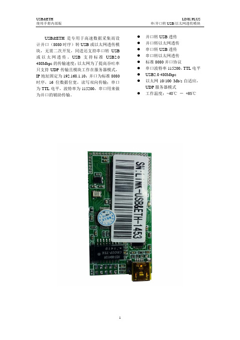
USBÐ 是专用于高速数据采集而设计并口(8080时序)转USB 或以太网透传模块,无需二次开发,同进还支持串口转USB 或以太网透传。
USB 支持标准USB2.0 480Mbps 的传输速度;以太网为了提高吞吐率只支持UDP 传输且模块工作在服务器模式,IP 地址固定为192.168.1.10;并口为标准8080时序,16位数据位宽,读写双向传输;串口为TTL 电平,波特率为115200,串口用来做为并口的辅助传输。
● 并口转USB 透传 ● 并口转以太网透传 ● 串口转USB 透传 ● 串口转以太网透传 ● 标准8080并口协议 ● 串口波特率115200,TTL 电平● USB2.0 480Mbps●以太网10/100 Mb/s 自适应,UDP 服务器模式● 工作温度:-40℃ - +85℃1.引脚定义[1] I输入,O输出,I/O输入输出,P电源USB(J2)引脚定义备注1 VBUS +5V2 DM 差分数据对3 DP4 GND 地网口(J3)引脚定义备注发送差分信号数据对1 TD+2 TD-3 LED_ACT+ LED正4 LED_LINK+接收差分数据对5 RD+6 RD-7 LED_ACT- LED负8 LED_LINK-9 NC 保留10 NC2.模块封装单位:mm3.电气参数名称最小值典型最大值单位供电电压(VCC) 3.0 3.3 3.6 V供电电流(I) 80 120 160 mA 输入低电平0 -- 0.8 V(V IL )[1] 输入高电平(V IH )2.0 -- VCC V[1] 所有I 引脚都兼容5V 电平4. 参考电路注电容越靠近模块放越好,其它I/O 接口最好串入10Ω到50Ω电阻。
5. 详细说明 5.1 上电时序如上图所示,模块上电并初始化完成t1(约50ms )时间后,RES 输出t2(约10ms )时间宽度的低电平复位从设备。
5.2 读写时序+3.3VVCCGND模块10uF/10V0.1uFRST RES INT AddrRD WR D[15…0]VCC5.3 并口转USB从并口传数据到USB当有数据时置INT为低电平,模块开始读取数据。
BC7210A USB 接口红外解码板 使用说明书
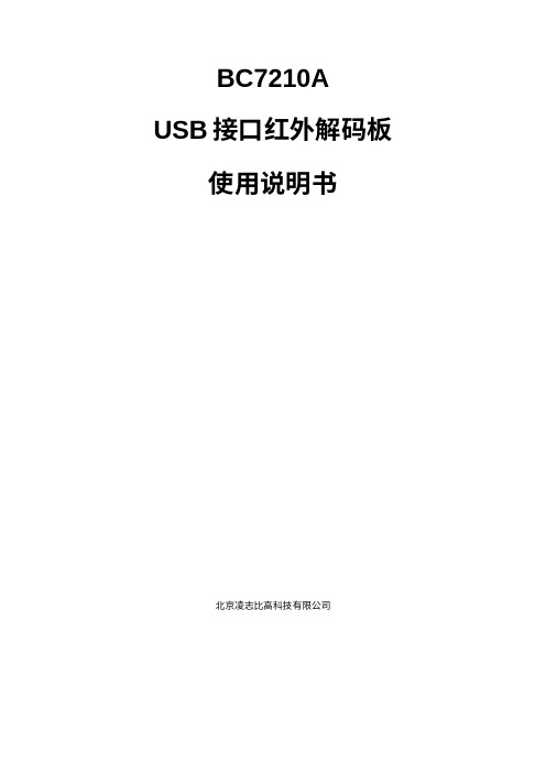
BC7210A USB接口红外解码板使用说明书北京凌志比高科技有限公司原理图:BC7210A USB 接口解码板,使用BC7210A 芯片和USB-UART 转换芯片构成一个完整的红外遥控解码系统,直接连接计算机USB 接口,即可将接收到的红外遥控指令解码并将数据传送给计算机。
同时,板上留有供外接用户电路的接口,所有BC7210A 输出的信号,均可引出,在用户主机不是计算机而是用户自有系统的时候,可以直接连接用户电路使用,用于测试BC7210A 的性能,以便日后在系统中直接使用BC7210A 芯片。
板上使用的USB-UART 转换芯片,是HOLTEK 公司的HT42B534,该芯片连接计算机后,呈现为一个串口设备。
在Windows 10, Linux 及Mac OS 操作系统下,可以自动加载驱动程序,无需用户干预,实现即插即用。
在Windows 8及以前的操作系统中,初次使用需安装驱动程序,用户可前往HOLTEK 公司的官网下载。
(中文网页:https:///productdetail/-/vg/42B534-x ; 英文网页:https:///productdetail/-/vg/42B534-x )。
如发现安装驱动程序后仍无法使用,很可能是因为在安装驱动前已经将解码板连接到计算机,系统没能加载正确的驱动程序所导致,只需到“设备管理器”中将设备卸载,再重新连接USB 接口即可。
解码板的数据输出格式为:波特率9600, 8个数据位,1位停止位,无奇偶校验位,无流控制。
BC7210A 有两种工作模式:NEC 模式和RC5模式,分别对应两种红外遥控的编码格式。
本解码板电路默认工作于NEC 模式,如果用户需要使用RC5模式,可以自行在板上焊上3针连接器,用跳线将2-3脚短接即可(如图)。
在NEC 模式下,每次输出3个字节,第一个至第三个字节分别为:地址码高8位,地址码低8位,按键码。
第一字节第二字节第三字节b 7b 6b 5b 4b 3b 2b 1b 0b 7b 6b 5b 4b 3b 2b 1b 0b 7b 6b 5b 4b 3b 2b 1b 0A 15A 14A 13A 12A 11A 10A 9A 8A 7A 6A 5A 4A 3A 2A 1A 0D 7D 6D 5D 4D 3D 2D 1D设置为RC5模式而在RC5模式下,每次输出2个字节,地址码为第一个字节的低3位加上第二个字节的高2位,按键码为第二个字节的低6位。
ft4232hl的规格书
ft4232hl的规格书FT4232HL是一款由FTDI公司生产的USB接口转换器芯片,它可以将并行或SPI 接口转换为USB接口,实现与计算机的连接。
以下是FT4232HL的规格书:概述FT4232HL是一款高性能、低成本的USB接口转换器芯片,可以将并行或SPI接口转换为USB接口,实现与计算机的连接。
它具有高速、稳定、简单易用的特点,广泛应用于各种需要将串行或并行数据转换为USB接口的设备中。
特性•高速传输:支持USB 2.0协议,最高传输速率可达480Mbps。
•自动检测:能够自动检测连接的设备类型,实现即插即用。
•兼容性好:支持Windows、Linux、macOS等操作系统,无需安装驱动程序。
•多功能:支持8位并行接口和SPI接口,具有可编程的时钟频率和数据宽度。
•安全可靠:内置加密算法,保护数据安全。
•体积小巧:封装尺寸仅为16mm x 16mm x 0.8mm。
1.电气特性•工作电压:USB总线供电,5V直流电压。
•电流消耗:最大值为500mA,工作电流为300mA左右。
•输入输出电平:符合USB规范,输出电平为3.3V和5V。
1.机械特性•封装形式:表面贴装16mm x 16mm x 0.8mm封装。
•引脚间距:0.5mm。
•引脚定义:根据不同应用场景,可选择不同的引脚定义。
应用范围FT4232HL适用于各种需要将串行或并行数据转换为USB接口的设备中,如打印机、扫描仪、摄像头、GPS接收机等。
它还适用于开发板和嵌入式系统的设计,方便开发者快速搭建USB接口转换应用。
使用方法使用FT4232HL非常简单,只需将其连接至计算机的USB端口,然后将需要转换的并行或SPI接口与FT4232HL连接即可。
FT4232HL会自动检测连接的设备类型,实现即插即用。
用户可以通过开发应用程序来实现对FT4232HL的控制和数据传输。
注意事项•在使用FT4232HL时,应注意不要将其置于高温环境中使用,以免过热损坏芯片。
