Agilent_0729_presentation
安捷伦炼厂气分析仪说明书
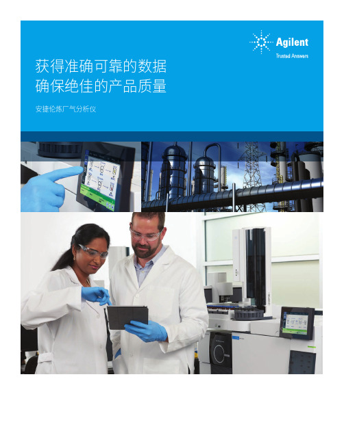
2安捷伦炼厂气分析仪助您可靠监测和优化催化及其他工艺安捷伦炼厂气分析仪 (RGAs) 基于 Agilent 8890 气相色谱系统。
每套系统均在出厂前经过配置和化学测试,可快速提供您所需的分析结果,同时节省您宝贵的启动时间。
您可以从扩展炼厂气、快速炼厂气、不凝气和烟道气分析的标准配置中进行选择,还可以基于 8890 气相色谱仪或 990 微型气相色谱仪定制炼厂气分析仪,以满足您的特定需求。
准确地分析炼厂气极具挑战性,因为各种气体样品的原料和组成差异很大。
为成功应对挑战,分析仪必须快速将各种炼厂和石化气体样品中的复杂混合物分离开来。
应用新型气相色谱技术,无需打乱应用工作流程Agilent 8890 气相色谱系统Agilent 990 微型气相色谱系统3安捷伦 RGAs 体现了行业标准和严格的质量控制流程每台分析仪都包括:出厂前–系统配置和泄漏检测–仪器校验 –安装合适的色谱柱–使用应用校验混标运行出厂前化学校验交付–运行方法所需的仪器操作手册 –含方法参数和校验数据文件的 DVD ,便于上手–包括消耗品,无需单独订购 –消耗品信息,以便再次订购安装–使用校验样品重复出厂校验,由经过厂家培训的支持工程师现场实施–可选的应用启动帮助智能互联气相色谱仪,与您同舟共济作为一款全新的气相色谱仪器,安捷伦NGAs 可自动监测系统健康状况、为您提醒潜在隐患,并助您随时解决问题。
这样您可以游刃有余地规划工作(包括维护),无需应对意外停机。
此外,该分析仪采用微流路电子气路控制模块 (EPC)。
这种安捷伦独有的设计可防止颗粒、水汽和油等污染物对 EPC 的损害,并提高仪器的可靠性和使用寿命。
最重要的是,您可以随时随地查看您的实验室。
移动访问功能让您可以随时查看设置信息、进行仪器诊断并解决故障、检查泄漏、实现色谱柱反吹功能、暂停和启动样品运行,并管理方法开发进程。
采用 Agilent 8890 快速 RGA 运行校验样品。
Agilent 电池测试指南

图 1. 一般测试配置
表 1. 不同类型电池的特性和应用
镍镉电池
电压 / 电池 1.2
应用
便携式设备,
可充电
酸性胶质电池 2.0 后备服务, 可充电
充电方法 循环寿命 寿命 (充电后) 工作温度 性能特点
CC 500 次以上 3 个月 (-2%/ 天) 20 至 70℃ 高放电率 快充电率
CV,浮置充电 200 次 1年
让电池经过5次相继的充电_放 电稳定化循环,得到平均容量和最 大容量。电池在环境温度 23℃下经 历包括充电、放电和休息的5次稳定 化循环。电池在 20 至 24 小时周期内 以 C/10 充电,休息 2 至 4 小时,然 后以1C安培的恒流放电,直到 0.9V 的 EODV。
图 3. 放电率对容量的影响
从到现在为止的各种不同测试 描述,我们能看到对测试设备的一 些共同要求。所有测试都需要一个 使用恒流的放电周期。由于电池电 压因电流的流出而改变,因此简单 的电阻器不能实现电流的恒定。需 要使用有源装置,例如具有恒流工 作模式的电子负载。还应注意由于 不同测试需要不同大小的恒定电流, 所以您要能按测试要求动态控制电 子负载。
循环50次的容量应不低于制造 商所给的指标。
长期过充电
电池承受过充电的能力由 C/10 恒流对电池的充电确定,或制造商 所给的 6 个月、环境温度 23℃下的 最大过充电率。电池不得有电解液 泄漏,或能看到超过标准最大尺寸 的电池变形。当以恒流 1C 放电到 0. 9V 的 EODV 时,电池容量应等于 或大于长期过充电容量指标。
Agilent AN 372-2 电池测试
应用指南
可用电子负载给各种化学电池放电, 以确定实际容量,容量残留和内阻。
Agilent 6000 系列 LC MS 安全指南说明书
Agilent 6000 系列 LC/MS安全指南安全2仪器上的标志2通用仪器安全5人身伤害安全6常规化学品安全9化学废弃物安全10生物危险品安全11符合性和标准12安全与规范认证12电磁兼容性13环境条件14声音发射声明14本指南包含有关 Agilent 6000 系列 LC/MS 的安全性、符合性和标准的信息。
当处理溶剂和化学品或未装配的部件时,请始终穿戴适当的防护用品,包括护目用具、实验室工作服和手套。
安全仪器上的标志安全仪器上的标志电气标志下表描述了可在 LC/MS 仪器上显示的电气标志。
表 1电气标志标志说明表示受保护的接地端。
断路器。
交流电流保险丝安全仪器上的标志安全标志下表描述了可在 LC/MS 仪器上显示的安全标志。
每个标志单独出现,或与用于解释相关危险的文本一起出现。
这些安全标志还可能出现在危险、警告或小心提示的旁边。
表 2安全标志标志说明或对于标有此标志的仪器,用户应参阅说明手册,以免对操作员造成伤害并防止损坏仪器。
表示危险电压。
如果较热表面可触及并且用户不应在加热后接触该表面,则仪器上会标有此标志。
设备放电 (ESD) 危害。
爆炸危险。
安全仪器上的标志在有氢气或者任何其他易燃气体或烟雾存在时,不要操作仪器。
在这类环境中操作任何电子仪器会造成一定的安全隐患。
不要将该电气/电子产品丢弃在家庭垃圾中。
在更换保险丝之前,需从电源插座断开电源插头。
两条带电电路。
在进行维护之前,断开两根电源线。
生物风险表 2安全标志(续)标志说明安全通用仪器安全通用仪器安全人身伤害危险:仅按照用户说明中指定的方式使用 LC/MS 仪器。
如果不按照Agilent Technologies 指定的方式使用系统,可能会导致人身伤害或仪器损坏。
移动或抬起系统人身伤害危险:LC/MS 仪器很重。
至少需由两个人抬起 6100 系列 LC/MS 仪器。
至少需由四个人抬起 6200、6400 和 6500 系列 LC/MS 仪器。
气相色谱仪操作及维护保养规程(安捷伦7820)

气相色谱仪操作及维护保养规程(安捷伦7820)___ 7820Instrument n:The gas chromatograph in the testing lab is an Agilent 7820A or 6820 model。
with the main n parameters listed in Table 1.The 6820 model gas chromatograph lacks EPC control n。
but its other nal modules and structure are the same or similar to those of the 7820A.Table 1: Main n of Agilent ___NumberSample InletDetectorCapillary GC ColumnAutomatic SamplerGas SourceRemarksn:2.1 Work EnvironmentThe temperature range in the lab should be een 10℃ and 30℃。
with a relative humidity of 40% to 85%。
Avoid direct sunlightand do not place the ___.2.2 Gas Source nBefore daily work。
confirm the following:a) First。
___。
___ stem (valve switch: counterclockwise to open)。
with a full bottle pressure of 15MPa。
The remaining pressure in the steel cylinder should not be less than 2MPa。
otherwise it ___.b) There are two pressure cing valves in each gas pipeline (one at the outlet of the steel cylinder。
Agilent7000B培训手册

Agilent7000B培训手册Agilent GC_QQQ现场培训教材目录第一章串联四级杆气相质谱仪工作原理 (3)1.1 气相色谱1.2 离子源1.3 四级杆质量分析器1.4 碰撞池1.5 检测器1.6 Masshunter 软件第二章安捷伦7000B 气相串联质谱仪开关机步骤及调谐 (8) 2.1 安捷伦7000B气相串联质谱仪配置2.2 质谱仪开机步骤2.3 质谱调谐2.4 质谱仪空气检漏2.5 质谱仪关机步骤第三章串联质谱扫描模式及及数据采集方法编辑运行 (13) 3.1 安捷伦串联四级杆可设定的扫描模式3.2 串联质谱运行方法编辑3.2.1 气相配置设定3.2.2 编辑运行方法的气相参数(包含碰撞池气体流量设定)3.2.3 运行方法质谱参数设定3.3 单个质谱方法运行3.4 Sequence 自动进样序列表设定及运行第四章 MRM 方法开发概诉 (24)4.1 多重反应监测(MRM)的详细过程4.2 MRM方法的开发过程4.3 如何使用QQQ方法优化助手第五章定性分析 (27)5.1 了解定性分析的基础知识5.1.1工具栏5.1.2数据文件浏览5.1.3色谱图窗口5.1.4浏览数据点5.1.5获得质谱图5.1.6质谱图扣背景5.1.7方法编辑窗口5.2全扫描数据的定性分析5.2.1积分5.2.2定义色谱图5.2.3 计算信噪比Agilent GC_QQQ现场培训教材 5.2.4查找和识别化合物5.2.5谱库检索5.2.6输出报告5.2.7谱图显示选项第六章定量分析 (39)6.1创建定量的批处理和定量方法6.1.1 新建batch6.1.2向 Batch中引入数据文件6.1.3检查/补充定量数据的信息6.2新建定量方法6.2.1 MRM Compound setup6.2.2 Retention Time Setup6.2.3 ISTD Setup6.2.4 Concentration Setup6.2.5 Qualifier Setup6.2.6 Calibration Curve Setup6.2.7 定量高级功能设定--- 积分参数6.2.8 离群数据范围设置6.2.9 Validate method6.2.10 退出并保存定量方法6.3 数据分析6.3.1 Analyze Batch6.3.2校正曲线的修改6.3.3定量表中的提示符号6.3.4 保存batch6.4 定量报告Agilent GC_QQQ现场培训教材第一章串联四级杆气相质谱仪工作原理安捷伦串联气相质谱仪由六个部分组成,分别为:1.气相色谱部分2.离子源3.第一极四级杆及第二级四级杆4.碰撞池5.检测器6.Masshunter 软件7890气相色谱仪1.1 气相色谱对于质谱仪来说,气相色谱主要是进样仪器。
Agilent FieldFox 微波分析仪快速参考指南说明书
Agilent FieldFoxMicrowave AnalyzersQuick Reference GuideContentsDo You Have Everything? (2)The Power Button and LED (2)Battery Usage (3)Measure Return Loss (CAT) (4)Measure 1-Port Cable Loss (CAT) .5 Measure DTF (CAT) (6)Measure S-Parameters (NA) (7)Multi-Trace Configurations (NA) (9)Calibration (CAT, NA, VVM) (10)Spectrum Analyzer Mode (SA) (11)Channel Measurements (SA) (12)Record Playback (SA) (13)Power Meter Mode (14)Save and Recall Files (15)Manufacturing Part Number: N9927-90002Print Date: June, 2012©Agilent Technologies, Inc.Do you have everything?☐–☐Phase stable jumper cable or adapters– Used to connect the FieldFox to devices with variousconnector types and gender.☐Attenuators– Reduces power and prevents damage to the FieldFox at the RF IN port.☐Cal Kit– OSL Tee or other calibration devices. ☐SD card or USB flash drive– Save files to these devices for quick download to a PC.☐USB Power Sensor– For making Power Meter measurements. (Opt 302)☐Battery charger or extra batteryThe Power Button and LED▪To turn power ON, briefly press the power button.The LED is green. The boot-up takes about 60seconds.▪To switch to Stand by power (low battery drain)briefly press the power button. The LED is amberand blinks slowly. To turn power ON, briefly press the power button. Power and settings are restored instantly.▪To turn Power OFF (very low battery drain) press and hold the power button until power is shut OFF - about 4 seconds. The LED is OFF.Battery UsageA fully charged battery should last about four hours.Battery charge status is viewable:▪In the upper-right corner of the screen.▪On the battery. To view the LCD gauge on theInspired Energy battery, open the FieldFox battery compartment door.To conserve battery power:▪when needed. Hold is shown on the display.▪▪Briefly press the power button to switch to Standby mode when not being used. Press again torestore power. All current settings are preserved.The FieldFox will shutdown automatically when battery power is very low to prevent it from being completely discharged.Use ONLY a FieldFox charger to recharge a battery.The battery can be fully charged while in the FieldFox in about 4 hours with the FieldFox either ON or OFF.A fully discharged battery takes about 1.5 hours to recharge to 80%.The battery can be fully charged in about 4 hours using the external battery charger (Opt 872).Measure Return Loss (CAT Mode)Return loss can be thought of as the absolute value of the reflected power as compared to the incident power.When measuring an OPEN or SHORT, all incident power is reflected and 0 dB return loss is displayed.When measuring a LOAD, very little power is reflected and values of 40 dB to 60 dB are displayed.1.Connect the Device Under Test (DUT).2.3.4.5.6.7.the calibration prompts.8.Reconnect the DUT (cable to be tested).Optional▪Add Markers – All Modes except VVM and PowerMeter▪Add Limits – All Modes except VVM and PowerMeter▪Save Settings and Data – All ModesMeasure 1-Port Cable Loss (CAT Mode) Required Equipment:▪LOAD with correct connector type and gender to terminate the end of the DUT.▪Optional phase stable jumper cable or adapter to connect the beginning of the DUT to the FieldFox.1.2.3.4.5.6.7.FieldFox and connect a LOAD at the end of theDUT.Depending on the DUT, the following three steps may improve the amount of ripple visible on the screen.8.9.10.11.Read Avg Cable Loss on the FieldFox screen.Measure Distance to FaultRequired Equipment:▪LOAD with correct connector type and gender toterminate the end of the DUT.▪Known length and cable type or Cable Loss(dB/Meter) and velocity factor of the DUT.▪Optional phase stable jumper cable or adapter toconnect the beginning of the DUT to the FieldFox.1.Connect any necessary jumper cable or adapter tothe FieldFox RF OUT port.2.3.4.5.6.7.8.Disconnect any components or antenna that shouldNOT be measured and connect a LOAD at the end of the DUT.9.11.Connect the start end of the DUT to the FieldFox.The DTF measurement is displayed.Measure S-Parameters (NA Mode)S-parameter syntax is described by the following: S (out | in)out = FieldFox receiver portin = FieldFox source port▪▪▪▪more time to sweep.data points requires more time to sweep.Continued on following page…Measure S-Parameters (NA Mode) continued The following NA Mode settings can be made before or after calibrating without affecting measurement accuracy.▪▪Adjusts the Y-axis to comfortablytrace.▪Autoscales all of the traces onconfigurations.▪scale per division to▪▪line) and 10 (BOTTOM line)▪▪▪▪Multi-Trace Configurations (NA Mode)You can display multiple traces on the FieldFox screen.The above image shows a 3-trace configuration. Tr1 is the ACTIVE trace as indicated by the highlighted Tr1 annotation in the upper left corner.The Frequency Range, IF BW, Resolution, Averaging, and Output power is common to all traces. All trace settings, such as format, markers, and limit lines, are applied to the ACTIVE trace in the same manner as when a single trace is present.To select a multi-trace configuration:▪▪Then choose a multi-trace configuration.To activate a trace in order to change a setting:▪ to scroll through the traces -OR▪By default with Multi-trace configurations, Markersthat are applied to one trace are applied to ALL traces.CalibrationCalibration is performed in CAT, NA, and VVM Modes.A calibration is performed automatically when the FieldFox is powered ON and when Preset. This Preset Cal (also known as CalReady) sets the reference plane at the RF OUT connector.For highest accuracy, perform a QuickCal or O,S,L when any of the following occur:▪The temperature changes significantly.▪The Frequency Range, Resolution, Min Swp Time, or Power Level is changed.▪When using a phase stable jumper cable or adapter to connect the DUT to the FieldFox. These shouldbe high-quality components.is shown on the screen when a Preset Cal is correcting the measurement.is shown on the screen when a QuickCal is correcting the measurement.is shown on the screen when an O,S,L Cal is correcting the measurement.When a calibration is being interpolated, an asterisk is added to the screen annotation as follows:Spectrum Analyzer (SA) ModeSA measurements require NO calibration.Check for a Compressed Measurementing a marker at the signal peak, make note of thesignal power level.2.Increase the RF Attenuation level by 5 dB.▪If the signal level does NOT change, then NOcompression exists. This indicates that the signal is in the linear region of the receiver.▪If the signal level DOES increase with moreattenuation, then compression DID exist. Set theRF Attenuation value at the setting when furtherincreases no longer result in an increase in thedisplayed power level.Set RF Attenuation1.2.3.▪▪Display up to four types of tracesSA settings are applied to all traces.1.2.SA Mode – Channel MeasurementsOptionally apply a Radio Standard which changes frequency settings, Res BW, and other relevant settings to that of the selected standard. Then change the frequency range by selecting channel numbers.1.2.3.4.5.6.▪Channel Power (CHP) - Measures total power over the specified Integrated BW.▪Occupied Bandwidth (OBW) - Measures the power of the current frequency span and displays vertical posts between which the specified percentage ofpower is contained.▪Adjacent Channel Power (ACPR) - Measures thepower of a carrier channel and one, two, or three adjacent (offset) channels.▪Tune and Listen (AM/FM)– Plays potentiallyinterfering AM or FM signals through the FieldFox speaker or headphones.Record Playback (Opt 236)Allows you to record SA traces and play them back at a later time. You are allowed to change most SA settings during a recording. Setting changes are recorded along with the traces.To record a new session:▪– limits record time.▪– choose where in the FieldFox easiest.▪– sets the amount of time to wait▪– sets the number of traces to▪– sets the power level which will To play a session:The maximum recording time is determined largely byPower Meter ModePower Meter measurements are made using the Agilent U2000 Series USB Power Sensors.Damage levels are:▪+25 dBm (320 mW) average▪+33 dBm peak (2 W) <10μs▪+5VUse an Attenuator between the DUT and the power sensor when measuring power levels that are higher than +20 dBm. The attenuator value can be subtracted from the measurement using Offset as follows:Select Offset▪▪compensates for a component with loss, such as an attenuator.ZeroingThe Agilent USB Power Sensors perform internal zeroing automatically. Internal zeroing does NOT require that the power source be turned OFF. Perform external zeroing when measuring power levels below -30 dBm. During external zeroing, the power source MUST either be turned OFF or the power sensor be disconnected from the DUT.▪▪Save and Recall FilesSave current settings and calibration, trace data (CSV) and .S1P), or a picture of the FieldFox screen.1.LOCATION where▪▪▪2.▪▪file.▪▪CAT and NA Mode trace data to▪3.file type to.4.。
Agilent-GCMS培训优秀课件
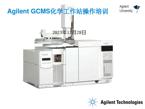
5973 旳放气 阀位置
46
质谱旳本地控制面板
• 诊疗 • 放空 / 抽真空 • 调谐 • 运营 / 停止
47
第三章 调 谐
48
主要内容
• MS调谐旳基本原理 • 化学工作站中旳不同调谐
49
调谐做什么?
▪ 设定离子源部件旳电压,以得到良好旳敏捷度 ▪ 设定 amu gain 和 amu offset 以得到正确峰宽 ▪ 设定 mass gain 和mass offset以确保正确旳质量分配 ▪ 设定 EM 电压
22
常见元素同位素表
元素
A
质量 %
H 1 100
P 31 100
F 19 100
I 127 100
C 12 100
N 14 100
O 16 100
S 32 100
Si 28 100
Cl 35 100
Br 79 100
A+1 质量 %
2
0.05
13
1.1
15
0.37
17
0.04
33
0.80
29
5.1
31
总离子流色谱
Abundance 8000000
TIC: ALKDEMO.D
33
34
6000000
32
4000000 2023000
31 30
35 36
Time 5.25 5.26 5.27 5.28 5.29 5.30 5.31 5.32 5.33
AbundanceScan 32 (5.281 min): ALKDEMO.D
26
四极杆
27
高能打拿极和电子倍增器
四级杆
Agilent 8890 5977C Series gas chromatograph mass s

Agilent 5977C GC/MSD SystemThe Agilent 8890/5977C Series gas chromatograph/mass selective detector (GC/MSD) builds on a tradition of leadership in GC and MS technology, with the world’s most competitive performance and productivity features.Agilent GC/MSD system featuresAgilent 5977C GC/MSD — the most sensitive and robust MSD provides:–Four EI source options including the revolutionary high-efficiency source (HES), which offers the industry’s lowest instrument detection limit (IDL) and bestcarrier gas applications.signal-to-noise ratio (S/N) and a HydroInert source for H2– A heated monolithic quartz gold quadrupole (heatable up to 200 °C) for rapid elimination of contamination to keep the analyzer clean.– A second-generation triple-axis detector (TAD) for eliminating neutral noise.–Scan speeds up to 20,000 u/sec (extractor ion source and HES).–An optional oil-free IDP-3 roughing pump: a cleaner, quieter, and greener alternative (for use with turbo molecular pump systems).10-Year value promiseSupport is guaranteed for 10 years from the date of purchase, or Agilent will provide credit for the residual value of the system toward a model upgrade.Installation checkout specifications Agilent verifies GC/MSD system performance at the customer site.IDL is a statistically based metricthat more accurately confirms system performance than an S/N measurement. Test specificationsare based on splitless injection intoan Agilent J&W HP-5ms Ultra Inert30 m × 0.25 mm, 0.25 μm column for helium and a 20 m × 0.18 mm, 0.18 μm column for HydroInert with hydrogen. IDL analyses use lab helium (hydrogen for HydroInert) with GC gas filters installed. See more about the IDL test at /Library/ technicaloverviews/Public/5990-8341EN.pdf* IDL was statistically derived at 99% confidence level from the area precision of eight sequential splitless injections of OFN (octafluoronaphthalene). Demonstration of IDL specifications require a compatible system configuration, including a liquid autosampler with a 5 μL syringe.–HES IDL was measured using 10 fg injection, 1 µL injection.–Other IDLs were measured using 100 fg, 1 µL injection.–A 30 m column was used for helium IDL checkout; a 20 m column was used for hydrogenIDL checkout.–Helium carrier gas for Installation Specifications of the HES, Extractor, and Stainless steel sources; hydrogen carrier gas for Installation Specification of the HydroInert source only.–Reference IDL specifications from the above table will be confirmed only when purchased as an additional service with a compatible new system (GC and MS) installation.Signal-to-noise (S/N) specificationsa S/N checkout is performed only if there is no compatible autosampler (which is required for IDL checkout). Helium carrier gas, manual injection using a 30 m × 0.25 mm,0.25 µm column and in scan mode. Hydrogen carrier gas, manual injection using 20 m × 0.18 mm, 0.18 µm column and in scan mode. When the autosampler (ALS) is present, these specifications are a reference of the performance. Reference S/N specifications from the above table will not be confirmed at installation or introduction for ALS equipped systems.b Standard scanning from 50 to 300 u at nominal 272.0 u ion.c 1 μL injection of 100 pg/μL benzophenone (BZP) standard, 80 to 230 u scan at nominal 183 u ion, using methane reagent gas.d 2 μL injection of 100 fg/μL OFN standard scanning from 50 to 300 u at nominal 272 u ion, using methane reagent gas.2a Only applicable with optional Accurate Mass software package. Scan mode only. Not verified during installation.b As scan rate increases, sensitivity will decrease, and resolution may degrade.c A high flow rate into a fixed ion source will cause a loss in sensitivity.d The heated quadrupole mass filter should not require maintenance, but if maintenance is required, it should be performed by an Agilent service engineer.34aInlet temperature should be cool enough to touch when performing maintenance.bA micro ion gauge is shipped standard for the CI system, and is available optionally for EI systems.DE67854286This information is subject to change without notice.© Agilent Technologies, Inc. 2022Printed in the USA, May 26, 20225994-4846EN。
安捷伦气相

72
6 对自定义解决方案的影响
73
宏解决方案
74
自定义工具栏
74
自定义菜单栏
74
对化学工作站宏的数据结构的影响
74
专有文件夹创建启用
74
专有文件夹创建关闭
75
升级准备指南
7
7 附录
77
化学工作站报告
概述
78
示例色谱 1
示例色谱 2
78
78 78
索引
81
内容提要
84
8
升级准备指南
安捷伦化学工作站 化学工作站 B.03.01 版升级准备指南
版本
2007 年 2 月 德国印刷
Agilent Technologies Hewlett-Packard-Strasse 8 76337 Waldbronn, Germany
软件修订版
1. 本指南适用于安捷伦化学工作站软件 B.03.0x 版。
2. 本指南中所有关于 A.0X.0X/B.01.03 版 本以及 16 位版本化学工作站的内容 都仅适用于英文版。
34
使用附加解决方案从化学工作站 B.0x.0x 版进行升级
34
常规附加解决方案
36
ChemStore (最高为 B.03.02)
36
ChemStore (B.03.02 SR1 以上)
36
安全软件包
36
LC 特定的附加解决方案
37
GC 特定的附加解决方案
38
保留时间锁定
38
助手
38
顶空
38
配置您的仪器
39
40
4 首次启动化学工作站 B.03.01 版
液质联用仪原理及操作注意事项安捷伦ppt课件
高效液相色谱质谱联用(HPLC/MS)是指高效液 相色谱与质谱串联的技术,是将应用范围极广的 高效液相分离方法与灵敏、专属、能够提供分子 量和结构信息的质谱法结合起来的一种现代分析 技术。
HPLC-MS主要由HPLC仪、接口离子源(LC与MS连接装置)、 质量分析器、真空系统、计算机数据处理系统组成。
四、故障排除
信号低 质量准确度差 雾化器出口是小 液滴而不喷雾
1.确保雾化气压设定 足够高以利液相色谱 流动相气化 2.检查雾化器中针头 的位置 3停止溶剂流动,卸 下雾化装置,检查雾 化器末端是否损坏
无液流
1.检查溶液化学性质,确 定样品溶剂是合适的 2.保证用新样品,并且正 确存储样品 3.检查雾化器条件 4.清洁毛细管入口 5.检查毛细管有无损坏和 污染源自. MRM优化子离子碰撞能
三、液质操作系统的注意事项
•流动相以及样品必须过膜 (有机滤膜、水系膜) •流动相应超声脱气 10~20min,否则压力易 波动(装有在线脱气机, 影响会小一些) •反相常用流动相为甲醇、 乙腈、水以及缓冲盐溶液。
• 注意:LC中常采用无机缓冲 盐,LC/MS中则应该使用挥 发性的缓冲盐,如甲酸铵、 乙酸铵;或挥发性酸碱甲酸、 乙酸、氨水等调节pH
三、液质操作系统的注意事项
紫外检测器 UV
检 测 器 的 选 择
质谱检测器 MS
二极管阵列 检测器DAD
示差检测器 RID
荧光检测器 FLD
蒸发光散色 检测器ELSD
三、液质操作系统的注意事项
正 负 离 子 模 式 选 择 的 一 般 原 则 :
适用于碱性样品,可用乙酸或 甲酸对样品甲乙酸化。样品中 含有仲氨或叔氨时可优先考虑 使用正离子模式(如磺胺类、 喹诺酮类物质)
Agilent 7700 Series ICP-MS 培训目录

In This Section .................................................................................................................... 18 Measuring Matter ................................................................................................................ 19 Spectrometric Techniques ................................................................................................... 20 The Source and Analyzer .................................................................................................... 21 Atomic Structure ................................................................................................................. 22 Atomic Ions ......................................................................................................................... 24 Ionization Potential ............................................................................................................. 26 Isotopes and Abundance ..................................................................................................... 27 Control of Ion Motion ......................................................................................................... 28 Mass 6 to 260 ...................................................................................................................... 29 Neutral Particles .................................................................................................................. 30 Doubly Charged Ions .......................................................................................................... 31 Ion Energy and Spread of Ion Energy................................................................................. 32 Anatomy of a Signal ........................................................................................................... 35 The Conventional ICP-MS Mass Spectrum........................................................................ 36 Liquid Sample Introduction ................................................................................................ 37 Liquid-Aerosol Sample Introduction Components ............................................................. 38 Argon Gas Lines ................................................................................................................. 39 Nebulizer Basics ................................................................................................................. 40
Agilent A操作说明(共16张PPT)
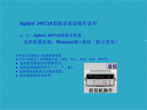
Agilent 34972A数据采集器操作说明
2)多路多功能复用器模块;
Agilent 34972A数据采集器操作说明
2)多路多功能复用器模块; 将导线连接到模块中如下图所示:
Agilent 34972A数据采集器操作说明
2)多路多功能复用器模块;
内部连接要求:
Agilent 34972A数据采集器操作说明
5.再按Measure键(表示确定并继续设置),再通过旋转旋扭,直到显示屏出现UNITS ℃ (度量单位为摄氏度)。 6.再按Measure键(表示确定并继续设置),再通过旋转旋扭,直到显示屏出现DISPLAY 0.1 ℃(显示精度0.1 ℃)。
7.再按Measure键,即可完成设置并退出。 其余各通道配置类似上述操作,具体步骤略。
Agilent ቤተ መጻሕፍቲ ባይዱ4972A数据采集器操作说明
1) Agilent 34972A数据采集器
选择配置参数:Measure键+旋钮(配合使用)
在所显示的通道上配置测量参数:
● 在显示的通道上选择测量功能(温度、电压、电阻、电流、频率等);
● 选择温度测量的传感器类型; ● 选择温度测量的单位(℃、℉、K); ● 选择测量量程或自动量程设置; ● 选择测量量程分辨率;
Agilent 34972A数据采集器操作说明
其他的例图
Agilent 34972A数据采集器操作说明
停止扫描
Agilent 34972A数据采集器操作说明
导出数据
Agilent 34972A数据采集器操作说明
导出的数据结果,仅供参考!
谢谢! 2013-1-18
3) Agilent BenchLink Data Logger 3软件使用过程:
安捷伦 Agilent Intuvo 9000 气相色谱仪 安全手册说明书
Agilent Intuvo 9000气相色谱仪安全手册声明© Agilent Technologies, Inc. 2017根据美国和国际版权法,未经 Agilent Technologies, Inc. 事先同意和书面许可,不得以任何形式、任何方式(包括存储为电子版、修改或翻译成外文)复制本手册的任何部分。
手册部件号G4580-97002版本第二版,2017 年 1月第一版,2016 年 9 月美国和中国印刷Agilent Technologies, Inc.2850 Centerville Road Wilmington, DE 19808-1610 USA安捷伦科技(上海)有限公司上海市浦东新区外高桥保税区英伦路 412 号联系电话:(800)820 3278担保说明本手册内容按“原样”提供,在将来的版本中如有更改,恕不另行通知。
此外,在适用法律允许的最大范围内,Agilent 对本手册以及此处包含的任何信息不作任何明示或暗示担保,包括但不仅限于适销性和针对某一特殊用途的适用性的暗示担保。
对于因提供、使用或执行本手册或此处包含的任何信息而产生的错误,或造成的偶然或必然的损失,Agilent 不承担任何责任。
如果安捷伦与用户签订了单独的书面协议,其中涉及本手册内容的担保条款与这些条款冲突,则以协议中的担保条款为准。
安全声明小心提示表示危险。
提醒您注意某个操作步骤、某项操作或类似问题,如果执行不当或未遵照提示操作,可能会损坏产品或丢失重要数据。
不要忽视小心提示,直到完全理解和符合所指出的条件。
“警告”声明表示存在危险。
提醒您注意某个操作步骤、某项操作或类似问题,如果执行不当或未遵照提示操作,可能会导致人身伤害或死亡。
除非已完全理解并符合所指出的条件,否则请不要忽视“警告”声明而继续进行操作。
Agilent Intuvo 9000 气相色谱仪安全手册简介重要安全警告 4氢气安全 6未燃尽的有害气体 8微电子捕获检测器 (µECD) 9安全与规范认证 11使用方法 16清洗 16通风橱 16回收产品 16简介重要安全警告在继续之前,使用 Agilent GC 时应时刻注意以下几个重要的安全注意事项。
安捷伦气相色谱仪系统简介

气相色谱系统7890 A 气相色谱系统6890N 气相色谱系统 6850 气相色谱仪6820 气相色谱系统7820 A 气相色谱仪(厂家推荐,全中文操作界面) 新!7000A 三重串联四级杆质谱系统 5975C 系列质谱系统 3000 微型气相色谱仪 1Agilent 7890A GC系统优异仪器性能 成就化学理想安捷伦7890A GC 为安捷伦公司40年领导GC 技术的历史谱写了激动人心的新篇章。
它为您提供了所需的一切,包括先进的分离能力, 强效的新功能和仪器智能化实时自监测,从而将您实验室的GC 和GC/MS 性能提升到一个新水平。
更快的柱箱降温速率和反吹功能,使您的分析时间更短, 样品的分析成本更低。
第五代电子气路控制 (EPC)和数字电路为压力设定和保留时间锁定(RTL)的精度 (0.001psi ) 设置了新的标准,使安捷伦7890GC 具有前所未有的可靠性。
特点多模式进样口包括分流/不分流, 升温,以及大容量进样器功能。
每个分流/不分流 (SSL 进样口)都采用了新的方便的扳转式顶盖设计,使您能在30秒内更换进样口衬管 - 无需特殊的工具或培训突破性的微板流路控制技术实现了柱箱内可靠的无泄漏连接,提高了工作效率和数据完整性,为复杂的GC 分析提供了通用、可靠的解决方案 。
低热容技术为极速分析周期和高效生产提供了迅速加热以及冷却的毛细管色谱柱Blos NPD 可提供更稳定的运行和更长的使用寿命。
安捷伦7693自动液相进样器具备对所有气相自动进样品的极快进样时间,附带对150-via 容器的同时注射, 并且加强了样品制备功能。
强大的、操作界面友好的GC软件简化了方法设置和系统操作,缩短了培训时间;您可选择正好符合您实验室需求的软件包。
其它气相软件包包括保留时间锁定和安捷伦远程监控与系统诊断软件能提升色谱分析能力。
在品质卓越的6890进样口, 检测器和GC柱箱上建立的分析方法, 您可以完全放心地将其转移到7890A GC上安捷伦提供了品种齐全的气相色谱分析仪附件的选件使您能够配置恰好满足您实验室目前需求2气相色谱系统6890N GC网络化使气相色谱仪更加易于使用安捷伦分析解决方案的推出正当其时,此方案可帮助您优化分析过程,满足当今商业环境中挑战性的需求。
安捷伦气相使用方法 PPT

顶空进样进样口设置
• 选择顶空进样时,选择后进样口。手动进 样时选择前进样口。并在Agrcp.exe中打开 后进样口。柱温、检测器、火焰、尾吹气 等相关程序。设置成功后点击开始按钮。
• 在联机中设置---在工具栏“仪器”中选择 设置Agilent 7820A仪器参数---将进样口改 为后进样口设置,进样口温度一般为200℃, 如采用火焰离子化检测器(FID)温度为 250℃。
柱箱模块-设置
• 柱箱设置—起始温度 • 如果为等温法,只设定��(初始值)速
率,保持分钟。运行分钟便可以。 • 如果为程序升温法,要起始温度,并设置
保持时间。升温速率等
大家有疑问的,可以询问和交流
可以互相讨论下,但要小声点
设置进样口
设置色谱柱
设置柱箱温度及进样时间
设置检测器温度
设置进样口,出样口及加热源
Agrcp.exe如图
Agrcp.exe
• 参数设置 • 1.如顶空进样在该工作站中选择“后进样”,
“后检测”,在后进样口将所有参数设置 为“打开”。 • 2.在后检测中,将所有参数设置为“打开”
• 控制模式为打开。
• 模式为一般为分流模式(分流比一般设置 10:1,可根据峰形进行调节)
• 色谱柱:要更改成自己所用的型号的色谱 柱,流速一般默认的为2ml/min,默认为恒定 流量,后运行流速仍为2ml/min。
安捷伦气相使用方法
顶空参数设置
• 加热箱温度即顶空瓶平衡温度水做溶剂一 般为70~85℃,平衡时间为30~45min,
• 其他溶剂平衡温度,根据样品的沸点选择 顶空温度。另外顶空平衡温度一般应低于 溶解供试品所用溶剂的沸点10℃以下。
• 定量环温度:一般高于平衡温度10℃ • 传输线温度一般高于定量环温度10~15℃ • 循环时间应大于平衡时间(包括后,点击应用按钮等待就绪。 • 另外在7697A顶空界面在“Seq’中设置序列,
安捷伦气相质谱

安捷伦气相质谱
安捷伦气相质谱仪是一款高性能的检测设备,主要用于对气体样品进行定性和定量分析。
该仪器采用先进的质谱技术,能够快速准确地检测出气体样品中的各种成分。
安捷伦气相质谱仪具有以下特点:
1.高灵敏度:采用高灵敏度的检测器,能够检测低浓度气体样品中的微量成
分。
2.快速分析:仪器的分析速度快,可以快速得出分析结果。
3.可靠性高:采用稳定可靠的技术,保证了分析结果的准确性。
4.自动化程度高:仪器具有自动化操作系统,能够实现自动进样、自动数据
分析等功能,减少了人工操作的误差。
5.应用范围广:可用于环保、化工、生物医药等多个领域的气体样品检测。
- 1、下载文档前请自行甄别文档内容的完整性,平台不提供额外的编辑、内容补充、找答案等附加服务。
- 2、"仅部分预览"的文档,不可在线预览部分如存在完整性等问题,可反馈申请退款(可完整预览的文档不适用该条件!)。
- 3、如文档侵犯您的权益,请联系客服反馈,我们会尽快为您处理(人工客服工作时间:9:00-18:30)。
Boot Boot
Tx
21
Waiting
案例:虚拟端口
RFIO 1 Switching 矢量信号分析 (Tx test) 矢量信号发生 (Rx test) RFIO 2 RFIO 3 RFIO 4
Rx Testing
Tx Testing Idle
Coordination & Control
DUT 1 DUT 2 DUT 3 DUT 4
Rx
DUT 1 DUT 2 DUT 3
Tx
Rx Tx Rx Tx Rx
DUT 4 DUT 5
Tx Rx Tx Rx Tx Rx
• 接收机测试时间(Rx test time) > 发射机测试时间(Tx test time)测 试效率提升明显
• 在FDD制式中,发射机和接收 机可以同时进行测试
DUT 6 DUT 7 DUT 8
Tx-DUT2
Rx-DUT2
time
Pipeline: 测试DUT1 Tx, 同时测试DUT2 Rx,然后互换
DUT1 RFI|O3 DUT2 RFIO|4
Boot-DUT1
Tx-DUT1 Rx-DUT2
Rx-DUT1 Tx-DUT2
Boot/DUT2
Time saved
18
案例: 多端口适配器 (MPA)
• 安捷伦的EXM无线综测仪如何帮助您解决现在和未 来的生产测试挑战
4
日程
市场动态,测试挑战
提高生产测试效率的技术手段
快速序列非信令测试(Fast sequenced non-signaling) 测试流程优化 一站多制式测试(Single insertion testing)
新技术挑战
LTE-A 载波聚合(Carrier Aggregation-CA) 802.11ac WLAN
高分辨率/高清媒体 的设备间分享,视频 流,云技术 • 更高的数据吞吐量和更宽的数据传输带 宽 • LTE-Advanced 载波聚合 无线终端设备迅猛增长 • 移动蜂窝终端设备预计在2020年将达到 240亿部 • 具备WLAN功能的设备以每年4亿部的数 量增长**
数据来源: *GSMA, ** IHS
高分辨率/高清媒体 的设备间分享,视频 流,云技术 • 更高的数据吞吐量和更宽的数据传输带 宽 • LTE-Advanced 载波聚合 无线终端设备迅猛增长 • 移动蜂窝终端设备预计在2020年将达到 240亿部 • 具备WLAN功能的设备以每年4亿部的数 量增长**
数据来源: *GSMA, ** IHS
测试设备 能力 芯片组 能力
非信令测试
基本射频测 试
Sequencer 高速序列 / SAMM*
基础非信令
非信令+序列模式
同步/序列 高速/ 多序列
非信令+快速序列模式
*SAMM--单次数据采集,多项测试技术
12
向更快的高速序列非信令测试演进
测试设备 能力 芯片组 能力
测试时间压缩
非信令测试
基本射频测 试
Sequencer 高速序列 / SAMM*
基础非信令
非信令+序列模式
同步/序列 高速/ 多序列
非信令+快速序列模式
*SAMM--单次数据采集,多项测试技术
13
序列(Sequence)的概念
14
加速从新产品导入到全面量产的过程
在非信令校准和综测模式中的两种应用模式
#1 在芯片厂商提供的测试程式中支持仪表的控制:
• 测试仪表在芯片厂商脚本中的支持 • 解决方案被芯片厂商和安捷伦验证 • 与最新的芯片型号和芯片技术同步
#2 将芯片的控制集成到安捷伦的测试软件中
• • • • 图形界面,可编程API 灵活数据库 校准和综测 时域分析
测试流程的优化
最小化仪表的空闲时间
更有效的利用测试仪表的方法:
• 乒乓测试(Ping Pong Test) • Pipeline • 多端口适配器 (MPA) • 虚拟端口(Virtual Port)
2
我们了解您生产测试的挑战
• 无线终端生产测试领域不断的挑战: 无线终端数量 和复杂度的增加,与此同时成本的降低 • 市场竞争压力: 以更低的生产成本制造更高品质产品
• 快速且充满信心地进入量产阶段
3
您从今天的演讲会中能学到什么?
• 如何在当今的生产测试环境中利用新技术进一步的 提升测试效率
• 最新的无线通信技术LTE-A载波聚合给生产测试带 来的挑战,如果从容应对 • 最近的802.11ac WLAN给生产测试带来的挑战,以 及如何克服这些挑战
收/发射频信号
芯片控制, 读取结果
10
向更快的高速序列非信令测试演进
测试设备 能力 芯片组 能力
非信令测试
基本射频测 试
Sequencer 高速序列 / SAMM*
基础非信令
非信令+序列模式
同步/序列 高速/ 多序列
非信令+快速序列模式
*SAMM--单次数据采集,多项测试技术
11
向更快的高速序列非信令测试演进
8
日程
市场动态,测试挑战
提高生产测试效率的技术手段
快速序列非信令测试(Fast sequenced non-signaling) 测试流程优化 一站多制式测试(Single insertion testing)
新技术挑战
LTE-A 载波聚合(Carrier Aggregation-CA) 802.11ac WLAN
DUT 1 DUT 2 DUT 3 DUT 4
Boot Boot Tx Rx Tx Rx Tx Rx Rx
Boot Boot
Tx
Waiting
23
一站式多制式测试
每个TRX连接一部智能手机, 在一个测试站完成所有制式的射频测试 (1 Tx/Rx &1 Rx for cellular, 1 Tx/Rx for WiCON, 1 Rx for GNSS)
Boot Boot Tx Rx Tx Rx Tx Rx Rx
Boot Boot
Tx
22
Rx Testing
案例:虚拟端口
RFIO 1 Switching 矢量信号分析 (Tx test) 矢量信号发生 (Rx test) RFIO 2 RFIO 3 RFIO 4
Tx Testing
Waiting
资源协调与控制
总结
灵活, 可扩展, 面向未来: EXM E6640A 无线综测仪
9
技术回顾: 非信令测试
传统的信令测试需要仪表模拟基站发送 OTA (Over-The-Air) 空中协议信号 非信令测试通过芯片驱动程式直接与终 端连接控制信号的收发和读取测试结果
测试脚本
测试脚本
驱动
信令综测仪
非信令综测仪
所有的终端 控制和测试 流程通过模 拟的BTS来 实现
27
演示 #1 (多被测件并行测试)
16
案例: 乒乓测试(Ping Pong)
同时连接8个双天线终端 (1 Tx/Rx, 1 Rx diversity)
Boot
被测件启动
Cal
校准
Tx
发射机测试
12
第一个TRX模块测试流程
Next DUT 1 DUT 2
Boot Cal Tx Rx RxD
Boot
Rx
接收机测试
RxD
辅天线测试
Unload / Load
总结
灵活, 可扩展, 面向未来: EXM E6640A 无线综测仪
5
无线终端设备生产制造
市场演进及测试挑战
市场演进
多天线,多模式的终端设备
• 移动终端多模多制式集成化 • 蜂窝网和WLAN的一致接入
测试挑战
测试多模终端设备
• GSM, W-CDMA, cdma2000®, TDSCDMA, LTE TDD/FDD, LTE-A • 蓝牙®, WLAN, GNSS (GPS) • MIMO, 载波聚合 更高性能的测试仪表 • 更高阶的调制: 256QAM • 更宽的带宽: 160 MHz • 更低的EVM值< –42 dBm 加速生产测试, 提高产线吞吐量 • 并行测试技术 • 快速进入量产阶段 • 增加直通率
高分辨率/高清媒体 的设备间分享,视频 流,云技术 • 更高的数据吞吐量和更宽的数据传输带 宽 • LTE-Advanced 载波聚合 无线终端设备迅猛增长 • 移动蜂窝终端设备预计在2020年将达到 240亿部 • 具备WLAN功能的设备以每年4亿部的数 量增长**
数据来源: *GSMA, ** IHS
具有4套TRX模块的EXM一站同步测试四部手机
每个被测件连接TRX 模块的RFIO1
被测件通过USB连接供电和连接自动化测试程式
26
演示 #1 (多被测件并行测试)
具有4套TRX模块的EXM一站同步测试四部手机
Test Automation Platform GSM 综测 WCDMA 综测
Power
GNSS
Rx Boot Cal Boot Cal
DUT 1
Next
24
测试仪表支持多种无线技术
Cellular
• LTE-Advanced, LTE FDD/TDD • HSPA+, W-CDMA • 1xEV-DO, cdma2000 • GSM/EDGE/EDGE Evo • TD-SCDMA • WiMAX • PHS
6
无线终端设备生产制造
市场演进及测试挑战
市场演进
多天线,多模式的终端设备
• 移动终端多模多制式集成化 • 蜂窝网和W
• GSM, W-CDMA, cdma2000®, TDSCDMA, LTE TDD/FDD, LTE-A • 蓝牙®, WLAN, GNSS (GPS) • MIMO, 载波聚合 更高性能的测试仪表 • 更高阶的调制: 256QAM • 更宽的带宽: 160 MHz • 更低的EVM值< –42 dBm 加速生产测试, 提高产线吞吐量 • 并行测试技术 • 快速进入量产阶段 • 增加直通率
