AD401M322RBB-5中文资料
AD401M84RCB-5中文资料
ASCEND Semiconductor 4Mx4 EDO Data sheetDescriptionThe device CMOS Dynamic RAM organized as 4,194,304 words x 4 bits with extended data out access mode. It is fabricated with an advanced submicron CMOS technology and designed to operate from a single 3.3V oniy power supply. Low voltage operation is more suitable to be used on battery backup, portable elec-tronic application. lt is packaged in JEDEC standard 26/24-pin plastic SOJ or TSOP(II).Features• Single 3.3V(%) only power supply • High speed t RAC acess time: 50/60ns • Low power dissipation- Active mode : 432/396 mW (Mas) - Standby mode: 0.54 mW (Mas)• Extended - data - out(EDO) page mode access • I/O level: CMOS level (Vcc = 3.3V)• 2048 refresh cycle in 32 ms(Std.) or 128 ms(S-version)• 4 refresh modesh: - RAS only refresh- CAS - before - RAS refresh - Hidden refresh - Self-refresh(S-version)10±Pin Name FunctionA0-A10Address inputs- Row address - Column address - Refresh address DQ1~DQ4Data-in / data-out RAS Row address strobe CAS Column address strobe WE Write enable OE Output enable Vcc Power (+ 3.3V)VssGroundVCC 1DQ12DQ23DQ34DQ45VCC6891011 NC 12 WE 13A0 A117 A218 A319VSS RAS CAS OE A8A7A6A5A4VSSAD404M42VSPin Description Pin Configuration21222324 2526151416 A1026/24-PIN 300mil Plastic SOJA9VCC 1DQ12DQ23DQ34DQ45VCC6891011 NC 12 WE 13A0 A117 A218 A319VSS RAS CAS OE A8A7 A6A5 A4VSSAD404M42VT212223242526151416 A1026/24-PIN 300mil Plastic TSOP (ll)A9A0-A10A0-A10A0-A10WECASNO. 2 CLOCK GENERATORCOLUMN ADDRESS BUFFERS (11)REFRESH CONTROLLERREFRESH COUNTERBUFFERS (11)ADDRESS ROW NO. 1 CLOCK GENERATORA0RASA1A2A3A4A5A6A7A8CONTROLLOGICDATA-IN BUFFERDATA-OUT BUFFEROEDQ1.DQ4.COLUMN DECODER2048SENSE AMPLIFIERSI/O GATING2048x42048x2048x4MEMORY ARRAY2048R O W D E C O D E RVcc VssBlock DiagramA9A10TRUTH TABLENotes: 1. EARLY WRITE only.FUNCTIONRASCAS WE OE ADDRESSESDQ SNotesROW COL STANDBY H X X X X High-Z READL L H L ROW COL Data-Out WRITE: (EARLY WRITE )L L L X ROW COL Data-lnREAD WRITE L L ROW COL Data-Out,Data-ln EDO-PAGE-MODE READ1st Cycle L H L ROW COL Data-Out 2nd CycleL H L n/a COL Data-Out EDO-PAGE MODE WRITE1st CycleL L X ROW COL Data-In 2nd Cycle L L Xn/a COL Data-InEDO-PAGE-MODEREAD-WRITE 1st Cycle L ROW COL Data-Out, Data-In 2nd Cycle L n/a COL Data-Out, Data-In HIDDEN REFRESHREAD L H L ROW COL Data-Out WRITEL L X ROW COL Data-In 1RAS-ONLY REFRESH L H X X ROW n/a High-Z CBR REFRESHLHXXXHigh-ZH X →H L →L H →H L →H L →H L →H L →H L →H L →L H →H L →H L →L H→L H L →→L H L→→H L→Absolute Maximum RatingsRecommended DC Operating ConditionsCapacitanceTa = 25°C, V CC = 3.3V%, f = 1MHz Note: 1. Capacitance measured with effective capacitance measuring method. 2. RAS, CAS = V IH to disable Dout.ParameterSymbol Value Unit Voltage on any pin relative to Vss V T -0.5 to + 4.6V Supply voltage relative to Vss V CC -0.5 to + 4.6V Short circuit output current I OUT 50mA Power dissipation P D 1.0WOperating temperature T OPT 0 to + 70°C Storage temperatureT STG-55 to + 125°CParameter/Condition Symbol3.3 Volt VersionUnitMinTyp MaxSupply VoltageV CC 3.0 3.33.6V Input High Voltage, all inputs V IH 2.0-V CC + 0.3V Input Low Voltage, all inputsV IL-0.3-0.8VParameterSymbol Typ Max Unit Note Input capacitance (Address)C I1 -5pF 1Input capacitance (RAS, CAS, OE, WE)C I2-7pF 1Output capacitance(Data-in, Data-out)C I/O-7pF1, 210±DC Characteristics :(T a = 0 to 70°C, V CC = + 3.3V%, V SS = 0V)Parameter Symbol Test Conditions AD404M42V Unit Notes-5-6Min Max Min MaxOperating current I CC1RAS cyclingCAS, cyclingt RC = min-120-110mA1, 2Standby Current LowpowerS-versionI CC2LVTTL interfaceRAS, CAS = V IHDout = High-Z-0.5-0.5mACMOS interfaceRAS, -0.2VDout = High-Z-0.15-0.15mAStandardpowerversionLVTTL interfaceRAS, CAS = V IHDout = High-Z-2-2mACMOS interfaceRAS,-0.2VDout = High-Z-0.5-0.5mARAS- only refresh current I CC3RAS cycling, CAS = V IHt RC = min-120-110mA1, 2 EDO page mode current I CC4t PC = min-90-80mA1, 3CAS- before- RAS refresh current I CC5t RC = minRAS, CAS cycling-120-110mA1, 2Self- refresh current (S-Version)I CC8 - 550 - 55010±CAS V CC≥CAS V CC≥t RASS100µs≥µADC Characteristics :(T a = 0 to 70°C , V CC = +3.3V %, V SS = 0V)Notes:1. I CC is specified as an average current. It depends on output loading condition and cycle rate when the device is selected. I CC max is specified at the output open condition.2. Address can be changed once or less while RAS = V IL .3. For I CC4, address can be changed once or less within one EDO page mode cycle time.Parameter Symbol Test Conditions AD404M42VUnitNotes-5-6Min MaxMin MaxInput leakage current I LI + 0.3V -55-55Output leakage current I LO + 0.3V Dout = Disable -55-55Output high Voltage V OH I OH = -2mA 2.4- 2.4-V Output low voltage V OLI OL = +2mA-0.4-0.4V10±0V Vin V CC ≤≤µA 0V Vout V CC ≤≤µAAC Characteristics(T a = 0 to + 70°C , V cc = 3.3V %, V ss = 0V) *1, *2, *3, *4Test conditions• Output load: one TTL Load and 100pF (V CC = 3.3V %)• Input timing reference levels:V IH = 2.0V, V IL = 0.8V (V CC = 3.3V %)• Output timing reference levels:V OH = 2.0V, V OL = 0.8V10±10±10±Read, Write, Read- Modify- Write and Refresh Cycles (Common Parameters)ParameterSymbol AD404M42V UnitNotes-5-6Min MaxMin MaxRandom read or write cycle time t RC 84-104-ns RAS precharge timet RP 30-40-ns CAS precharge time in normal mode t CPN 10-10-ns RAS pulse width t RAS 50100006010000ns 5CAS pulse width t CAS 8100001010000ns 6Row address setup time t ASR 0-0-ns Row address hold time t RAH 8-10-ns Column address setup time t ASC 0-0-ns 7Column address hold time t CAH 8-10-ns RAS to CAS delay timet RCD 12371445ns 8RAS to column address delay time t RAD 10251230ns 9Column address to RAS lead time t RAL 25-30-ns RAS hold time t RSH 8-10-ns CAS hold timet CSH 38-40-ns CAS to RAS precharge time t CRP 5-5-ns 10OE to Din delay time t OED 12-15-ns Transition time (rise and fall)t T 150150ns 11Refresh periodt REF -32-32ms Refresh period (S- Version)t REF -128-128ms CAS to output in Low- Z t CLZ 0-0-ns CAS delay time from Din t DZC 0-0-ns OE delay time from Dint DZO-0-nsRead CycleWrite Cycle Parameter SymbolAD404M42V Unit Notes-5-6Min Max Min MaxAccess time from RAS t RAC-50-60ns12 Access time from CAS t CAC-14-15ns13, 14 Access time from column address t AA-25-30ns14, 15 Access time from OE t OEA-12-15nsRead command setup time t RCS0-0-ns7 Read command hold time to CAS t RCH0-0-ns10, 16 Read command hold time to RAS t RRH0-0-ns16 Output buffer turn-off time t OFF012015ns17 Output buffer turn-off time from OE t OEZ012015ns17Parameter SymbolAD404M42V Unit Notes -5-6Min Max Min MaxWrite command setup time t WCS0-0-ns7, 18 Write command hold time t WCH8-10-nsWrite command pulse width t WP8-10-nsWrite command to RAS lead time t RWL13-15-nsWrite command to CAS lead time t CWL8-10-nsData-in setup time t DS0-0-ns19 Data-in hold time t DH8-10-ns19 WE to Data-in delay t WED10-10-nsRead- Modify- Write CycleRefresh Cycle Parameter SymbolAD404M42V Unit Notes-5-6Min Max Min MaxRead-modify- write cycle time t RWC108-133-nsRAS to WE delay time t RWD64-77-ns18 CAS to WE dealy time t CWD26-32-ns18 Column address to WE delay time t AWD39-47-ns18 OE hold time from WE t OEH8-10-nsParameter SymbolAD404M42VUnit Notes -5-6Min Max Min MaxCAS setup time (CBR refresh) t CSR5-5-nsCAS hold time (CBR refresh)t CHR8-10-ns10 RAS precharge to CAS hold time t RPC5-5-ns7 RAS pulse width (self refresh)t RASS100-100-RAS precharge time (self refresh)t RPS90-110-nsCAS hold time (CBR self refresh)t CHS-50--50-nsWE setup time t WSR0-0-nsWE hold time t WHR10-10-nsµsEDO Page Mode CycleEDO Page Mode Read Modify Write CycleParameterSymbol AD404M42VUnit Notes-5-6Min MaxMin MaxEDO page mode cycle timet PC 20-25-ns EDO page mode CAS precharge time t CP 10-10-ns EDO page mode RAS pulse width t RASP 5010560105ns 20Access time from CAS precharge t CPA -30-35ns 10, 14RAS hold time from CAS precharge t CPRH 30-35-ns OE high hold time from CAS high t OEHC 5-5-ns OE high pulse widtht OEP 10-10-ns Data output hold time after CAS low t COH 5-5-ns Output disable delay from WEt WHZ 310310ns WE pulse width for output disable whenCAS hight WPZ7-7-nsParameterSymbol AD404M42V Unit Notes -5-6Min MaxMin MaxEDO page mode read- modify- write cycle CAS precharge to WE delay timet CPW 45-55-ns 10EDO page mode read- modify- write cycle timet PRWC56-68-nsNotes :1. AC measurements assume t T = 2ns.2. An initial pause of 100 is required after power up, and it followed by a minimum of eightinitialization cycles (RAS - only refresh cycle or CAS - before - RAS refresh cycle). If the internal refresh counter is used, a minimun of eight CAS - before - RAS refresh cycles are required.3. In delayed write or read-modify-write cycles, OE must disable output buffer prior to applying data to the device.4. All the V CC and V SS pins shall be supplied with the same voltages.5. t RAS (min) = t RWD (min)+t RWL (min)+t T in read-modify-write cycle.6. t CAS (min) = t CWD (min)+t CWL (min)+t T in read-modify-write cycle.7. t ASC (min), t RCS (min), t WCS (min), and t RPC are determined by the falling edge of CAS .8. t RCD (max) is specified as a reference point only, and t RAC (max) can be met with the t RCD (max) limit.Otherwise, t RAC is controlled exclusively by t CAC if t RCD is greater than the specified t RCD (max) limit. 9. t RAD (max) is specified as a reference point only, and t RAC (max) can be met with the t RAD (max) limit.Otherwise, t RAC is controlled exclusively by t AA if t RAD is greater than the specified t RAD (max) limit. 10. t CRP , t CHR , t RCH , t CPA and t CPW are determined by the rising edge of CAS .11. V IH (min) and V IL (max) are reference levels for measuring timing or input signals. Therefore, transitiontime is measured between V IH and V IL .12. Assumes that t RCD tRCD (max) and t RAD t RAD (max). If t RCD or t RAD is greater than the maximum recommended value shown in this table, t RAC exceeds the value shown. 13. Assumes that (max) and (max).14. Access time is determined by the maximum of t AA , t CAC , t CPA . 15. Assumes that (max) and (max). 16. Either t RCH or t RRH must be satisfied for a read cycle.17. t OFF (max) and t OEZ (max) define the time at which the output achieves the open circuit condition (highimpedance). t OFF is determined by the later rising edge of RAS or CAS.18. t WCS , t RWD , t CWD , and t AWD are not restrictive operating parameters. They are included in the datasheet as electrical characteristics only. If (min), the cycle is an early write cycle and the data out will remain open circuit (high impedance) throughout the entire cycle. If (min),(min), (min) and (min), the cycle is a read-modify-write and the data output will contain data read from the selected cell. If neither of the above sets of conditions is satisfied, the condition of the data output (at access time) is indeterminate.19. These parameters are referenced to CAS separately in an early write cycle and to WE edge in adelayed write or a read-modify-write cycle.20. t RASP defines RAS pulse width in EDO page mode cycles.µs ≤≤t RCD t RCD ≥t RADt RAD ≤t RCD t RCD ≤t RAD t RAD ≥t WCS t WCS ≥t RWD t RWD ≥t CWDt CWD ≥t AWD t AWD ≥t CPW t CPW≥Timing Waveforms• Read Cyclet RC t RASt RPtCRPtCPNtRRHtRCHt OEZ t OFF tOEA tCACt AAtRACt CLZD OUTtRCS t ASR tRAH tASC tCAH tRAD t RALtCAStRSH tRCDt TtCSHRASCASADDRESSWEDQ1~DQ4Note : = don’t care OEt OFFRowColumn= Invalid Dout•Early Write CycletRC t RASt RPt WCHt DSt DHt WCS t RALtCAStRSH tRCDt TtCSHRASCASWEDQ1~DQ4tCRPtASRtRAH tASCtCAH ADDRESSColumnRowtCPND INtRADt RAL• Delayed Write CycletRC t RASt RPt RWL t RCSt CAStRSH tRCDt TtCSHRASCAStASR tRAH tCAHADDRESSColumnRow tASC D INDQ1~DQ4WEtCRPtCPNt DHt DSt OEHt OEDOEt DSOPENt WPt CWL• Read - Modify - Write CycletRWC t RASt RPtRWDt WPtRADtRWL tCAStCWL tRCDt TtCPNRASCASWEtCRP t ASRtRAHtASCtCAHADDRESS Column RowDQ1~DQ4t DHt DSOEtRCStAWD tCWD D INt OEDt OEHt OEZt OEA t CAC t RACt AADQ1~DQ4D OUTOPENtDZCtDZO• EDO Page Mode Read CycletRASPtCPRHt RCStCAStRSH tRCDt OEAtCSHRASCAStASRtRAHtCAHADDRESStCASWEtCRPt CPOEDQ1~DQ4OPENtOEPD OUT 1t PCt CPtCAStCPNtCRPtRADtCAHtASCt ASCtCAHt ASCt RAL Row Column 1t OEAt OEHCtRRH tRCHt RACt AAt AAt AA t CPA t CPA t OEZt OFFt OFFt CACt OEZt CAC t CACt COHD OUT NWE OE Column 2Column N Rowt RPD OUT 2• EDO Page Mode Early Write CycletRASPtRPt WCSt CAStRSH tRCDRASCAStASRtRAHtCAHADDRESStCASWEt CPDQ1~DQ4t PCt CPt CAStCPNtCRP tCAH tASCtASC tCAH tASC Row Column 1t DS WE Column 2Column Nt WCH t WCS t WCH t WCS t WCHt DH t DS t DH t DS t DHD IN 1D IN 2D IN Nt TtCSH• EDO Page Mode Read-Early-Write Cyclet RASPtCPRHt RCStCAStRSH tRCDt OEAtCSHRASCAStASRtRAHtCAHADDRESStCASWEtCRPt CPOEDQ1~DQ4OPENtWEDt PCt CPtCAStCPNtCRPtRADtRAHtASCt ASCtCAHt ASCt RAL Row Column 1tWCStRCHt RACt AAt AAt CPA t DHt WHZt CACt CACt COHWE OE Column 2Column N Rowt RPt CAL tWCHDataDoutput 2Data Input NDataDoutput 1t DStCSH• EDO Page Mode Read-Modify-Write Cyclet RASPt CPRHt RCStCASt WP RASCASt ASRtRAHtCAHADDRESSt CASWEtRCDCPDQ1~DQ4tPRWCt CPtCAStCRPtRADtCAHtASCt ASCtCAH tASC Row Column 1tRWLtRCSt OEDt DZOt CAC WE OEt RPt RAL D OUT 2D OUT ND OUT 1tTt Column NColumn 2Column 1tRWD tAWD tCWDtCWLtRCStCWDtAWD tCPW tCWL tCPW tAWD tCWDtCWL t OEDt OEDt OEHt OEHt OEHt CAC t CAC t OEA t AAt RACt OEZt OEAt AA t CPAt OEZt OEAt AA t CPAt OEZ t DSt DHt WP t DSt DHt WP t DSt DHOPENOPENOPEN D IN 1D IN ND IN 2DQ1~DQ4t DZCt DZOt DZCt DZCt DZO• Read Cycle with WE Controlled Disablet WPZt RCStCAStRCDt TtCSHRASCASt ASRtRAHtCAHADDRESSColumnRow tASCD DQ1~DQ4WEt OEZt DSt WHZOEt RCH t OEA t CACt AAt RACt CLZOUTtRADRASADDRESSt RC t CRPt ASRt RAHt Tt RPCROWt OFFCAS t RASt RPOPENt CRPDQ1~DQ4RASt CSRt WSRt RPt T t RPCt OFFCAS t RASt RPOPENt CRPDQ1~DQ4t RPCt CHRt RASt RPt RCt RCt CHRt CSRt WHRt WSRt WHRWECAS-Before-RAS Refresh CycleRASWEt RPCt OFFt CSRt CHSt WSRCASt RASS t RPSOPENDQ1~DQ4t WHRHigh lmpedance• Hidden Refresh Cyclet RPt RASRASt RCDt CRPADDRESSWEt CHRt CASt RSHt RAHt ASRt ASCt CAHt RAL ROW t RCHt OEZCASDQ1~DQ4t Tt RCSD t RASt RASt RPt RPt RC t RCt RCt RADt RRHt OFF t OFFt OEA t CACt AAt RACCOlumnOUTOE(READ)(REFRESH)(REFRESH)Ordering informationAD404M42VSA-5• AD• Ascend Memory Product • 40 • Device Type• 4M4 • Density and Organization • 2• Refresh Rate, 2: 2K Refresh • V• T: 5V, V: 3.3V• S • Package Type (S : SOJ, T : TSOP II)• A• Version• 5• Speed (5: 50 ns, 6: 60 ns)Part Number Access time PackageAD404M42VSA-5AD404M42VSA-6AD404M42VTA-5AD404M42VTA-650 ns 60 ns 50 ns 60 ns300mil 26/24-Pin Plastic SOJTSOP IIPackaging information • 300 mil, 26/24-Pin Plastic SOJ• 300 mil, 26/24-Pin TSOP II。
AD5320中文资料
a
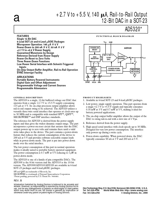
+2.7 V to +5.5 V, 140 A, Rail-to-Rail Output 12-Bit DAC in a SOT-23 AD5320*
FUNCTIONAL BLOCK DIAGRAM
VDD GND POWER-ON RESET
FEATURES Single 12-Bit DAC 6-Lead SOT-23 and 8-Lead SOIC Packages Micropower Operation: 140 A @ 5 V Power-Down to 200 nA @ 5 V, 50 nA @ 3 V +2.7 V to +5.5 V Power Supply Guaranteed Monotonic by Design Reference Derived from Power Supply Power-On-Reset to Zero Volts Three Power-Down Functions Low Power Serial Interface with Schmitt-Triggered Inputs On-Chip Output Buffer Amplifier, Rail-to-Rail Operation SYNC Interrupt Facility APPLICATIONS Portable Battery Powered Instruments Digital Gain and Offset Adjustment Programmable Voltage and Current Sources Programmable Attenuators
VDD 10
1/4 Scale to 3/4 Scale Change (400 Hex to C00 Hex). RL = 2 kΩ; 0 pF < CL < 200 pF. See Figure 16. RL = 2 kΩ; CL = 500 pF RL = ∞ RL = 2 k Ω 1 LSB Change Around Major Carry. See Figure 19.
mini smd 可编程数字AD型热释电红外传感器S22-P340R 使用说明书
MINI SMD 可编程数字AD 型热释电红外传感器Mini SMD Programmable AD Pyroelectric Infrared SensorsS22-P340R 使用说明书V1.2森霸传感科技股份有限公司Senba Sensing Technology Co.,Ltd.森霸传感科技股份有限公司1.企业及产品概况:1.1体系认证●ISO14001认证公司获得ISO14001认证,在遵守国家环保法的基础上,通过采取各种改进措施,实现企业可持续性发展。
●ISO 9001认证公司获得国际标准化机构(ISO)的品质保证标准-即“ISO 9001”的认证。
1.2关于欧盟ROHS指令ROHS指令:欧盟提出的“关于在电子电气设备中限制使用某些有害物质的指令2011/65/EC”,公司生产的所有产品均符合欧盟ROHS指令。
1.3产品型号及检测原理1.3.1产品规格型号:本产品为SMD 数字AD 型双元热释电红外传感器,产品型号为S22-P340R ,版本号为V1.2,若使用产品超出了产品列举的应用范围,请及时咨询产品应用或销售工程师。
1.3.2产品探测原理:传感器核心部件由热释电探测敏感元、红外滤光片和芯片IC三部分组成,其中探测敏感元为双元结构。
是一款用于低功耗运动检测的红外热释电传感器(PIR)。
利用MCU进行通信,当S22-P340R 进行连续运动传感时,MCU不需要激活,它只在检测到运动时才激活外部MCU。
运动检测结果通过输出中断信号发出。
运动检测的算法是可编程的,可以通过外部MCU配置来改变。
PIR信号在芯片上转换为一个14位的数字值,然后进入运动算法检测单元。
所有的信号处理都是数字化的,可支持运动检测结果输出和原始数据输出。
2.非商业用途说明森霸传感科技股份有限公司(以下简称森霸)免费授权用户非商业性使用本产品说明书,并为用户提供产品变更和咨询服务。
若要进行商业性的销售、复制、散发或其他商业活动,须事先获取森霸的书面授权和许可。
SAM3U中文手册(40-12位AD转换器 ADC12B)
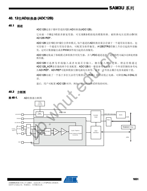
Conversion
Conversion
Read ADC12B_CDR0
Conversion
Read ADC12B_CDR1
警告: 转换期间,若相应通道被禁止或者禁止再允许,相应的数据和ADC12B_SR寄存器中 EOC位和OVRE位标志是不可预知的。
ADC12B可由外部软件、由内部定时计数器或PWM触发。
40.5.6 功耗调节
ADC12B的功耗可通过ADC12B_ACR寄存器的IBCTL位域调整,可灵活地根据转换 速度的要求来优化功耗和有效分辨率。
细节请参阅产品数据手册电气特性部分。
40.5.7 转换结果
当转换结束时,产生的12位数字值会存储于当前通道的ADC12B_CDR寄存器和公共的最后
转换数据寄存器ADC12B_LCDR中。
择。 ADC12B时钟范围从MCK/2到MCK/128,如果PRESCAL为零,ADC12B时钟取MCK/2;如 果PRESCAL 为63(0x3F),ADC12B时钟取MCK/128。 PRESCAL必须根据产品数据手册电 气特性部分所给出的参数来配置,以提供ADC12B时钟频率。
SAM3U 系列
40. 12位AD转换器 (ADC12B)
40.1 描述
ADC12B是基于循环管道的12位AD转换器(ADC12B)。
它内嵌一个 8选1模拟多路复用器,可实现 8条模拟线的模数转换。被转换电压范围由 0V到 AD12BVREF。
ADC12B支持10位和12位分辨率模式, 每个通道的AD转换结果会存储于一个通用寄存器内,也
40.5 功能描述
40.5.1 40.5.2 40.5.3
40.5.4
AD转换
ADC12B按照ADC12B的时钟来执行转换。 将一个模拟 量转换 为一个12的位数字值需要
四門控制器 RC5401 快速安裝指南说明书

面板LED 燈號 PCB 接點及Jumper跳線LED 燈號 顯示說明Jumper 跳線說明出廠設定 PWR 正常情況持續閃爍表CPU 有在正常運作 JP5 DI 外部或控制器內部供電切換 控制器內部供電 COM 未接卡機約每秒閃爍一次,接卡機閃爍速度變快JP6 設定繼電器(RELAY)是否由控制器供電控制器不供電 10M 當網路(LAN)通訊速率為10Mbps 時會亮燈 閉路(Close)表示由控制器供12VDC 電源100M 當網路(LAN)通訊速率為100Mbps 時會亮燈 JP7~JP12 繼電器(RELAY) NC 或NO 切換Normal Open DI1~DI8 當燈亮時表示該輸入接點導通JP15 韌體AP 是否啟用,開路(Open)表示啟用 韌體AP 啟用 RY1~RY6當燈亮時表示其對應之輸出接點繼電器作動後側板接點 接線說明接點及按鈕 接線說明C+ DI 外部電源輸入 (注意事項8) RESET 長按10秒控制器重置回出廠設定 DI1~DI4 出門按鈕接點對應1~4門點 預設IP 位址:10.0.50.100 DI5~DI8 火災發報接點對應1~4門點 COM RS485(2線/4線)串接讀卡機使用 G控制器共地接點 (注意事項8) LAN RJ45網路接線RY1+~RY4+ 外部電源輸入接點對應1~4門的電鎖使用DC JACK 控制器電源輸入(12VDC) RY1-~RY4-電源輸出至1~4門的電鎖使用PWR控制器電源輸入(12VDC)注意事項1. 控制器請使用12VDC 供電,允許的輸入電壓為9VDC~13VDC;控制器輸入電源,DC JACK 與端子接點(PWR)兩者擇一2. 控制器若斷電超過24小時,系統時鐘需重新設定3. 控制器韌體版本必須與讀卡機相符方可正常使用;版本ATOP 4Door ATT 是Atop 讀卡機使用,ATOP 4Door SOYAL 是Soyal 讀卡機使用4. 讀卡機RS-485 ID1~ID4為進入卡機,ID5~ID8為出門卡機5. 讀卡機的通訊線路建議使用22AWG 具Shielding 防護之雙絞線材;以一進一出方式串接卡機6. 電鎖的電源與控制器的電源分開供電,避免電鎖作動瞬間影響控制器7. 訊號傳輸線與電源線建議分開配管,避免訊號干擾8.當JP5切換使用"C+"外部電源時,勿使用"G"接點作為共地接點,應使用DI 外部電源之地電壓當迴路地控制器與HID卡機、AR1200韋根轉換器、電鎖建議接線圖控制器與卡機、電鎖建議接線圖電鎖由卡機控制接線圖控制器進出管制接線圖注意事項1. 電鎖及出門按鈕由控制器直接控制,安全性較高2. 若為節省佈線,可將電鎖及出門按鈕由轉換器控制3. 電鎖繼電器的NC/NO依電鎖型式決定,一般的陽極鎖或磁力鎖為NC4. 電鎖的電源建議獨立供電5. 電鎖建議外加一個反向二級體(1N4001)保護電路注意事項1. 進讀卡機的RS-485 ID為1~4,出讀卡機的RS-485 ID為5~82. 電鎖及出門按鈕由控制器直接控制,安全性較高3. 若為節省佈線,可將電鎖及出門按鈕由進讀卡機控制4. 電鎖繼電器的NC/NO依電鎖型式決定,一般的陽極鎖或磁力鎖為NC5. NC/NO使用控制器PCB之JUMPER JP7~JP10跳線6. 電鎖的電源建議獨立供電7. 電鎖建議外加一個反向二級體(1N4001)保護電路RS485 D+RS485 D-出門按鈕V+DI1DI COMVIN+NC1COM1To Vout+To Vout-控制器Wiegand注意事項1. 電鎖及出門按鈕由卡機控制,可節省佈線,但安全性較低2. 電鎖繼電器的NC/NO依電鎖型式決定,一般的陽極鎖或磁力鎖為NC3. 電鎖的電源建議獨立供電4. 電鎖建議外加一個反向二級體(1N4001)保護電路注意事項1. 電鎖及出門按鈕由控制器直接控制,安全性較高2. 電鎖繼電器的NC/NO依電鎖型式決定,一般的陽極鎖或磁力鎖為NC3. NC/NO使用控制器PCB之JUMPER JP7~JP10跳線4. 電鎖的電源建議獨立供電5. 電鎖建議外加一個反向二級體(1N4001)保護電路磁簧DI_GDIPCB跳線控制器出門按鈕警報器V+外部電源V-Pin6PCB跳線參見注意事項Pin7Pin8Pin1Pin2GND控制器電源供應器(For 控制器&卡機)出門按鈕V-RS485 D+DI_GDIGND V+(12V)電源供應器(For 電鎖)GNDID=1控制器警報器磁簧外部電源V+V+Pin5Pin6Pin9Pin7。
AD4001 AD4005 数据手册说明书

16位、2 MSPS/1 MSPS 、精密差分SAR ADC数据手册AD4001/AD4005Rev. ADocument FeedbackInformation furnished by Analog Devices is believed to be accurate and reliable. However, no responsibility is assumed by Analog Devices for its use, nor for any infringements of patents or other rights of third parties that may result from its use. Specifications subject to change without notice. No license is granted by implication or otherwise under any patent or patent rights of Analog Devices. Trademarks andregistered trademarks are the property of their respective owners.One Technology Way, P .O. Box 9106, Norwood, MA 02062-9106, U.S.A.Tel: 781.329.4700 ©2017 Analog Devices, Inc. All rights reserved. Technical Support /cnADI 中文版数据手册是英文版数据手册的译文,敬请谅解翻译中可能存在的语言组织或翻译错误,ADI 不对翻译中存在的差异或由此产生的错误负责。
如需确认任何词语的准确性,请参考ADI 提供的最产品特性吞吐速率:2 MSPS/1 MSPS 可选INL :±0.4 LSB (最大值) 保证16位无失码 低功耗9.5 mW (2 MSPS),4.9 mW (1 MSPS)(仅VDD ) 80 μW (10 kSPS),16 mW (2 MSPS)(总计)SNR :典型值96.2 dB (1 kHz, V REF = 5 V);典型值95.5 dB (100 kHz) THD :典型值−123 dB (1 kHz, V REF = 5 V);典型值−99 dB (100 kHz) 易用特性可降低系统功耗和复杂性 输入过压箝位电路减少了非线性输入电荷反冲 高阻态模式 长采集阶段 输入范围压缩快速转换时间支持很低的SPI 时钟速率 SPI 可编程模式、读/写能力、状态字 差分模拟输入范围:±V REF0 V 至V REF (V REF 在2.4 V 至5.1 V 之间)单电源工作:1.8 V ,逻辑接口电压:1.71 V 至5.5 V SAR 架构:无延迟/流水线延迟,首次转换有效 精确的首次转换保证工作:−40°C 至+125°CSPI/QSPI/MICROWIRE/DSP 兼容串行接口以菊花链形式连接多个ADC ,并能提供繁忙指示10引脚封装:3 mm × 3 mm LFCSP 、3 mm × 4.90 mm MSOP 封装应用自动测试设备 机器自动化 医疗设备 电池供电设备 精密数据采集系统概述AD4001/AD4005是低噪声、低功耗、高速、16位精密逐次逼近型寄存器(SAR)模数转换器(ADC)。
PDC401NRV0R规格书(南京丙鼎)-12页word资料
技术文件技术文件名称:PDC401NRV0R技术文件编号:JS00429A版本:A/0共 13 页(包括封面)拟制审核标准化批准南京丙鼎电子有限公司1.显示指标22.极限参数23.直流特性24.光电特性35.管脚连接36.编码表37.外观要求38.质量保证99.LCD模块使用注意事项111.显示指标显示像素:4个七段8字+4个圆点+1个冒号可视区域:36.8(W)×16.3(H)毫米外型尺寸:最大60(W)×35.5(H)×10(T)毫米LCD类型:TN显示模式:反射式、正显示视角:6:00点钟控制/驱动芯片:KS0065温度范围:工作-30℃~+70℃存储- 40℃~+75℃模块工作电压:5V.背光源工作电压:5V2.极限参数2.1电压及温度极限参数注意(1)T a= 0°C :最大50Hr(2)T a≤40°C :最大90%RHT a≥40°C :绝对湿度必须低于40°C、90%RH下的湿度。
3.直流特性4.光电特性4.1 TN屏体光电特性5.管脚连接6.编码表7.外观要求7.1检查项目7.2 判定标准8.质量保证8.1 测试条件8.1.1 温度和湿度(环境温度)温度:20±5℃湿度:65±5%RH8.1.2 测试频率单循环注意1:常温下恢复4小时注意2:观察时无露水凝结注意3:各项试验后,在规定测试条件下模块能正常工作。
8.1.4 试验条件低温运行:-30℃持续时间:4h高温运行:+70℃持续时间:4h高温存贮:+75℃持续时间:4h恢复时间:2h低温存贮:-40℃持续时间:4h恢复时间:2h恒定湿热:+35℃湿度:93%+2%/-3%持续时间48h高低温冲击:跌落:整机做跌落试验,按照整机跌落试验的条件进行。
8.2 试验内容LCD测试:测试时,笔划有无多缺、颜色是否均匀、对比度是否良好。
环境测试:如果测试条件不允许,可以考虑将以下所有“箱内在线测试”改为“取出后立即测试”。
无源停电报警器

无源停电报警器摘要这里介绍的停电报警器不需要备用电池,当220V交流电网停电时,它就会发出长约5min急促的“嘟-嘟-”报警声。
它是根据光电耦合器4N25的性能,来改变具有振荡器功能与非门CD4011的工作状态,当起振时陶瓷片B就会发出报警声音。
它可用于装有自动打铃装置学校的传达室中,知道停电后,可采用人工打铃保证学校作息时间不受影响。
关键字:关键字:无源报警器、光电耦合器4N25、CD4011目录第一章前言 (1)第二章电路原理及主要功能模块 (2)2.1电路原理图及其工作原理分析 (2)2.2振荡电路模块 (3)2.3整流电路模块 (5)2.3光电耦合电路模块 (7)第三章电路集成块和集成芯片基本功能介绍 (9)3.1二输入端四与非门CD4011集成电路 (9)3.2光电耦合器4N25 (11)第四章元器件选择及其分析介绍 (14)4.1电容 (14)4.2电阻 (15)4.3二极管 (16)4.4压电陶瓷片 (18)第五章电路装置、调试及其故障分析 (19)5.1 元器件检测 (19)5.2 面包板调试其电路功能 (19)5.3 印刷电路板的规划及其元器件的安装 (19)5.4 手工焊接 (20)5.5电路的调试、故障分析及其结果 (21)第六章结束语 (22)6.1论文总结 (22)6.2工作展望 (22)参考文献、资料索引 (23)致谢 (24)第一章前言在电子科学技术高速发展的今天,电子产品越来越多的应用在我们的日常生活中,像日常我们工作所用的电脑、手机等等,这些高科技产品给我们带来了极大的方便,这要归功于科学技术的高度发达。
如今,日常生活也越来越走向电子化。
无源停电报警器是我们所要做的毕业设计课题。
它的电路主要包括振荡电路、整流电路和光电耦合电路三大部分。
无源停电报警器涉及到《模拟电子技术》、《数字电子技术》中的相关知识。
特别是对一些电路的分析都涉及到《模拟电子技术》中所讲到的知识以及面对电路时的分析方法、思路。
施耐德宝光微机保护产品选型手册说明书
Schneider Baoguang关于施耐德宝光施耐德(陕西)宝光电器有限公司(简称SSBEA或施耐德宝光)是施耐德电气有限公司与陕西宝光集团有限公司共同组建的一家专业从事中、系统及相关产品研发、生产和销售的中外合资企业。
高新科技园区。
在世界五百强企业与中国中压电器龙头企业的通力合作下,作为国内中压行业著名的“宝光”品牌真空断路器的唯一合法生产商,施耐德宝光秉承精益生产科学理念,凭借品质过硬、安全可靠的全系列高品质产品和覆盖用户全生命周期的完善服务,帮助用户实现卓越的生产运营绩效和市场竞争力,用品质的“不妥协”实现可持续发展之道。
我们致力于将施耐德宝光打造成为中国卓越和高效的中压断路器和系统的制造平台,依托自身的专业优势,为广大用户和合作伙伴提供领先的总成本和长期全面的安心保障。
目录V5系列新一代微机保护测控装置 (1)产品概述 (1)产品特点 (2)型号及功能说明 (3)保护功能 (4)测控功能 (6)技术参数 (7)典型接线图 (8)外形尺寸及面板开孔尺寸 (11)V5订货选型表 (12)V3系列微机保护测控装置 (13)产品概述 (13)产品特点 (14)型号及功能说明 (15)保护功能 (16)测控功能 (17)技术参数 (18)典型接线图 (19)外形尺寸及面板开孔尺寸 (21)V3订货选型表 (22)V3U微机综合保护装置 (23)产品概述 (23)型号及功能说明 (24)保护功能 (25)测控功能 (26)技术参数 (27)外形尺寸图/典型接线图 (28)后台系统 (29)系统总体结构 (30)V5系列新一代微机保护测控装置是一种用于测量、控制、保护、通讯一体化的智能设备,产品主要用于工业及能源领域对线路、变压器、电动机及电容器的保护测控。
此产品外观时尚、结构精巧、大屏幕液晶显示,图形化中文菜单,四位方向导航盘,操作快捷方便。
内部基于SOC芯片软件方案,32位处理器,并根据硬件进行深度改良优化的嵌入式操作系统,使CPU运行效率更高。
APDA03-41MBWA资料

Recommended Soldering Pattern (Units : mm)
SPEC NO: DSAB2967 APPROVED: J.Lu
REV NO: V.3 CHECKED:Joe Lee
DATE:DEC/07/2002 DRAWN:Y.H.LI
PAGE: 4 OF 5
元器件交易网
SPEC NO: DSAB2967 APPROVED: J.Lu
REV NO: V.3 CHECKED:Joe Lee
DATE:DEC/07/2002 DRAWN:Y.H.LI
PAGE: 1 OF 5
元器件交易网
Selection Guide
P ar t N o . Dic e L en s Ty p e Iv (u c d ) @ 10m A Min . APDA03-41MBWA BLUE(GaN) WHITE DIFFUSED 1200 Ty p . 5000 Common Anode,Rt. Hand Decimal D es c r i p t i o n
元器件交易网SURΒιβλιοθήκη ACE MOUNT DISPLAY
APDA03-41MBWA BLUE
Features
!0.3INCH
Description
The Blue source color devices are made with GaN on SiC Light Emitting Diode. Static electricity and surge damage the LEDS. It is recommended to use a wrist band or anti-electrostatic glove when handling the LEDs. All devices, equipment and machinery must be electrically grounded.
PMC-851X综合保护测控装置用户说明书_V1.5_131014
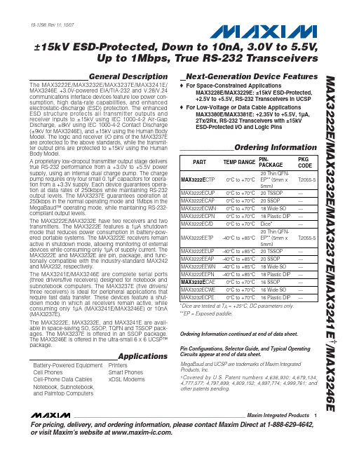
MAX3222EEUP中文资料
Battery-Powered Equipment Cell Phones Cell-Phone Data Cables Notebook, Subnotebook, and Palmtop Computers
Applications
Printers Smart Phones xDSL Modems
_______________Ordering Information
PART
TEMP RANGE
PINPACKAGE
PKG CODE
MAX3222ECTP MAX3222ECUP
0°C to +70°C 0°C to +70°C
20 Thin QFNEP** (5mm x 5mm) 20 TSSOP
♦ For Low-Voltage or Data Cable Applications MAX3380E/MAX3381E: +2.35V to +5.5V, 1µA, 2Tx/2Rx, RS-232 Transceivers with ±15kV ESD-Protected I/O and Logic Pins
MAX3222EEPN -40°C to +85°C 18 Plastic DIP —
MAX3232ECAE 0°C to +70°C 16 SSOP
—
MAX3232ECWE 0°C to +70°C 16 Wide SO —
MAX3232ECPE 0°C to +70°C 16 Plastic DIP —
A proprietary low-dropout transmitter output stage delivers true RS-232 performance from a +3.0V to +5.5V power supply, using an internal dual charge pump. The charge pump requires only four small 0.1µF capacitors for operation from a +3.3V supply. Each device guarantees operation at data rates of 250kbps while maintaining RS-232 output levels. The MAX3237E guarantees operation at 250kbps in the normal operating mode and 1Mbps in the MegaBaud™ operating mode, while maintaining RS-232compliant output levels.
ADI电路笔记 CN-0359说明书

电路笔记CN-0359Circuits from the Lab® reference designs are engineered and tested for quick and easy system integration to help solve today’s analog, mixed-signal, and RF design challenges. For more information and/or support, visit /CN0359.连接/参考器件AD825310 MHz、20 V/μs、G = 1、10、100、1000、i CMOS可编程增益仪表放大器ADuCM360集成双通道Σ-Δ型ADC和ARM Cortex-M3的低功耗精密模拟微控制器ADA4627-1 30 V、高速、低噪声、低偏置电流JFET运算放大器AD8542CMOS轨到轨通用放大器ADA4000-1 低成本、精密JFET输入运算放大器ADP2300 1.2 A、20 V、700 kHz/1.4 MHz异步降压型稳压器ADA4638-1 30 V、零漂移、轨到轨输出精密放大器ADP1613 650 kHz/1.3 MHz升压PWM DC-DC开关转换器ADA4528-2 精密、超低噪声、RRIO、双通道、零漂移运算放大器ADG1211低电容、低电荷注入、±15 V/+12 V iCMOS四通道单刀单掷开关ADA4077-2 4 MHz、7 nV/√Hz、低失调和漂移、高精度放大器ADG1419 2.1 Ω导通电阻、±15 V/+12 V/±5 V、iCMOS单刀双掷开关AD8592 CMOS、单电源、轨到轨输入/输出运算放大器,具有关断功能ADM3483 3.3 V限摆率、半双工、RS-485/RS-422收发器全自动高性能电导率测量系统Rev. 0Circuits from the Lab® reference designs from Analog Devices have been designed and built by AnalogDevices engineers. Standard engineering practices have been employed in the design andconstruction of each circuit, and their function and performance have been tested and veri ed in a labenvironment at room temperature. However, you are solely responsible for testing the circuit and determining its suitability and applicability for your use and application. Accordingly, in no event shall Analog Devices be liable for direct, indirect, special, incidental, consequential or punitive damages due to any cause whatsoever connected to the use of any Circuits from the Lab circuits. (Continued on last page)One Technology Way, P.O. Box 9106, Norwood, MA 02062-9106, U.S.A. Tel: 781.329.4700 Fax: 781.461.3113 ©2015 Analog Devices, Inc. All rights reserved.评估和设计支持电路评估板CN-0359电路评估板(EVAL-CN0359-EB1Z)设计和集成文件原理图、源代码、布局文件、物料清单电路功能与优势图1中的电路是一个完全独立自足、微处理器控制的高精度电导率测量系统,适用于测量液体的离子含量、水质分析、工业质量控制以及化学分析。
rc522中文资料_数据手册_参数

MFRC522_34本文档提供的所有信息均受法律免责声明保护. ?恩智浦BV 2010.保留所有权利.产品数据表上市 3.4版 - 2010年3月5日 112134 31的96恩智浦半导体 MFRC522非接触式读卡器IC 8.6节电模式 8.6.1硬盘掉电当引脚NRSTPD为低电平时,MFRC522硬件掉电被 使能.这将关闭所有内部电流包括振荡器的汇.所有数字输入缓冲器都与输入引脚分开内部钳位(引脚NRSTPD除外).输出引脚在高电 平或低电平时被冻结低级. 8.6.2软关断模式在COMMANDREG寄存器之后立即进入软休眠模式 POWERDOWN位被设置为逻辑1.所有 内部电流吸收器都被关闭,包括振荡器缓冲.但是,MFRC522数字输入缓冲器并未与输入引脚分开并保持其功能.数字输出引脚不会改 变它们的状态.在软件关断期间,所有寄存器值,FIFO缓冲区内容和配置保持其当前内容.将POWERDOWN位设置为逻辑0后,需要 1024个时钟直到软关断模式退出由POWERDOWN位指示.将其设置为逻辑0不会立即生效清除它.软关断模式时,它由MFRC522自动清 零退出.备注:如果使用内部振荡器,则必须考虑它是由哪个振荡器提供的 引脚AVDD,并且它需要一定的时间(T OSC )MFRC522 直到振荡器稳定并且时钟周期可以被内部逻辑检测到.首先推荐用于串行UART将值55H发送到MFRC522.振荡器必须稳定才能进一步 访问寄存器.为确保这一点,对地址0执行读取访问,直到MFRC522回答上次读取命令,地址为0的寄存器内容.这表示 MFRC522已准备 就绪. 8.6.3发射机掉电模式发射机掉电模式由此关闭内部天线驱动器,MFRC522关闭射频场.变送器掉电模式通过设置 TXCONTROLREG寄存器的TX1RFEN位或TX2RFEN位置为逻辑0. 8.7振荡器电路图22.石英晶体连接 产品数据表上市 3.4版 - 2010年3月5日 112134 25的96恩智浦半导体 MFRC522非接触式读卡器IC 8.2.3串行数据交换 MFRC522实现了两个 主要模块.数字模块包含状态机器,编码器/解码器逻辑.模拟模块包含调制器和天线驱动器,接收器和放大器. MFRC522它们之间的接 口是可能的两个模块需要配置,以便将接口信号路由到引脚MFIN和 MFOUT.该拓扑结构允许将MFRC522的模拟模块连接到数字模块 的另一个设备.串行信号开关由TXSELREG和RXSELREG寄存器控制.图20显示了用于P-DRIVER TX1和TX2的串行数据开关. 8.2.4 MFIN 和MFOUT接口支持 MFRC522分为数字电路模块和模拟电路模块.数字块包含状态机,编码器和解码器逻辑等.模拟块包含调制器和天 线驱动器,接收器和放大器.界面在这两个模块之间可以进行配置,以便可以路由接口信号到引脚MFIN和MFOUT;请参阅第26页的图 21.该配置已实施使用TXSELREG寄存器的MFOUTSEL [3:0]和DRIVERSEL [1:0]位和RXSELREG寄存器 UARTSEL [1:0]位.这种拓扑 结构允许模拟模块的某些部分连接到数字模块另一个设备. TXSELREG寄存器中的开关MFOUTSEL可用于测量MIFARE和 ISO / IEC14443 A相关信号.这在设计阶段尤为重要或用于测试目的,因为MFRC522能够检查发送和接收的数据. MFIN和MFOUT引脚的重要 用途可以在有源天线概念中找到.外部有源天线电路可以连接到MFRC522的数字模块.必须配置开关MFOUTSEL,以便发送内部米勒编 码信号引脚MFOUT(MFOUTSEL = 100B). UARTSEL [1:0]必须配置为接收一个具有来自MFIN引脚的子载波的曼彻斯特信号
更多难得资料请到江南家电维修论坛下载!

一:机芯介绍机芯功能介绍在功能上可以实现模拟PAL制式电视信号的60HZ逐行、100HZ两种扫描模式,高清信号可以显示1080P/60,1080I/60,1080I/50,720P/60和逐行DVD 信号(图像)。
VGA方式支持640*480/60 800*600/60 1024*768/60三种模式。
产品外观介绍HDP2433为33系列外观二、机芯概述HDP2433机芯是采用华亚公司的芯片HTV180单芯片的视频处理方案,HTV180集成了ADC ,解码器,OSD 产生器,行场频转换处理芯片以及CPU 。
采用了东芝的TB1306,其功能是预视放、行场激励输出、EW 输出、EHT 、ABL 。
解码板板号是RSAG7.820.947A 。
主板是RSAG7.820.983,主板伴音切换芯片采用HEF4052BP ,伴音功放电路为ST 的TFA9842AJ ,其功能是3路声音输入,总线用两个I/O 口控制切换实现一路输出到伴音功放芯片TFA9842AJ ,总线用一路PWM 控制TFA9842AJ 的VOLUME 脚(7脚)实现音量控制。
视放板板号RSAG7.820.954,采用美国国家半导体的LM2451视放电路。
更多难得资料请到江南家电维修论坛下载!三、原理说明电源部分1:电源框图电源部分工作原理介绍本电源控制芯片采用FAIRCHILD公司的开关电源集成电路FSCQ1265,这是一种内置功率MOSFET和控制器的回扫型开关电源集成电路,且具有过流、过压、过热保护电路。
交流220V经过整流、稳压后提供给开关变压器T501,开关变压器共有5路输出:+B(130V)、+15V、+17V和+8V,10V。
+17V输出开关变压器16脚输出经整流后给N601(TFA9842AJ)第9脚提供电压+10V输出:通过变压器14脚整流输出10V给7805给解码板CPU供电5V-1,给光藕提供参考电压。
+8V输出:通过变压器18脚整流输出8V给3852调制5V 给解码板供电5V-2。
AD420中文资料

AD420中文资料摘要:AD420是具有灵活串行数字接口的16住数模转换器,它带有SPI和Microwire总线接口,使用方便、性价比高。
介绍了AD420的引脚功能、电气特性,阐述了AD420与MSP430的接口技术,并给出了在MSP430控制下的实际应用电路及程序。
关键词:AD420;D/A转换;MSP430;电流环1 概述AD420是ADI公司生产的高精度、低功耗全数字电流环输出转换器。
AD420的输出信号可以是电流信号,也可以是电压信号。
其中电流信号的输出范围为4mA~20mA,0mA~20mA或0mA~24mA,具体可通过引脚RANGE SELECTl,RANGE SELECT2进行配置。
当需要输出电压信号时,它也能从一个隔离引脚提供电压输出,这时需外接一个缓冲放大器,可输出0V~5V,0V~10V,±5V 或±10V电压。
AD420具有灵活的串行数字接口(最大速率可达3.3 Mb/s),使用方便、性价比高、抑制干扰能力强,非常适合用于高精度远程控制系统。
AD420与单片机的接口方式有2种:3线制和异步制。
单片机系统通过AD420可实现连续的模拟量输出。
其主要特点如下:宽泛的电源电压范围为12 V~32 V,输出电压范围为0V~-2.5 V;带有3线模式的SPI或Microwire接口,可采集连续的模拟输入信号,采用异步模式时仅需少量的信号线;数据输出引脚可将多个AD420器件连接成菊链型;上电初始化时,其输出最小值为0 mA,4 mA或O V;具有异步清零引脚,可将输出复位至最小值(0mA、4 mA或0V);BOOST引脚可连接一个外部晶体管来吸收回路电流,降低功耗;只需外接少量的外部器件,就能达到较高的精度。
AD420采用24引脚SOIC和PDIP封装,表1是其引脚功能说明。
2 工作原理在AD420中,二阶调节器用于保持最小死区。
从调节器发出的单字节流控制开关电流源,两个连续的电阻电容装置进行过滤。
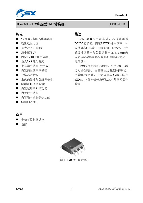
LPD3201B中文资料
35
VIN=60V,VOUT=15V,IOUT=0.1~0.2A
30
VIN=72V,VOUT=15V,IOUT=0.1~0.2A
25
20
0.10
0.12
0.14
0.16
0.18
0.20
Ouput current(A)
图 9. LPD3201B 系统效率曲线
Rev 1.0
7
深圳市硕芯科技有限公司
0.4A 150KHz 80V降压型DC-DC转换器 系统典型应用(VOUT=5V/0.4A)
9
深圳市硕芯科技有限公司
ŋ
效率
Vin=36V ,Vout=15V Iout=0.2A
ŋ
效率
Vin=48V ,Vout=15V Iout=0.2A
ŋ
效率
Vin=60V ,Vout=15V Iout=0.2A
最小值
1.225 -
典型值
1.25 86 81 75
最大值 单位
1.275
-
%
-
%
-
%
电气特性(直流参数)
Vin = 48V,GND=0V,Vin与GND之间并联33uF/100V电容;Iout=200mA,Ta = 25℃;其 他任意,除非特别说明。
Input voltage(V)
图 6.最大输出电流(VOUT=12V)
Recommend output current safe work range
0.30
0.25
VOUT=15V
Output current(A)
0.20
0.15
0.10 16 20 24 28 32 36 40 44 48 52 56 60 64 68 72 76 80
- 1、下载文档前请自行甄别文档内容的完整性,平台不提供额外的编辑、内容补充、找答案等附加服务。
- 2、"仅部分预览"的文档,不可在线预览部分如存在完整性等问题,可反馈申请退款(可完整预览的文档不适用该条件!)。
- 3、如文档侵犯您的权益,请联系客服反馈,我们会尽快为您处理(人工客服工作时间:9:00-18:30)。
ASCEND Semiconductor 4Mx4 EDO Data sheetDescriptionThe device CMOS Dynamic RAM organized as 4,194,304 words x 4 bits with extended data out access mode. It is fabricated with an advanced submicron CMOS technology and designed to operate from a single 3.3V oniy power supply. Low voltage operation is more suitable to be used on battery backup, portable elec-tronic application. lt is packaged in JEDEC standard 26/24-pin plastic SOJ or TSOP(II).Features• Single 3.3V(%) only power supply • High speed t RAC acess time: 50/60ns • Low power dissipation- Active mode : 432/396 mW (Mas) - Standby mode: 0.54 mW (Mas)• Extended - data - out(EDO) page mode access • I/O level: CMOS level (Vcc = 3.3V)• 2048 refresh cycle in 32 ms(Std.) or 128 ms(S-version)• 4 refresh modesh: - RAS only refresh- CAS - before - RAS refresh - Hidden refresh - Self-refresh(S-version)10±Pin Name FunctionA0-A10Address inputs- Row address - Column address - Refresh address DQ1~DQ4Data-in / data-out RAS Row address strobe CAS Column address strobe WE Write enable OE Output enable Vcc Power (+ 3.3V)VssGroundVCC 1DQ12DQ23DQ34DQ45VCC6891011 NC 12 WE 13A0 A117 A218 A319VSS RAS CAS OE A8A7A6A5A4VSSAD404M42VSPin Description Pin Configuration21222324 2526151416 A1026/24-PIN 300mil Plastic SOJA9VCC 1DQ12DQ23DQ34DQ45VCC6891011 NC 12 WE 13A0 A117 A218 A319VSS RAS CAS OE A8A7 A6A5 A4VSSAD404M42VT212223242526151416 A1026/24-PIN 300mil Plastic TSOP (ll)A9A0-A10A0-A10A0-A10WECASNO. 2 CLOCK GENERATORCOLUMN ADDRESS BUFFERS (11)REFRESH CONTROLLERREFRESH COUNTERBUFFERS (11)ADDRESS ROW NO. 1 CLOCK GENERATORA0RASA1A2A3A4A5A6A7A8CONTROLLOGICDATA-IN BUFFERDATA-OUT BUFFEROEDQ1.DQ4.COLUMN DECODER2048SENSE AMPLIFIERSI/O GATING2048x42048x2048x4MEMORY ARRAY2048R O W D E C O D E RVcc VssBlock DiagramA9A10TRUTH TABLENotes: 1. EARLY WRITE only.FUNCTIONRASCAS WE OE ADDRESSESDQ SNotesROW COL STANDBY H X X X X High-Z READL L H L ROW COL Data-Out WRITE: (EARLY WRITE )L L L X ROW COL Data-lnREAD WRITE L L ROW COL Data-Out,Data-ln EDO-PAGE-MODE READ1st Cycle L H L ROW COL Data-Out 2nd CycleL H L n/a COL Data-Out EDO-PAGE MODE WRITE1st CycleL L X ROW COL Data-In 2nd Cycle L L Xn/a COL Data-InEDO-PAGE-MODEREAD-WRITE 1st Cycle L ROW COL Data-Out, Data-In 2nd Cycle L n/a COL Data-Out, Data-In HIDDEN REFRESHREAD L H L ROW COL Data-Out WRITEL L X ROW COL Data-In 1RAS-ONLY REFRESH L H X X ROW n/a High-Z CBR REFRESHLHXXXHigh-ZH X →H L →L H →H L →H L →H L →H L →H L →H L →L H →H L →H L →L H→L H L →→L H L→→H L→Absolute Maximum RatingsRecommended DC Operating ConditionsCapacitanceTa = 25°C, V CC = 3.3V%, f = 1MHz Note: 1. Capacitance measured with effective capacitance measuring method. 2. RAS, CAS = V IH to disable Dout.ParameterSymbol Value Unit Voltage on any pin relative to Vss V T -0.5 to + 4.6V Supply voltage relative to Vss V CC -0.5 to + 4.6V Short circuit output current I OUT 50mA Power dissipation P D 1.0WOperating temperature T OPT 0 to + 70°C Storage temperatureT STG-55 to + 125°CParameter/Condition Symbol3.3 Volt VersionUnitMinTyp MaxSupply VoltageV CC 3.0 3.33.6V Input High Voltage, all inputs V IH 2.0-V CC + 0.3V Input Low Voltage, all inputsV IL-0.3-0.8VParameterSymbol Typ Max Unit Note Input capacitance (Address)C I1 -5pF 1Input capacitance (RAS, CAS, OE, WE)C I2-7pF 1Output capacitance(Data-in, Data-out)C I/O-7pF1, 210±DC Characteristics :(T a = 0 to 70°C, V CC = + 3.3V%, V SS = 0V)Parameter Symbol Test Conditions AD404M42V Unit Notes-5-6Min Max Min MaxOperating current I CC1RAS cyclingCAS, cyclingt RC = min-120-110mA1, 2Standby Current LowpowerS-versionI CC2LVTTL interfaceRAS, CAS = V IHDout = High-Z-0.5-0.5mACMOS interfaceRAS, -0.2VDout = High-Z-0.15-0.15mAStandardpowerversionLVTTL interfaceRAS, CAS = V IHDout = High-Z-2-2mACMOS interfaceRAS,-0.2VDout = High-Z-0.5-0.5mARAS- only refresh current I CC3RAS cycling, CAS = V IHt RC = min-120-110mA1, 2 EDO page mode current I CC4t PC = min-90-80mA1, 3CAS- before- RAS refresh current I CC5t RC = minRAS, CAS cycling-120-110mA1, 2Self- refresh current (S-Version)I CC8 - 550 - 55010±CAS V CC≥CAS V CC≥t RASS100µs≥µADC Characteristics :(T a = 0 to 70°C , V CC = +3.3V %, V SS = 0V)Notes:1. I CC is specified as an average current. It depends on output loading condition and cycle rate when the device is selected. I CC max is specified at the output open condition.2. Address can be changed once or less while RAS = V IL .3. For I CC4, address can be changed once or less within one EDO page mode cycle time.Parameter Symbol Test Conditions AD404M42VUnitNotes-5-6Min MaxMin MaxInput leakage current I LI + 0.3V -55-55Output leakage current I LO + 0.3V Dout = Disable -55-55Output high Voltage V OH I OH = -2mA 2.4- 2.4-V Output low voltage V OLI OL = +2mA-0.4-0.4V10±0V Vin V CC ≤≤µA 0V Vout V CC ≤≤µAAC Characteristics(T a = 0 to + 70°C , V cc = 3.3V %, V ss = 0V) *1, *2, *3, *4Test conditions• Output load: one TTL Load and 100pF (V CC = 3.3V %)• Input timing reference levels:V IH = 2.0V, V IL = 0.8V (V CC = 3.3V %)• Output timing reference levels:V OH = 2.0V, V OL = 0.8V10±10±10±Read, Write, Read- Modify- Write and Refresh Cycles (Common Parameters)ParameterSymbol AD404M42V UnitNotes-5-6Min MaxMin MaxRandom read or write cycle time t RC 84-104-ns RAS precharge timet RP 30-40-ns CAS precharge time in normal mode t CPN 10-10-ns RAS pulse width t RAS 50100006010000ns 5CAS pulse width t CAS 8100001010000ns 6Row address setup time t ASR 0-0-ns Row address hold time t RAH 8-10-ns Column address setup time t ASC 0-0-ns 7Column address hold time t CAH 8-10-ns RAS to CAS delay timet RCD 12371445ns 8RAS to column address delay time t RAD 10251230ns 9Column address to RAS lead time t RAL 25-30-ns RAS hold time t RSH 8-10-ns CAS hold timet CSH 38-40-ns CAS to RAS precharge time t CRP 5-5-ns 10OE to Din delay time t OED 12-15-ns Transition time (rise and fall)t T 150150ns 11Refresh periodt REF -32-32ms Refresh period (S- Version)t REF -128-128ms CAS to output in Low- Z t CLZ 0-0-ns CAS delay time from Din t DZC 0-0-ns OE delay time from Dint DZO-0-nsRead CycleWrite Cycle Parameter SymbolAD404M42V Unit Notes-5-6Min Max Min MaxAccess time from RAS t RAC-50-60ns12 Access time from CAS t CAC-14-15ns13, 14 Access time from column address t AA-25-30ns14, 15 Access time from OE t OEA-12-15nsRead command setup time t RCS0-0-ns7 Read command hold time to CAS t RCH0-0-ns10, 16 Read command hold time to RAS t RRH0-0-ns16 Output buffer turn-off time t OFF012015ns17 Output buffer turn-off time from OE t OEZ012015ns17Parameter SymbolAD404M42V Unit Notes -5-6Min Max Min MaxWrite command setup time t WCS0-0-ns7, 18 Write command hold time t WCH8-10-nsWrite command pulse width t WP8-10-nsWrite command to RAS lead time t RWL13-15-nsWrite command to CAS lead time t CWL8-10-nsData-in setup time t DS0-0-ns19 Data-in hold time t DH8-10-ns19 WE to Data-in delay t WED10-10-nsRead- Modify- Write CycleRefresh Cycle Parameter SymbolAD404M42V Unit Notes-5-6Min Max Min MaxRead-modify- write cycle time t RWC108-133-nsRAS to WE delay time t RWD64-77-ns18 CAS to WE dealy time t CWD26-32-ns18 Column address to WE delay time t AWD39-47-ns18 OE hold time from WE t OEH8-10-nsParameter SymbolAD404M42VUnit Notes -5-6Min Max Min MaxCAS setup time (CBR refresh) t CSR5-5-nsCAS hold time (CBR refresh)t CHR8-10-ns10 RAS precharge to CAS hold time t RPC5-5-ns7 RAS pulse width (self refresh)t RASS100-100-RAS precharge time (self refresh)t RPS90-110-nsCAS hold time (CBR self refresh)t CHS-50--50-nsWE setup time t WSR0-0-nsWE hold time t WHR10-10-nsµsEDO Page Mode CycleEDO Page Mode Read Modify Write CycleParameterSymbol AD404M42VUnit Notes-5-6Min MaxMin MaxEDO page mode cycle timet PC 20-25-ns EDO page mode CAS precharge time t CP 10-10-ns EDO page mode RAS pulse width t RASP 5010560105ns 20Access time from CAS precharge t CPA -30-35ns 10, 14RAS hold time from CAS precharge t CPRH 30-35-ns OE high hold time from CAS high t OEHC 5-5-ns OE high pulse widtht OEP 10-10-ns Data output hold time after CAS low t COH 5-5-ns Output disable delay from WEt WHZ 310310ns WE pulse width for output disable whenCAS hight WPZ7-7-nsParameterSymbol AD404M42V Unit Notes -5-6Min MaxMin MaxEDO page mode read- modify- write cycle CAS precharge to WE delay timet CPW 45-55-ns 10EDO page mode read- modify- write cycle timet PRWC56-68-nsNotes :1. AC measurements assume t T = 2ns.2. An initial pause of 100 is required after power up, and it followed by a minimum of eightinitialization cycles (RAS - only refresh cycle or CAS - before - RAS refresh cycle). If the internal refresh counter is used, a minimun of eight CAS - before - RAS refresh cycles are required.3. In delayed write or read-modify-write cycles, OE must disable output buffer prior to applying data to the device.4. All the V CC and V SS pins shall be supplied with the same voltages.5. t RAS (min) = t RWD (min)+t RWL (min)+t T in read-modify-write cycle.6. t CAS (min) = t CWD (min)+t CWL (min)+t T in read-modify-write cycle.7. t ASC (min), t RCS (min), t WCS (min), and t RPC are determined by the falling edge of CAS .8. t RCD (max) is specified as a reference point only, and t RAC (max) can be met with the t RCD (max) limit.Otherwise, t RAC is controlled exclusively by t CAC if t RCD is greater than the specified t RCD (max) limit. 9. t RAD (max) is specified as a reference point only, and t RAC (max) can be met with the t RAD (max) limit.Otherwise, t RAC is controlled exclusively by t AA if t RAD is greater than the specified t RAD (max) limit. 10. t CRP , t CHR , t RCH , t CPA and t CPW are determined by the rising edge of CAS .11. V IH (min) and V IL (max) are reference levels for measuring timing or input signals. Therefore, transitiontime is measured between V IH and V IL .12. Assumes that t RCD tRCD (max) and t RAD t RAD (max). If t RCD or t RAD is greater than the maximum recommended value shown in this table, t RAC exceeds the value shown. 13. Assumes that (max) and (max).14. Access time is determined by the maximum of t AA , t CAC , t CPA . 15. Assumes that (max) and (max). 16. Either t RCH or t RRH must be satisfied for a read cycle.17. t OFF (max) and t OEZ (max) define the time at which the output achieves the open circuit condition (highimpedance). t OFF is determined by the later rising edge of RAS or CAS.18. t WCS , t RWD , t CWD , and t AWD are not restrictive operating parameters. They are included in the datasheet as electrical characteristics only. If (min), the cycle is an early write cycle and the data out will remain open circuit (high impedance) throughout the entire cycle. If (min),(min), (min) and (min), the cycle is a read-modify-write and the data output will contain data read from the selected cell. If neither of the above sets of conditions is satisfied, the condition of the data output (at access time) is indeterminate.19. These parameters are referenced to CAS separately in an early write cycle and to WE edge in adelayed write or a read-modify-write cycle.20. t RASP defines RAS pulse width in EDO page mode cycles.µs ≤≤t RCD t RCD ≥t RADt RAD ≤t RCD t RCD ≤t RAD t RAD ≥t WCS t WCS ≥t RWD t RWD ≥t CWDt CWD ≥t AWD t AWD ≥t CPW t CPW≥Timing Waveforms• Read Cyclet RC t RASt RPtCRPtCPNtRRHtRCHt OEZ t OFF tOEA tCACt AAtRACt CLZD OUTtRCS t ASR tRAH tASC tCAH tRAD t RALtCAStRSH tRCDt TtCSHRASCASADDRESSWEDQ1~DQ4Note : = don’t care OEt OFFRowColumn= Invalid Dout•Early Write CycletRC t RASt RPt WCHt DSt DHt WCS t RALtCAStRSH tRCDt TtCSHRASCASWEDQ1~DQ4tCRPtASRtRAH tASCtCAH ADDRESSColumnRowtCPND INtRADt RAL• Delayed Write CycletRC t RASt RPt RWL t RCSt CAStRSH tRCDt TtCSHRASCAStASR tRAH tCAHADDRESSColumnRow tASC D INDQ1~DQ4WEtCRPtCPNt DHt DSt OEHt OEDOEt DSOPENt WPt CWL• Read - Modify - Write CycletRWC t RASt RPtRWDt WPtRADtRWL tCAStCWL tRCDt TtCPNRASCASWEtCRP t ASRtRAHtASCtCAHADDRESS Column RowDQ1~DQ4t DHt DSOEtRCStAWD tCWD D INt OEDt OEHt OEZt OEA t CAC t RACt AADQ1~DQ4D OUTOPENtDZCtDZO• EDO Page Mode Read CycletRASPtCPRHt RCStCAStRSH tRCDt OEAtCSHRASCAStASRtRAHtCAHADDRESStCASWEtCRPt CPOEDQ1~DQ4OPENtOEPD OUT 1t PCt CPtCAStCPNtCRPtRADtCAHtASCt ASCtCAHt ASCt RAL Row Column 1t OEAt OEHCtRRH tRCHt RACt AAt AAt AA t CPA t CPA t OEZt OFFt OFFt CACt OEZt CAC t CACt COHD OUT NWE OE Column 2Column N Rowt RPD OUT 2• EDO Page Mode Early Write CycletRASPtRPt WCSt CAStRSH tRCDRASCAStASRtRAHtCAHADDRESStCASWEt CPDQ1~DQ4t PCt CPt CAStCPNtCRP tCAH tASCtASC tCAH tASC Row Column 1t DS WE Column 2Column Nt WCH t WCS t WCH t WCS t WCHt DH t DS t DH t DS t DHD IN 1D IN 2D IN Nt TtCSH• EDO Page Mode Read-Early-Write Cyclet RASPtCPRHt RCStCAStRSH tRCDt OEAtCSHRASCAStASRtRAHtCAHADDRESStCASWEtCRPt CPOEDQ1~DQ4OPENtWEDt PCt CPtCAStCPNtCRPtRADtRAHtASCt ASCtCAHt ASCt RAL Row Column 1tWCStRCHt RACt AAt AAt CPA t DHt WHZt CACt CACt COHWE OE Column 2Column N Rowt RPt CAL tWCHDataDoutput 2Data Input NDataDoutput 1t DStCSH• EDO Page Mode Read-Modify-Write Cyclet RASPt CPRHt RCStCASt WP RASCASt ASRtRAHtCAHADDRESSt CASWEtRCDCPDQ1~DQ4tPRWCt CPtCAStCRPtRADtCAHtASCt ASCtCAH tASC Row Column 1tRWLtRCSt OEDt DZOt CAC WE OEt RPt RAL D OUT 2D OUT ND OUT 1tTt Column NColumn 2Column 1tRWD tAWD tCWDtCWLtRCStCWDtAWD tCPW tCWL tCPW tAWD tCWDtCWL t OEDt OEDt OEHt OEHt OEHt CAC t CAC t OEA t AAt RACt OEZt OEAt AA t CPAt OEZt OEAt AA t CPAt OEZ t DSt DHt WP t DSt DHt WP t DSt DHOPENOPENOPEN D IN 1D IN ND IN 2DQ1~DQ4t DZCt DZOt DZCt DZCt DZO• Read Cycle with WE Controlled Disablet WPZt RCStCAStRCDt TtCSHRASCASt ASRtRAHtCAHADDRESSColumnRow tASCD DQ1~DQ4WEt OEZt DSt WHZOEt RCH t OEA t CACt AAt RACt CLZOUTtRADRASADDRESSt RC t CRPt ASRt RAHt Tt RPCROWt OFFCAS t RASt RPOPENt CRPDQ1~DQ4RASt CSRt WSRt RPt T t RPCt OFFCAS t RASt RPOPENt CRPDQ1~DQ4t RPCt CHRt RASt RPt RCt RCt CHRt CSRt WHRt WSRt WHRWECAS-Before-RAS Refresh CycleRASWEt RPCt OFFt CSRt CHSt WSRCASt RASS t RPSOPENDQ1~DQ4t WHRHigh lmpedance• Hidden Refresh Cyclet RPt RASRASt RCDt CRPADDRESSWEt CHRt CASt RSHt RAHt ASRt ASCt CAHt RAL ROW t RCHt OEZCASDQ1~DQ4t Tt RCSD t RASt RASt RPt RPt RC t RCt RCt RADt RRHt OFF t OFFt OEA t CACt AAt RACCOlumnOUTOE(READ)(REFRESH)(REFRESH)Ordering informationAD404M42VSA-5• AD• Ascend Memory Product • 40 • Device Type• 4M4 • Density and Organization • 2• Refresh Rate, 2: 2K Refresh • V• T: 5V, V: 3.3V• S • Package Type (S : SOJ, T : TSOP II)• A• Version• 5• Speed (5: 50 ns, 6: 60 ns)Part Number Access time PackageAD404M42VSA-5AD404M42VSA-6AD404M42VTA-5AD404M42VTA-650 ns 60 ns 50 ns 60 ns300mil 26/24-Pin Plastic SOJTSOP IIPackaging information • 300 mil, 26/24-Pin Plastic SOJ• 300 mil, 26/24-Pin TSOP II。
