1230 用户手册
Garmin GMR 430 1230 2530 XHD3 系列安装说明书
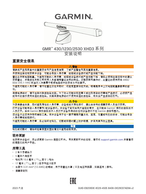
GMR™430/1230/2530 XHD3 系列安装说明重要安全信息未按照这些说明安装本设备,可能会导致人身伤害、船舶或设备损坏或产品性能下降。
雷达会发射电磁能量。
为避免可能的人身伤害、船舶或设备损坏或产品性能下降,请务必按照这些说明中的建议安装雷达,并确保在发射之前所有人员都清楚雷达波束的路径。
正确安装和操作时,此雷达的使用符合 ANSI/ IEEE C95.1-1992 标准对人体暴露于射频电磁场中的安全水平的要求。
为避免可能的人身伤害,请勿在雷达正在发射时,近距离直接注视天线。
眼睛是身体上对电磁能量最敏感的部位。
连接电源线时,请勿去除内联保险丝支架。
为了防止可能出现因着火或过热导致的伤害或产品损坏,必须按产品规格中的指示使用合适的保险丝。
如果连接电源线时不使用合适的保险丝,将失去产品保修的权利。
打开设备可能导致人身伤害和/或设备损坏。
本设备不含可由用户维修的零件,且只能由 Garmin®授权的服务技术人员打开。
由非 Garmin 授权服务技术人员打开设备所造成的任何设备损坏不在 Garmin 保修范围内。
该设备只应该用作导航辅助工具。
将本设备用于任一要求精确测量方向、距离、位置或地形的场合,可能会导致人身伤害或船舶损坏。
为避免可能的人身伤害,务必始终在钻孔、切割或研磨时戴上防护眼镜、护耳用具和防尘面具。
注意钻孔或切割时,请始终检查表面反面的情况以避免船舶受损。
软件更新在安装本设备时,您必须更新 Garmin 海图仪软件。
有关更新软件的说明,请访问并查看您的海图仪的用户手册。
所需工具• 2 号十字螺丝刀•5 毫米六角扳手•钻机和 15.0 毫米(19/32 英寸)钻头•17 毫米(21/32 英寸)扳手和扭力扳手•长度为 3.31 mm² (12 AWG) 的铜线,用于将雷达外罩(以及电压转换器,如果适用)接地。
•海事密封剂安装注意事项别之中,雷达的安装位置与人之间的距离决不能小于产品规格中列出的最小安全距离值。
1230系列氧化锆操作手册

本文由tiansi2002贡献doc文档可能在WAP端浏览体验不佳。
建议您优先选择TXT,或下载源文件到本机查看。
使用注意事项:使用注意事项:1.探头采用主电源供电,可能会对维护人员造成伤害。
在检查探头时请先断电源,探头必须接地。
2.燃烧或空气控制系统很危险,必须有专人管理以至于在设备无效情况下系统不会爆炸。
通常情况下空气应流通,不致于在废气中产生超过 400ppm 的 CO。
废气中的 CO 应该采用独立 CO 测量装置,通常为红外式或单元型。
3.氧探头加热超过 700°并且是源端,既然当关闭电源,会发生生料泄露, C 分析仪在切断主电源时,采用联锁继电器来切断探头加热电源。
不加热探头能满足此种应用要求,但当温度超过 650°时读数显示才有效。
C4.氧化锆分析仪信号衰减,和报警继电器报警显示完全燃烧。
如果为不完全燃烧,则显示读数降低就不能作为报警控制用了,添加催化剂或热电导桥实现充分燃烧,将更适合于那些不完全燃烧的场所。
5.如果需要差压变送器用于反馈补偿过程压力到分析仪,则必须精确可靠;否则错误的压力读数会导致氧化锆的读数错误。
概述 1230 系列分析仪和传感器 1230 系列分析仪和传感器使用氧化锆基片和先进材料作成,有如下优点:※响应速度快,典型值不到四秒※冗余设计提高可靠性※探头寿命长,阻抗大,耐腐蚀※低成本维护※减少在安装、启动过程中由于热震动和机械损坏探头 1230 系列氧化锆分析仪传感器易于安装、维护;提供氧含量的直接测量;在线自动标定(根据需要)。
带加热 1231 型传感器不带加热的 1232 型传感器1.传感器性能指标型号 1231 1232应用环境长度过程连接探头直径电气连接电缆加热器烟道气温度计响应时间探头头部温度参考气标定气流量参考气连接烟道气温度低于 900°C 烟道气温度 700-1400°C,且不含如天然气,轻油等杂质。
250-2000mm 1 1/2" NPT 34mm 500-1500mm 3/4" NPT 19mm1/2" NPT 防水接头或航空插头,危险场合可选配防爆密封接头。
PCI-1230用户手册

DO2
DO1 DO0
R
TTL Digital Input
03H
DI15 DI14 DI13
DI12
DI11
DI10
DI9
ut
DO15 DO14 DO13 DO12 DO11 DO10
DO9 DO8
04H
R
Board ID
BD3
BD2
BD1 BD0
[9]
Page 9 of 16
拨码开关设置以及功能选择:
SW2:板 ID 选择 开关选择(开关的箭头指向) 0 1 2 3 4 5 6 7 8 9 A B C D E F
输入输出说明:
板 ID 15 14 13 12 11 10 9 8 7 6 5 4 3 2 1 0
1 TTL 输入输出
PCI1230 具有 16 路 TTL 电平输入和 16 路 TTL 电平输出,输入自带 10K Ω 上拉
2011-10-14 15:56:21
深圳市升立德科技有限公司 电话:0755-86196687 传真:0755-86317181 地址:深圳市南山南山大道南光商务大厦 1010
PCI-1230 光隔离 16 通道输入 16 通道输出卡
使用说明书
V2.01 2010-1
[1]
Page 1 of 16
l 200mA 反向电流输出 l 隔离电压 3750Vrms
[4]
Page 4 of 16
引脚描述:
2011-10-14 15:56:23
深圳市升立德科技有限公司 电话:0755-86196687 传真:0755-86317181 地址:深圳市南山南山大道南光商务大厦 1010
其中:
IDI_n(n=0~15) EICOM EOGND VCOM
1230控制器使用手册

Emergency Reverse Parameters ..........................................33 Wiring Check, Speed, Direction Interlock, Time Limit, Accel Rate, Switch Normally Closed
Controller Cloning .....................................................................44
4. MONITOR MENU ................................................................45
iv
Curtis 1230 Manual, Rev. C
CONTENTS
Hydraulics Parameters........................................................40 Lift PV Max, Lift PV Min, Lift PV Accel Rate, Lift PV Decel Rate, Lower PV Max, Lower PV Min, Lower PV Accel Rate, Lower PV Decel Rate, PV Dither, Pump Start Delay, Pump BDI Lockout, Lift PV Hold Delay, Load Hold Delay, Open Load Hold During Lift, Hyd Throttle Type, Hyd Throttle Deadband, Hyd Throttle Max, Hyd Throttle Map, Max Pump Run Time
1230 用户手册

1230系列尊敬的用户:您好!欢迎您使用CURTIS控制器。
为了您在使用我们的产品前,能够更好的了解使用说明书交流控制器客服热线:**************************地址:苏州市金山路86号邮编:215129销售热线:************************地址:北京市中粮广场B座906邮编:1000051物料搬运车作业台`表123基 础 篇l 通风性和散热性好; l 位置清洁干净; l 靠近电机和电池; l手持单元易插拔;安装布局电机是将电池电能转换成机械能,驱动电动车车轮旋转的部件。
请在接线前翻阅第18页 注意事项! 5MODE SELECT TYPE模式选择类型 9备注:*2 0 3 0 -NO. 功 能 菜 单 最小值 最大值 缺省值 单位Rate Parameters -------------------------------------------------- ACCEL RATE, M1-M2模式1/模式2加速器最大位置时的加速率1值越大,加速响应越慢0.1 5 2 sDECEL RATE, M1-M2模式1/模式2加速器减小时的减速率2值越大,减速响应越慢0.1 10.0 2 sBRAKE RATE,M1-M2方向改变时的减速率3值越大,减速响应越慢0.1 5.0 0.2 sFAST STOP RATE全速时的减速率4值越大,减速响应越慢0.1 5.0 0.5 sACCEL RELEASE RATE加速释放率5值越大,加速时减速响应越慢0.1 1.0 0.3 s Speed parameters -------------------------------------------------MIN SPEED,M1-M2模式1/模式2的最小速度6值越大,速度越快0 50 0 %MAX SPEED,M1-M2模式1/模式2的最大速度7值越大,速度越快5 100 100 %SPEED LIMIT TYPE速度限制类型8备注:*10 3 0 - MultiMode Parameters ---------------------------------------------COAST DECEL RATE自由滑行减速率10值越大,减速时间越长0.1 20 2 s表36表3续NO. 功 能 最小值 最大值 缺省值 单位 ANTI TIEDOWN11 防固定高速模式 - - OFF - Throttle Parameters ---------------------------------------------THROTTLE TYPE121 52 -加速器类型备注:*3THROTTLE DEADBAND13 加速器死区 0 30 5 %THROTTLE MAX14 最大加速器输入值 40 100 80 %THROTTLE MAP15加速器曲线5 90 20 %值越大,加速越猛POT LOW CHECK16 加速器低端检测 - - 0FF - Sequencing Parameters ------------------------------------------- INTERLOCK NORMALLY OPEN17 互锁开关是否常开- - ON -SEQUENCING DELAY18 操作顺序延时 0 9 0.1 sSTATIC RETURN TO OFF190 3 OFF -SRO功能备注:* 4HIGH PEDAL DISABLE200 2 ON -HPD功能备注:* 5MAIN CONT INTERLOCK TYPE210 1 0 -主接触器互锁类型备注:* 6MAIN CONT OPEN DELAY22 主接触器断开延时 0 60 10 sMAIN CONTACTOR CHECK23- - ON - 主接触器故障检测Brake Parameters7表3续NO. 功 能 最小值 最大值 缺省值 单 位 BRAKE FAULT CHECK24 刹车故障检测- - ON %BRAKE DELAY刹车延时25制越大,延时时间越长0 10 1 sBRAKE HOLD VILTAGE刹车线圈保持电压26制越大,保持电压越高0 100 100 %BRAKE DRIVER TYPE27 刹车驱动类型 0 3 0 -ANTI-ROLLBACK TIME28 防后滑时间 0 1000 400 ms Emergency Reverse Parameters--------------------------------------WIRING CHECK29 紧急反向接线检查- - ON -SPEED紧急反向速度30值越大,速度越快10 100 100 %DIRECTION INTERLOCK31 紧急反向方向互锁- - ON - TIME LIMIT紧急反向时间限制32值越大,紧急反向时间越长0 10 3 sACCEL RATE紧急反向加速率33制越大,越柔和0.1 5 0.5 sSWITCH CLOSED34 紧急反向开关状态 - - OFF-MIN MOTOR VOLTAGE最小电机电压35值越小,启动时电压越小0 6 0.5 VNOMINAL MOTOR VOLTAGE正常电机电压 36电机铭牌 7 30 17 VMotor Parameters-------------------------------------------------------8表3续NO. 功 能 最小值 最大值 缺省值 单位NOMINAL MOTOR FREQUENCY3720 400 80 HZ正常电机频率电机铭牌MAX MOTOR SPEED381000 10000 2300 RPM 最大电机速度电机铭牌NUMBER OF MOTOR POLES2 8 4 - 39电机极数电机铭牌ENCODER PULSES/REVOLUTION4032 128 32 -电机编码器脉冲数电机铭牌SWAP ENCODER DIRECTION41 交换编码器AB相- - OFF -FAILSAFE DELAY422 20 20 s故障时延时电机运行故障检测用Control Parameters-------------------------------------------------------P GAIN0.00 1.00 0.3 - 43P增益越小,对加速器和负载的变化反应越低I GAIN440.00 1.50 0.3 -I 增益越小,对加速器和负载的变化反应越低ACCEL SLIP1 50 5 HZ 45加速时滑差值越大,加速时频率差越大REGEN SLIP1 50 4 HZ 46再生时滑差值越大,减速时频率差越大SLIP BOOST0 10 1 - 47弱磁区滑差与速度的斜率可调整横功率区域的最大电流PULL-OUT SLIP1 50 9.5 HZ 48高速时,最大的频率差值太大易引起震荡ACCEL SLIP VOLTAGE5 50 5.5 V 49接近0速时的最大滑差电压值越大加速时电流越大93续NO. 功 能 最小值 最大值 缺省值 单 位 REGEN SLIP VOLTAGE0 10 0.2 V 48接近0速时的最大滑差电压值越大减速时再生电流越大ACCEL COMP0 5 1 - 49加速时电抗补偿值越小,加速时随着速度增加电流和扭矩越小REGEN COMP0 5 3 - 50再生时电抗补偿值越小,再生时随着速度增加电流和扭矩越小REGEN VOLTAGE OFFSET0 5 0.2 - 51再生电压偏移大的值,可用于减小再生时电压Battery Parameters------------------------------------------------------FULL VOLTAGEEBV FBV 2.04 V 52电池满时的放电电压调整电池放电曲线用EMPTY VOLTAGE0.9 FBV 1.73 V 53电池空时的放电电压调整电池放电曲线用BDI RESET BATTERY VOLTAGEFBV 3 2.09 V 54BDI复位时的电池电压调整电池充电曲线用BATTERY RECHARGE LEVEL20 50 30 V 55电池充电提示电压调整电池充电曲线用LOW VOLTAGE LEVEL1.33 1.67 5 V 56电池欠压值调整电池充电曲线用Hourmeter parameters----------------------------------------------------ENABLE TOTAL SERVICE HOURS57 总服务时间计时使能- - OFF -ENABLE DRIVE SERVICE HOURS58 行走时间计时使能 - - OFF -ADJUST HOURS0 9999990 h 59小时计调整用于小时计预设表3续NO. 功 能 最小值 最大值 缺省值 单位 SET TOTAL HOURS60 设置总的计时时间使能- - OFF -SET DRIVE HOURS61 设置行走计时时间使能 - - OFF -TOTAL SERVICE HOURS100 5000 5000 h 62下一次总保养期时间值越大,时间越长DRIVE SERVICE HOURS63100 5000 5000 h 下一次行走保养期时间值越大,时间越长TOTAL DISABLE HOURS640 500 10 h总的禁止时间值越大,时间越长DRIVE DISABLE HOURS0 500 10 h 65总的行走禁止时间值越大,时间越长DRIVE DISABLE SPEED0 80 20 % 66禁止时间到后的速度制越大,速度越快SERVICE TOTAL EXPIRED67 总的服务时间是否已满 - - OFF -SERVICE DRIVE EXPIRED68 总的行走时间是否已满 - - 0FF -Other System Parameters -----------------------------------------------------POWER SAVE DELAY0 240 30 - 69进入省电模式的时间设为0,无法进入省电模式INHIBIT INPUT TYPE0 2 0 - 70禁止输入的类型备注:*7FAULT CODE71 状态灯指示故障的类别 - - ON -备 注*1. 速度限制类型:-------------------------------------------------------------------------0. 无1. 线性的速度限制(限速电位器)2. 常开开关3. 常闭开关*2. 模式选择类型:-------------------------------------------------------------------------0. 标准的M1和M2类型1. 行进模式2. 滑行模式3. 安全行进模式*3. 加速器类型:---------------------------------------------------------------------------1. 2线加速器,5K-02. 单端3线,1K-10K电位器或0-5V3. 2线加速器,0-5K4. 摇摆型1K-10K电位器或0-5V5. 三阶段加速器*4. SRO类型:------------------------------------------------------------------------------0. 无1. 互锁+任一方向输入2. KSI+互锁+任一方向输入3. KSI+互锁+前进方向输入*5. SRO类型:------------------------------------------------------------------------------0. 无1. KSI和互锁必须优先于加速器输入2. KSI必须优先于加速器输入*6. 主接触器互锁类型:------------------------------------------------------------------ 0. 主接触器在互锁和加速器输入后闭合1.主接触器在互锁输入后闭合*7. 禁止输入类型:------------------------------------------------------------------------ 0.无1.常开开关2.常闭开关序号 NO. 监 控 项 目 表 示 备 注1 BATTERY VOLTAGE 电池电压 电压2 BSOC 电池充电状态 百分比3 MOTOR SPEED 电机速度 转速4 MOTOR VOLTAGE 电机电压 电压5 MOTOR FREQUENCY 电机频率 频率6 SLIP 滑差 频率7 THROTTLE INPUT 加速器输入 百分比8 INTERLOCK SWITCH 互锁开关 状态9 FORWARD SWITCH 前进开关 状态10 MODE SWITCH 模式开关 状态11 EMERGENCY REVERSE SWITCH 紧急反向开关 状态12 INHIBIT INPUT 禁止输入 状态13 SPEED LIMIT 速度限制 百分比14 HORN SWITCH 喇叭开关 状态15 HYD THROTTLE INPUT 液压加速器输入 百分比 2X02系列无16 LIFT SWITCH 提升开关 状态 2X02系列无17 LOWER SWITCH 下降开关 状态 2X02系列无18 AUX OUTPUT1 辅助驱动1 状态 2X02系列无19 AUX OUTPUT2 辅助驱动2 状态 2X02系列无20 PROP VALVE PWM 比例阀输出 百分比 2X02系列无21 LOAD HOLD VALVE 保持阀状态 状态 2X02系列无22 TEMPERATURE 控制器温度 温度23 MAIN CONTACTOR 主接触器状态 状态24 TOTAL HOURMETER HOURS 总服务小时 小时25 DRIVER HOURMETER HOURS 行走工作时间 小时26 FAULT POSITION 故障位置 状态表5NO 编 程 器 显 示 代码故 障 现 象 故 障 诊 断MOTOR SPEEDENCODER电机速度编码器错误1) 编码器接线错误 2) 控制器故障 1 MOTOR FAILSAFE1.2 电机堵转或转速超设定1) 编码器接线错误 2) 电机锁死 3) 刹车扭矩不足 4) P/I 增益设置过低 5) 故障延时太短 MOTOR OVERCURRENT 电机过流1) 电机接线错误 2) 控制器故障 2 MOTOR OUTPUT FAULT1.3 电机输出保护被触发 1) 电机接线错误 2) 控制器故障3 STATIC RETURN TOOFF1.4 SRO 顺序故障1) 不合适的操作顺序 2) SRO类型选择错误 3) 未调节加速器 4) 方向开关开路 5) 顺序延时太短 6)错误的加速器类型4 THROTTLE WIPERHIGH2.1 加速器滑端高故障1) 加速器输入端与B+短路2) 加速器故障3) 错误的加速器类型选择 4) 速度限制电位器接线错误 5 EMERGENCY REVERSE WIRING OPEN2.2 紧急反向配线故障 1) 紧急反向接线或检测线断路 6 HIGH PEDAL DISABLE2.3 HPD 故障 1) 不合适的操作顺序 2) 错误的HPD 类型选择 3) 未调节加速器 4) 互锁开关开路 5) 顺序延时太短6) 加速器类型选择错误 7 THROTTLEWIPER LOW 2.4 加速器滑端低故障 1) 加速器输入端与B-短路 2) 加速器故障 3) 加速器类型错误 8 MULTIPLEXER FAULT 3.1 拓展口功能故障 1) 拓展口功能卡未接 2) 拓展口功能卡接线不当 3) 加速器类型错误 9 MAIN CONTACTOR3.2 主接触器未接或粘连1) 主接触器线圈开路 2) 主接触器无 3) 主接触器接线无 4) 主接触器粘连 5)主接触器驱动短路PRECHARGE 预充电故障 1)控制器故障2)电池电压低10 BRAKE FAULT 3.3 刹车接线或驱动故障 1)刹车线圈开路2)刹车未接3)刹车线未接4)刹车驱动短路SERVICE TOTALDISABLED总服务时间到期 1)总服务时间到SERVICE DRIVEDISABLED总行驶时间到期 1)行驶时间到SERVICE TOTAL EXPIRED 总维护时间到 1)总维护时间到11SERVICE DRIVEEXPIRED 4.1行驶维护时间到 1)行驶维护时间到BATTERY OVERVOLTAGE 电池电压太高 1)电池电压高于过压点2)充电器未拔12BATTERYUNDERVOLTAGE 4.2电池电压太低 1)电池电压低于过压点2)电池端腐蚀3)电池接线松动13 TEMPERATURECUTBACK 4.3 控制器温度太高或太低1)温度大于85°或小于-25°2)过载3)控制器安装不合适4)在极端环境下运行14 ANTI TIEDOWN 4.4 启动时模式开关激活 1)模式开关与B+短路2)M2开关闭合15 HARDWARE FAILURE 5.1 硬件 故障 1)控制器故障16 SOFTWARE FAILURE 5.2 软件故障 1)控制器故障17 PARAMETERSCORRUPT5.3 参数错误 1)控制器故障当控制器报故时,您可以使用Monitor菜单和 进行检测1. Monitor 菜单检测步骤a . 加速器输入检测步骤b .方向检测第2步:进入Monitor 的INPUT 菜单,观察参数THROTTLE第1步:悬空车轮第3步:THROTTLE 值应随加速器的旋转,线性增加步骤d. 主接触器状态检测步骤a. 检测前请使用30Ω,5W电阻对B+,B-端子放电: 步骤b. 控制器检测项目如下:所有数值均应测定3次以上:万用表拨至Ω档(电阻值测定) 万用表拨至档(极性值测定)请按如下步骤进行控制器调试: 步骤一. 电机基本参数设置步骤二. 匹配参数设置 CURTIS调试篇步骤三. 设置加速器类型步骤四. 调节加速器范围步骤五. 调节前进/后退速度步骤六. 调节加速率与减速率调试 篇CURTIS前进/后退加速率:M1 ACCEL RATE M2 ACCEL RATE M1 DECEL RATE M2 DECEL RATE死区调节:THRTL DEADBAND 范围调节: THRTL MAX 调节结果需使THROTTLE 能在0%~100%范围内变化 前进/后退速度: M1 MAX SPD M2 MAX SPD M1 MIN SPD M2 MIN SPD测量车辆满载或空载爬坡电流测 量 篇CURTIS请您在使用产品前,仔细阅读以下内容(如有疑问请与CURTIS 工程师联系):------ 注:如出现下述情况,将有可能严重损坏控制器!1请您在使用产品前,仔细阅读以下内容(如有疑问请与CURTIS 工程师联系):------ 注:如出现下述情况,将有可能严重损坏控制器!34 危险严 禁 电 机 短 路。
ADS1230IPW芯片手册

BurrĆBrown Products from TexasInstrumentsFEATURESDESCRIPTIONAPPLICATIONSREFP REFN CAP DVDDDGNDGAIN AINPAINNAVDD CAP CLKIN AGND ADS1230SBAS366–OCTOBER 200620-Bit Analog-to-Digital ConverterFor Bridge Sensors•Complete Front-End for Bridge Sensor The ADS1230is a precision 20-bit analog-to-digital converter (ADC).With an onboard low-noise •Onboard PGA with Gain of 64or 128programmable gain amplifier (PGA),onboard •Onboard Oscillator oscillator,and precision 20-bit delta-sigma ADC,the •RMS Noise:ADS1230provides a complete front-end solution for 40nV at 10SPS (G =128)bridge sensor applications including weigh scales,88nV at 80SPS (G =128)strain gauges,and pressure sensors.•18-Bit Noise-Free ResolutionThe low-noise PGA has a gain of 64or 128,•Selectable 10SPS or 80SPS Data Rates supporting a full-scale differential input of ±39mV or ±19.5mV,respectively.The delta-sigma ADC has •Simultaneous 50Hz and 60Hz Rejection at 20-bit effective resolution and is comprised of a 10SPS3rd-order modulator and 4th-order digital filter.Two •External Voltage Reference up to 5V for data rates are supported:10SPS (with both 50Hz Ratiometric Measurements and 60Hz rejection)and 80SPS.The ADS1230can be clocked by the internal oscillator or an external •Simple,Pin-Driven Controlclock source.Offset calibration is performed •Two-Wire Serial Digital Interface on-demand,and the ADS1230can be put in a •Tiny 16-pin TSSOP Package low-power standby mode or shut off completely in •Supply Range:2.7V to 5.3Vpower-down mode.•–40°C to +85°C Temperature RangeAll of the features of the ADS1230are controlled by dedicated pins;there are no digital registers to program.Data are output over an easily-isolated serial interface that connects directly to the MSP430•Weigh Scales and other microcontrollers.•Strain Gauges The ADS1230is available in a TSSOP-16package •Pressure Sensorsand is specified from –40°C to +85°C.•Industrial Process ControlPlease be aware that an important notice concerning availability,standard warranty,and use in critical applications of Texas Instruments semiconductor products and disclaimers thereto appears at the end of this data sheet.All trademarks are the property of their respective owners.PRODUCTION DATA information is current as of publication date.Copyright ©2006,Texas Instruments IncorporatedProducts conform to specifications per the terms of the Texas Instruments standard warranty.Production processing does not necessarily include testing of all parameters.ORDERING INFORMATIONABSOLUTE MAXIMUM RATINGSADS1230SBAS366–OCTOBER2006This integrated circuit can be damaged by ESD.Texas Instruments recommends that all integrated circuits be handled with appropriate precautions.Failure to observe proper handling and installation procedures can cause damage.ESD damage can range from subtle performance degradation to complete device failure.Precision integrated circuits may be more susceptible to damage because very small parametric changes could cause the device not to meet its published specifications.For the most current package and ordering information,see the Package Option Addendum at the end of this document,or see the TI website at .over operating free-air temperature range(unless otherwise noted)(1)ADS1230UNITAVDD to AGND–0.3to+6VDVDD to DGND–0.3to+6VAGND to DGND–0.3to+0.3V100,Momentary mAInput Current10,Continuous mAAnalog Input Voltage to AGND–0.3to AVDD+0.3VDigital Input Voltage to DGND–0.3to DVDD+0.3V Maximum Junction Temperature+150°C Operating Temperature Range–40to+85°C Storage Temperature Range–60to+150°C(1)Stresses beyond those listed under Absolute Maximum Ratings may cause permanent damage to the device.These are stress ratingsonly,and functional operation of the device at these or any other conditions beyond those indicated is not implied.Exposure toabsolute-maximum-rated conditions for extended periods may affect device reliability.2Submit Documentation FeedbackELECTRICAL CHARACTERISTICSADS1230 SBAS366–OCTOBER2006All specifications at T A=–40°C to+85°C,AVDD=DVDD=REFP=+5V,REFN=AGND,and Gain=64,unless otherwise noted.ADS1230PARAMETER CONDITIONS MIN TYP MAX UNIT Analog InputsFull-Scale Input Voltage(AINP–AINN)±0.5V REF/PGA V Common-Mode Input Range AGND+1.5V AVDD–1.5V V Differential Input Current±2nA System PerformanceResolution No Missing Codes20BitsInternal Oscillator,SPEED=High69.58086.4SPSInternal Oscillator,SPEED=Low8.681010.8SPS Data RateExternal Oscillator,SPEED=High f CLK/61,440SPSExternal Oscillator,SPEED=Low f CLK/491,520SPS Digital Filter Settling Time Full Settling4ConversionsDifferential Input,End-Point Fit,G=64±10ppm Integral Nonlinearity(INL)Differential Input,End-Point Fit,G=128±6ppm Input Offset Error(1)±3ppm of FS Input Offset Drift±10nV/°C Gain Error±0.8% Gain Drift±4ppm/°CInternal Oscillator,f DATA=10SPS90dBNormal-Mode Rejection(2)External Oscillator,fDATA =10SPS100dBf IN=50Hz or60Hz,±1HzCommon-Mode Rejection at DC,∆VDD=0.1V110dBf DATA=10SPS53nV,rms Input-Referred Noisef DATA=80SPS100nV,rms Power-Supply Rejection at DC,∆VDD=0.1V90100dB Voltage Reference InputVoltage Reference Input(V REF)V REF=REFP–REFN 1.5AVDD AVDD+0.1V V Negative Reference Input(REFN)AGND–0.1REFP–1.5V Positive Reference Input(REFP)REFN+1.5AVDD+0.1V Voltage Reference Input Current10nA DigitalAll digital inputs except CLKIN0.7DVDD DVDD+0.1V V IHCLKIN0.7DVDD 5.1VLogic Levels V IL DGND0.2DVDD V V OH I OH=1mA DVDD–0.4VV OL I OL=1mA0.2DVDD VInput Leakage0<V IN<DVDD±10µA External Clock Input Frequency(f CLKIN)0.2 4.91526MHz Serial Clock Input Frequency(f SCLK)5MHz(1)Offset calibration can minimize these errors to the level of noise at any temperature.(2)Specification is assured by the combination of design and final production test.3Submit Documentation FeedbackADS1230SBAS366–OCTOBER 2006ELECTRICAL CHARACTERISTICS (continued)All specifications at T A =–40°C to +85°C,AVDD =DVDD =REFP =+5V,REFN =AGND,and Gain =64,unless otherwise noted.ADS1230PARAMETERCONDITIONSMINTYPMAXUNITPower SupplyPower-Supply Voltage (AVDD,DVDD)2.75.3V Normal Mode,AVDD =3V9001400µA Normal Mode,AVDD =5V 9001400µA Analog Supply CurrentStandby Mode 0.11µA Power-Down0.11µA Normal Mode,DVDD =3V 60100µA Normal mode,DVDD =5V95140µA Digital Supply CurrentStandby Mode,SCLK =High,DVDD =3V 4565µA Standby Mode,SCLK =High,DVDD =5V 6580µA Power-Down0.2µA Normal Mode,AVDD =DVDD =3V2.9 4.5mW Power Dissipation,TotalNormal Mode,AVDD =DVDD =5V 5.07.7mW Standby Mode,AVDD =DVDD =5V0.30.4mW4Submit Documentation FeedbackPIN CONFIGURATIONDVDD DGND CLKIN GAIN CAP CAP AINP AINNDRDY/DOUT SCLK PDWN SPEED AVDD AGND REFP REFN12345678161514131211109ADS1230ADS1230SBAS366–OCTOBER 2006PW PACKAGE TSSOP-16(Top View)PIN DESCRIPTIONS5Submit Documentation FeedbackNOISE PERFORMANCEADS1230SBAS366–OCTOBER 2006The ADS1230offers outstanding noise performance.Table 1summarizes the typical noise performance with inputs shorted externally for different data rates and values.The RMS and Peak-to-Peak noise are referred to the input.The effective number of bits (ENOB)is defined as:ENOB =ln (FSR/RMS noise)/ln(2)The Noise-Free Bits are defined as:Noise-Free Bits =ln (FSR/Peak-to-Peak Noise)/ln(2)Where:FSR (Full-Scale Range)=V REF /Gain.Table 1.Noise Performance for AV DD =5V and V REF =5VRMS NOISEPEAK-TO-PEAK NOISE (1)ENOB DATA RATEGAIN (nV)(nV)(RMS)NOISE-FREE BITS645329020.518101284019819.817.56410048019.517.3801288848018.716.3(1)Peak-to-peak data are based on direct measurement.Table 2.Noise Performance for AV DD =3V and V REF =3VRMS NOISEPEAK-TO-PEAK NOISE (1)ENOB DATA RATEGAIN (nV)(nV)(RMS)NOISE-FREE BITS644629020.618101284925919.617.26410057619.5178012810246118.516.3(1)Peak-to-peak data are based on direct measurement.6Submit Documentation FeedbackTYPICAL CHARACTERISTICS43211000800600400200O u t p u t C o d e (L S B )Time (Reading Number)3210-1-2-3-4-5-61000800600400200O u t p u t C o d e (L S B )Time (Reading Number)9008007006005004003002001000321O c c u r r e n c eOutput Code (LSB)40035030025020015010050012-5-4-3-2-1O c c u r r e n c eOutput Code (LSB)0-1-2-3-4-5-61000800600400200O u t p u t C o d e (L S B )Time (Reading Number)86420-2-4-6-8-101000800600400200O u t p u t C o d e (L S B )Time (Reading Number)ADS1230SBAS366–OCTOBER 2006At T A =+25°C,AVDD =DVDD =REFP =5V,and REFN =AGND,unless otherwise noted.NOISE PLOTNOISE PLOTFigure 1.Figure 2.NOISE HISTOGRAMNOISE HISTOGRAMFigure 3.Figure 4.NOISE PLOTNOISE PLOTFigure 5.Figure 6.7Submit Documentation Feedback500450400350300250200150100500-5-4-3-2-1O c c u r r e n c eOutput Code (LSB)25020015010050-7-5-6-4-3-2-101243567O c c u r r e n c eOutput Code (LSB)10008006004002000-200-400-600-800100755025-25-50O f f s e t (n V )T emperature (C)°-0.02-0.03-0.04-0.05-0.06100755025-25-50G a i n E r r o r (%)T emperature (C)°5045403530252015105040-100102030-40-30-20R M S N o i s e (n V )V (mV)IN PGA = 64Data Rate = 10SPS12010080604040-100102030-40-30-20R M S N o i s e (n V )V (mV)IN ADS1230SBAS366–OCTOBER 2006TYPICAL CHARACTERISTICS (continued)At T A =+25°C,AVDD =DVDD =REFP =5V,and REFN =AGND,unless otherwise noted.NOISE HISTOGRAMNOISE HISTOGRAMFigure 7.Figure 8.OFFSET vs TEMPERATUREGAIN ERROR vs TEMPERATUREFigure 9.Figure 10.NOISE vs INPUT SIGNALNOISE vs INPUT SIGNALFigure 11.Figure 12.8Submit Documentation Feedback105-5-1040-100102030-40-30-20I N L (p p m )V (mV)IN1.00.50-0.5-1.0-1.5-2.020010-20-10I N L (p p m )V (mV)IN 120010008006004002000100755025-25-50A n a l o g C u r r e n t (A )m T emperature (C)°97969594939291908988100755025-25-50D i g i t a l C u r r e n t (A )m T emperature (C)°9.859.809.759.70100755025-25-50D a t a R a t e (S P S )T emperature (C)°ADS1230SBAS366–OCTOBER 2006TYPICAL CHARACTERISTICS (continued)At T A =+25°C,AVDD =DVDD =REFP =5V,and REFN =AGND,unless otherwise noted.INTEGRAL NONLINEARITYINTEGRAL NONLINEARITYvs INPUT SIGNALvs INPUT SIGNALFigure 13.Figure 14.ANALOG CURRENT vs TEMPERATUREDIGITAL CURRENT vs TEMPERATURE(Normal Mode)(Normal Mode)Figure 15.Figure 16.DATA RATE vs TEMPERATUREFigure 17.9Submit Documentation FeedbackOVERVIEWANALOG INPUTS (AINP,AINN)Bypass CapacitorLOW-NOISE PGAADS1230SBAS366–OCTOBER 200664)or 0mV to +19.5mV (Gain =128).The inputs of the ADS1230are protected with internal diodes The ADS1230is a precision,20-bit ADC that connected to the power-supply rails.These diodes includes a low-noise PGA,internal oscillator,clamp the applied signal to prevent it from damaging third-order delta-sigma (∆Σ)modulator,and the input circuitry.fourth-order digital filter.The ADS1230provides a complete front-end solution for bridge sensor applications such as weigh scales,strain guages,and pressure sensors.Clocking can be supplied by an external clock or by a precision internal oscillator.Data can be output at 10SPS for excellent 50Hz and 60Hz rejection,or at 80SPS when higher speeds are needed.The ADS1230is easy to configure,and all digital control is accomplished through dedicated pins;there are no registers to program.A simple two-wire serial interface retrieves the data.The input signal to be measured is applied to the input pins AINP and AINN.The ADS1230accepts differential input signals,but can also measure unipolar signals.When measuring unipolar (or Figure 18.Simplified Diagram of the PGA single-ended signals)with respect to ground,connect the negative input (AINN)to ground and connect the input signal to the positive input (AINP).Note that when the ADS1230is configured this way,By applying a 0.1µF external capacitor (C EXT )across only half of the converter full-scale range is used,two capacitor pins combined with the internal 2k Ωsince only positive digital output codes are produced.resistor R INT (on-chip),a low-pass filter with a corner frequency of 720Hz is created to bandlimit the signal path before the modulator input.This low-pass filter serves two purposes.First,the input signal is The ADS1230features a low-drift,low-noise PGA bandlimited to prevent aliasing as well as to filter out that provides a complete front-end solution for bridge the high-frequency noise.Second,it attenuates the sensors.A simplified diagram of the PGA is shown in chopping residue from the amplifier to improve Figure 18.It consists of two chopper-stabilized temperature drift performance.It is not required to and A2)and three accurately-matched use high-quality capacitors (such as ceramic or resistors (R 1,R F1,and R F2),which construct a tantalum capacitors)for a general application.differential front-end stage with a gain of 64,followed However,high-quality capacitors such as poly are by gain stage A3(Gain =1or 2).The PGA inputs recommended for high-linearity applications.are equipped with an EMI filter,as shown in Figure 18.The cutoff frequency of the EMI filter is By using AVDD as the reference input,the bipolar input ranges from –39mV to +39mV (Gain =64)or –19.5mV to +19.5mV (Gain =128),and the unipolar input ranges from 0mV to +39mV (Gain =10Submit Documentation FeedbackVOLTAGE REFERENCE INPUTSCLOCK SOURCESZ EFF+12fMODCBUFZ EFF+1(2)(76.8kHz)(32.5fF)+200M WESD diodes protect the reference inputs.To prevent (REFP,REFN)these diodes from turning on,make sure thevoltages on the reference pins do not go below GND The voltage reference used by the modulator is by more than100mV,and likewise,do not exceed generated from the voltage difference between AVDD by100mV:REFP and REFN:V REF=REFP–REFN.Thereference inputs use a structure similar to that of the GND–100mV<(REFP or REFN)<AVDD+100mV analog inputs.In order to increase the referenceinput impedance,a switching buffer circuitry is usedto reduce the input equivalent capacitance.AThe ADS1230can use an external clock source or simplified diagram of the circuitry on the referenceinternal oscillator to accommodate a wide variety of inputs is shown in Figure19.The switches andapplications.Figure20shows the equivalent circuitry capacitors can be with an effectiveof the The CLK_DETECT block impedance of:determines whether the crystal oscillator/externalclock signal is applied to the CLKIN pin so that theinternal oscillator is bypassed or activated.When theCLKIN pin frequency is above~200kHz,the Where:CLK_DETECT output goes low and shuts down thef MOD=modulator sampling frequency(76.8kHz)internal oscillator.When the CLKIN pin frequency isC BUF=input capacitance of the buffer below~200kHz,the CLK_DETECT output goes highand activates the internal oscillator.It is highly For the ADS1230:recommended to hard-wire the CLKIN pin to groundwhen the internal oscillator is chosen.Figure20.Equivalent Circuitry of the ClockSourceAn external clock may be used by driving the CLKINpin directly.The Electrical Characteristics table Figure19.Simplified Reference Input Circuitryshows theinput may be driven with5V logic,regardless of theDVDD or AVDD voltage.FREQUENCY RESPONSEThe ADS1230uses a sinc4digital filter with thefrequency response(f CLK= 4.9152MHz)shown inFigure21.The frequency response repeats atthe modulator sampling frequency of76.8kHz.The overall response is that of a low-passfilter with a–3dB cutoff frequency of3.32Hz with theSPEED pin tied low(10SPS data rate)and11.64Hzwith the SPEED pin tied high(80SPS data rate).Figure21.Frequency ResponseTo help see the response at lower frequencies,Figure22(a)illustrates the response out to100Hz,data rate=10SPS.Notice that signals atmultiples of10Hz are rejected,and thereforesimultaneous rejection of50Hz and60Hz isFigure22.Frequency Response Out To100Hz achieved.The benefit of using a sinc4filter is that everyThe ADS1230data rate and frequency response frequency notch has four zeros on the same location.scale directly with clock frequency.For example,if This response,combined with the low drift internalf CLK increases from4.9152MHz to6.144MHz when oscillator,provides an excellent normal-modethe SPEED pin is tied high,the data rate increases rejection of line-cycle interference.from80SPS to100SPS,while notches also increase Figure22(b)shows the same plot,but zooms in on from80Hz to100Hz.Note that these changes are 60Hz notches with the SPEED pin tied only possible when the external clock source is low(10SPS data rate).With only a±3%variation of applied.the internal oscillator,over100dB of normal-moderejection is achieved.SETTLING TIMEDATA FORMATDATA RATEIn certain instances,large changes in input will The ADS1230outputs 20bits of data in binary two’s require settling time.For example,an external complement format.The least significant bit (LSB)multiplexer in front of the ADS1230can put large has a weight of 0.5V REF /(219–1).The positive changes in input voltage by simply switching the full-scale input produces an output code of 7FFFFh multiplexer input channels.Abrupt changes in the and the negative full-scale input produces an output input will require four data conversion cycles to code of 800000h.The output clips at these codes for settle.When continuously converting,five readings signals exceeding full-scale.Table 4summarizes the may be necessary in order to settle the data.If the ideal output codes for change in input occurs in the middle of the first The ADS1230is a 20-bit ADC.After data conversion conversion,four more full conversions of the is completed,applying 20SCLKs retrieves 20bits of fully-settled input are required to get fully-settled data (MSB first).However,if the SCLKs continue to data.Discard the first four readings because they be applied after 20bits of data are retrieved,the contain only partially-settled data.Figure 23DOUT pin outputs four 1s for the 21st through the illustrates the settling time for the 24th SCLK,as shown in Figure 24.Continuous Conversion mode.Table 4.Ideal Output Code vs Input Signal (1)INPUT SIGNAL V IN (AINP –AINN)IDEAL OUTPUTThe ADS1230data rate is set by the SPEED pin,as shown in Table 3.When SPEED is low,the data rate ≥+0.5V REF /Gain 7FFFFh is This data rate provides the 00001h (+0.5V REF /Gain)/(219–1)lowest noise,and also has excellent rejection of both 000000h 50Hz and 60Hz line-cycle interference.For FFFFFh (–0.5V REF /Gain)/(219–1)applications requiring fast data rates,setting SPEED ≤–0.5V REF /Gain80000hhigh selects a data rate of nominally 80SPS.(1)Excludes effects of noise,INL,offset,Table 3.Data Rate Settingsand gain errors.DATA RATESPEED Internal Oscillator External PIN or 4.9152MHz CrystalOscillator 010SPS f CLKIN /491,520180SPSf CLKIN /61,440Figure 23.Settling Time in Continuous Conversion ModeFigure 24.Data Retrieval FormatDATA READY/DATA OUTPUT (DRDY/DOUT)DATA RETRIEVALSERIAL CLOCK INPUT (SCLK)This digital output pin serves two purposes.First,it The ADS1230continuously converts the analog input indicates when new data are ready by going low.signal.To retrieve data,wait until DRDY/DOUT goes Afterwards,on the first rising edge of SCLK,the low,as shown in Figure 25.After DRDY/DOUT goes DRDY/DOUT pin changes function and begins low,begin data by applying SCLKs.outputting the conversion data,most significant bit Data are shifted out MSB first.It is not required to (MSB)first.Data are shifted out on each subsequent shift out all 20bits of data,but the data must be SCLK rising edge.After all 20bits have been retrieved before new data are updated (within t CONV )retrieved,the pin can be forced high with an or else the data will be overwritten.Avoid data additional SCLK.It then stays high until new data are retrieval during the update period (t UPDATE ).If 24ready.This configuration is useful when polling on SCLKs have been applied,DRDY/DOUT will be high the status of DRDY/DOUT to determine when to since the last four bits have been appended by '1'.begin data retrieval.However,if only 20SCLKs have been applied,DRDY/DOUT remains at the state of the last bit shifted out until it is taken high (see t UPDATE ),indicating that new data are being updated.To avoid This digital input shifts serial data out with each having DRDY/DOUT remain in the state of the last rising edge.As with CLK,this input may be driven bit,the 21st SCLK can be applied to force with 5V logic regardless of the DVDD or AVDD DRDY/DOUT high,as shown in Figure 26.This voltage.This input has built-in hysteresis,but care technique is useful when a the should still be taken to ensure a clean signal.device is polling DRDY/DOUT to determine when Glitches or slow-rising signals can cause unwanted data are ready.additional shifting.For this reason,it is best to make sure the rise and fall times of SCLK are both less than 50ns.Figure25.Data Retrieval TimingFigure26.Data Retrieval with DRDY/DOUT Forced High AfterwardsOFFSET CALIBRATIONDuring this time,the analog input pins are disconnected within the ADC and the appropriate Offset calibration can be initiated at any time to signal is applied internally to perform the calibration.remove the ADS1230inherited offset error.To When the calibration is completed,DRDY/DOUT initiate offset calibration,apply at least two additional goes low,indicating that new data are ready.The 20bits of data plus four bits of first conversion after a calibration is fully settled and '1'.the timing pattern.The 25th valid for use.The offset calibration takes exactly the high.The falling edge of same time as specified in (t CAL )immediately after the the 26th SCLK begins the calibration cycle.falling edge of the 26th SCLK.Additional SCLK pulses may be sent after the 26th SCLK;however,activity on SCLK should be minimized during offset calibration for best results.Figure 27.Offset-Calibration TimingSYMBOL DESCRIPTIONMIN MAX UNITS SPEED =1101.28101.29ms t CAL (1)First data ready after calibrationSPEED =0801.02801.03ms(1)Value given for f CLK =4.9152MHz.For different f CLK frequencies,scale proportional to CLK period.Expect a ±3%variation when an internal oscillator is used.STANDBY MODEWhen t STANDBY has passed with SCLK held high,Standby mode activates.DRDY/DOUT stays high Standby mode dramatically reduces power when Standby mode begins.SCLK must remain high consumption by shutting down most of the circuitry.to stay in Standby mode.To exit Standby mode In Standby mode,the entire analog circuitry is (wakeup),set SCLK low.The first data after exiting powered down and only the clock source circuitry is Standby mode is valid.awake to reduce the wake-up time from the Standby mode.To enter Standby mode,simply hold SCLK high after DRDY/DOUT goes low;see Figure 28.Standby mode can be initiated at any readback;it is not necessary to retrieve all 20bits of data beforehand.Figure 28.Standby Mode Timing (can be used for single conversions)SYMBOL DESCRIPTIONMIN MAX UNITS SPEED =1012.44ms SCLK high after DRDY/DOUT goes t DSS (1)low to activate Standby mode SPEED =0099.94ms SPEED =120µs t STANDBY (1)Standby mode activation time SPEED =020µs SPEED =152.5152.51ms t S_RDY (1)Data ready after exiting Standby modeSPEED =0401.8401.8ms(1)Value given for f CLK =4.9152MHz.For different f CLK frequencies,scale proportional to CLK period.Expect a ±3%variation when an internal oscillator is used.STANDBY MODE WITHTo force an offset-calibration with Standby mode,OFFSET-CALIBRATIONshift 25SCLKs and bring the SCLK pin high to enter Standby mode.Offset-calibration then begins after Offset-calibration can be set to run immediately after wake-up;Figure 29shows the appropriate timing.exiting Standby mode.This option is useful when the Note the needed after wake-up for ADS1230is put in Standby mode for long periods of calibration before data are ready.The first data after time,and offset-calibration is desired afterwards to Standby mode with offset-calibration is fully settled compensate for temperature or supply voltage and can be used right away.changes.Figure 29.Standby Mode with Offset-Calibration Timing (can be used for single conversions)SYMBOL DESCRIPTIONMIN MAX UNITS SPEED =1103103ms Data ready after exiting Standby mode t SC_RDY (1)and calibrationSPEED =0803803ms(1)Value given for f CLK =4.9152MHz.For different f CLK frequencies,scale proportional to CLK period.Expect a ±3%variation when an internal oscillator is used.POWER-DOWN MODEfrom locking up to an unknown state.Power-Down mode can be initiated at any time during readback;it Power-Down mode shuts down the entire ADC is not necessary to retrieve all 20bits of data circuitry and reduces the total power consumption beforehand.Figure 30shows the wake-up timing close to zero.To enter Power-Down mode,simply from hold the PDWN pin low.Power-Down mode also resets the entire circuitry to free the ADC circuitryFigure 30.Wake-Up Timing from Power-Down ModeSYMBOL DESCRIPTIONMINTYP UNITS Internal clock 7.95µs Wake-up time after Power-Down t WAKEUP modeExternal clock0.16µs t PDWN (1)PDWN pulse width26µs(1)Value given for f CLK =4.9152MHz.For different f CLK frequencies,scale proportional to CLK period.Expect a ±3%variation when an internal oscillator is used.APPLICATION EXAMPLESNoise−Free Counts +ǒ2BIT Eff ǓǒFS LC FS ADǓWeigh Scale SystemNoise−Free Counts +ǒ2(17.5)1)Ǔǒ10mV 39mVǓ+95,058Where:Figure 31shows a typical ADS1230hook-up as part scale system.In this setup,the ADS1230BIT EFF =effective noise-free bits (17.5+1bit is configured at a 10SPS data rate.Note that the from software filtering/averaging)internal oscillator is used by grounding the CLKIN FS LC =full-scale output of the load cell (10mV)pin.The user can also apply a 4.9152MHz clock to FS AD =full-scale input of the ADS1230(39mV,the CLKIN pin.For a typical 2mV/V load cell,the when PGA =128)maximum output signal is approximately 10mV for a Therefore:single +5V excitation voltage.The ADS1230can achieve 17.5noise-free bits at 10SPS when PGA =128.With the extra software filtering/averaging (typically done by a microprocessor),an extra bit can be expected.With +5V supply voltage,95,058noise-free counts can be expected from the ADS1230.Figure 31.Weigh Scale Application。
测量特种-1230-030A-3S-IC传感器-用户手册说明书

∙PC Board Mountable Pressure Sensor∙0-100 mV Output∙Current Excitation∙Gage, Differential, and Absolute∙Temperature CompensatedDESCRIPTIONThe 1230 is a high performance temperature compensated, piezoresistive silicon pressure sensor packaged in a dual-in-line configuration. It uses Measurement Specialties’ proprietary UltraStable™ die to provide excellent performance and long-term stability over wide temperatures.Integral temperature compensation is provided over a range of -20°C to +85°C using laser-trimmed resistors. An additional laser-trimmed resistor is included to normalize pressure sensitivity variations by programming the gain of an external differential amplifier. This provides sensitivity interchangeability of ±1%. Absolute, differential and gage pressure ranges from 0-15 to 0-100 psi are available. Multiple lead and tube configurations are available for different applications.Please refer to the 1210 and 1220 for information on products with operating pressures less than 0-15 psi. For voltage excitation, please refer to the Model 1240.FEATURES APPLICATIONS∙Dual-in-Line Package∙Medical Instruments∙-20ºC to +85ºC CompensatedTemperature Range∙Altitude Measurement∙Process Control∙±0.1% Non Linearity∙Factory Automation∙ 1.0% Interchangeable Span(provided by gain set resistor)∙Handheld Calibrators∙Environmental Control∙Solid State ReliabilitySTANDARD RANGESRange psia psid psig0 to 2 ∙∙0 to 5 ∙∙0 to 15 ∙∙∙0 to 30 ∙∙∙0 to 50 ∙∙∙0 to 100 ∙∙∙1230September 20102/4PERFORMANCE SPECIFICATIONSSupply Current: 1.5 mAAmbient Temperature: 25°C (unless otherwise specified)PARAMETERS MIN TYP MAX UNITS NOTES Span75 100 150 mV 1 Zero Pressure Output -2 2 mV Pressure Non Linearity -0.1 ±0.05 0.1 %Span 2 Pressure Hysteresis -0.1 ±0.01 0.1 %SpanInput Resistance2200 4000 5800 ΩOutput Resistance 4200Ω Temperature Error – Span -0.5 ±0.3 0.5 %Span 3 Temperature Error – Zero-0.5 ±0.1 0.5 %Span 3 Temperature Coefficient – Resistance 0.15 %/ºC 3 Thermal Hysteresis – Zero±0.05 %Span 3 Short Term Stability (Offset & Span) ±0.05 %Span 4 Long Term Stability (Offset & Span) ±0.1 %Span 5 Supply Current0.5 1.5 2.0 mA Response Time (10% to 90%) 1.0 mS 6 Output Noise (10Hz to 1kHz) 1.0 µV p-p Pressure Overload 3X Rated 7 Compensated Temperature -20 +85 °C Operating Temperature -40 +125 °C Storage Temperature -50+150°CWeight 3 gramsSolder Temperature 250ºC Max 5 Sec.MediaNon-Corrosive Dry Gases Compatible with Silicon, Pyrex,RTV, Gold, Ceramic, Nickel, and AluminumNotes1. Ratiometric to supply current. Span for 2PSI is 30 to 60mV.2. Best fit straight line. Non Linearity for 2 PSI is ±0.2% and 5 PSI is ± 0.5%.3. Maximum temperature error between -20°C and +85°C with respect to 25°C .4. Short term stability over 7 days with constant current and temperature .5. Long term stability over a one year period with constant current and temperature.6. For a zero-to-full scale pressure step change.7. 2X maximum for 100 psi device.applications. All operating parameters must be validated for each customer application by customer’s technical experts. Measurement Specialties, Inc. does not convey any license under its patent rights nor the rights of others.。
curtis控制器1230AC中文使用手册
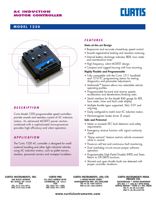
AC INDUCTIONMOTOR CONTROLLERD E S C R I P T I O NCurtis Model 1230 programmable speed controllers provide smooth and seamless control of AC induction motors. An advanced MOSFET power section,combined with a sophisticated micro-processor provides high efficiency and silent operation. A P P L I C A T I O NThe Curtis 1230 AC controller is designed for small material handling and other light industrial vehicles using AC induction motors, such as pallet movers, stackers, personnel carriers and sweeper/scrubbers.M O D E L 1230venueMt. Kisco, New York 10549 USACURTIS INSTRUMENTS, IF E A T U R E SState-of-the-art Design• Responsive and accurate closed-loop speed control.• Smooth regenerative braking and seamless reversing.• Internal battery discharge indicator (BDI), hour meterand maintenance timer.• High frequency, silent MOSFET design.• Compact and rugged housing with fuse mounting.Highly Flexible and Programmable• Fully compatible with the Curtis 1311 handheldand 1314 PC programming station for testing, diagnostics and parameter adjustments.• Multimode™ feature allows two selectable vehicle operating profiles.• Programmable forward and reverse speeds,acceleration and deceleration/braking rates.• Serial interface for the Model 840 gauge for BDI,hour meter, timer and fault code display • Multiple throttle types supported; 5k Ω, 0-5V and wig-wag.• Easily configured to match most AC induction motors.• Electromagnetic brake driver (2 amps).Safe and Protected• Meets or exceeds EEC fault detection and safetyrequirements.• Emergency reverse function with signal continuity check.• “Ramp restraint” feature restricts vehicle movementwhile in neutral.• Power-on self test and continuous fault monitoring.• Dual watchdog circuits ensure proper softwareoperation.• Programmable High Pedal Disable (HPD) and StaticReturn to Off (SRO) functions. • Shorted and open throttle faults are detected withproper controller shutdown.CURTIS INSTRUMENTS, INC.200 KISCO AVENUE MT. KISCO, NY 10549USATEL (914) 666-2971FAX (914) 666-2188CURTIS PMC235 EAST AIRWAY BLVD.LIVERMORE, CA 94551USATEL (925) 961-1088FAX (925) 961-1099CURTIS INSTRUMENTS, (UK) LTD.5 UPPER PRIORY STREETNORTHAMPTON NN1 2PT, ENGLANDTEL 44 (0) 1604-629755FAX 44 (0) 1604-629876CURTIS INSTRUMENTS INDIAPRIVATE LTD.DATTAPRASAD • AVANI APARTMENT APT . NO. 7 • 1206 B/7 APTE ROAD, SHIVAJI NAGAR • PUNE 411 004, INDIATEL 91 (0) 20-5531288 FAX 91 (0) 20-5539192O P T I O N SF E A T U R E S ...c o n t i n u e d• Internal clamps for inductive fly-back of coils.• Controller over-temperature protection.• Over and under-voltage protection.• Low battery charge LED warns operator of possiblebattery damage.• On-board fault code status LED with external LED driver for remote viewing of fault codes.Meets US and International RegulationsEN50081-2 emissions EN50082-2 immunity IEC 801-2 level 4 ESD VDE0117EN1175-1 safety UL recognizedIP 53 environmental protectionS Y S T EM AC CESS O R I E S• Internal main contactor.• Multiplexed control signals to reduce vehicle/tiller wiring.• Auxiliary outputs (2) for relays, horn or solenoid control.• CAN Bus communications for integration into distributedcontrol systems.The Curtis Model 840 LCD Multifunction display contains 8 large, easy to read characters to provide display of battery discharge (BDI), hour meter and error messages. Built-in backlight is also available.Model 1312 Tiller Multiplexer provides monitoring and control capability for up to12 analog or digital signals from operator controls on tiller. Each signal is trols osampled every 20 milliseconds for fast response.The Curtis Model 1311 Handheld Programmer provides a simple and intuitive interface to Curtis products for testing, diagnostics and parameter adjustments.D I ME N S I O N S : m mM O D E L C H A R TBattery Motor Current Motor Current Options Model No. Voltage 2 min. 1hour Main 1312 2 Aux. CAN (volts) (amps rms) (amps rms) Contactor Interface Outputs1230-2001 24 60 30 √ √ √ 1230-2002 24 60 30 1230-2101 24 90 40 √ √ √ 1230-2102 24 90 40 1230-2201 24 120 50 √ √ √ 1230-2202 24 120 501230-2301 24 150 60 √ √ 1230-2302 24 150 60 1230-2401 24 200 80 √ √ 1230-2402 24 200 80 1230-2403 24 200 80 √√Note: xx01 = Options; xx02 = No Options; xx03 = CANFor more information please contact your local CURTIS sales office.50.051.510.06.516.0M555.61.030.0146.0130.0148.0164.0Specifications subject to change without notice50110 REV C 11/03is a registered trademark of Curtis Instruments, Inc.©Curtis Instruments, Inc. 2003W A R R A N T YT wo Year Limited Warranty (see terms of sale for specifics).T Y P I C A L W I R I N G 1230-2X 02 (N O O P T I O N S )For further wiring information please contact your local CURTIS sales office.C O N N E C T O R D E T A I LJ2J3123413461121324J1。
固态高频焊管说明书_中文_v071230

.........使用说明保定三伊天星电气有限公司GGPXXX-0.X-H 型固态高频焊管设备目录第1章引言 (1)1.1 编写目的 (1)1.2 型号说明 (1)1.3 设备用途 (1)1.4 说明事项 (1)第2章使用条件 (3)2.1 使用环境 (3)2.2 冷却水要求 (3)2.3 电网要求 (4)第3章设备描述技术规范 (5)3.1 外型及结构 (5)3.2 规格型号 (11)3.3 电源连线要求 (12)3.4 开关整流柜与逆变柜动力连接线 (12)3.5 控制技术特点 (13)第4章电气原理 (15)4.1 三相全控桥式整流电路 (15)4.2 单相串联桥式逆变电路 (15)4.3 输出功率调节 (17)4.4 整流侧控制 (17)4.5 锁相环和相角锁定 (18)4.6 驱动电路及开关过程中寄生振荡的抑制 (18)第5章设备安装及使用说明 (21)5.1 设备安装 (21)5.2 使用说明 (21)第6章操作及注意事项 (26)6.1 操作程序 (26)6.2 注意事项 (26)第7章常用器件测量方法 (28)7.1 MOSFET管 (28)7.2 二极管 (28)7.3 电流霍尔元件 (28)7.4 可控硅 (28)第8章感应加热电源设备接零和接地要求 (29)8.1 设备的接零 (29)8.2 设备的接地 (29)8.3 高频机组生产线地线分布示意图 (30)第9章电气原理图及布线图 (31)附:固态焊管人机界面使用手册(V5.0版)11.1 编写目的本使用说明是针对用户操作人员和维护人员编写的,主要目的是为了用户能够正确使用、操作本设备,对设备的异常现象能简单处理,并能向本公司技术人员准确描述,以便本公司能及时准确地做好设备售后服务工作。
因此本使用说明主要描述一般性原理、外围电气结构及简单的调整和维护,不涉及详细的控制电路和深层次的控制原理,有关器件的参数及控制手段均不做详细解释,其原因是众所周知的。
海洋多功能1 2 3用户手册说明书
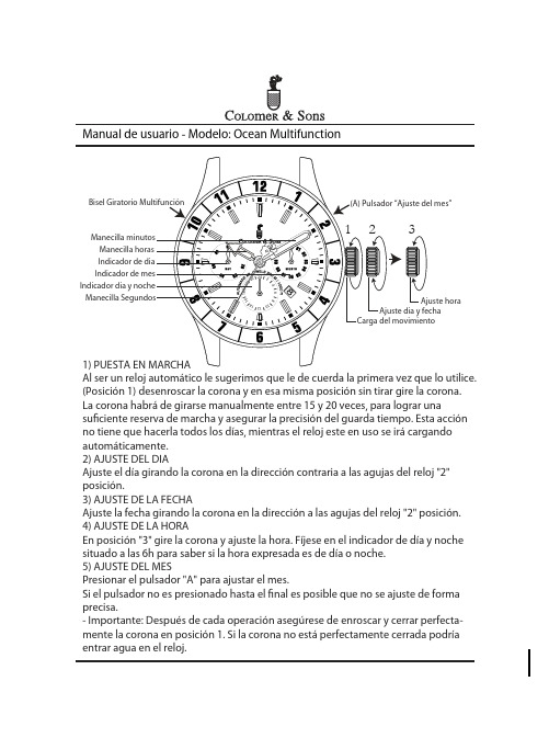
1) PUESTA EN MARCHAAl ser un reloj automático le sugerimos que le de cuerda la primera vez que lo utilice. (Posición 1) desenroscar la corona y en esa misma posición sin tirar gire la corona. La corona habrá de girarse manualmente entre 15 y 20 veces, para lograr unasuficiente reserva de marcha y asegurar la precisión del guarda tiempo. Esta acción no tiene que hacerla todos los días, mientras el reloj este en uso se irá cargando automáticamente.2) AJUSTE DEL DIAAjuste el día girando la corona en la dirección contraria a las agujas del reloj "2" posición.3) AJUSTE DE LA FECHAAjuste la fecha girando la corona en la dirección a las agujas del reloj "2" posición.4) AJUSTE DE LA HORAEn posición "3" gire la corona y ajuste la hora. Fíjese en el indicador de día y noche situado a las 6h para saber si la hora expresada es de día o noche.5) AJUSTE DEL MESPresionar el pulsador "A" para ajustar el mes.Si el pulsador no es presionado hasta el final es posible que no se ajuste de forma precisa.- Importante: Después de cada operación asegúrese de enroscar y cerrar perfecta-mente la corona en posición 1. Si la corona no está perfectamente cerrada podría entrar agua en el reloj.El bisel giratorio se puede utilizar de diversas formas:Opción 1: Se puede usar para ajustar una segunda zona horaria.Opción 2: Se puede usar para marcar el punto en el que se ha realizado unainmersión en el agua cuando se bucea.Aquí expresamos un ejemplo de uso de doble zona horaria:1. (C) El dial central indica la hora local.2. (D) El bisel giratorio indica la segunda zona horaria “Casa”Ejemplo: Cuando deseo saber la hora en Madrid mientras estoy de viaje en Hong Kong y la hora local son las 2:00 PM - Es necesario conocer de antemano la diferencia de horas entre las dos ciudades que queremos ajustar. En nuestro ejemplo, Hong Kong tiene + 6 horas de diferencia en horario de verano y + 7 hora durante el invierno con respecto a Madrid.Por lo tanto 2:00 PM en Hong Kong serán las 7 AM en Madrid teniendo en cuenta el uso horario de invierno.*(D) Girar el bisel hasta las 7 AM horas (uso horario de invierno).Ahora ambas zonas horarias están ajustadas y no requiere que se modifique la posición del bisel mientras usted este en Hong Kong, cuando la manecilla de horas se desplace a las 3 PM hora local, la hora en el bisel indicará automáticamente la hora de Madrid en este caso 8 AM.(D) Segunda zona horaria “Casa”Bisel Giratorio Multifunción。
PC1230中文说明书

1.2 用户.
该手册针对终端用户。在不确定的情况下必须还要咨询技术专家。
2.安全
2.1 正确用法
便携式电源只能用于光伏系统,给铅酸蓄电池或者胶体电池充电,并向常规负 载提供交/直流电。
2.2 错误用法
除了太阳能电池外,产品不能接入别的电源如电网、柴油发电机或者风力发电 机。不要连接任何损坏或者不良的测试设备。
●●○○○
绿灯 1
常亮
绿灯 2
常亮
含义 正在充电 低压保护 蓄电池 100%电量 蓄电池 75%电量 蓄电池 50%电量 蓄电池 25%电量 直流输出正常 交流输出正常
4.安装
4.1 准备线材
太阳能输入采用铜软线,导线截面积不得小于 2.5 mm2 直流输出使用铜软线,导线截面积不得小于 2.5 mm2 交流输出使用铜软线,导线截面积不得小于 1 mm2
保期,因此我们无法在整个产品生命周期内提供免费保修。希望客户能够理解。
光伏系统中的所有配件,必须按照相关供应商提供的规格书进行例行检查,最
少一年一次。
确保通风
检查电缆是否松动
检查所有的电缆连接是安全的
如有必要将所有螺丝拧紧
端子是否腐蚀
设备含有一个保险丝附件。如果由于误操作导致设备内保险丝熔断,请由专业
Version 1.0
March 22, 2011
安装操作指南
便携式电源 PC1230
1
Version 1.0
1. 关于该手册
以下操作指南属于产品的一部分。 使用前请仔细阅读指南 请保存好该手册 如果产品转交给别人使用也请将手册一起转交给新的用户。
GPS1230系统简易操作手册(图形)-GSM

GPS1200系统简易参考手册目录一.RX1200简介及图标说明 (1)1、RX1200布局 (1)2、状态栏 (1)3、菜单树 (6)二.系统架设 (7)三.静态测量野外操作流程 (10)四.流动站配置集的建立 (13)五.参考站配置集的建立 (18)六.动态参考站的野外工作流程 (25)七.动态流动站的野外工作流程 (27)八.仪器上坐标系统的建立 (30)九.放样操作流程(ASCII输入) (35)一.RX1200简介及图标说明1.RX1200布局2.状态栏a---功能键F1-F6b---字母键c---大小写键d---热键F7-F12e---空格上挡键f----回车键g---光标移动键h---退格,退出,用户定义,程序键i----数字键a 时间b 标题c 主菜单d 屏幕区e 信息栏f 图标g 退出h 子菜单i 上挡键j 大小写键k F1-F6键定位状态可视卫星数量使用卫星a 定位状态b 可视卫星数量c 使用卫星d 实时设备和状态e 定位模式f 快速编码g 线/面h CF 卡/内置内存i 电量 j 上挡键实时设备和状态参考站流动站GRX1200定位模式快速编码线/面CF卡和内置内存电量上挡键3. 菜单树注意:1200系统为专业测量人员而设计,整个系统操作灵活。
对于同一个操作界面有多种的进入方法。
主菜单1.测量2.程序3.管理4.转换5.配置6.工具二.系统架设下图为参考站两个三脚架模式设备安装连线建议方案注:图中为欧洲国家建议配置,在中国区的配置以实际合同配置为准。
下表为中国区参考站配置各部件详解下图为流动站背包模式设备安装连线建议方案注:图中为欧洲国家建议配置,在中国区的配置以实际合同配置为准。
下表为中国区流动站配置各部件详解三.静态测量野外操作流程1,主菜单步骤:按PROG/ON 开机2,测量前必要的参数检查界面步骤:a 、作业表示我们以后所测的点都存储在这个作业中(新建作业的步骤看后面)b 、坐标系 表示我们在做静态的时候都要用WGS 1984坐标系统,因为这是全球通用的坐标系统, GPS 所采集的坐标都是WGS 1984坐标系统,回来后在软件中经过投影转换到我们要用的坐标系统(可按F6(坐标)看到仪器里存在的坐标系统,包括我们自己建立的)c 、编码块 这是特地为一些要测图的用户准备的,这里我们不用d 、配置集 PP Static (5sec )是仪器缺省的静态配置集,我们直接选择它就好了e 、天线 表示我们的仪器是架在三角架上的 设置好后,按F1(继续)进入下一页面3,开始测量步骤:a 、点号 输入我们要测的点的点号,可按自己的习惯编写b 、天线高 输入用量高尺读出来的高度,读量高尺的时候读到白线c 、几何精度因子 表示空间卫星位置的好坏设置好后,按F1(上站/测量),开始记录数据4,结束测量步骤:Msd PP Obs 行表示我们所采集的历元数,根据控制点的等级不同,所采集的历元数也相应不同,可在相关规范上查到,如果控制要求不是很高,一般我们看时间,等到开机半个小时左右就可以了等到记录了足够的历元,按F1(停止),结束采集,到下一页面5,保存测量数据按F1(保存),这样我们采集的数据就存储到我们所选的作业里了6,A 退出我们可以看到,又回到测量页面,点号自动累加,按ESC 键再按F6退到上一页面,再按ESC 键退回到主菜单也可以按SHIFT 键,再按F6,直接退回主菜单按USER+PROG 关机,这时可以收好仪器到下一个点了注意:在做静态之前,一定要进行网形设计,网形的好坏会影响到成果的精度,有关控制网设计的知识请参阅有关书籍,另外在做静态的时候,必须联测已有的控制点,而且要三个或三个以上,因为在后处理软件中坐标转换的时候,要有三个点或三个以上才能用经典三维法进行转换坐标转换:是为了将GPS 的WGS 1984坐标系统转换成我们要用的坐标系统,如北京54坐标系统四.流动站配置集的建立1,主菜单进入管理模块开机(PROG/ON ),将光标(方框)移到3管理,按F1进入,也可以直接按数字键3进入,或用红笔点击屏幕进入。
ASK Proxima C130 说明书
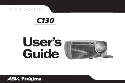
> >> >> >>User’sGuide附带的光盘上有=^ÇçÄÉ=^ÅêçÄ~í=éÇÑ=格式的整本《使用者指南》,包括以下各种语言版本:英文、法文、德文、意大利文、挪威文、葡萄牙文、西班牙文、俄文、日文、韩文、繁体中文和简体中文。
请在使用投影机以前,先阅读这些说明。
=合格声明制造商:fåcçÅìë=`çêéçê~íáçåI=OTTMM_=pt=m~êâï~ó=^îÉK=táäëçåîáääÉI=lêÉÖçå=VTMTM= rp^欧洲办事处:píê~ïáåëâóä~~å=RURI=NMTT=uu=^ãëíÉêÇ~ãI=qÜÉ=kÉíÜÉêä~åÇë我们承担所有责任,在此声明:投影机符合下列规程和标准:bj`=规程=UVLPPSLbb`,VPLSULbb`=修订条文bj`Wbk=RRMOO=bk=RRMOQbk=SNMMMJPJObk=SNMMMJPJP低压规程=TPLOPLbb`,VPLSULbb`=修订条文安全性:bk=SMVRM:=OMMM=OMMQ=年=O=月商标^ééäÉ、j~ÅáåíçëÜ=和=mçïÉê_ççâ=是=^ééäÉ=`çãéìíÉêI=fåÅK=的商标或注册商标。
三一操作手册

1-3
除满足作业人员基本资格要求外(见表1-1),技术专家必须满足以下额外资格 要求(表1-6)。
表1-6 技术专家资质
1
项目
要求
安
培训
进行过相关的现行法律规程和事故预防规程的培训;
全
进行过产品相关知识培训。
能力
具有能够检验操作规程的能力;
具有对作业人员工作进行指导的能力。
1.2 作业现场安全
机组安装运行后,对周边环境具有一定的影响,会对误闯入该区域的人员或 不熟悉设备的人员造成危险。因此业主、经营者有义务在机组周围安置额外的警告 牌,以涵盖不涉及机组制造商安全信息。
换算关系 1 in=3.937 m 1 ft=0.3281 m 1 gal=0.2642 L 1 qt=1.057 L 1 yd3=1.308 m3 1 lb=2.205 kg 1 Kgf=0.10197 N 1 lbf=0.2248 N 1 kgf·m=0.10197 N·m 1 lbf·ft=0.7375 N·m 1 kgf/cm2=10.197 Mpa 1 bar=0.1 Mpa 1 PS=1.36 KW 1 HP=1.341 KW 1 °F=1.8 ℃+32 1 mph=0.6214 Km/h 1 Rpm=1 min-1 1 gpm=0.2642 L/min 1 cc/rev=1 mL/rev
1.1.4 技术专家资质及要求 ……………………………………… 1-3
1.2 作业现场安全 ……………………………………………… 1-4
2操作环境… ………………………………………………… 2-1
3操作方式 ………………………………………………… 3-1 3.1 按键/开关 …………………………………………………… 3-1 3.1.1 塔底控制柜的按键/开关 …………………………………… 3-1 3.1.2 机舱控制柜的按键/开关 …………………………………… 3-2 3.1.3 紧急停止键 ………………………………………………… 3-3 3.1.4 运行模式开关 ……………………………………………… 3-4 3.1.5 手动停止键 ………………………………………………… 3-5 3.1.6 手动安全停止键 …………………………………………… 3-5 3.2 触摸屏 ……………………………………………………… 3-6 3.2.1 登录界面 …………………………………………………… 3-6 3.2.2 操作界面 …………………………………………………… 3-7 3.3 远程监控软件 ……………………………………………… 3-8
PCIe1230-1232使用说明书-20150113
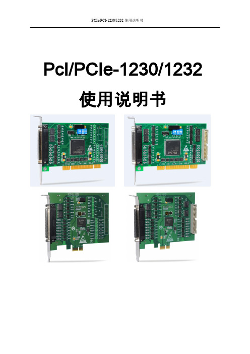
PCIe/PCI-1230/1232使用说明书PcI/PCIe-1230/1232 使用说明书版权声明本文档所有权归深圳市升立德科技有限公司(后面简称“升立德”)所有;升立德具有本产品及其软件的专利权、版权和其它知识产权。
未经授权,任何单位和个人不得直接或者间接地复制、制造、加工、使用本产品及其相关部分。
升立德保留在不事先通知的情况下,修改本手册中的产品和产品规格等文件的权力升立德全力维护本文档的正确性,但不承担由于本文档错误或使用本产品不当,所造成直接的、间接的、特殊的、附带的或相应产生的损失或责任。
2目录版权声明 (2)1概述 (1)1.1特点 (1)1.2性能和指标 (1)1.3PCI E-1230结构布局 (1)2引脚描述 (2)2.1CN1连接器 (2)2.2CN2连接器 (2)3拨码开关设置 (3)3.1SW1 (3)3.2SW2 (3)4输入输出说明 (4)4.1光隔离输入 (4)4.2光隔离输出 (4)4.3DO与继电器的接法 (5)5函数库使用方法 (6)6编程指南 (7)7驱动安装 (9)8硬件安装及调试 (11)9附录 (12)9.1端子板结构图 (12)9.2DIN-8D驱动板 (13)10故障处理 (15)11修订记录 (16)1概述PCIe-1230/1232是基于PCI Express协议的光隔离道输入输出控制卡,用户可设置板ID号。
1.1 特点PCIe-1230:16路光隔离输入通道(无极性),16路光隔离输出;PCIe-1232:32路光隔离输入通道(无极性),32路光隔离输出具有较高的输出驱动能力光隔离输入输出采用DB37连接器可配置板ID号1.2 性能和指标光隔离输入通道输入电阻4.7K @1/4W光隔离输入逻辑高:3V~24V ,逻辑低为:0~2.4V光隔离输出通道采用达林顿管集电极开路输出,集电极开路电压5V~35V(DC)50mA反向电流输出隔离电压3750Vrms通过EMC认证,符合EN61000-6-4:2007+A1:2011, EN61000-6-2:2005测试标准。
中文1232交流控制器技巧使用
科蒂斯仪器科蒂斯仪器((中国中国))有限公司有限公司 www.curtisinstruments.com 1232 1234 1236 1238 交流交流电机电机电机控制器控制器 2011年3月版-OEM 安全指南 在开始操作前务必仔细阅读本手册!! ! 在开始操作前务必仔细阅读本手册 在开始操作前务必仔细阅读本手册调试和使用的人员。
本手册包括了保证人身安全与保护本产品应遵守的注意事项。
这些注意事项在手册中以三角形警告图标加以突出。
免责声明免责声明 我们已核对过本手册的内容。
由于差错难以完全避免,我们不能保证和所描述的产品完全一致,我们会检查经常手册的内容,并在后续的编辑中进行必要的更正。
技术数据如有改动,恕不另行通知。
- 2 - 目录 - 3 - 目录....................................................概述.................................................1. 简介................................................应用................................................特性................................................相关标准..............................................系统配件..............................................物料搬运车..............................................2. 基础.................................................3.控制器...............................................机械安装要求............................................电气连接要求............................................典型接线图.............................................A. 系列仪表.......................................配840系列仪表......................................配enGageB. 技术规格..............................................可编程参数.............................................手持编程器...........................................1311加速器...............................................电机................................................电池................................................检测.................................................4. 4.1 菜单检测............................................加速器输入检测......................................4.1.1 4.1.2 方向输入检测.......................................主接触器检测.......................................4.1.3 万用表检测...........................................4.2 调试.................................................5. 基本参数设置..........................................5.1 电机参数设置.......................................5.1.1 限流参数设置.......................................5.1.2 电池参数设置.......................................5.1.3 主接触器参数设置.....................................5.1.4 电磁刹车参数设置.....................................5.1.5 加速器参数设置......................................5.1.6 刹车加速器参数设置....................................5.1.7 当前故障检查.......................................5.1.8 紧急方向参数设置.....................................5.1.9 互锁刹车参数设置.....................................5.1.10 控制模式参数设置.....................................5.1.11 泵电机参数设置......................................5.1.12 - 3 - 5.2 控制器和电机匹配........................................电机匹配..........................................5.2.1 最大牵引力测试......................................5.2.2 5.2.3 拐点测试..........................................车速设置..........................................5.2.4 测量.................................................6. 限流参数设置..........................................6.1 测量前期准备..........................................6.2 测量和记录...........................................6.3 附录..................................................1.参数菜单(表3).........................................2.监控菜单(表4).........................................故障代码(表5).........................................3. 4. 故障排查.............................................注意事项.............................................5. - 4 - 概述 1. 简介 科蒂斯1232/34/36/38电机速度控制器,通过先进的控制软件保证了电机在不同的模式下,都能平稳运行,包括全速和大扭矩状态下的再生制动,零速以及扭矩控制,专有的输入/输出端口及软件,保证了控制器对电磁制动和液压系统控制的经济性和高效率。
sx1231用户向导手册
本手册为SX1231提供的daemon 板的安装及使用说明文档,原文为英文文档《SX1231SKB User's Guide》,仅供参考;2.2 安装(要确保在线安装)1:在CD-ROM 中打开驱动盘,安装sx1231starterkitsetup.exe.2: 如果设备提供说明书,那么请参考insert sheet(说明书)的介绍,并且从其提供的网络连接中下载最新版本的软件。
3:按照屏幕上的提示完成安装,安装过程要确保在线安装,这样当安装程序发现你的计算机上没有FTDI 驱动时会自动安装,同时自动安装.NET Framework3.54: 通过USB 桥连接SX1231SKB板和PC ,此时USB桥和SX1231 均由USB 供电5:启动SX1231SKB6:在文件菜单中或者在工具条中点击connect 连接7:此时SX1231SKB 已经安装完毕,并准备好被使用!问题:本人在第一次安装的时候,由于计算机未连入外网,安装成功后,启动时显示无法加载frdi.dll 因为没有安装FTDI 驱动!!如图示:且页面是灰色!问题解决:在线安装一切ok!2.3概述发送和接收的状态由USB 桥板上的一对led灯显示出来3:SX1231 快速启动向导1:通过USB 连接SX1231到PC 上,连接上后桥接板上的USB电源等会点亮2:运行SX1231 用户接口软件 SX1231SKB3:SX1231SKB 会自动连接到用户接口软件上,如果没有点击界面顶部的连接按钮,4:一旦连接成功,SX1231SKB 会显示当上电时默认的SX1231的寄存器配置,如果连接不成功则界面是灰色的,且会在status bar(状态栏部分)提示出错信息!4:SX1231SKB软件描述4.2 Menu ToolBar工具栏包含四组菜单:文件功能工具帮助4.2.1 File Menu 文件菜单1:Connect/Disconnect: 建立或断开SX1231通过USB 桥到PC的连接;这一功能也可以通过点击窗口上的功能按钮实现。
三星智能家居DONGLE用户手册HD39J1230GW说明书

What is SMART HOME DONGLE? (3)Application of SMART HOME DONGLE (3)Installation of SMART HOME DONGLE (4)Installing SMART HOME DONGLE (4)Installation of Smart Home App (4)Setting the network (5)Specification of wired/wireless router for Samsung SMART HOME donlge (6)Downloading Samsung Smart Home App (7)Registering Samsung account (7)Downloading Samsung Smart Home App (8)Registering the product ........................................................... 9Specification . (17)Open Source Announcement (17)Safety information (18)Troubleshooting (21)Contents2Installation of SMART HOME DONGLEInstalling SMART HOME DONGLE• Install the dongle at the given position of each Samsung Smart READY appliance.• Refer to the appropriate manual of Samsung Smart READY appliances for the installation position.• Download a manual of each appliance at www. and refer to it.• Refer to an application manual or a user manual of each Smart READY appliance for using the application.Installation of Smart Home App[Setting the network]Connect the wired/wireless router to the SMART HOME DONGLE wirelessly.[Registering Smart Home Service] Register the service using Smart Home appon your Smartphone.4Samsung account login screen(iphone)ab 12d c32ac3bd654e8910f1112g h13Safety informationThese safety precautions are for owner’s safety and preventions of property damage. Therefore, please read this manual thoroughly before using your product.The manufacturer is not responsible for the injury or property damage occurred by not following the safety information.This product is for Samsung Smart READY appliances, and it will not work on other devices.• If the product is getting heat, stop using it.–If your skin gets in contact with the heating product for a long while, a low-temperature burn such as red spots, pigmentation, etc. may occur.• Do not put the product near or in a heater(stove, microwave, etc.), a cooking utensil or a high pressure vessel.–It may supply heat to the product or may cause fire.• Do not drop the product or give external shocks to the product.–Do not put or store the product on a slant.–If the product is dropped, it may get damage and malfunction.• Be careful that children, toddlers or pets do not suck or bite the product.–It may cause damage to the product.18• Do not attempt to repair, disassemble, or modify the product yourself.–If a user attempts to repair, disassemble or modify the product, the user cannot have free repair service, and must contact Samsung Electronics' service center for the repair.• Be careful when cleaning the product.–Clean the product with a soft cloth.–Do not use harsh chemicals or detergent for cleaning the product. It may cause productdiscoloration or corrosion.• This equipment is a EMC device for home use (B grade), and it is intended primarily for using at home and it can be used in all area.20TroubleshootingDownload Samsung Smart Home App cannot be searched on Play store, GALAXY Apps or iPhoneApp Store.Samsung Smart Home app supports android operating system 4.0(ICS) or higher. ForiPhone, iOS 7 or higher supports the App.Sign in Samsung account cannot be accessed.Check your ID and password on Samsung account screen.21Connection After installing Samsung Smart Home App, the Samsung Smart READY appliance cannot be connected to the App.Unplug the Smart READY appliance and plug in it again, and then set Samsung SmartHome app and Wi-Fi again according to the guidance in the manual.The failure message appears when the device is being added.The failure might be temporary due to the distance between the wired or wireless routerand the air conditioner or other problems. Try it again after a while.Unplug the SMART HOME doing and pulg in it again. Try it again after a while. Function The control function of Samsung Smart Home App does not work.• Check whether the Samsung Smart READY appliance is connected to the wired orwireless router correctly.• Check whether the wired or wireless router is connected to the Internet correctly.22Memo。
MD1230操作手册-以太部分
MD1230B基本操作MD1230B基本操作 (1)一、开机准备 (2)二、进入主应用程序 (4)2.1 设置发送数据流 (6)2.2 通过计数器进行流量统计 (8)2.3 捕获和协议解码分析 (9)2.4 延迟、PING和包抖动测试功能 (10)2.5 RFC2544自动性能测试 (11)一、开机准备MD1230B开机后,首先启动Win会自动进入到选择菜单(Selector),界面如下:Main Application“Selector”画面下连续15秒没有操作将自动进入“Main Application”主应用程序。
如果选择“Setup Utility”,则进入设置页面。
如下图:IP地址有两个,一个是Windows IP,即主机的IP地址,可与外部连接。
另一个是Unit IP,即测试单元的IP地址。
必须将Windows IP与Unit IP设置在同一个网段中,主应用程序才能对测试单元进行操作!二、进入主应用程序主应用程序启动后,MD1230B进入如图一界面:图一、主应用程序画面该画面中左侧出现的内容与仪表安装的测试模块有关,在本例中,MD1230B 安装的是MU120111A 10/100M模块(安装在UINT1:3,指Unit1的第三个槽位)和MU120112A GbE模块(安装在UINT1:4)。
这里的Unit就是指机器的测试单元,与前一节提到的Unit IP的Unit是同一个。
将鼠标移动到Unit1处按右键,可弹出Unit设置菜单,可对Unit进行设置。
具体的设置内容请参考原版操作手册。
图一画面左侧的Port 1,Port 2……是指测试模块上的测试端口,图中的测试端口图标有橙色的“”,也有灰色的“”,两种颜色和符号代表的意义不相同,橙色符号表示该端口被当前用户占用,灰色符号表示该端口尚未被占用,其它用户可以使用。
橙色符号在连接建立起来后会变成绿色符号“”。
将鼠标移动到Port 1处按右键,可弹出Port设置菜单,可对Port进行设置。
- 1、下载文档前请自行甄别文档内容的完整性,平台不提供额外的编辑、内容补充、找答案等附加服务。
- 2、"仅部分预览"的文档,不可在线预览部分如存在完整性等问题,可反馈申请退款(可完整预览的文档不适用该条件!)。
- 3、如文档侵犯您的权益,请联系客服反馈,我们会尽快为您处理(人工客服工作时间:9:00-18:30)。
销售热线: 010-65260683 010-65230684
地址:
北京市中粮广场 B 座 906
邮编:100005
客服热线: 0512-66673079 0512-66673059
地址:
苏州市金山路 86 号
邮编:215129
目
录
物料搬运车作业台 --------------------------- 2 基础篇 ------------------------------------- 3
逻辑部分插件:24 芯 Molex Mini-Fit Jr., P/N 39-01-2245。 6 芯 Molex Mini-Fit Jr., P/N 39-01-2065。 4 芯 Molex Mini-Fit Jr., P/N 39-01-2045。
功率部分插件:M5 接线片
3
交流电机
电机是将电池电能转换成机械能,驱动电动车车轮旋转的部件。 使用 n 电机的周围应保持清洁干燥,其内外部不应放置其它物件; n 严禁与强磁性物体并存; n 输入电压等级需确保正确; n 使用中若发现电机有异常气味,应立即停车检查; n 电机和控制器之间的走线应尽可能短; n 严禁过载使用; n 电机在运行如发生漏电,转速突然下降,发生剧烈振动,有异常大的声响,过热冒烟,
调试篇 ------------------------------------ 19
测量篇 ------------------------------------ 22 注意事项 ---------------------------------- 23
1
物料搬运车作业台
`
表1
序号 1 2 3 4 5 6 7 8 9
CURTIS
`
科蒂斯
交流电机控制器使用
说明书
1230 系列
1230 系列
交流控制器 使用说明书
尊敬的用户:
您好! 欢迎您使用 CURTIS 控制器。为了您在使用我们的产品前,能够更好的了解 我们的产品,请您仔细的阅读本说明书,如有其它疑问,请随时与我们联系。
科蒂斯(中国)
交流电机控制器 ---------------------------- 3 交流电机 --------------------------------- 4 电池 ----------------------------------------- 4 标准连线图 ------------------------------------ 5 技术规格 -------------------------------------- 5 参数菜单 --------------------------------- 6 监控菜单 -------------------------------- 13 诊断与故障指南 --------------------------- 14 检测篇 ------------------------------------ 16
名称 电量表
喇叭 电池 控制器 电机 主接触器 保险丝 应急开关 手柄
功
能
电池状态指示用,840/906 表较为适用
警示用
提供车用电能,电压/安时数
控制电机转速以及各种信号处理,电压/电流
驱动代步车车轮旋转,电压/电流
车辆安全保护,电压/电流
电机过流保护,电流
车辆安全保护
调节车速
2
基础篇
交流电机控制器
规 格 序号
名称
规格
24V 16KHZ
11 电磁刹驱动电流 2A 12 加速器控制信号 2/3 线,0-5KΩ/0-5V
>500AC
>7.5 为高
13 速度控制类型 14 工作环境温度
额定 电压 (伏)
24 24 24 24 24 24 24 24 24 24 24
选型
2 分钟
60 60 90 90 120 120 150 150 200 200时
30 30 40 40 50 50 60 60 80 80 80
接线 l 电机、电池与控制器之间的连线尽可能短,且平行; l 小电流接线应远离大电流接线,如须则以正交十字形穿越; l 所有开关须处于断开位置,禁止带电操作; l 主保险丝与控制回路保险丝不可少,且须与控制器最大电流值匹配。 注:交换控制器 U、V、W 的任意两项,可改变车辆的运行方向!
或电器接点打火冒烟,应立即断电,停机检查; n 要经常检查电机是否有过热现象; n 要经常检查电机接线接点螺丝,有无松动、打火冒烟、绝缘老化现象;
电池
l 不在过载、高湿度或大坡度等情况下使用; l 保持蓄电池散热部分的畅通,不可在太阳光下暴晒; l 不可将新旧电池混用; l 若蓄电池使用时间超过 4 年,则需要更换; l 充电时,切勿将电池极性接反,否则可能造成电池报
4
标准接线图
请在接线前翻阅第 18 页 注意事项!
技术规格
序号 1 2 3 4 5 6 7 8 9 10 11
名称 正常输入电压 PWM 工作频率 与散热器绝缘强度 逻辑端口输入电压 KSI 输入电流 逻辑端输入电流 最大输出频率 正常相间电压 LED 状态灯驱动电流 LED 电池灯驱动电流 相关标准
废; l 免维护电池不使用时需定期充电,一般不要超过一个月; l 开放型液体铅酸电池不能缺水,一般二至三月需加水维护; l 拆除蓄电池时,应先拆除负端,以免正端与车体某个部分接触短路。 l 取下电池充电时,不要用湿手或钥匙等金属接触电极两端,以免烧伤。 l 充电时,充电指示灯显示满电时不要立即停止充电,应再浮充 2-3 小时。 l 充电时要用配套的专用充电器,不要混用充电器。
先进的可编程带微处理器的 CURTIS 交流电机速度控制器,它能提供平稳、安静、低 成本高效的电机速度和扭矩控制。完全符合欧洲和美国的各种安全标准。
安装布局 l 通风性和散热性好; l 位置清洁干净; l 靠近电机和电池; l 手持单元易插拔;
型号
1230-2001 1230-2002 1230-2101 1230-2102 1230-2201 1230-2102 1230-2301 1230-2302 1230-2401 1230-2402 1230-2403
