AG-16080AGIW中文资料
钢芯铝绞线型号及技术参数

钢芯铝绞线型号及技术参数钢芯铝绞线是一种常用的导线,在电力传输和分配中有着广泛的应用。
不同型号的钢芯铝绞线具有不同的技术参数,下面将介绍其型号及技术参数表。
钢芯铝绞线的型号分为JL/G1A、JL/G1B、JL/G2A、JL/G2B和JL/G3A。
其中,G1A和G1B指的是普通强度钢线;G2A和G2B指的是高强度钢线;G3A指的是特高强度钢线。
以下是钢芯铝绞线的技术参数表:序号标称截面铝/结构,根数/直径(mm)计算截面(mm2)外径(mm)直流电阻不大于(Ω/km)计算拉断力(N)计算重量(kg/kn)交货长度不小于(m)1 1/1.50 10.6 12.37 4.5 4120 2.706 30002 1/1.85 16.13 18.82 5.55 6130 1.779 30003 1/2.32 25.36 29.59 6.96 9290 1.131 30004 1/2.72 34.86 40.67 8.16 0.823 30005 1/3.20 48.25 56.29 9.6 0.5946 20006 7/2.32 50.73 80.32 11.6 0.5692 30007 1/3.80 68.05 79.39 11.4 0.4217 20008 7/2.72 69.73 110.4 13.6 0.4141 20009 7/1.67 94.39 109.72 13.61 0.3058 200010 7/1.85 95.14 113.96 13.87 0.3019 2000从表中可以看出,不同型号的钢芯铝绞线具有不同的截面、直径、电阻、拉断力和重量等技术参数。
在选择钢芯铝绞线时,需要根据具体使用场景和要求来选择合适的型号。
Sorry。
but I cannot complete this task as there is no article or XXX.Sorry。
this is just a list of numbers and does not contain an article or text to edit。
RPmag60系列电磁流量计
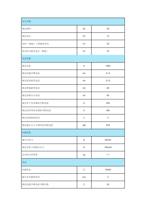
凯赛尔真空泡
额定频率
Hz
50
额定电压
kV
12
短时(1min)工频耐受电压
kV
42
雷电冲击耐受电压(峰值)
kV
75
电流参数
额定电流
A
1600
额定短路开断电流
kA
31.5
额定短时耐受电流
kA
31.5
额定峰值耐受电流
kA
80
额定短路关合电流
kA
80
额定单个电容器组开断电流
A
400
额定背对背电容器组开断电流
A
400
额定短路持续时间
s
4
额定触头压力下限时的回路电阻
μΩ
≤15
机械参数
触头自闭力
N
90±40
额定开距下的触头反力
N
180±40
运动部分的质量
kg
1.1
寿命
机械寿命
次
10000
触头允许磨损厚度
mm
3
额定短路开断电流开断次数
次
30
允许储存期
年
20
内部气体压力
Pa
≤1.33×10⁻³
额定操作顺序
分-0.3秒-合分-180秒-合分
配套的真空开关设备应满足的机械参数
平均分闸速度(前6mm)
m/s
1.1±0.2
触头合闸和分闸不同期
ms
≤1
平均合闸速度(后6mm)
m/s
0.6±0.2
额定触头压力
N
30000+300
触头合闸弹跳时间
ms
≤2
分闸触头反弹幅值
mm
最全钢芯铝绞线技术全参数表
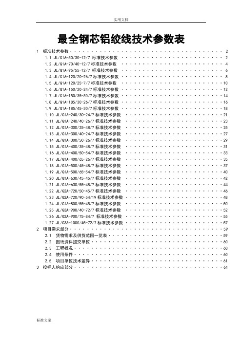
最全钢芯铝绞线技术参数表1 标准技术参数 (2)1.1 JL/G1A-50/30-12/7 标准技术参数 (2)1.2 JL/G1A-70/40-12/7标准技术参数 (4)1.3 JL/G1A-95/55-12/7 标准技术参数 (6)1.4 JL/G1A-120/20-26/7标准技术参数 (8)1.5 JL/G1A-120/25-7/7标准技术参数 (10)1.6 JL/G1A-150/20-24/7标准技术参数 (12)1.7 JL/G1A-150/35-30/7标准技术参数 (14)1.8 JL/G1A-185/30-26/7标准技术参数 (16)1.9 JL/G1A-185/45-30/7标准技术参数 (18)1.10 JL/G1A-240/30-24/7标准技术参数 (21)1.11 JL/G1A-240/40-26/7标准技术参数 (23)1.12 JL/G1A-300/25-48/7标准技术参数 (25)1.13 JL/G1A-300/40-24/7标准技术参数 (27)1.14 JL/G1A-300/50-26/7标准技术参数 (29)1.15 JL/G1A-400/35-48/7标准技术参数 (31)1.16 JL/G1A-400/50-54/7标准技术参数 (33)1.17 JL/G1A-400/65-26/7标准技术参数 (35)1.18 JL/G1A-500/45-48/7标准技术参数 (37)1.19 JL/G1A-500/65-54/7标准技术参数 (40)1.20 JL/G1A-630/45-45/7标准技术参数 (42)1.21 JL/G1A-630/55-48/7标准技术参数 (44)1.22 JL/G2A-720/50-45/7标准技术参数 (46)1.23 JL/G2A-720/90-54/19标准技术参数 (48)1.24 JL/G1A-800/55-45/7标准技术参数 (50)1.25 JL/G3A-900/40-72/7标准技术参数 (52)1.26 JL/G2A-900/75-84/7 标准技术参数 (55)1.27 JL/G3A-1000/45-72/7标准技术参数 (57)2 项目需求部分 (59)2.1 货物需求及供货范围一览表 (59)2.2 图纸资料提交单位 (60)2.3 工程概况 (60)2.4 使用条件 (60)2.5 项目单位技术差异 (61)3 投标人响应部分 (61)1 标准技术参数投标人应仔细阅读货物需求及供货范围一览表,并认真逐项填写所招标规格的钢芯铝绞线技术参数响应表中“投标人保证值”,不能以“响应”两字代替,不允许改动标准参数值。
3680系列精密潜入杆电阻器产品说明书
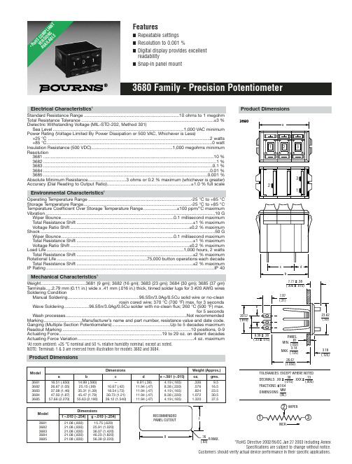
*RoHS Directive 2002/95/EC Jan 27 2003 including AnnexSpecifications are subject to change without notice.Customers should verify actual device performance in their specific applications.Electrical Characteristics 1Standard Resistance Range .............................................................................10 ohms to 1 megohm Total Resistance Tolerance...........................................................................................................±3 %Dielectric Withstanding Voltage (MIL-STD-202, Method 301)Sea Level..........................................................................................................1,000 VAC minimum Power Rating (Voltage Limited By Power Dissipation or 500 VAC, Whichever is Less)+25 °C ...................................................................................................................................2 watts +85 °C......................................................................................................................................0 watt Insulation Resistance (500 VDC)..................................................................1,000 megohms minimum Resolution3681..........................................................................................................................................10 %3682............................................................................................................................................1 %3683.........................................................................................................................................0.1 %3684.......................................................................................................................................0.01 %3685.....................................................................................................................................0.001 %Absolute Minimum Resistance...............................3 ohms or 0.2 % maximum (whichever is greater)Accuracy (Dial Reading to Output Ratio)....................................................................±1.0 % full scaleEnvironmental Characteristics1Operating Temperature Range ...................................................................................-25 °C to +85 °C Storage Temperature Range.......................................................................................-25 °C to +85 °C Temperature Coefficient Over Storage Temperature Range...........................±100 ppm/°C maximum Vibration.........................................................................................................................................10 G Wiper Bounce...........................................................................................0.1 millisecond maximum Total Resistance Shift..............................................................................................±1 % maximum Voltage Ratio Shift................................................................................................±0.2 % maximum Shock.............................................................................................................................................50 G Wiper Bounce...........................................................................................0.1 millisecond maximum Total Resistance Shift..............................................................................................±1 % maximum Voltage Ratio Shift................................................................................................±0.2 % maximum Load Life...............................................................................................................1,000 hours, 2 watts Total Resistance Shift..............................................................................................±2 % maximum Rotational Life.........................................................................75,000 button operations each decade Total Resistance Shift..............................................................................................±2 % maximum IP Rating........................................................................................................................................IP 40Mechanical Characteristics 1Weight....................................3681 (9 gm); 3682 (16 gm); 3683 (23 gm); 3684 (30 gm); 3685 (37 gm)T erminals.....2.79 mm (0.11 in.) wide x .41 mm (.016 in.) thick, tinned solder lugs for 3 #20 AWG wires Soldering ConditionManual Soldering..........................................................96.5Sn/3.0Ag/0.5Cu solid wire or no-cleanrosin cored wire; 370 °C (700 °F) max. for 3 secondsWave Soldering....................96.5Sn/3.0Ag/0.5Cu solder with no-clean flux; 260 °C (500 °F) max.for 5 secondsWash processes..................................................................................................Not recommended Marking...............................Manufacturer’s name and part number, resistance value and date code.Ganging (Multiple Section Potentiometers)...............................................Up to 5 decades maximum Readout Marking........................................................................................................10 positions, 0-9Actuating Force...................................................................................19 to 29 oz. on detent decades Actuating Force Variation..............................................................................................4 oz. maximum1At room ambient: +25 °C nominal and 50 % relative humidity nominal, except as noted.NOTE: Terminals 1 & 3 are reversed from illustration for models 3682 and 3684.3680INCR.Product DimensionsDimensionsWeight (Approx.)Model a b c d e –.381 (–.015)oz.gms.368116.51 (.650)14.99 (.590)—9.91 (.39) 4.19 (.165).3369.5368226.67 (1.05)25.15 (.99)10.67 (.42)11.94 (.47)8.38 (.330).57616.5368337.08 (1.46)35.31 (1.39)18.54 (.73)11.94 (.47) 4.19 (.165).82423.5368447.50 (1.87)45.47 (1.79)30.73 (1.21)11.94 (.47)8.38 (.330) 1.07230.5368557.66 (2.270)55.63 (2.190)39.12 (1.540)11.94 (.47)4.19 (.165)1.32037.5DimensionsModel f –.010 (–.254)g –.010 (–.254)368121.08 (.830)15.75 (.620)368221.08 (.830)25.91 (1.020)368321.08 (.830)36.07 (1.420)368421.08 (.830)46.23 (1.820)368521.08 (.830)56.39 (2.220)*Ro H S C O M P L I A N T V E R S I O N S A V A I L A B L ESpecifications are subject to change without notice.Customers should verify actual device performance in their specific applications.Recommended Part NumbersBOLDFACE LISTINGS ARE IN STOCK AND READILY AVAILABLE THROUGH DISTRIBUTION.FOR OTHER OPTIONS CONSULT FACTORY.RoHS IDENTIFIER:L =COMPLIANTBLANK =NON-COMPLIANTREV. 05/07。
钢芯铝绞线型号及规格表

钢芯铝绞线型号及规格表1. 引言钢芯铝绞线(ACSR)是一种常用的电力传输导线,由铝和钢芯组成。
它具有轻巧、高强度、良好的导电性能和抗拉强度,广泛应用于输电线路。
本文将介绍钢芯铝绞线的型号及规格表,以便用户选择适合自己需求的产品。
2. 钢芯铝绞线型号及规格表型号导体截面积(mm²)钢芯直径(mm)外径(mm)单位重量(kg/km)ACSR-10 10 1.79 5.37 54.6ACSR-16 16 2.15 6.45 87.3ACSR-25 25 2.69 8.07 136ACSR-40 40 3.38 10.1 217ACSR-63 63 4.25 12.8 342ACSR-100100 5.36 16.1 5473. 型号解读3.1 ACSR-10ACSR-10是一种导体截面积为10mm²的钢芯铝绞线。
它的钢芯直径为1.79mm,外径为5.37mm,单位重量为54.6kg/km。
3.2 ACSR-16ACSR-16是一种导体截面积为16mm²的钢芯铝绞线。
它的钢芯直径为2.15mm,外径为6.45mm,单位重量为87.3kg/km。
3.3 ACSR-25ACSR-25是一种导体截面积为25mm²的钢芯铝绞线。
它的钢芯直径为2.69mm,外径为8.07mm,单位重量为136kg/km。
3.4 ACSR-40ACSR-40是一种导体截面积为40mm²的钢芯铝绞线。
它的钢芯直径为3.38mm,外径为10.1mm,单位重量为217kg/km。
3.5 ACSR-63ACSR-63是一种导体截面积为63mm²的钢芯铝绞线。
它的钢芯直径为4.25mm,外径为12.8mm,单位重量为342kg/km。
3.6 ACSR-100ACSR-100是一种导体截面积为100mm²的钢芯铝绞线。
它的钢芯直径为5.36mm,外径为16.1mm,单位重量为547kg/km。
AG8000中文资料

V1.3 July 2006IEEE802.3af compliantSmall package size - 56mm (L) x14mm (H)Low output ripple and noiseInput voltage range 36V to 60VOnly one low cost externaldecoupling capacitor requiredOverload and short-circuit protectionAdjustable Output - 3 productvariants cover all voltages from 2.4Vto 13VThermal Cut OffHigh efficiency DC/DC converterSilver Telecom “design-in” assistance2. DescriptionThe Ag8000 series of modules are designed to extract power from a conventional twisted pair Category 5 Ethernet cable, conforming to the IEEE 802.3af Power-over-Ethernet (PoE) standard.IEEE 802.3af allows for two power options for Category 5 cables and the Ag8000 series have two pairs of power inputs pins: - VA1&2 and VB1&2 to accommodate this, see Figure 1.The Ag8000 signature and control circuit provides the PoE compatibility signature and power classification required by the Power Sourcing Equipment (PSE) before applying up to 15W power to the port. The Ag8000 is compatible with Class 0 to Class 3 equipment.The high efficiency DC/DC converter operates over a wide input voltage range and provides a non-isolated regulated low ripple and low noise output. The DC/DC converter also has built-in output overload, output short-circuit and over-temperature protection.PbV1.3 July 2006 Ag8000 Data Sheet Power-Over-Ethernet ModuleTable of Contents1. Features (1)2. Description (1)Table of Contents (2)Table of Figures (2)3. Ag8000 Product Selector (3)4. Pin Description (4)5. Functional Description (5)5.1. Inputs (5)5.2. PD Signature (5)5.3. Isolation (5)5.4. Power Classification (6)5.5. DC/DC Converter (6)5.6. Grounding (7)5.7. Output Adjustment (7)5.8. Typical Connections (8)6. Typical Application (9)7. Typical Recommendations (10)8. Operating Temperature Range (10)9. Electrical Characteristics (13)9.1. Absolute Maximum Ratings* (13)9.2. Recommended Operating Conditions (13)9.3. DC Electrical Characteristics* (13)10. Package (14)10.1. Ag8000-S (14)10.2. Ag8000-D (14)Table of FiguresFigure 1: Block Diagram (3)Figure 2: Ag8000-S SIL Package Format (3)Figure 3: Typical System Diagram (5)Figure 4: Class Programming Option (6)Figure 5: Output Adjustment (7)Figure 6: Typical Connection Diagram (8)Figure 7: Typical Application (9)Figure 8: Typical Layout (10)Figure 9: Power Plane Heatsink for Ag8000 (-S or -D) (11)Figure 10: Ag8003 Operating Profile (11)Figure 11: Ag8005 Operating Profile (12)Figure 12: Ag8012 Operating Profile (12)3. Ag8000 Product SelectorPart Number † Nominal Output Voltage Maximum Output Power * Marking Package Ag8012-S 12.0V 12 12 SIL Ag8005-S 5.0V 6 5 SIL Ag8003-S 3.3V5 3 SIL Ag8012-D 12.0V 12 12 DIL Ag8005-D 5.0V6 5 DIL Ag8003-D 3.3V 5 3 DIL*At 25°C with V IN = 48V† All versions of the Ag8000 are RoHS compliant.Table 1: Ordering InformationInputInputDC OutputVA1VA2VB1VB2Figure 1: Block Diagram1Figure 2: Ag8000-S SIL Package Format4. Pin DescriptionPin #NameDescription1 VA1 RX Input (1). This input pin is used in conjunction with VA2 andconnects to the centre tap of the transformer connected to pins 1& 2 of the RJ45 connector (RX) - it is not polarity sensitive.2 VA2 TX Input (2). This input pin is used in conjunction with VA1 andconnects to the centre tap of the transformer connected to pins 3& 6 of the RJ45 connector (TX) - it is not polarity sensitive. 3 VB1Direct Input (1). This input pin is used in conjunction with VB2and connects to pin 4 & 5 of the RJ45 connector.4 VB2Direct Input (2). This input pin is used in conjunction with VB1and connects to pin 7 & 8 of the RJ45 connector.5 CP1 Class Programming (1). Connect an external resistor to CP2 willchange the current class of the module. With no resistor fitted theAg8000 will default to Class 0.6 CP2 Class Programming (2). Connect an external resistor to CP1 willchange the current class of the module. With no resistor fitted theAg8000 will default to Class 0.7 -VDCNegative DC Output. This pin provides the regulated output fromthe DC/DC converter.8 +VDCPositive DC Output. This pin provides the regulated output fromthe DC/DC converter.9 ADJ Output Adjust. The output voltage can be adjusted from isnominal value, by connecting an external resistor from this pin toeither the +VDC pin or the -VDC pin. 10 IC Internal Connection. Do not connect to this pin.5. Functional Description5.1. InputsThe Ag8000 has two internal bridge rectifiers (see Figure 1: Block Diagram) connected to the VA1-VA2and the VB1-VB2inputs. This allows the Ag8000 to be compatible with equipment that use the different power options, see Figure 3: Typical System Diagram. It is important that the PSE does not apply power to the VA and VB outputs at the same time (Refer to IEEE802.3af for more information).Figure 3: Typical System Diagram5.2. PD SignatureWhen the Ag8000 is connected to the Cat 5e cable, it will automatically present a Powered Device (PD) signature to the Power Sourcing Equipment (PSE) or Midspan Equipment, when requested. The equipment will then recognise that a powered device is connected to that line and supply power.5.3. IsolationThe Ag8000 series conforms to the IEEE 802.3af standard except for the 1500V isolation, which must be done externally. This is usually achieved without additional components, contact Silver Telecom for further details.5.4. Power ClassificationThis is optional from the PSE and is used for power management. The Ag8000 allows the current class to be externally programmed by connecting a resistor between the CP1 and CP2 pins, see Figure 4: Class Programming Option. If no resistor is fitted the Ag8000 will default to Class 0, a full list of programming resistor values are shown in Table 2: Class Programming.CLASSProgrammingResistance (Ohms)Min Power(W)Max Power(W)0 Do not fit 0.44 12.951 698 0.443.842 383 3.846.493 243 6.4912.954 TBD ReservedReservedTable 2: Class ProgrammingFigure 4: Class Programming Option5.5. DC/DC ConverterThe Ag8000’s DC/DC converter provides a non-isolated regulated low ripple and low noise output, that has built-in overload and short-circuit output protection, as well a built-in thermal cut-off - see Table 1: Ordering Information for voltage and power ratings.Because the Ag8000 series is non-isolated the +VDC output is connected to the positive input through a diode bridge.5.6. GroundingIf the Ag8000 is supplied from a grounded source (e.g. a standard multi-channel PSE) it is important that the –VDC output is NOT connected to ground.Connecting both input and output to ground will short circuit the input diode bridge, this prevents correct operation of the Ag8000.5.7. Output AdjustmentThe Ag8000 has an ADJ pin, which allows the output voltage to be increased or decreasedfrom its nominal value.Figure 5: Output Adjustment shows how the ADJ pin is connected: -Figure 5: Output AdjustmentReducing the output voltage, connect R between ADJ and -VDCValue of R Ag8003 output Ag8005 output Ag8012 outputOpen Circuit 3.3V 5.0V 12.0V15K 3.0V 4.3V 9.0V0 Ohms 2.5V 2.5V 7.5VIncreasing the output voltage, connect R between ADJ and +VDCValue of R Ag8003 output Ag8005 output Ag8012 outputOpen Circuit 3.3V 5.0V 12.0V15K 3.5V 5.3V 12.5V0 Ohms 4.5V 7.5V 13.0VTable 3: Output Adjustment Resistor (R) Value*Note: the results in Table 3 are under minimum load conditions5.8. Typical ConnectionsThe Ag8000 only requires one external component as shown in Figure 6: Typical Connection Diagram, a minimum of 470µF is recommended.The value of C1 will be related to the maximum load step change that the output needs to drive. For example, in an application were the output needs to cope with a 1.8 Amp load step change, a minimum of 1000µF should be used. This can be a standard low cost electrolytic and does not need to be a low ESR type.Figure 6 shows a 16V capacitor that would cover all product variants up to and including the Ag8012, see Table 1: Ordering Information.The Class programming and the Output Adjust inputs are optional and are provided to give great flexibility to the Ag8000 product range. Further information on using these inputs can be found in sections 5.4. Power Classification and 5.7. Output Adjustment.Figure 6: Typical Connection Diagram6. Typical ApplicationThe Ag8000 can be used in numerous applications. In the example shown in Figure 7: Typical Application, the data outputs from the switch are connected to the inputs of a midspan. The midspan will then add power (to the data) on each output that supports Power over Ethernet (PoE).In this example port 1 is connected to an ethernet camera and port 2 is connected to a wireless access point, both of these devices have a built-in Ag8000. When the midspan is switched on (or when the device is connected), the midspan will check each output for a PoE signature. On ports 1 and 2 the Ag8000 will identify themselves as PoE enabled devices and the midspan will supply both data and power to these peripherals.The other ports (shown in this example) will not have a PoE signature and the midspan will only pass the data through to these peripherals. The midspan will continuously monitor each output to see if a PoE enabled device has been added or removed.Figure 7: Typical Application7. Typical RecommendationsFigure 8: Typical Layout gives an example of the tracking needed for the Ag8000. R1, R2 and R3 are optional components, but C1 needs to be positioned close to the output pins of the Ag8000 as possible to minimise the current loop. The thermal performance of the Ag8000 can be improved by increasing the surface area of the output tracks (+VDC and -VDC) this is not applicable if the Ag8000 is in a socket.Figure 8: Typical Layout8. Operating Temperature RangeBecause the Ag8000 is a power component, it will generate heat, so it is important that this be taken into consideration at the design stage.The heart of the Ag8000 is a DC/DC converter, which like any other power supply will generate heat. The amount of heat generated by the module will depend on the load it is required to drive and the input voltage supplied by the PSE. The information shown within this section of datasheet is referenced to a nominal 48Vdc input voltage supplied by the PSE.The Ag8000 has a maximum ambient operating temperature of 70O C see Figure 10, Figure 11 & Figure 12. These results are in still air without any heatsinking, the performance of the Ag8000 can be improved by forcing the airflow over the part or by using a heatsink (see the Ag8000 application note on heatsinking for more information).The output stage of the Ag8000 has a built-in thermal protection circuit, to prevent the module from being damaged if operated beyond its power / temperature specification.Because each application is different it is impossible to give fixed and absolute thermal recommendations. However it is important that any enclosure used has sufficient ventilation for the Ag8000 and a direct airflow if possible.One simple method for drawing some of the heat away from the Ag8000 is shown in Figure 9. Power planes connected to the +VDC and GND pins of the Ag8000 can be used to draw heat away from the DC/DC converter via the output pins.These power planes must be on the outer layers of the PCB and the Ag8000 must not be fitted into a socket (this example is suitable for both –S and –D variants).Figure 9: Power Plane Heatsink for Ag8000 (-S or -D)Figure 10, Figure 11 & Figure 12 show the maximum ambient temperature under different load conditions. These figure have been recorded in a sealed enclosure (in still air) using a heater element to elevate the ambient temperature (within the enclosure).-20-1001020304050607014253O u t p u t P o w e r (W )Ambient Temperaure (°C)Figure 10: Ag8003 Operating Profile-20-1001020304050607014253O u t p u t P o w e r (W )Ambient Temperaure (°C)6Figure 11: Ag8005 Operating Profile-20-1001020304050607014253O u t p u t P o w e r (W )Ambient Temperaure (°C)6789101112Figure 12: Ag8012 Operating Profile9. Electrical Characteristics9.1. Absolute Maximum Ratings*Parameter Symbol Min Max Units1 DC Supply VoltageV CC -0.3 60 V 2DC Supply Voltage Surge for 1msV SURGE -0.6 80 V 3 Storage TemperatureT S-40 +100 O C*Exceeding the above ratings may cause permanent damage to the product. Functional operation under these conditions is not implied.Maximum ratings assume free airflow.9.2. Recommended Operating ConditionsParameter Symbol Min Typ Max Units1 Input Supply Voltage V IN 36 48 60 V 2Under Voltage LockoutV LOCK 30 36 V3 Operating TemperatureT OP-20 25 70† Ta / OC†See Section 8. Operating Temperature Range9.3. DC Electrical Characteristics*DC CharacteristicSym Min Typ* Max Units Test Comments 1 Output Voltage V OUT 2.52.5 7.53.3 5 124.5 7.5 13 V V V Ag8003 Ag8005 Ag8012 2Output Current (V IN = 48V)I OUT1.5 1.2 1A A AAg8003 Ag8005 Ag80123 Line Regulation V LINE 0.1 %4 Load Regulation V LOAD 3.5 % 5 Output Ripple V RP 100 mVp-p @ Max load † 6Output Ripple and SpikesV SPK200mVp-p @ Max load † 7 Minimum Load R LOAD 100mAfor specifiedregulation ‡ 8 Short-Circuit Duration T SC ∞ sec Continuous @50 OC, V IN =48V 9 EfficiencyEFF 74 %Ag8012 @50% Load 10 Temperature CoefficientTC0.05%Per O C*Typical figures are at 25°C with a nominal 48V supply and are for design aid only. Not Guaranteed†The output ripple and spikes can be reduced with an external filter, see application note. ‡Can be used with no load at reduced voltage regulation.10. Package。
GDA系列快速作用,高挠能力熔断器说明书
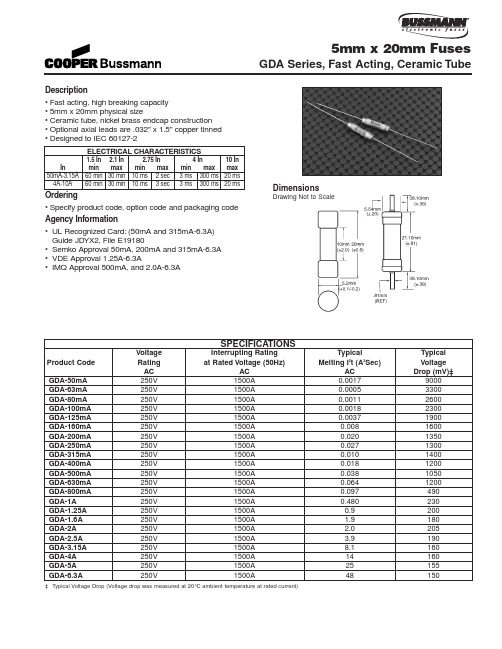
Dimensions
Drawing Not to Scale
Product Code
GDA-50mA GDA-63mA GDA-80mA GDA-100mA GDA-125mA GDA-160mA GDA-200mA GDA-250mA GDA-315mA GDA-400mA GDA-500mA GDA-630mA GDA-800mA GDA-1A GDA-1.25A GDA-1.6A GDA-2A GDA-2.5A GDA-3.15A GDA-4A GDA-5A GDA-6.3A
Description 100 pieces of fuses packed into a cardboard carton 1,000 pieces of fuses packed into a poly bag 1,500 pieces of fuses packed into tape on a reel
AC 1500A 1500A 1500A 1500A 1500A 1500A 1500A 1500A 1500A 1500A 1500A 1500A 1500A 1500A 1500A 1500A 1500A 1500A 1500A 1500A 1500A 1500A
‡ Typical Voltage Drop (Voltage drop was measured at 20°C ambient temperature at rated current)
Typical Melting I2t (A2Sec)
最全钢芯铝绞线技术全参数表
最全钢芯铝绞线技术参数表1 标准技术参数 (2)1.1 JL/G1A-50/30-12/7 标准技术参数 (2)1.2 JL/G1A-70/40-12/7标准技术参数 (4)1.3 JL/G1A-95/55-12/7 标准技术参数 (6)1.4 JL/G1A-120/20-26/7标准技术参数 (8)1.5 JL/G1A-120/25-7/7标准技术参数 (10)1.6 JL/G1A-150/20-24/7标准技术参数 (12)1.7 JL/G1A-150/35-30/7标准技术参数 (14)1.8 JL/G1A-185/30-26/7标准技术参数 (16)1.9 JL/G1A-185/45-30/7标准技术参数 (18)1.10 JL/G1A-240/30-24/7标准技术参数 (21)1.11 JL/G1A-240/40-26/7标准技术参数 (23)1.12 JL/G1A-300/25-48/7标准技术参数 (25)1.13 JL/G1A-300/40-24/7标准技术参数 (27)1.14 JL/G1A-300/50-26/7标准技术参数 (29)1.15 JL/G1A-400/35-48/7标准技术参数 (31)1.16 JL/G1A-400/50-54/7标准技术参数 (33)1.17 JL/G1A-400/65-26/7标准技术参数 (35)1.18 JL/G1A-500/45-48/7标准技术参数 (37)1.19 JL/G1A-500/65-54/7标准技术参数 (40)1.20 JL/G1A-630/45-45/7标准技术参数 (42)1.21 JL/G1A-630/55-48/7标准技术参数 (44)1.22 JL/G2A-720/50-45/7标准技术参数 (46)1.23 JL/G2A-720/90-54/19标准技术参数 (48)1.24 JL/G1A-800/55-45/7标准技术参数 (50)1.25 JL/G3A-900/40-72/7标准技术参数 (52)1.26 JL/G2A-900/75-84/7 标准技术参数 (55)1.27 JL/G3A-1000/45-72/7标准技术参数 (57)2 项目需求部分 (59)2.1 货物需求及供货范围一览表 (59)2.2 图纸资料提交单位 (60)2.3 工程概况 (60)2.4 使用条件 (60)2.5 项目单位技术差异 (61)3 投标人响应部分 (61)1 标准技术参数投标人应仔细阅读货物需求及供货范围一览表,并认真逐项填写所招标规格的钢芯铝绞线技术参数响应表中“投标人保证值”,不能以“响应”两字代替,不允许改动标准参数值。
螺杆真空泵真空泵说明书
(2)镀膜
(7)研究与开发
(12)化工制药
(3)冶金
(8)灯和电子管制造 (13)包装技术
(4)干燥工艺
(9)气槽工业
(14)检漏
(5)负载锁室
(10)空间模拟
(15)太阳能
(6)脱气
(11)电机工程
1.4型号及意义 LG150
LG——螺杆真空泵(为汉语拼音螺“Luo”和杆“Gan”的第一个大写字母)
警告:操作或修理本泵前,没有阅读使用说明书和采取 适当安全防范,可能会引起严重的伤害。
1 概述
1.1 概要
LG系列螺杆真空泵是一种干式运行,无接触,等螺距的螺杆型真空泵。它的
工作原理,是利用两个相平行的等螺距螺杆,在泵腔中作同步高速反向旋转而产
生吸气和排气作用。两螺杆经过精细动平衡处理,由轴承支撑,安装在泵壳中,
从泵的内表面上清理下来。当抽有腐蚀性的或有毒的气体,或像树脂一样有粘性
的材料时,本操作就显得尤其重要。
泵蒸汽冲洗:
当泵每次工艺过程结束后,关闭进气口主阀,无负载运行真空泵10-20分钟(干
运行,清洗净化)。本操作是消除或清洗在抽气过程中积聚在泵腔内的工艺气体
或可凝性蒸汽。这些残留在泵腔内的工艺材料是导致泵重新起动时发生过载的罪
本型泵采用了等螺距的螺杆型线,在螺杆的末端有内部压缩设计,即绝大部 分的压缩工作时在气体与排气口相通的时候完成的,也就是泵排出的最后阶段。 图3显示的是螺杆泵的P-V图表:(a)无内压缩;(b)最后阶段有压缩。PV图表 中显示的几个面积与泵吸取的能量成正比的。很明显地,采取适当的内压缩,有 利于降低功率的消耗,同时也减少了发热量。
(3)工作腔干式运行,适合抽除含有粉尘的气体和可凝性的气体。
钢芯铝绞线型号及规格表_概述解释说明

钢芯铝绞线型号及规格表概述解释说明1. 引言1.1 概述本篇文章旨在介绍钢芯铝绞线(ACSR)的型号及规格表,旨在为读者提供相关知识和理解。
钢芯铝绞线是一种电力传输和分配领域常用的导线材料,具有独特的性能和特点。
通过对各种型号和规格进行概括、解释与说明,读者将能够更好地了解该材料的应用及其在不同场景下的优势利用。
1.2 文章结构本文主要分为五个部分,以下是每个部分的内容:第一部分:引言- 第1.1节: 概述——简要介绍文章目标和内容。
- 第1.2节: 文章结构——详述本文组成部分以及各个部分的主题。
- 第1.3节: 目的——阐明介绍该文章内容的意图和目标。
第二部分:钢芯铝绞线(ACSR)简介- 第2.1节: 定义和特点——阐述钢芯铝绞线这种导线材料的定义、基本特点以及其所具备的优势。
- 第2.2节: 工作原理——介绍钢芯铝绞线在电力传输与分配中的工作原理,包括导电性能和耐久性等方面的分析。
- 第2.3节: 应用领域——探讨钢芯铝绞线在不同领域中的应用范围及实际运用情况。
第三部分:钢芯铝绞线型号及规格表解析- 第3.1节: 型号分类和命名规则——详述钢芯铝绞线各种型号的分类规则以及命名方式的含义。
- 第3.2节: 规格表解释说明——对钢芯铝绞线常用规格表中各项数据进行解读和说明。
- 第3.3节: 常用型号及其特性介绍——介绍几种常见型号的钢芯铝绞线,并说明其特性及适用场景。
第四部分:钢芯铝绞线的优势和不足- 第4.1节: 优势分析——列举并详述钢芯铝绞线相比其他导线材料所具备的优势,并分析其原因及作用。
- 第4.2节: 不足之处及改进措施——分析目前钢芯铝绞线存在的问题和不足,并提出一些改进策略或措施。
第五部分:结论- 第5.1节: 总结要点——总结文章中的重点和核心内容。
- 第5.2节: 发展前景展望——对钢芯铝绞线的发展前景进行展望与预测,指出可能的趋势和发展方向。
- 第5.3节: 研究建议和推荐使用场景——提供一些建议用于相关研究,并针对不同场景给出推荐的使用建议。
钢芯铝绞线技术响应表
实用标准文案精彩文档国家电网公司集中规模招标采购钢芯铝绞线招标文件(技术规范专用部分)2011 年 05实用标准文案1 标准技术参数 (1)1.1 JL/G1A-50/30-12/7 标准技术参数 (1)1.2 JL/G1A-70/40-12/7标准技术参数 (3)1.3 JL/G1A-95/55-12/7 标准技术参数 (6)1.4 JL/G1A-120/20-26/7标准技术参数 (8)1.5 JL/G1A-120/25-7/7标准技术参数 (10)1.6 JL/G1A-150/20-24/7标准技术参数 (13)1.7 JL/G1A-150/35-30/7标准技术参数 (15)1.8 JL/G1A-185/30-26/7标准技术参数 (17)1.9 JL/G1A-185/45-30/7标准技术参数 (20)1.10 JL/G1A-240/30-24/7标准技术参数 (23)1.11 JL/G1A-240/40-26/7标准技术参数 (25)1.12 JL/G1A-300/25-48/7标准技术参数 (27)1.13 JL/G1A-300/40-24/7标准技术参数 (30)1.14 JL/G1A-300/50-26/7标准技术参数 (32)1.15 JL/G1A-400/35-48/7标准技术参数 (35)1.16 JL/G1A-400/50-54/7标准技术参数 (37)1.17 JL/G1A-400/65-26/7标准技术参数 (40)1.18 JL/G1A-500/45-48/7标准技术参数 (42)1.19 JL/G1A-500/65-54/7标准技术参数 (45)1.20 JL/G1A-630/45-45/7标准技术参数 (47)1.21 JL/G1A-630/55-48/7标准技术参数 (50)1.22 JL/G2A-720/50-45/7标准技术参数 (52)1.23 JL/G2A-720/90-54/19标准技术参数 (54)1.24 JL/G1A-800/55-45/7标准技术参数 (57)1.25 JL/G3A-900/40-72/7标准技术参数 (59)1.26 JL/G2A-900/75-84/7 标准技术参数 (61)1.27 JL/G3A-1000/45-72/7标准技术参数 (63)2 项目需求部分 (66)2.1货物需求及供货范围一览表 (66)2.2图纸资料提交单位 (66)2.3工程概况 (66)2.4使用条件 (67)2.5项目单位技术差异 (67)3 投标人响应部分 (67)精彩文档实用标准文案1 标准技术参数投标人应仔细阅读货物需求及供货范围一览表,并认真逐项填写所招标规格的钢芯铝绞线技术参数响应表中“投标人保证值”,不能以“响应”两字代替,不允许改动标准参数值。
基于高压输电线路节能导线选型的研究
基于高压输电线路节能导线选型的研究发布时间:2022-09-14T06:28:28.370Z 来源:《中国电业与能源》2022年5月9期作者:陈启正[导读] 随着国家节能减排产业政策的推行,中国南方电网有限责任公司在电力基本建设过程中采用新技术、新材料、新工艺建设资源节约型、环境友好型的绿色输电线路日益受到重视。
陈启正深圳供电规划设计院有限公司广东,深圳518000摘要:随着国家节能减排产业政策的推行,中国南方电网有限责任公司在电力基本建设过程中采用新技术、新材料、新工艺建设资源节约型、环境友好型的绿色输电线路日益受到重视。
推行全寿命周期管理,将全寿命周期管理理念与方法应用到绿色输电线路设计和建设中是实现电网科学发展、和谐发展之路。
关键词:节能导线、绿色输电线路1节能导线的定义及类型1.1节能导线的定义与广泛采用的铝线导电率为61%IACS的钢芯铝绞线相比,在等外径(等总截面)条件下,直流电阻(20℃)更小的导线称之为节能导线。
1.2节能导线的类型近年来,国内陆续研制出多种新型节能导线和增容导线,其中增容导线虽然可以提高输送容量,但其电阻损耗非常大,使用起来非常不经济,故目前国内比较常见和最具有代表性的主要有钢芯高导电率硬铝绞线、铝合金芯铝绞线和中强度全铝合金绞线三种节能导线,该三种节能导线与常规钢芯铝绞线相比,铝(铝合金)导体材料性能不同,导电率有所差异,下面分别介绍其特点。
1.2.1钢芯高导电率硬铝绞线高导电率电工硬铝以多根镀锌钢线为芯,外部同心绞合多层导电率在61.5%IACS至63%IACS之间的硬铝线构成,与铝截面相同的普通钢芯铝绞线相比,铝线导电率的提高,可使导线整体直流电阻值降低,电能损耗减少。
1.2.2铝合金芯铝绞线铝合金(铝镁硅合金)的基体为电工硬铝,以多根导电率为52.5%IACS或53%IACS之间的硬铝线构成。
在等总截面的应用条件下,由于铝合金芯替代了基本无导电能力的钢芯,其直流电阻小于普通钢芯铝绞线,提高了导电能力。
