LMV358ID
lm358原理
lm358原理
LM358是一款双路运算放大器,用于模拟信号处理。
它由两
个独立的运算放大器组成,每个放大器都有一个差动输入和单端输出。
LM358主要用于放大和处理小信号,如传感器输出、音频信号、滤波器等。
LM358采用双电源供电(正电源和负电源),典型工作电压
范围为3V至32V。
它的工作电流较低,通常在1至2毫安培
之间。
这使得LM358非常适用于低功耗应用场合。
LM358的差动输入具有高输入电阻,通常为1M欧姆。
这样
的高输入电阻使得它对输入信号的干扰较小,同时也方便与其他电路连接。
在LM358中,差动输入之间的电压差会被放大,然后送入输
出级。
输出级由NPN和PNP晶体管组成。
输出级的工作电流
由外部电路决定,输出电压则取决于差动输入电压和输出级的放大倍数。
在使用LM358时,一般需要外部电压稳定器和耦合电容等辅
助电路。
这些辅助电路可以提供稳定的工作条件,以获得精确的放大效果。
需要注意的是,作为一款模拟电路元件,LM358不能直接处
理数字信号。
如果需要处理数字信号,可以将其与数字电路相结合,例如使用运算放大器作为比较器或滤波器的一部分。
总结起来,LM358是一款双路运算放大器,主要用于放大和处理模拟信号。
它具有低工作电流、高输入电阻等特点。
在使用时需要搭配辅助电路,并注意与数字电路的结合使用。
lm358应用电路讲解

lm358应用电路讲解
“lm358应用电路讲解”指的是对LM358运算放大器的应用电路进行详细讲解和分析。
LM358是一种双运算放大器,具有高直流电压增益、低输入偏置电流、低输入失调电压和失调电流等特点,适用于多种应用场景,如传感器放大器、直流增益模块、音频放大器、工业控制等。
对于LM358的应用电路讲解,一般会涉及以下方面:
1.电源电压与电源电流:LM358需要一个适当的电源供电,其电源电压范围
很宽,单电源供电范围为3-30V,双电源供电范围为±1.5-±15V。
同时,它的电源电流与电源电压基本无关。
2.输入信号:LM358的输入信号可以是差分信号或单端信号,输入阻抗很高,
可以忽略输入电阻对信号的影响。
在选择输入信号时,需要考虑放大倍数、频率响应等参数。
3.输出信号:LM358的输出信号可以用来驱动电阻性或电感性负载,其输出
阻抗较小,负载效应较小。
输出信号的范围可以根据需要进行调整。
4.连接方式:LM358可以通过不同的方式连接以实现不同的功能,如差分输
入/输出、单端输入/输出等。
在选择连接方式时,需要考虑电路的拓扑结构、噪声和干扰等因素。
5.线性与非线性应用:LM358在许多领域中都有应用,如音频放大、传感器
信号处理等。
在非线性应用中,如比较器、触发器等,需要注意输入信号的幅度和频率对输出结果的影响。
总的来说,“lm358应用电路讲解”主要涵盖了LM358运算放大器的电源配置、输入输出信号处理、连接方式选择以及在各种领域中的应用等方面。
通过深入理解这些内容,可以更好地掌握LM358的应用技巧,设计出性能优良的电路系统。
常用低电压型运算放大器一览

85 86 57 57 57 57
8 No 8 No 39 Yes 39 Yes 39 Yes 39 Yes
Out Out In/Out In/Out In/Out In/Out
5SOT23/40~85 PDIP-8/40~85 SOIC-8/40~125 SOIC-8/40~125 PDIP-8/40~125
39 Yes
Out
5
250000
50
39 Yes
Out
5
250000
50
39 Yes
Out
5
250000
50
39 Yes
Out
5
250000
50
39 Yes
Out
5
250000
50
39 Yes
Out
5
250000
50
39 Yes
Out
3 5
10 10
74 76
32 Yes 5 Yes
In/Out In/Out
12
150
80
5
OPA300AI DBVT OPA349NA /250
1 Yes
5.5
2.7
12
150
80
5
1 Yes
5.5
1.8
0
0.07
0.02
10
OPA349UA OPA350PA OPA354AI DBVT OPA355UA OPA356AI DBVT OPA357AI DBVT OPA360AI DCKT OPA363AI D OPA363AI DBVT OPA4364A IPWT
单路低功耗, 低偏置电 流,300mA 驱动 USD 0.80 单路低功耗, 低偏置电 流,300mA 驱动 USD 0.80 高输出驱动, 低电压,运放 USD 0.75 USD 0.90
LKX358中文资料规格书

电气特性: 5.0 V
除非另有说明,否则 Ta=25°C,RL=10kΩ连接至 Vs/2,Vcm=Vout=Vs/2。
LK1358/LK2358/LK4358
参数
条件
最小 典型 最大 单位
输入特性
输入失调电压 输入失调温度漂移 输入偏置电流 输入失调电流 输入共模电压范围 共模抑制比
开环增益
输出特性
版本号:1.1
2020 年 06 月 5
兰科半导体
1.2MHz, 30μA, 轨对轨输入/输出 CMOS 运算放大器
特性曲线
除非另有说明,否则 Ta=25°C,Vs=5V,RL=10kΩ连接到 Vs/2,Vcm=Vout=Vs/2。
地址:深圳市福田区益田路皇都广场 A 座 2305 室
版本号:1.1
3
28 22 21
MHz V/μs μs μs
nV/Hz nV/Hz fA/√Hz
电气特性: 2.7 V
除非另有说明,否则 Ta=25°C,RL=10kΩ连接至 Vs/2,Vcm=Vout=Vs/2。
LK1358/LK2358/LK4358
参数
条件
最小 典型 最大 单位
输入特性
输入失调电压
VOS
1
4
66
79
AOL RL = 2kΩ, VOUT = 0.3V to 4.7V
72
85
RL = 100kΩ, VOUT = 0.05V to 4.95V
80
88
4
mV
μV/°C
pA
pA
5.1
V
dB
dB dB
输出电压降幅
输出电流 电源
RL = 2kΩ RL = 100kΩ IOUT RL = 10Ω to VS/2
lm358中文资料汇总(lm358引脚图及功能

lm358中文资料汇总(lm358引脚图及功能lm358概述LM358是双运算放大器。
内部包括有两个独立的、高增益、内部频率补偿的运算放大器,适合于电源电压范围很宽的单电源使用,也适用于双电源工作模式,在推荐的工作条件下,电源电流与电源电压无关。
它的使用范围包括传感放大器、直流增益模块和其他所有可用单电源供电的使用运算放大器的场合。
lm358特性内部频率补偿直流电压增益高(约100dB)单位增益频带宽(约1MHz)电源电压范围宽:单电源(3—30V)双电源(±1.5 一±15V)压摆率(0.3V/us)低功耗电流,适合于电池供电· 低输入偏流低输入失调电压和失调电流共模输入电压范围宽,包括接地差模输入电压范围宽,等于电源电压范围输出电压摆幅大(0 至Vcc-1.5V)lm358内部原理图lm358引脚图及功能LM358 的封装形式有塑封 8 引线双列直插式和贴片式。
LM358引脚功能:1脚是输出端,2脚是反相输入端,3脚是同相输入端;4脚是负电源(双电源工作时)或地(单电源工作时);5脚是同相输入端;6脚是反相输入端;7脚是输出端;8脚是正电源;1、2、3脚是一个运放通道,5、6、7脚为另一运放通道。
lm358工作原理工作原理:8脚主供电输入,2脚电压与3脚电压比较,6脚电压与5脚电压比较,分别对应两个独立的输出:1OUT与2OUT 当1IN+大于1IN- 2IN+大于2IN-时,1OUT 2OUT输出高电平当1IN+小于1IN- 2IN+小于2IN-时,1OUT 2OUT输出低电平LM358输出端不需要上拉电阻,输出电压范围为:0V~VCC-1.5V,这点与LM393是不同的LM358封装尺寸及外形图lm358参数输入偏置电流45 nA输入失调电流50 nA输入失调电压2.9mV输入共模电压最大值VCC~1.5 V共模抑制比80d电源抑制比100dBlm358应用电路图一:红外线探测报警器该报警器能探测人体发出的红外线,当人进入报警器的监视区域内,即可发出报警声,适用于家庭、办公室、仓库、实验室等比较重要场合防盗报警。
最新LM358功能 中文资料

LM358功能中文资料LM358是常用的双运放,这里我们介绍一下他的一些资料以及简单电路应用等.简介:LM358里面包括有两个高增益、独立的、内部频率补偿的双运放,适用于电压范围很宽的单电源,而且也适用于双电源工作方式,它的应用范围包括传感放大器、直流增益模块和其他所有可用单电源供电的使用运放的地方使用。
〈LM358引脚图及引脚功能〉LM358封装有塑封8引线双列直插式和贴片式两种。
LM358的特点:. 内部频率补偿. 低输入偏流. 低输入失调电压和失调电流. 共模输入电压范围宽,包括接地. 差模输入电压范围宽,等于电源电压范围. 直流电压增益高(约100dB). 单位增益频带宽(约1MHz). 电源电压范围宽:单电源(3—30V);. 双电源(±1.5 一±15V). 低功耗电流,适合于电池供电. 输出电压摆幅大(0 至Vcc-1.5V)LM358稳压电路制作电路原理:本稳压器的核心器件采用LM358。
电路原理如下图所示。
它主要由供电、基准电压、电压取样比较等组成。
市电从变压器的1、2头输入,3、4头为自耦调压抽头,5、6头为控制电路的电源及取样抽头。
市电电压正常时,因C点电压始终为3V(即R1降压DW稳压所得),A、B点均大于3V,故A1、A2(lm358芯片)输出低电平;当市电电压下降时,5、6头的电压也随之下降,A点电压也跟着下降,当A点电压下降到低于3V时,A1输出高电平,使三极管V1饱和导通,继电器K1吸合,将调压器输出调于1、3头;当市电电压继续下降时,同理B点电压低于3V时,(VA 反之,如果电压升高时,B点电压也随之升高,当B点电压高于3V时,A2输出低电平,V2截止,H2释放,输出端调至1、3头;当市电电压继续升高时,A点电压高于3V,A1输出低电平,V1截止,K1释放,输出端调至1、2头。
A1、A2为运放,在这里作电压比较器用;IC1为三端稳压块,它为运放及继电器提供供电电源;VD5、VD6为保护二极管。
lm358集成运算放大电路内部电路

LM358集成运算放大电路内部电路一、LM358集成运算放大电路的概述LM358是一款双运放集成电路,广泛应用于模拟电路中。
它包含两个独立的运算放大器,能够在单电源供电的情况下工作。
LM358具有低功耗、较高的共模抑制比以及较高的带宽等特点,因此在各种电子设备中得到了广泛的应用。
二、LM358集成运算放大电路的内部结构LM358的内部结构主要包括输入级、差动放大器级、输出级以及复位电路等部分。
以下是LM358内部电路的详细分析:1. 输入级LM358的输入级采用差分放大器结构。
它由输入级晶体管、偏置电阻、调零电阻和调整偏置电源等组成。
输入级的主要作用是将输入信号进行放大,并提供给差动放大器级进一步处理。
2. 差动放大器级差动放大器级是LM358内部的核心部分,它主要由两个输入级晶体管、两个晶体管负载、差动放大器晶体管以及输出电阻等组成。
差动放大器级的主要作用是对输入信号进行放大和处理,产生差动信号,并通过负反馈作用于输出级。
3. 输出级LM358的输出级主要由输出级晶体管、输出电阻和复位电路等组成。
输出级的主要作用是接收差动信号并进行进一步放大,最终输出给外部负载。
4. 复位电路LM358内部还包含复位电路,主要用于对运算放大器的输出进行复位,以确保运算放大器在启动和关闭时的稳定性。
三、LM358集成运算放大电路的工作原理LM358集成运算放大电路的工作原理可以概括为:通过输入级将输入信号进行放大,经过差动放大器级产生差动信号,然后经过输出级进行进一步放大,并最终输出给外部负载。
在整个工作过程中,LM358通过负反馈控制输出,使得输出电压与输入电压间保持特定的关系,从而实现运算放大器的放大功能。
四、LM358集成运算放大电路的应用LM358集成运算放大电路广泛应用于各种模拟电路中,常见的应用包括信号放大、滤波、比较、矩阵运算、PID控制等。
由于LM358具有双运放结构,因此还可以应用于一些需要两路运算放大器的电路设计中。
LMV358IDE4中文资料
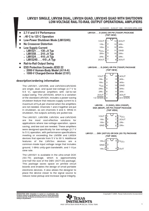
PACKAGING INFORMATIONOrderableDevice Status (1)Package Type Package Drawing Pins Package Qty Eco Plan (2)Lead/Ball Finish MSL Peak Temp (3)LMV321IDBVR ACTIVE SOT-23DBV 53000Green (RoHS &no Sb/Br)CU NIPDAU Level-1-260C-UNLIM LMV321IDBVT ACTIVE SOT-23DBV 5250Green (RoHS &no Sb/Br)CU NIPDAU Level-1-260C-UNLIM LMV321IDBVTE4ACTIVE SOT-23DBV 5250Green (RoHS &no Sb/Br)CU NIPDAU Level-1-260C-UNLIM LMV321IDCKR ACTIVE SC70DCK 53000Green (RoHS &no Sb/Br)CU NIPDAU Level-1-260C-UNLIM LMV321IDCKRG4ACTIVE SC70DCK 53000Green (RoHS &no Sb/Br)CU NIPDAU Level-1-260C-UNLIM LMV321IDCKT ACTIVE SC70DCK 5250Green (RoHS &no Sb/Br)CU NIPDAU Level-1-260C-UNLIM LMV321IDCKTE4ACTIVE SC70DCK 5250Green (RoHS &no Sb/Br)CU NIPDAU Level-1-260C-UNLIM LMV324ID ACTIVE SOIC D 1450Green (RoHS &no Sb/Br)CU NIPDAU Level-1-260C-UNLIM LMV324IDR ACTIVE SOIC D 142500Green (RoHS &no Sb/Br)CU NIPDAU Level-1-260C-UNLIM LMV324IPWR ACTIVE TSSOP PW 142000Green (RoHS &no Sb/Br)CU NIPDAU Level-1-260C-UNLIM LMV324IPWRG4ACTIVE TSSOP PW 142000Green (RoHS &no Sb/Br)CU NIPDAU Level-1-260C-UNLIM LMV324QD ACTIVE SOIC D 1450Green (RoHS &no Sb/Br)CU NIPDAU Level-1-260C-UNLIM LMV324QDR ACTIVE SOIC D 142500Green (RoHS &no Sb/Br)CU NIPDAU Level-1-260C-UNLIM LMV324QPW ACTIVE TSSOP PW 1490Green (RoHS &no Sb/Br)CU NIPDAU Level-1-260C-UNLIM LMV324QPWE4ACTIVE TSSOP PW 1490Green (RoHS &no Sb/Br)CU NIPDAU Level-1-260C-UNLIM LMV324QPWR ACTIVE TSSOP PW 142000Green (RoHS &no Sb/Br)CU NIPDAU Level-1-260C-UNLIM LMV324SID ACTIVE SOIC D 1640Green (RoHS &no Sb/Br)CU NIPDAU Level-1-260C-UNLIM LMV324SIDE4ACTIVE SOIC D 1640Green (RoHS &no Sb/Br)CU NIPDAU Level-1-260C-UNLIM LMV324SIDR ACTIVE SOIC D 162500Green (RoHS &no Sb/Br)CU NIPDAU Level-1-260C-UNLIM LMV324SIDRE4ACTIVE SOIC D 162500Green (RoHS &no Sb/Br)CU NIPDAU Level-1-260C-UNLIM LMV324SIPWR ACTIVE TSSOP PW 162000Green (RoHS &no Sb/Br)CU NIPDAU Level-1-260C-UNLIM LMV324SIPWRE4ACTIVE TSSOP PW 162000Green (RoHS &no Sb/Br)CU NIPDAU Level-1-260C-UNLIM LMV358ID ACTIVE SOIC D 875Green (RoHS &no Sb/Br)CU NIPDAU Level-1-260C-UNLIM LMV358IDDUR ACTIVE VSSOP DDU 83000Green (RoHS &no Sb/Br)CU NIPDAU Level-1-260C-UNLIM LMV358IDDURE4ACTIVEVSSOPDDU83000Green (RoHS &no Sb/Br)CU NIPDAULevel-1-260C-UNLIM6-Dec-2006Orderable Device Status(1)PackageType PackageDrawing Pins PackageQtyEco Plan(2)Lead/Ball Finish MSL Peak Temp(3)LMV358IDE4ACTIVE SOIC D875Green(RoHS&no Sb/Br)CU NIPDAU Level-1-260C-UNLIMLMV358IDG4ACTIVE SOIC D875Green(RoHS&no Sb/Br)CU NIPDAU Level-1-260C-UNLIMLMV358IDGKR ACTIVE MSOP DGK82500Green(RoHS&no Sb/Br)CU NIPDAU Level-1-260C-UNLIMLMV358IDGKRG4ACTIVE MSOP DGK82500Green(RoHS&no Sb/Br)CU NIPDAU Level-1-260C-UNLIMLMV358IDR ACTIVE SOIC D82500Green(RoHS&no Sb/Br)CU NIPDAU Level-1-260C-UNLIMLMV358IDRE4ACTIVE SOIC D82500Green(RoHS&no Sb/Br)CU NIPDAU Level-1-260C-UNLIMLMV358IDRG4ACTIVE SOIC D82500Green(RoHS&no Sb/Br)CU NIPDAU Level-1-260C-UNLIMLMV358IPW ACTIVE TSSOP PW8150Green(RoHS&no Sb/Br)CU NIPDAU Level-1-260C-UNLIMLMV358IPWE4ACTIVE TSSOP PW8150Green(RoHS&no Sb/Br)CU NIPDAU Level-1-260C-UNLIMLMV358IPWG4ACTIVE TSSOP PW8150Green(RoHS&no Sb/Br)CU NIPDAU Level-1-260C-UNLIMLMV358IPWR ACTIVE TSSOP PW82000Green(RoHS&no Sb/Br)CU NIPDAU Level-1-260C-UNLIMLMV358IPWRE4ACTIVE TSSOP PW82000Green(RoHS&no Sb/Br)CU NIPDAU Level-1-260C-UNLIMLMV358IPWRG4ACTIVE TSSOP PW82000Green(RoHS&no Sb/Br)CU NIPDAU Level-1-260C-UNLIMLMV358QD ACTIVE SOIC D875Green(RoHS&no Sb/Br)CU NIPDAU Level-1-260C-UNLIMLMV358QDDUR ACTIVE VSSOP DDU83000Green(RoHS&no Sb/Br)CU NIPDAU Level-1-260C-UNLIMLMV358QDDURE4ACTIVE VSSOP DDU83000Green(RoHS&no Sb/Br)CU NIPDAU Level-1-260C-UNLIMLMV358QDE4ACTIVE SOIC D875Green(RoHS&no Sb/Br)CU NIPDAU Level-1-260C-UNLIMLMV358QDGKR ACTIVE MSOP DGK82500Green(RoHS&no Sb/Br)CU NIPDAU Level-1-260C-UNLIMLMV358QDGKRG4ACTIVE MSOP DGK82500Green(RoHS&no Sb/Br)CU NIPDAU Level-1-260C-UNLIMLMV358QDR ACTIVE SOIC D82500Green(RoHS&no Sb/Br)CU NIPDAU Level-1-260C-UNLIMLMV358QDRE4ACTIVE SOIC D82500Green(RoHS&no Sb/Br)CU NIPDAU Level-1-260C-UNLIMLMV358QPW ACTIVE TSSOP PW8150Green(RoHS&no Sb/Br)CU NIPDAU Level-1-260C-UNLIMLMV358QPWE4ACTIVE TSSOP PW8150Green(RoHS&no Sb/Br)CU NIPDAU Level-1-260C-UNLIMLMV358QPWR ACTIVE TSSOP PW82000Green(RoHS&no Sb/Br)CU NIPDAU Level-1-260C-UNLIMLMV358QPWRE4ACTIVE TSSOP PW82000Green(RoHS&no Sb/Br)CU NIPDAU Level-1-260C-UNLIM (1)The marketing status values are defined as follows:6-Dec-2006ACTIVE:Product device recommended for new designs.LIFEBUY:TI has announced that the device will be discontinued,and a lifetime-buy period is in effect.NRND:Not recommended for new designs.Device is in production to support existing customers,but TI does not recommend using this part in a new design.PREVIEW:Device has been announced but is not in production.Samples may or may not be available.OBSOLETE:TI has discontinued the production of the device.(2)Eco Plan -The planned eco-friendly classification:Pb-Free (RoHS),Pb-Free (RoHS Exempt),or Green (RoHS &no Sb/Br)-please check /productcontent for the latest availability information and additional product content details.TBD:The Pb-Free/Green conversion plan has not been defined.Pb-Free (RoHS):TI's terms "Lead-Free"or "Pb-Free"mean semiconductor products that are compatible with the current RoHS requirements for all 6substances,including the requirement that lead not exceed 0.1%by weight in homogeneous materials.Where designed to be soldered at high temperatures,TI Pb-Free products are suitable for use in specified lead-free processes.Pb-Free (RoHS Exempt):This component has a RoHS exemption for either 1)lead-based flip-chip solder bumps used between the die and package,or 2)lead-based die adhesive used between the die and leadframe.The component is otherwise considered Pb-Free (RoHS compatible)as defined above.Green (RoHS &no Sb/Br):TI defines "Green"to mean Pb-Free (RoHS compatible),and free of Bromine (Br)and Antimony (Sb)based flame retardants (Br or Sb do not exceed 0.1%by weight in homogeneous material)(3)MSL,Peak Temp.--The Moisture Sensitivity Level rating according to the JEDEC industry standard classifications,and peak solder temperature.Important Information and Disclaimer:The information provided on this page represents TI's knowledge and belief as of the date that it is provided.TI bases its knowledge and belief on information provided by third parties,and makes no representation or warranty as to the accuracy of such information.Efforts are underway to better integrate information from third parties.TI has taken and continues to take reasonable steps to provide representative and accurate information but may not have conducted destructive testing or chemical analysis on incoming materials and chemicals.TI and TI suppliers consider certain information to be proprietary,and thus CAS numbers and other limited information may not be available for release.In no event shall TI's liability arising out of such information exceed the total purchase price of the TI part(s)at issue in this document sold by TI to Customer on an annualbasis.6-Dec-2006IMPORTANT NOTICETexas Instruments Incorporated and its subsidiaries (TI) reserve the right to make corrections, modifications, enhancements, improvements, and other changes to its products and services at any time and todiscontinue any product or service without notice. Customers should obtain the latest relevant informationbefore placing orders and should verify that such information is current and complete. All products are soldsubject to TI’s terms and conditions of sale supplied at the time of order acknowledgment.TI warrants performance of its hardware products to the specifications applicable at the time of sale inaccordance with TI’s standard warranty. Testing and other quality control techniques are used to the extentTI deems necessary to support this warranty. Except where mandated by government requirements, testingof all parameters of each product is not necessarily performed.TI assumes no liability for applications assistance or customer product design. Customers are responsiblefor their products and applications using TI components. To minimize the risks associated with customerproducts and applications, customers should provide adequate design and operating safeguards.TI does not warrant or represent that any license, either express or implied, is granted under any TI patentright, copyright, mask work right, or other TI intellectual property right relating to any combination, machine,or process in which TI products or services are used. Information published by TI regarding third-partyproducts or services does not constitute a license from TI to use such products or services or a warranty orendorsement thereof. Use of such information may require a license from a third party under the patents orother intellectual property of the third party, or a license from TI under the patents or other intellectualproperty of TI.Reproduction of information in TI data books or data sheets is permissible only if reproduction is withoutalteration and is accompanied by all associated warranties, conditions, limitations, and notices.Reproduction of this information with alteration is an unfair and deceptive business practice. TI is notresponsible or liable for such altered documentation.Resale of TI products or services with statements different from or beyond the parameters stated by TI forthat product or service voids all express and any implied warranties for the associated TI product or serviceand is an unfair and deceptive business practice. TI is not responsible or liable for any such statements.Following are URLs where you can obtain information on other Texas Instruments products and applicationsolutions:Products ApplicationsAmplifiers Audio /audioData Converters Automotive /automotive/broadbandBroadbandDSP DigitalControl /digitalcontrol Interface Military /military Logic Power Mgmt Optical Networking /opticalnetworkSecurity /security Microcontrollers Low Power Wireless /lpw Telephony /telephonyVideo & Imaging /video/wirelessWirelessMailing Address: Texas InstrumentsPost Office Box 655303 Dallas, Texas 75265Copyright © 2007, Texas Instruments Incorporated。
lmv358

(2)集成运放电磁放大检波电路
三级管电磁放大检波电路简单实用,已经在比赛中得到了广泛的使用。
如果需要进一步提高检波的灵敏度,可以再增加一级三极管放大电路。
使用三极管组成的分立元件的放大检波电路存在着一些缺点:
(1)工作点电压调整比较复杂;
(2)电路的放大倍数依赖于三极管的电流放大倍数和基极导通阻抗等,比较分散;
(3)由于检波二极管的正向导通电压的存在对于非常弱的电磁信号无法进行检波。
采用集成放大电路可以简化电路设计,提高电路的性能。
下面给出了一种基于输出满电压量程(Rail-to-Rail,轨对轨)运算放大器的电磁放大检波电路。
R-R运放一般工作在单电源供电状态下,输出电压范围基本接近于电源电压和地。
输入的共模电压范围宽。
常用到的R-R运放包括LMV321,LMV358,LMV324,AX4451等。
请注意前面三种运放名称都是LMV,这些运放都有前缀为LM相对应型号的运放。
LMV运放与LM运放封装管脚相同,只是LMV为输出满电压量程输出满电压量程。
表格3-1给出了LMV358的主要电气性能,它的共模输入电压范围可以低于0V。
LM358工作原理

LM358工作原理LM358是一种双运算放大器集成电路,它是一款低功耗、低噪声、高利得的放大器。
它由Fairchild Semiconductor公司推出,可以在广泛的应用中使用,例如放大、滤波、反相和非反相放大器、比较器以及信号调理。
LM358芯片内部包含两个独立的放大器,每个放大器有一个反相输入端(IN-)和一个非反相输入端(IN+)。
它们共享一个电源和地引脚。
在测量电路中,通常将其中一个放大器用于信号的放大,而另一个放大器用于信号的比较。
差动对由两个晶体管组成,每个晶体管有一个基极(B),一个发射极(E)和一个集电极(C)。
其中,一个晶体管的基极连接到IN+输入端,另一个晶体管的基极连接到IN-输入端。
两个发射极通过一个电阻连接到地,这样电流就会流过这两个发射极。
两个晶体管的集电极通过一个电阻连接到正电源,而共同集电极通过一个电阻连接到负电源。
这样,形成了一个基本的差动放大电路。
在输入信号被引入差动放大电路时,由于两个晶体管的差异,会出现一个差模电压。
晶体管的差模增益使得输入信号得以放大。
输出级是由一个输出放大器和一个电流源组成。
输出放大器由一个晶体管和一个负载电阻组成。
晶体管的基极连接到差动放大器的集电极,晶体管的集电极连接到正电源,晶体管的发射极连接到电流源。
负载电阻连接到晶体管的集电极和负电源之间。
当输入信号经过差动放大器放大以后,就会进入输出级。
输出级将差动放大电路的输出信号经过适当的增益处理,然后输出到负载电阻上。
在实际应用中,通过调整差动放大器和输出级的电阻值,可以实现不同的放大倍数和频率响应。
此外,LM358还具有过载保护电路,可以防止电流过载引起的损坏。
总之,LM358是一款功能强大、性能稳定的放大器集成电路。
它适用于各种应用场景,并且具有良好的抗噪声和放大特性。
通过合理设计电路,可以实现多种放大倍数和频率响应。
LM358工作原理分析
LM358工作原理分析LM358是一种常用的双运放集成电路,具有广泛的应用范围。
本文将对LM358的工作原理进行分析,以便更好地理解其工作机制。
一、LM358简介1.1 LM358是一种双运放集成电路,内部含有两个独立的运放。
1.2 LM358的工作电压范围为3V至32V,工作温度范围为-40°C至105°C。
1.3 LM358具有低功耗、高增益、高共模抑制比等特点,适合于各种电路设计。
二、LM358的内部结构2.1 LM358内部包含两个独立的运放,每一个运放有一个输入端、一个输出端和一个反馈端。
2.2 LM358的输入端通过差动放大器进行信号放大,输出端通过共模放大器进行信号输出。
2.3 LM358的反馈端通过反馈电阻与输入端相连,实现对信号的反馈控制。
三、LM358的工作原理3.1 LM358的工作原理基于运放的反馈控制机制,通过调节输入端的电压来控制输出端的电压。
3.2 当输入端的电压高于反馈电阻端的电压时,输出端将输出高电平;反之,输出端将输出低电平。
3.3 LM358的工作原理可以通过反馈电阻的调节来实现对信号的放大或者衰减,从而实现不同的电路功能。
四、LM358的应用领域4.1 LM358广泛应用于信号放大、滤波、比较、积分等电路设计中。
4.2 LM358可用于传感器信号放大、运算放大器、比较器等电路设计。
4.3 LM358还可用于电压尾随器、电压源、振荡器等电路设计,具有较高的灵便性和可靠性。
五、LM358的优缺点5.1 优点:LM358具有低功耗、高增益、高共模抑制比等特点,适合于各种电路设计。
5.2 缺点:LM358的带宽受限,不适合于高频信号处理;输入电压范围较窄,需要外部电源支持。
5.3 总体而言,LM358作为一种常用的双运放集成电路,在各种电路设计中具有重要的应用价值。
通过以上对LM358工作原理的分析,我们可以更好地理解其内部结构和工作机制,为电路设计和应用提供参考。
LM358工作原理分析
LM358工作原理分析LM358是一种常用的双运算放大器,常用于各种电路中,如放大器、滤波器、比较器等。
本文将详细分析LM358的工作原理,包括其内部电路结构、输入输出特性以及应用场景等。
一、LM358的内部电路结构LM358由两个独立的运算放大器组成,每一个运算放大器都有一个差分输入和一个单端输出。
它的内部电路结构包括一个差分输入级、一个电流镜像级、一个级联放大器和一个输出级。
1. 差分输入级:差分输入级由两个晶体管组成,一个是NPN型晶体管,另一个是PNP型晶体管。
这两个晶体管构成为了一个差分对,用于接收输入信号。
2. 电流镜像级:电流镜像级由两个晶体管组成,一个是NPN型晶体管,另一个是PNP型晶体管。
这两个晶体管构成为了一个电流镜像电路,用于提供稳定的偏置电流。
3. 级联放大器:级联放大器由多个晶体管组成,用于放大差分输入级的信号。
它通过级联连接的方式将输入信号放大到合适的幅度。
4. 输出级:输出级由一个晶体管和一个电流源组成,用于输出放大后的信号。
它将放大后的信号转换为电流输出,可以连接到负载电阻上,实现电压输出。
二、LM358的输入输出特性LM358的输入输出特性对于了解其工作原理非常重要。
1. 输入特性:- 差模输入电压范围:LM358的差模输入电压范围通常为±1V,即输入信号的幅值不能超过±1V,否则可能导致失真。
- 共模输入电压范围:LM358的共模输入电压范围通常为0V至Vcc-1.5V,其中Vcc为供电电压。
超过这个范围的共模输入电压可能导致失真。
- 输入偏置电流:LM358的输入偏置电流通常为50nA至500nA,即输入信号引入的偏置电流较小。
2. 输出特性:- 输出电压范围:LM358的输出电压范围通常为0V至Vcc-1.5V,其中Vcc为供电电压。
超过这个范围的输出电压可能导致失真。
- 输出电流:LM358的输出电流通常为20mA,即输出电流较大,可以驱动较大的负载电阻。
LM358技术参数

下载:lm358中文资料LM358是常用的双运放,这里我们介绍一下他的一些资料以及简单电路应用等,有什么问题请去电子论坛.简介:LM358里面包括有两个高增益、独立的、内部频率补偿的双运放,适用于电压范围很宽的单电源,而且也适用于双电源工作方式,它的应用范围包括传感放大器、直流增益模块和其他所有可用单电源供电的使用运放的地方使用。
〈lm358引脚图及引脚功能〉LM358封装有塑封8引线双列直插式和贴片式两种。
LM358的特点:.内部频率补偿.低输入偏流.低输入失调电压和失调电流.共模输入电压范围宽,包括接地.差模输入电压范围宽,等于电源电压范围.直流电压增益高(约100dB).单位增益频带宽(约1MHz).电源电压范围宽:单电源(3—30V);.双电源(±1.5一±15V).低功耗电流,适合于电池供电.输出电压摆幅大(0至Vcc-1.5V)图1DIP塑封引脚图引脚功能图2圆形金属壳封装管脚图图3内部电路原理图lm358中文资料LM358内部包括有两个独立的、高增益、内部频率补偿的双运算放大器,适合于电源电压范围很宽的单电源使用,也适用于双电源工作模式,在推荐的工作条件下,电源电流与电源电压无关。
它的使用范围包括传感放大器、直流增益模组,音频放大器、工业控制、DC增益部件和其他所有可用单电源供电的使用运算放大器的场合。
LM358的封装形式有塑封8引线双列直插式和贴片式。
特性(Features):*内部频率补偿。
*直流电压增益高(约100dB)。
*单位增益频带宽(约1MHz)。
*电源电压范围宽:单电源(3—30V);双电源(±1.5一±15V)。
*低功耗电流,适合于电池供电。
*低输入偏流。
*低输入失调电压和失调电流。
*共模输入电压范围宽,包括接地。
*差模输入电压范围宽,等于电源电压范围。
*输出电压摆幅大(0至Vcc-1.5V)。
参数输入偏置电流45nA输入失调电流50nA输入失调电压2.9mV输入共模电压最大值VCC~1.5V共模抑制比80dB电源抑制比100dBLM358应用电路图:图15功率放大器外围电路图21可调增益仪表放大器图22直流放大器图24桥式电流放大器图25引用差分输入信号图26直流差动放大器。
lm358引脚图和功能说明
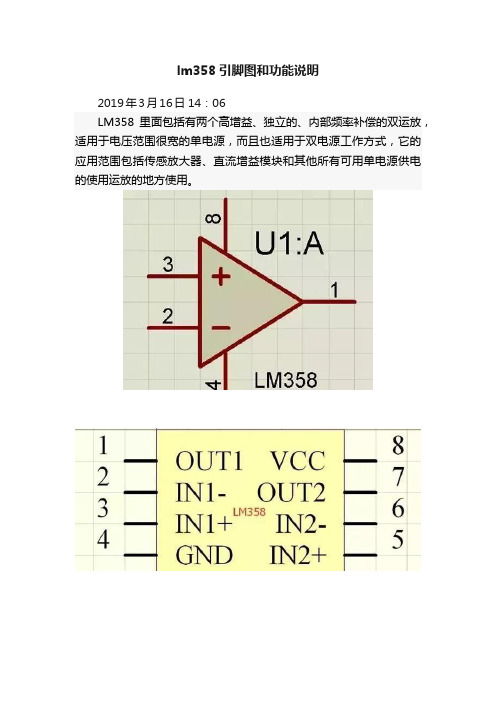
lm358引脚图和功能说明
2019年3月16日 14:06 LM358里面包括有两个高增益、独立的、内部频率补偿的双运放,适用于电压范围很宽的单电源,而且也适用于双电源工作方式,它的应用范围包括传感放大器、直流增益模块和其他所有可用单电源供电的使用运放的地方使用。
〈lm358引脚图及引脚功能〉
LM358是一款双运放,它的管脚很简单:8脚是正电源;4脚是负电源(双电源工作时)或地(单电源工作时); 1、2、3脚是一个运放通道,1脚是输出端,2脚是反相输入端,3脚是同相输入端;5、6、7脚为另一运放通道,7脚是输出端,6脚是反相输入端,5脚是同相输入端.如下图——
向左转|向右转
LM358封装有塑封8引线双列直插式和贴片式两种。
LM358的特点:
. 内部频率补偿
. 低输入偏流
. 低输入失调电压和失调电流
. 共模输入电压范围宽,包括接地
. 差模输入电压范围宽,等于电源电压范围
. 直流电压增益高(约100dB)
. 单位增益频带宽(约1MHz)
. 电源电压范围宽:单电源(3—30V);
. 双电源(±1.5 一±15V)
. 低功耗电流,适合于电池供电
. 输出电压摆幅大(0 至Vcc-1.5V)
2019年3月16日 14:06。
ST LMV321-LMV358-LMV324 数据手册
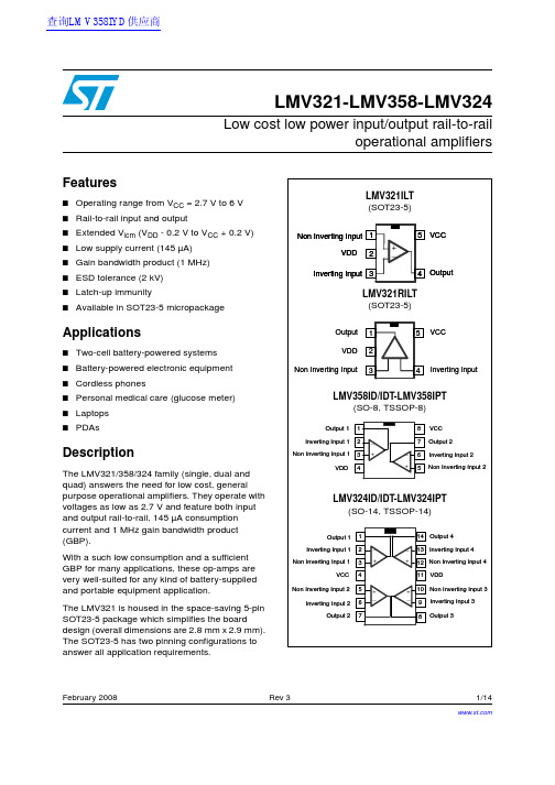
February 2008 Rev 31/14LMV321-LMV358-LMV324Low cost low power input/output rail-to-railoperational amplifiersFeatures■Operating range from V CC = 2.7V to 6V ■Rail-to-rail input and output■Extended V icm (V DD - 0.2V to V CC + 0.2V)■Low supply current (145µA)■Gain bandwidth product (1MHz)■ESD tolerance (2kV)■Latch-up immunity■Available in SOT23-5 micropackageApplications■Two-cell battery-powered systems ■Battery-powered electronic equipment ■Cordless phones■Personal medical care (glucose meter)■Laptops ■PDAsDescriptionThe LMV321/358/324 family (single, dual and quad) answers the need for low cost, general purpose operational amplifiers. They operate with voltages as low as 2.7V and feature both input and output rail-to-rail, 145µA consumption current and 1MHz gain bandwidth product (GBP).With a such low consumption and a sufficient GBP for many applications, these op-amps are very well-suited for any kind of battery-supplied and portable equipment application.The LMV321 is housed in the space-saving 5-pin SOT23-5 package which simplifies the board design (overall dimensions are 2.8mm x 2.9mm). The SOT23-5 has two pinning configurations to answer all application requirements.查询LMV358IYD供应商Absolute maximum ratings and operating conditions LMV321-LMV358-LMV3242/141 Absolute maximum ratings and operating conditionsTable 1.Absolute maximum ratingsSymbol ParameterValue Unit V CC Supply voltage (1)1.All voltage values, except differential voltage are with respect to network terminal.7V V id Differential input voltage (2)2.Differential voltages are the non-inverting input terminal with respect to the inverting input terminal. IfV id >±1V , the maximum input current must not exceed ±1mA. In this case (V id > ±1V), an input series resistor must be added to limit input current.±1V V in Input voltageV DD -0.3 to V CC +0.3V T oper Operating free air temperature range -40 to + 125°C T stg Storage temperature-65 to +150°C T jMaximum junction temperature150°CR thjaThermal resistance junction to ambient (3)SOT23-5SO-8SO-14TSSOP8TSSOP143.Short-circuits can cause excessive heating. Destructive dissipation can result from simultaneous short-circuits on all amplifiers. All values are typical.250125103120100°C/WR thjcThermal resistance junction to case (3)SOT23-5SO-8SO-14TSSOP8TSSOP148140313732°C/WESDHBM: human body model (4)4.Human body model: A 100pF capacitor is charged to the specified voltage, then discharged through a1.5k Ω resistor between two pins of the device. This is done for all couples of connected pin combinations while the other pins are floating.2kV MM: machine model (5)5.Machine model: A 200pF capacitor is charged to the specified voltage, then discharged directly betweentwo pins of the device with no external series resistor (internal resistor < 5Ω). This is done for all couples of connected pin combinations while the other pins are floating.200V CDM: charged device model (6)6.Charged device model: all pins and the package are charged together to the specified voltage and thendischarged directly to the ground through only one pin. This is done for all pins.No value specified for CDM on SOT23-5L package. The value is given for SO and TSSOP packages.1.5kV Lead temperature (soldering, 10sec)250°COutput short-circuit durationsee note (7)7.Short-circuits from the output to V CC can cause excessive heating. The maximum output current isapproximately 48mA, independent of the magnitude of V CC . Destructive dissipation can result from simultaneous short-circuits on all amplifiers.LMV321-LMV358-LMV324Absolute maximum ratings and operating conditions3/14Table 2.Operating conditionsSymbol ParameterValue Unit V CC Supply voltage2.7 to 6V V icm Common mode input voltage range (1)1.At 25°C, for 2.7 ≤ V CC ≤ 6V, V icm is extended to V DD - 0.2V, V CC + 0.2V.V DD -0.2 to V CC + 0.2V V icm Common mode input voltage range (2)2.In full temperature range, both rails can be reached when V CC does not exceed 5.5V.V DD to V CC V T operOperating free air temperature range-40 to + 125°CElectrical characteristics LMV321-LMV358-LMV3244/142 Electrical characteristicsTable 3.V CC = +2.7V, V DD = 0V, C L & R L connected to V CC /2, T amb = 25°C (unless otherwise specified)Symbol ParameterConditionsMin.Typ.Max.Unit V io Input offset voltage V icm = V out = V CC /2T min ≤ T amb ≤ T max0.136mV ΔV io Input offset voltage drift 2µV/°C I io Input offset current V icm = V out = V CC /2 (1)T min ≤ T amb ≤ T max 1925nA I ib Input bias currentV icm = V out = V CC /2(1)T min ≤ T amb ≤ T max 105085nA CMR Common mode rejection ratio 0 ≤ V icm ≤ V CC 5585dB SVR Supply voltage rejection ratio V icm = V CC /27080dB A vdLarge signal voltage gainV out = 0.5V to 2.2V R L = 10k ΩR L = 2k Ω807010088dBV OHHigh level output voltageV id = 100mVT min ≤ T amb ≤ T max R L = 10k ΩR L = 2k Ω 2.62.55 2.652.6VV OLLow level output voltageV id = -100mVT min ≤ T amb ≤ T max R L = 10k ΩR L = 2k Ω155090100mVI oOutput current Output source current V id = 100mV , V O = V DD Output sink currentV id = -100mV , V O = V CC 554646mAI CC Supply current (per amplifier)V out = V CC /2A VCL = 1, no load T min ≤ T amb ≤ T max 145200230µAGBP Gain bandwidth product R L = 10k Ω, C L = 100pF ,f = 100kHz1MHz SR Slew rate R L = 600Ω, C L = 100pF ,A V = 10.35V/µs φm Phase margin R L = 600Ω, C L = 100pF 44Degrees en Input voltage noise 40nV/√Hz THDT otal harmonic distortion0.01%1.Maximum values include unavoidable inaccuracies of the industrial tests.LMV321-LMV358-LMV324Electrical characteristics5/14Table 4.V CC = +5V, V DD = 0V, C L & R L connected to V CC /2, T amb = 25°C (unless otherwise specified)Symbol ParameterConditionsMin.Typ.Max.Unit V io Input offset voltage V icm = V out = V CC /2T min ≤ T amb ≤ T max0.136mV ΔV io Input offset voltage drift 2µV/°C I io Input offset current V icm = V out = V CC /2 (1)T min ≤ T amb ≤ T max 1925nA I ib Input bias currentV icm = V out = V CC /2(1)T min ≤ T amb ≤ T max 166395nA CMR Common mode rejection ratio 0 ≤ V icm ≤ V CC 6595dB SVR Supply voltage rejection ratio V icm = V CC /27090dB A vdLarge signal voltage gainV out = 0.5V to 4.5V R L = 10k ΩR L = 2k Ω85779793dBV OHHigh level output voltageV id = 100mVT min ≤ T amb ≤ T max R L = 10k ΩR L = 2k Ω 4.854.8 4.954.91VV OLLow level output voltageV id = -100mVT min ≤ T amb ≤ T max R L = 10k ΩR L = 2k Ω4080180200mVI oOutput current Output source current V id = 100mV , V O = V DD Output sink currentV id = -100mV , V O = V CC 774848mAI CC Supply current (per amplifier)V out = V CC /2A VCL = 1, no load T min ≤ T amb ≤ T max 162220250µAGBP Gain bandwidth product R L = 10k Ω, C L = 100pF ,f = 100kHz1.3MHz SR Slew rate R L = 600Ω, C L = 100pF ,A V = 10.45V/µs φm Phase margin R L = 600Ω, C L = 100pF 48Degrees en Input voltage noise 40nV/√Hz THDT otal harmonic distortion0.01%1.Maximum values include unavoidable inaccuracies of the industrial tests.Electrical characteristicsLMV321-LMV358-LMV3246/14Figure 1.Supply current/amplifier vs. supplyFigure 2.Input bias current vs. temperatureFigure 3.Input bias current vs. temperature Figure 4.Common mode rejection vs.Figure 5.Common mode rejection vs. Figure 6.Supply voltage rejection vs.LMV321-LMV358-LMV324Electrical characteristics7/14Figure 9.Supply voltage rejection vs.Figure 10.Output current vs. output voltagePackage information LMV321-LMV358-LMV3248/143 Package informationIn order to meet environmental requirements, STMicroelectronics offers these devices inECOPACK ® packages. These packages have a lead-free second level interconnect. The category of second level interconnect is marked on the package and on the inner box label, in compliance with JEDEC Standard JESD97. The maximum ratings related to soldering conditions are also marked on the inner box label. ECOPACK is an STMicroelectronics trademark. ECOPACK specifications are available at: .3.1 SOT23-5 package informationTable 5.SOT23-5 package mechanical dataRef.DimensionsMillimetersMils Min.Typ.Max.Min.Typ.Max.A 0.90 1.4535.457.1A10.000.150.00 5.9A20.90 1.3035.451.2b 0.350.5013.719.7C 0.090.20 3.57.8D 2.80 3.00110.2118.1E 2.60 3.00102.3118.1E1 1.501.7559.068.8e 0.9537.4e1 1.974.8L0.350.5513.721.6LMV321-LMV358-LMV324Package information9/143.2 SO-8 package informationTable 6.SO-8 package mechanical dataRef.DimensionsMillimetersInches Min.Typ.Max.Min.Typ.Max.A 1.750.069A10.100.250.0040.010A2 1.250.049b 0.280.480.0110.019c 0.170.230.0070.010D 4.80 4.90 5.000.1890.1930.197E 5.80 6.00 6.200.2280.2360.244E1 3.803.904.000.1500.1540.157e 1.270.050h 0.250.500.0100.020L 0.40 1.270.0160.050k 1°8°1°8°ccc0.100.004Package information LMV321-LMV358-LMV32410/143.3 TSSOP8 package informationTable 7.TSSOP8 package mechanical dataRef.DimensionsMillimetersInches Min.Typ.Max.Min.Typ.Max.A 1.20.047A10.050.150.0020.006A20.80 1.001.050.0310.0390.041b 0.190.300.0070.012c 0.090.200.0040.008D 2.90 3.00 3.100.1140.1180.122E 6.20 6.40 6.600.2440.2520.260E1 4.304.40 4.500.1690.1730.177e 0.650.0256k 0°8°0°8°L 0.450.600.750.0180.0240.030L110.039aaa0.10.004LMV321-LMV358-LMV324Package information11/143.4 SO-14 package informationTable 8.SO-14 package mechanical dataRef.DimensionsMillimetersInches Min.Typ.Max.Min.Typ.Max.A 1.750.068a10.10.20.0030.007a2 1.650.064b 0.350.460.0130.018b10.190.250.0070.010C 0.50.019c145° (typ.)D 8.558.750.3360.344E 5.8 6.20.2280.244e 1.270.050e37.620.300F 3.8 4.00.1490.157G 4.6 5.30.1810.208L 0.5 1.270.0190.050M 0.680.026S8° (max.)Package information LMV321-LMV358-LMV32412/143.5 TSSOP14 package informationFigure 18.TSSOP14 package mechanical dataRef.DimensionsMillimetersInches Min.Typ.Max.Min.Typ.Max.A 1.20.047A10.050.150.0020.0040.006A20.81 1.050.0310.0390.041b 0.190.300.0070.012c 0.090.200.0040.0089D 4.95 5.10.1930.1970.201E 6.2 6.4 6.60.2440.2520.260E1 4.34.4 4.480.1690.1730.176e 0.65 BSC0.0256 BSCK 0°8°0°8°L10.450.600.750.0180.0240.030LMV321-LMV358-LMV324Ordering information13/144 Ordering information5 Revision historyTable 9.Order codesOrder codeTemperature rangePackage Packaging Marking LMV321ILT -40°C, +125 °CSOT23-5T ape & reel K177LMV321RILT K176LMV321IYLT (1)SOT23-5(Automotive grade)T ape & reel K180LMV321RIYLT (1)K185LMV358ID LMV358IDT SO-8T ube or tape & reel LMV358LMV358IYD (1)LMV358IYDT (1)SO-8(Automotive grade)T ube or tape & reel LMV358IY LMV358IPT TSSOP8T ape & reel MV358LMV358IYPT (1)TSSOP8(Automotive grade)T ape & reel K181Y LMV324ID LMV324IDT SO-14T ube or tape & reel LMV324LMV324IYD (1)LMV324IYDT (1)SO-14(Automotive grade)T ube or tape & reel V324Y LMV324IPT TSSOP14T ape & reel MV324LMV324IYPT (1)TSSOP14(Automotive grade)T ape & reelV324IY1.Qualification and characterization according to AEC Q100 and Q003 or equivalent, advanced screening according to AECQ001 & Q 002 or equivalent are on-going.Table 10.Document revision historyDate RevisionChanges1-Dec-20051First release - Products in full production.25-May-20072Added automotive grade part numbers to order codes table. Moved ordercodes table to Section 4 on page 13.20-Feb-20083Added Figure 12: Noise versus frequency on page 7.Updated presentation of package information.Corrected footnote for automotive grade part numbers in order codes table.LMV321-LMV358-LMV32414/14Please Read Carefully:Information in this document is provided solely in connection with ST products. STMicroelectronics NV and its subsidiaries (“ST”) reserve the right to make changes, corrections, modifications or improvements, to this document, and the products and services described herein at any time, without notice.All ST products are sold pursuant to ST’s terms and conditions of sale.Purchasers are solely responsible for the choice, selection and use of the ST products and services described herein, and ST assumes no liability whatsoever relating to the choice, selection or use of the ST products and services described herein.No license, express or implied, by estoppel or otherwise, to any intellectual property rights is granted under this document. If any part of this document refers to any third party products or services it shall not be deemed a license grant by ST for the use of such third party products or services, or any intellectual property contained therein or considered as a warranty covering the use in any manner whatsoever of such third party products or services or any intellectual property contained therein.UNLESS OTHERWISE SET FORTH IN ST’S TERMS AND CONDITIONS OF SALE ST DISCLAIMS ANY EXPRESS OR IMPLIED WARRANTY WITH RESPECT TO THE USE AND/OR SALE OF ST PRODUCTS INCLUDING WITHOUT LIMITATION IMPLIED WARRANTIES OF MERCHANTABILITY, FITNESS FOR A PARTICULAR PURPOSE (AND THEIR EQUIVALENTS UNDER THE LAWS OF ANY JURISDICTION), OR INFRINGEMENT OF ANY PATENT, COPYRIGHT OR OTHER INTELLECTUAL PROPERTY RIGHT. UNLESS EXPRESSLY APPROVED IN WRITING BY AN AUTHORIZED ST REPRESENTATIVE, ST PRODUCTS ARE NOT RECOMMENDED, AUTHORIZED OR WARRANTED FOR USE IN MILITARY, AIR CRAFT, SPACE, LIFE SAVING, OR LIFE SUSTAINING APPLICATIONS, NOR IN PRODUCTS OR SYSTEMS WHERE FAILURE OR MALFUNCTION MAY RESULT IN PERSONAL INJURY, DEATH, OR SEVERE PROPERTY OR ENVIRONMENTAL DAMAGE. ST PRODUCTS WHICH ARE NOT SPECIFIED AS "AUTOMOTIVE GRADE" MAY ONLY BE USED IN AUTOMOTIVE APPLICATIONS AT USER’S OWN RISK.Resale of ST products with provisions different from the statements and/or technical features set forth in this document shall immediately void any warranty granted by ST for the ST product or service described herein and shall not create or extend in any manner whatsoever, any liability of ST.ST and the ST logo are trademarks or registered trademarks of ST in various countries.Information in this document supersedes and replaces all information previously supplied.The ST logo is a registered trademark of STMicroelectronics. All other names are the property of their respective owners.© 2008 STMicroelectronics - All rights reservedSTMicroelectronics group of companiesAustralia - Belgium - Brazil - Canada - China - Czech Republic - Finland - France - Germany - Hong Kong - India - Israel - Italy - Japan - Malaysia - Malta - Morocco - Singapore - Spain - Sweden - Switzerland - United Kingdom - United States of America。
LM358技术参数

下载:lm358中文资料LM358是常用的双运放,这里我们介绍一下他的一些资料以及简单电路应用等,有什么问题请去电子论坛.简介:LM358里面包括有两个高增益、独立的、内部频率补偿的双运放,适用于电压范围很宽的单电源,而且也适用于双电源工作方式,它的应用范围包括传感放大器、直流增益模块和其他所有可用单电源供电的使用运放的地方使用。
〈lm358引脚图及引脚功能〉LM358封装有塑封8引线双列直插式和贴片式两种。
LM358的特点:.内部频率补偿.低输入偏流.低输入失调电压和失调电流.共模输入电压范围宽,包括接地.差模输入电压范围宽,等于电源电压范围.直流电压增益高(约100dB).单位增益频带宽(约1MHz).电源电压范围宽:单电源(3—30V);.双电源(±1.5一±15V).低功耗电流,适合于电池供电.输出电压摆幅大(0至Vcc-1.5V)图1DIP塑封引脚图引脚功能图2圆形金属壳封装管脚图图3内部电路原理图lm358中文资料LM358内部包括有两个独立的、高增益、内部频率补偿的双运算放大器,适合于电源电压范围很宽的单电源使用,也适用于双电源工作模式,在推荐的工作条件下,电源电流与电源电压无关。
它的使用范围包括传感放大器、直流增益模组,音频放大器、工业控制、DC增益部件和其他所有可用单电源供电的使用运算放大器的场合。
LM358的封装形式有塑封8引线双列直插式和贴片式。
特性(Features):*内部频率补偿。
*直流电压增益高(约100dB)。
*单位增益频带宽(约1MHz)。
*电源电压范围宽:单电源(3—30V);双电源(±1.5一±15V)。
*低功耗电流,适合于电池供电。
*低输入偏流。
*低输入失调电压和失调电流。
*共模输入电压范围宽,包括接地。
*差模输入电压范围宽,等于电源电压范围。
*输出电压摆幅大(0至Vcc-1.5V)。
参数输入偏置电流45nA输入失调电流50nA输入失调电压2.9mV输入共模电压最大值VCC~1.5V共模抑制比80dB电源抑制比100dBLM358应用电路图:图15功率放大器外围电路图21可调增益仪表放大器图22直流放大器图24桥式电流放大器图25引用差分输入信号图26直流差动放大器。
lm358工作原理

lm358工作原理
LM358是一种双运放集成电路,由电源引脚、输入电阻、电
流源、微分放大器、共模放大器、输出级以及补偿电路等组成。
其工作原理如下:
1. 电源引脚:LM358通常需要连接正负电源以供电。
正电源
通常连接到VCC引脚,负电源通常连接到GND引脚。
2. 输入电阻:当信号输入到LM358时,输入电阻负责将输入
信号电流转换为电压。
这样可以确保输入信号准确地进入微分放大器和共模放大器。
3. 微分放大器:在LM358内部,微分放大器是双运放的核心
部分。
它主要用于放大和处理差分模式信号。
微分放大器由一个差分对和一个放大器级组成,差分对负责放大输入信号的差模部分,放大器级则用于进一步放大。
4. 共模放大器:共模放大器是用于放大输入信号的共模部分的辅助电路。
这可以提高输入信号的抗干扰性能并保持输入信号的稳定性。
5. 输出级:输出级负责放大微分放大器和共模放大器的输出信号,并将其提供给外部电路。
6. 补偿电路:由于操作放大器时产生的不确定性和偏差,为了提高放大器的性能,LM358通常配备了补偿电路。
补偿电路
可以减小非线性失真,并提高工作稳定性。
综上所述,LM358通过输入电阻、微分放大器、共模放大器、输出级和补偿电路等部分的协同工作,完成对输入信号的放大和处理,从而实现预期的功能。
- 1、下载文档前请自行甄别文档内容的完整性,平台不提供额外的编辑、内容补充、找答案等附加服务。
- 2、"仅部分预览"的文档,不可在线预览部分如存在完整性等问题,可反馈申请退款(可完整预览的文档不适用该条件!)。
- 3、如文档侵犯您的权益,请联系客服反馈,我们会尽快为您处理(人工客服工作时间:9:00-18:30)。
IMPORTANT NOTICE
Texas Instruments and its subsidiaries (TI) reserve the right to make changes to their products or to discontinue any product or service without notice, and advise customers to obtain the latest version of relevant information to verify, before placing orders, that information being relied on is current and complete. All products are sold subject to the terms and conditions of sale supplied at the time of order acknowledgement, including those pertaining to warranty, patent infringement, and limitation of liability.
TI warrants performance of its semiconductor products to the specifications applicable at the time of sale in accordance with TI’s standard warranty. Testing and other quality control techniques are utilized to the extent TI deems necessary to support this warranty. Specific testing of all parameters of each device is not necessarily performed, except those mandated by government requirements.
CERTAIN APPLICATIONS USING SEMICONDUCTOR PRODUCTS MAY INVOLVE POTENTIAL RISKS OF DEATH, PERSONAL INJURY, OR SEVERE PROPERTY OR ENVIRONMENTAL DAMAGE (“CRITICAL APPLICATIONS”). TI SEMICONDUCTOR PRODUCTS ARE NOT DESIGNED, AUTHORIZED, OR WARRANTED TO BE SUITABLE FOR USE IN LIFE-SUPPORT DEVICES OR SYSTEMS OR OTHER CRITICAL APPLICATIONS. INCLUSION OF TI PRODUCTS IN SUCH APPLICATIONS IS UNDERSTOOD TO BE FULLY AT THE CUSTOMER’S RISK.
In order to minimize risks associated with the customer’s applications, adequate design and operating safeguards must be provided by the customer to minimize inherent or procedural hazards.
TI assumes no liability for applications assistance or customer product design. TI does not warrant or represent that any license, either express or implied, is granted under any patent right, copyright, mask work right, or other intellectual property right of TI covering or relating to any combination, machine, or process in which such semiconductor products or services might be or are used. TI’s publication of information regarding any third party’s products or services does not constitute TI’s approval, warranty or endorsement thereof.
Copyright © 2000, Texas Instruments Incorporated。
