PLL801-5840Y中文资料
明德扬 MP801 开发板说明书

明德扬MP801开发板说明书修订日期:20200409 版本:v5.0目录明德扬MP801开发板说明书 (1)一、明德扬MP801开发板介绍 (3)二、开发板硬件介绍 (4)1、FPGA芯片 (4)2、数码管和LED灯 (4)3、拨码开关 (5)4、普通按键和复位按键 (5)5、温度传感器 (6)6、EEPROM存储器 (6)7、VGA接口 (7)8、锋鸣器 (7)9、SDRAM存储器 (8)10、千兆网口 (8)11、USB串口 (9)12、AD9709与AD9280 (9)13、基它扩展口 (10)三、配套学习资料 (10)四、配套案例列举 (11)五、技术支持 (12)六、更多帮助 (12)一、明德扬MP801开发板介绍MP801开发板是基于altera Cyclone IV 系列FPGA自主研发的高校级教学开发板,6层板制作工艺,尺寸为130mm*100mm。
该板非常适合初学者以及项目进阶训练,明德扬为此提供大量的配套练习,以及提供完善的售后服务。
从简单的led 到复杂的SDRAM等一应俱全,其中板载EP4CE15F23C8,拥有15K逻辑资源,504K bit ram资源,且板载3片128M bit SDRAM,适合存储大容量的数据;并且拥有125Mhz 双通道转换速率的高速并行DA芯片AD9709和32Mhz 转换速率的高速并行AD芯片AD9280,编程简单,适用做算法验证;并且采用64M spi flash存储器存储程序,满足开发需求。
在此,明德扬希望您早日掌握FPGA编程技术,学有所成。
二、开发板硬件介绍1、FPGA芯片Altera Cyclone IV系列芯片,采用型号为:EP4CE15F23C8,逻辑单元:15408,用户可用IO:6272,内部存储器:516096,PLL:4,M9K:112,可通过低功耗和成本实现较高的功能性。
2、数码管和LED灯开发板板载红色8个数码管,采用动态显示的方式和FPGA连接,其中数码管采用共阳极数码管,开发板led电路采用上拉接法,板载8个绿色的led。
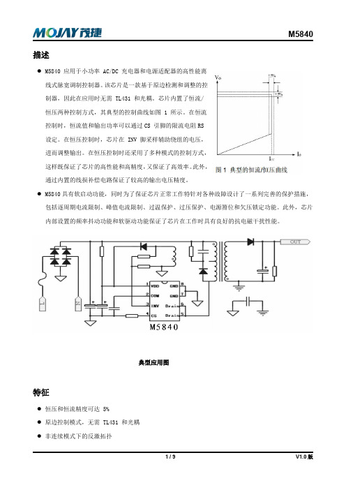
M5840-V2.0规格书(中文)
恒流工作
M5840 的恒压/恒流特征曲线如图 1 所示。M5840 被设计应用于工作在非连续模式下的反激式系统中。
在正常工作时,当 INV 电压低于内部 2.0V 的基准电压好时,系统工作在恒流模式,否则系统工作在恒压
模式。当次级输出电流达到了系统设定的最大电流时,系统就进入恒流模式,并且会引起输出电压的下降。
电气参数 (Ta=25oC, 其余情况会做说明)
(如无特殊说明, VIN=12V(注 1), TA=25℃)
参数
启动电流
工作电流
进入欠压锁定的阈值电压 退出欠压锁定的阈值电压 过压保护的阈值电压 电源箝位电压 内置 MOS 管耐压值 MOS 管导通电阻值 前沿消隐时间 过流保护阈值 过流保护延迟 输入阻抗 软启动时间 正常工作频率 启动频率 频率抖动幅度 误差放大器的输入基准电压 误差放大器的直流增益 线损补偿最大电流 输出低电平
由于 TDemag 与电感的大小成反比,因此,电感 LP 和 FSW 的乘积为一定值,从而限制了最大的输 出功率,避免了系统进入连续工作模式。
电流检测和前沿消隐 M5840 采样功率 MOSFET 上的电流是通过 CS 来实现的。 M5840 不仅设计了逐周期的电流限制,而
且设计了峰值电流限制,最大的峰值电流电压为 0.9V。因此,MOSFET 上最大的峰值电流为:
随着输出电压的下降,反馈电压也跟着下降,芯片内部的 VCO 将
会调整开关的频率,以使输出功率保持和输出电压成正比,其结
果就是使输出电流保持恒定。这就是恒流的原理。在恒流模式下,
无论输出电压如何变化,输出电流为一常数。在作为充电器应用
时,先是恒流充电直到接近电池充饱的状态,随后再进行恒压充
电。在 M5840 中, 恒流值和最大输出功率可以通过外部的限流
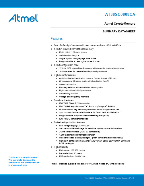
Atmel AT88SC0808CA 密码存储芯片数据手册说明书
AT88SC0808CAAtmel CryptoMemorySUMMARY DATASHEETFeatures ∙ One of a family of devices with user memories from 1-Kbit to 8-Kbits ∙8-Kbit (1-Kbyte) EEPROM user memory∙ Eight 1-Kbit (128-byte) zones ∙ Self-timed write cycle∙ Single byte or 16-byte page write mode ∙ Programmable access rights for each zone∙ 2-Kbit configuration zone∙ 37-byte OTP (One-Time Programmable) area for user-defined codes ∙ 160-byte area for user-defined keys and passwords ∙High security features∙ 64-bit mutual authentication protocol (under license of ELVA) ∙ Cryptographic Message Authentication Codes (MAC) ∙ Stream encryption∙ Four key sets for authentication and encryption ∙ Eight sets of two 24-bit passwords ∙ Anti-tearing function∙ Voltage and frequency monitors∙Smart card features∙ ISO 7816 Class B (3V) operation∙ ISO 7816-3 asynchronous T=0 Protocol (Gemplus ®Patent) * ∙ Multiple zones, key sets and passwords for multi-application use ∙ Synchronous 2-wire serial interface for faster device initialization * ∙ Programmable 8-byte answer-to-reset register (ATR) ∙ISO 7816-2 compliant modules∙Embedded application features∙ Low voltage supply: 2.7V – 3.6V∙ Secure nonvolatile storage for sensitive system or user information ∙ 2-wire serial interface (TWI, 5V compatible) ∙ 1.0MHz compatibility for fast operation∙ Standard 8-lead plastic packages, green compliant (exceeds RoHS)∙Same pin configuration as Atmel ®AT24CXXX Serial EEPROM in SOIC and PDIP packages∙High reliability∙ Endurance: 100,000 cycles ∙ Data retention: 10 years ∙ ESD protection: 2,000V min* Note: Modules available with either T=0 / 2-wire modes or 2-wire mode onlyThis is a summary document. The complete document is available on the Atmel website at .AT88SC0808CA [Summary DATASHEET]Atmel-5204IS-CryptoMem-AT88SC0808CA-Datasheet-Summary_0720152Table 1. Pin AssignmentsPin Configuration123487658-lead SOIC, PDIPNC NCNC GNDV CCNC SCL SDA8-lead TSSOPNCV CC 81NC C N 72NCK L C 63GND 54SDA 12348765SDA GND CLK V CC8-lead Ultra Thin Mini-MAP (MLP 2x3)Bottom ViewNCNC NC NC TWI Smart Card ModuleV C C =C1 NC =C2 SCL/CLK=C3NC=C4C5=GND C6=NC C7=S D A /IO C8=NCISO Smart Card ModuleV C C =C1 RST=C2 SCL/CLK=C3NC=C4C5=GND C6=NC C7=S D A /IO C8=NCAT88SC0808CA [Summary DATASHEET]Atmel-5204IS-CryptoMem-AT88SC0808CA-Datasheet-Summary_07201531. DescriptionThe Atmel AT88SC0808CA member of the Atmel CryptoMemory ®family is a high-performance secure memory providing 8-Kbit of user memory with advanced security and cryptographic features built in. The user memory is divided into eight128-byte zones, each of which may be individually set with different security access rights or effectively combined together to provide space for one to eight data files. The AT88SC0808CA features an enhanced command set that allows directcommunication with microcontroller hardware 2-wire interface thereby allowing for faster firmware development with reduced code space requirements.1.1 Smart Card ApplicationsThe AT88SC0808CA provides high security, low cost, and ease of implementation without the need for a microprocessor operating system. The embedded cryptographic engine provides for dynamic, symmetric-mutual authentication between the device and host, as well as performing stream encryption for all data and passwords exchanged between the device and host. Up to four unique key sets may be used for these operations. The AT88SC0808CA offers the ability to communicate with virtually any smart card reader using the asynchronous T = 0 protocol (Gemplus Patent) defined in ISO 7816-3.1.2 Embedded ApplicationsThrough dynamic, symmetric-mutual authentication, data encryption, and the use of cryptographic Message Authentication Codes (MAC), the AT88SC0808CA provides a secure place for storage of sensitive information within a system. With its tamper detection circuits, this information remains safe even under attack. A 2-wire serial interface running at speeds up to 1.0MHz provides fast and efficient communications with up to 15 individually addressable devices. The AT88SC0808CA is available in industry standard 8-lead packages with the same familiar pin configuration as Atmel AT24CXXX Serial EEPROM devices. Note:Does not apply to either the TSSOP or the Ultra Thin Mini-Map pinoutsFigure 1-1. Block DiagramV CC GNDSCL/CLK SDA/IORSTAT88SC0808CA [Summary DATASHEET]Atmel-5204IS-CryptoMem-AT88SC0808CA-Datasheet-Summary_07201542. Connection DiagramFigure 2-1. Connection Diagram3.Pin Descriptions3.1Supply Voltage (V CC )The V CC input is a 2.7V to 3.6V positive voltage supplied by the host.3.2 Clock (SCL/CLK)When using the asynchronous T = 0 protocol, the CLK (SCL) input provides the device with a carrier frequency f . The nominal length of one bit emitted on I/O is defined as an “elementary time unit” (ETU) and is equal to 372/ f .When using the synchronous protocol, data clocking is done on the positive edge of the clock when writing to the device and on the negative edge of the clock when reading from the device.3.3 Reset (RST)The AT88SC0808CA provides an ISO 7816-3 compliant asynchronous answer-to-reset (ATR) sequence. Upon activation of the reset sequence, the device outputs bytes contained in the 64-bit ATR register. An internal pull-up on the RST input pad allows the device to operate in synchronous mode without bonding RST. The AT88SC0808CA does not support an ATR sequence in the synchronous mode of operation.3.4 Serial Data (SDA/IO)The SDA/IO pin is bidirectional for serial data transfer. This pin is open-drain driven and may be wired with any number of other open-drain or open-collector devices. An external pull-up resistor should be connected between SDA/IO and V CC . The value of this resistor and the system capacitance loading the SDA/IO bus will determine the rise time of SDA/IO. This rise time will determine the maximum frequency during read operations. Low value pull-up resistors will allow higher frequency operations while drawing higher average power supply current. SDA/IO information applies to both asynchronous andsynchronous protocols.AT88SC0808CA [Summary DATASHEET]Atmel-5204IS-CryptoMem-AT88SC0808CA-Datasheet-Summary_07201554. Absolute Maximum Ratings**Notice:Stresses beyond those listed under “AbsoluteMaximum Ratings” may cause permanent damage to the device. This is a stress rating only and functional operation of the device at these or any other condition beyond those indicated in the operational sections of this specification is not implied. Exposure to absolute maximum rating conditions for extended periods of time may affect device reliability.Table 4-1.DC CharacteristicsApplicable over recommended operating range from V CC = +2.7 to 3.6V, T AC = -40°C to +85°C (unless otherwise noted)Note:1. To prevent latch up conditions from occurring during power up of the AT88SC0808CA, V CC must be turned onbefore applying V IH . For powering down, V IH must be removed before turning V CC off.AT88SC0808CA [Summary DATASHEET]Atmel-5204IS-CryptoMem-AT88SC0808CA-Datasheet-Summary_0720156Table 4-2.AC CharacteristicsApplicable over recommended operating range from V CC = +2.7 to 3.6V, T AC = -40°C to +85°C, CL = 30pF (unless otherwise noted)5.Device Operations for Synchronous Protocols5.1Clock and Data TransitionsThe SDA pin is normally pulled high with an external device. Data on the SDA pin may change only during SCL low time periods (see Figure 5-3 on page 8). Data changes during SCL high periods will indicate a start or stop condition as defined below.5.1.1 Start conditionA high-to-low transition of SDA with SCL high defines a start condition which must precede all commands (see Figure 5-4 on page 8).5.1.2 Stop conditionA low-to-high transition of SDA with SCL high defines a stop condition. After a read sequence, the stop condition will place the EEPROM in a standby power mode (see Figure 5-4 on page 8).5.1.3 AcknowledgeAll addresses and data words are serially transmitted to and from the EEPROM in 8-bit words. The EEPROM sends a zero to acknowledge that it has received each word. This happens during the ninth clock cycle (see Figure 5-5 on page 8).AT88SC0808CA [Summary DATASHEET]Atmel-5204IS-CryptoMem-AT88SC0808CA-Datasheet-Summary_07201575.2 Memory ResetAfter an interruption in communication due protocol errors, power loss or any reason, perform "Acknowledge Polling" to properly recover from the condition. Acknowledge polling consists of sending a start condition followed by a valid CryptoMemory command byte and determining if the device responded with an acknowledge. Figure 5-1. Bus Time for 2-wire Serial CommunicationsSCL: Serial Clock, SDA: Serial Data I/OFigure 5-2. Write Cycle TimingSCL: Serial Clock, SDA: Serial Data I/ONote:The write cycle time t WR is the time from a valid stop condition of a write sequence to the end of the internal clear/write cycleSCLSDA INSDA OUTAT88SC0808CA [Summary DATASHEET]Atmel-5204IS-CryptoMem-AT88SC0808CA-Datasheet-Summary_0720158Figure 5-3. Data ValidityFigure 5-4. START and STOP DefinitionsFigure 5-5. Output AcknowledgeST ARTACKNOWLEDGESCLDAT A INDAT A OUT189AT88SC0808CA [Summary DATASHEET]Atmel-5204IS-CryptoMem-AT88SC0808CA-Datasheet-Summary_07201596.Device Architecture6.1User ZonesThe EEPROM user memory is divided into eight zones of 1-Kbit each. Multiple zones allow for storage of different types of data or files in different zones. Access to user zones is permitted only after meeting proper security requirements. These security requirements are user definable in the configuration memory during device personalization. If the same security requirements are selected for multiple zones, then these zones may effectively be accessed as one larger zone. Figure 6-1. User Zones7. Control LogicAccess to the user zones occur only through the control logic built into the device. This logic is configurable through access registers, key registers and keys programmed into the configuration memory during device personalization. Also implemented in the control logic is a cryptographic engine for performing the various higher-level security functions of the device.AT88SC0808CA [Summary DATASHEET]Atmel-5204IS-CryptoMem-AT88SC0808CA-Datasheet-Summary_072015108. Configuration MemoryThe configuration memory consists of 2048 bits of EEPROM memory used for storage of passwords, keys, codes, and also used for definition of security access rights for the user zones. Access rights to the configuration memory are defined in the control logic and are not alterable by the user after completion of personalization. Figure 8-1. Configuration Memory9. Security FusesThere are three fuses on the device that must be blown during the device personalization process. Each fuse locks certain portions of the configuration zone as OTP (One-Time Programmable) memory. Fuses are designed for the modulemanufacturer, card manufacturer and card issuer and should be blown in sequence, although all programming of the device and blowing of the fuses may be performed at one final step.10. Communication Security ModesCommunications between the device and host operate in three basic modes. Standard mode is the default mode for thedevice after power-up. Authentication mode is activated by a successful authentication sequence. Encryption mode isactivated by a successful encryption activation following a successful authentication.Table 10-1. Communication Security Modes(1)Note: 1. Configuration data include viewable areas of the configuration zone except the passwords:•MDC: Modification Detection Code•MAC: Message Authentication Code11. Security Options11.1 Anti-TearingIn the event of a power loss during a write cycle, the integrity of the device’s stored data is recoverable. This function isoptional: the host may choose to activate the anti-tearing function, depending on application requirements. When anti-tearing is active, write commands take longer to execute, since more write cycles are required to complete them, and data is limited toa maximum of eight bytes for each write request.Data is written first into a buffer zone in EEPROM instead of the intended destination address, but with the same accessconditions. The data is then written in the required location. If this second write cycle is interrupted due to a power loss, the device will automatically recover the data from the system buffer zone at the next power-up. Non-volatile buffering of the data is done automatically by the device.During power-up in applications using anti-tearing, the host is required to perform ACK polling in the event that the deviceneeds to carry out the data recovery process.11.2 Write LockIf a user zone is configured in the write lock mode, the lowest address byte of an 8-byte page constitutes a write access byte for the bytes of that page.Example: The write lock byte at $080 controls the bytes from $081 to $087Figure 11-1. Write Lock ExampleThe write lock byte itself may be locked by writing its least significant (rightmost) bit to “0”. Moreover, when write lock mode is activated, the write lock byte can only be programmed – that is, bits written to “0” cannot return to “1”.In the write lock configuration, write operations are limited to writing only one byte at a time. Attempts to write more than one byte will result in writing of just the first byte into the device.11.3 Password VerificationPasswords may be used to protect read and/or write access of any user zone. When a valid password is presented, it ismemorized and active until power is turned off, unless a new password is presented or RST becomes active. There are eight password sets that may be used to protect any user zone. Only one password is active at a time. Presenting the correct write password also grants read access privileges.11.4 Authentication ProtocolThe access to a user zone may be protected by an authentication protocol. Any one of four keys may be selected to use with a user zone.Authentication success is memorized and active as long as the chip is powered, unless a new authentication is initialized or RST becomes active. If the new authentication request is not validated, the card loses its previous authentication which must be presented again to gain access. Only the latest request is memorized. Figure 11-2. Password and Authentication OperationsNote:Authentication and password verification may be attempted at any time and in any order. Exceedingcorresponding authentication or password attempts trial limit renders subsequent authentication or password verification attempts futile.READ ACCESSWRITE ACCESS11.5 Cryptographic Message Authentication CodesAT88SC0808CA implements a data validity check function in the standard, authentication or encryption modes of operation.In the standard mode, data validity check is done through a Modification Detection Code (MDC), in which the host may read an MDC from the device in order to verify that the data sent was received correctly.In authentication and encryption modes, the data validity check becomes more powerful since it provides a bidirectional data integrity check and data origin authentication capability in the form of a Message Authentication Codes (MAC). Only thehost/device that carried out a valid authentication is capable of computing a valid MAC. While operating in the authentication or encryption modes, the use of MAC is required. For an ingoing command, if the device calculates a MAC different from the MAC transmitted by the host, not only is the command abandoned but the security privilege is revoked. A new authentication and/or encryption activation will be required to reactivate the MAC.11.6 EncryptionThe data exchanged between the device and the host during read, write and verify password commands may be encrypted to ensure data confidentiality.The issuer may choose to require encryption for a user zone by settings made in the configuration memory. Any one of four keys may be selected for use with a user zone. In this case, activation of the encryption mode is required in order to read/write data in the zone and only encrypted data will be transmitted. Even if not required, the host may still elect to activate encryption provided the proper keys are known.11.7 Supervisor ModeEnabling this feature allows the holder of one specific password to gain full access to all eight password sets, including the ability to change passwords.11.8 Modify ForbiddenNo write access is allowed in a user zone protected with this feature at any time. The user zone must be written during device personalization prior to blowing the security fuses.11.9 Program OnlyFor a user zones protected by this feature, data can only be programmed (bits change from a “1” to a “0”), but not erased (bi ts change from a “0” to a “1”).12. Protocol SelectionThe AT88SC0808CA supports two different communication protocols.∙ Smartcard Applications:Smartcard applications use ISO 7816-B protocol in asynchronous T = 0 mode for compatibility and interoperability with industry standard smartcard readers.∙ Embedded Applications:A 2-wire serial interface provides fast and efficient connectivity with other logic devices or microcontrollers.The power-up sequence determines establishes the communication protocol for use within that power cycle. Protocol selection is allowed only during power-up.12.1 Synchronous 2-wire Serial InterfaceThe synchronous mode is the default mode after power up. This is due to the presence of an internal pull-up on RST. For embedded applications using CryptoMemory in standard plastic packages, this is the only available communication protocol.∙ Power-up V CC , RST goes high also∙ After stable V CC , SCL(CLK) and SDA(I/O) may be driven∙ Once synchronous mode has been selected, it is not possible to switch to asynchronous mode without first poweringoff the deviceFigure 12-1. Synchronous 2-wire ProtocolNote: Five clock pulses must be sent before the first command is issued.V cc I/O-SDARST CLK-SCL1234512.2 Asynchronous T = 0 ProtocolThis power-up sequence complies to ISO 7816-3 for a cold reset in smart card applications.∙ V CC goes high; RST, I/O (SDA) and CLK (SCL) are low ∙ Set I/O (SDA) in receive mode ∙ Provide a clock signal to CLK (SCL) ∙RST goes high after 400 clock cyclesThe device will respond with a 64-bit ATR code, including historical bytes to indicate the memory density within the CryptoMemory family.Once asynchronous mode has been selected, it is not possible to switch to synchronous mode without first powering off the device.Figure 12-2. Asynchronous T = 0 Protocol (Gemplus Patent)13. Initial Device ProgrammingEnabling the security features of CryptoMemory requires prior personalization. Personalization entails setting up of desired access rights by zones, passwords and key values, programming these values into the configuration memory with verification using simple write and read commands, and then blowing fuses to lock this information in place.Gaining access to the configuration memory requires successful presentation of a secure (or transport) code. The initial signature of the secure (transport) code for the AT88SC0808CA device is $22 E8 3F. This is the same as the Write 7 password. The user may elect to change the signature of the secure code anytime after successful presentation.After writing and verifying data in the configuration memory, the security fuses must be blown to lock this information in the device. For additional information on personalizing CryptoMemory, please see the application notes ProgrammingCryptoMemory for Embedded Applications and Initializing CryptoMemory for Smart Card Applications from the product page at /products/securemem .V cc I/O-SDARSTCLK-SCL14. Ordering InformationNote: 1. Formal drawings may be obtained from an Atmel sales office.2. Both the J and P module packages are used for either ISO (T=0 / 2-wire mode) or TWI (2-wire mode only).15. Package InformationOrdering Code: MJ or MJTG Ordering Code: MP or MPTGModule Size: M2Dimension*: 12.6 x 11.4 [mm] Glob Top: Round - ∅8.5 [mm] Thickness: 0.58 [mm]Pitch: 14.25mm Module Size: M2Dimension*: 12.6 x 11.4 [mm]Glob Top: Square - 8.8 x 8.8 [mm] Thickness: 0.58 [mm]Pitch: 14.25mmNote: *The module dimensions listed refer to the dimensions of the exposed metal contact area. The actual dimensions of the module after excise or punching from the carrier tape are generally 0.4mm greater in both directions(i.e., a punched M2 module will yield 13.0 x 11.8mm).15.1 Atmel AT88SC0808CA Package Marking Information15.2 Ordering Code: SH8S1 – 8-lead JEDEC SOIC15.3 Ordering Code: PU8P3 – 8-lead PDIPAT88SC0808CA [Summary DATASHEET]Atmel-5204IS-CryptoMem-AT88SC0808CA-Datasheet-Summary_0720152115.4Ordering Code: TH 8X – 8-lead TSSOPAT88SC0808CA [Summary DATASHEET]Atmel-5204IS-CryptoMem-AT88SC0808CA-Datasheet-Summary_0720152215.5Ordering Code: Y6H-T8MA2 – 8-lead Ultra Thin Mini-MapAT88SC0808CA [Summary DATASHEET]Atmel-5204IS-CryptoMem-AT88SC0808CA-Datasheet-Summary_0720152316. Revision History。
ICL8038_中文资料
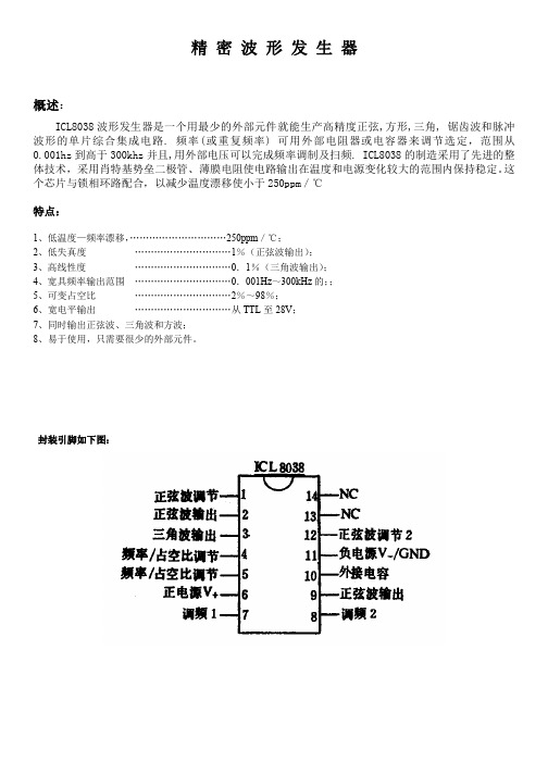
精密波形发生器概述:ICL8038波形发生器是一个用最少的外部元件就能生产高精度正弦,方形,三角,锯齿波和脉冲波形的单片综合集成电路.频率(或重复频率)可用外部电阻器或电容器来调节选定,范围从0.001hz到高于300khz并且,用外部电压可以完成频率调制及扫频.ICL8038的制造采用了先进的整体技术,采用肖特基势垒二极管、薄膜电阻使电路输出在温度和电源变化较大的范围内保持稳定。
这个芯片与锁相环路配合,以减少温度漂移使小于250ppm/℃特点:1、低温度—频率漂移,…………………………250ppm/℃;2、低失真度…………………………1%(正弦波输出);3、高线性度…………………………0.1%(三角波输出);4、宽具频率输出范围…………………………0.001Hz~300kHz的;;5、可变占空比…………………………2%~98%;6、宽电平输出…………………………从TTL至28V;7、同时输出正弦波、三角波和方波;8、易于使用,只需要很少的外部元件。
封装引脚如下图:ICL8038内部原理框图最大限值范围:供电电压(V-to V+) (36V)到V+输入电压(任何管脚) (V)–输入电流(管4-5).......................................25mA输出槽电流(管脚3和9)..................................25mA工作条件温度范围ICL8038AC,ICL8038BC,ICL8038CC............0℃to70℃图1:测试电路图2ICL8038内部详细的示意图应用信息(看功能图)由两个恒流源对外接电容C进行充电和放电,恒流源2的工作状态由触发器控制,同时恒流源1始终打开。
假设,触发器使得恒流源2关闭电容C由恒流源1充电,电容器C两端电压随时间线性上升。
当这个电压达到比较器1的输入电平(设定在2/3电源电压),触发器翻转改变状态,使恒流源2处于关闭状态。
常用电子制作IC型号、功能介绍全集

74HC573D 存储集成电路
IX0388CE 中频放大集成电路
SAA5290ZP 微处理集成电路
74HCT157 多路转换双输入集成电路 IX0411CEN1 微处理集成电路
SAA5297 微处理集成电路
74HCT4046A 压控振荡集成电路
IX0412CE 字符发生集成电路
微处理集成电路
74HC245 总线收发集成电路
理集成电路
SAA5261 电视信号处理集成电路
74HC32 或门四 2 输入集成电路
IX0365CE 伴音功率放大集成电路
SAA5281ZP 电视信号处理集成电路
74HC374 八 D 触发集成电路
IX0371GE 磁头控制集成电路
SAA5284 电视信号处理集成电路
87CK38N-3584 微处理集成电路
理集成电路
SAA9050 色度解码集成电路
87CK38N-3627 微处理集成电路
IX0603CE 视频、色度信号处理集成电路 SAA9051 色度解码集成电路
89C52 系统控制处理集成电路
IX0605CE 微处理集成电路
SAA9055 色度解码集成电路
89C55 系统控制处理集成电路
20810-F6096 存储集成电路
集成电路
路
2252B 微处理集成电路
IX0062CE 图像中频放大、视频放大集成电 S1D2503X01 视频信号处理 200MHz 集成
24C01ACEA 存储集成电路
路
电路
24C026 存储集成电路
IX0064CE 图像中频放大、检波、视频放大 S1D2512X01 偏转信号处理集成电路
74HC04 逻辑与非门集成电路
模块化仪器的广泛选择

√ 4-10
2
DAQ
3
PXI
4
模块仪器
5
GPIB及 总线扩展
6
PAC
7
运动控制
8
实时 分布式I/O
9
远程I/O
10
串行通信
型号 模拟输出 DAC分辨率 更新率 输出范围 输出阻抗 偏移范围
标准波形
任意波形存储 采样时钟调制
SYNC/Marker 10MHz基准频率输入 正弦输出 页码
PXI-7921 两线多路
切换器 24(两线) 48(单线)
DPDT(2路C类) 2 A@30 VDC
220VDC,125VAC 50VA,60W 2A
10μA@10mVDC 最大100mΩ 1024步 125次/秒 √ √ 4-19
PXI-7931 4组2x4 两线制矩阵模
块 32(两线) DPDT(2路C类) 2A@30 VDC 220VDC,125VAC 50 VA, 60 W
BNC, SMB 512 MB
±5 V, ±1 V 50 Ω, 1.5 MΩ
30 MHz
<-80 dB, DC to 1MHz BNC, SMB
512 MB, 128 MB
-
2通道(PXI-9820)
√
√
√
√
√
√
√
√
√I-9812(A)/PCI-9810 PCI
4通道 20 MS/s
PXI-9816/9826/9846
简介
凌华科技PXI/PCI-9816/9826/9846是4通道16位10MS/s,20MS/s,40MS/s采样数字化仪,专为输入信号频率高 达20MHz的高频和高动态范围的信号而设计。模拟输入范围可以通过编程设置为±1V/±0.2V或±5V/±0.4V。 配备了容量高达512MB的板载内存的PXI/PCI-9816/9826/9846,摆脱了PCI总线的约束,使之能储存更长时间 的波形。
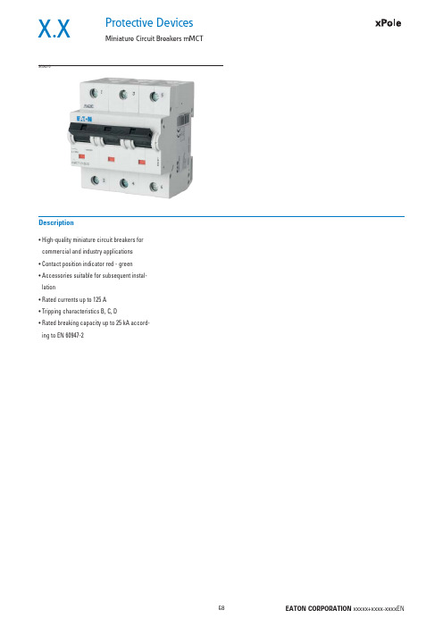
爱立智电路保护设备 Miniature 电路保护设备 mMCT EATON 商品说明书
Protective DevicesMiniature Circuit Breakers mMCTX.X• H igh-quality miniature circuit breakers for commercial and industry applications • C ontact position indicator red - green • A ccessories suitable for subsequent instal-lation• R ated currents up to 125 A • T ripping characteristics B, C, D• R ated breaking capacity up to 25 kA accord-ing to EN 60947-2DescriptionSG04210X.X Protective DevicesMiniature Circuit Breakers mMCTRated current I n (A)TypeDesignationArticle No.Units perpackage25 kA, Characteristic BSG0401020mMCT-B20/11525621225mMCT-B25/11526341232mMCT-B32/11525631240mMCT-B40/11525641250mMCT-B50/11525651263mMCT-B63/11526351280mMCT-B80/112964612100mMCT-B100/112964712125mMCT-B125/1129648121-poleSG0541020mMCT-B20/2152704625mMCT-B25/2152636632mMCT-B32/2152705640mMCT-B40/2152706650mMCT-B50/2152707663mMCT-B63/2152637680mMCT-B80/21296546100mMCT-B100/21296556125mMCT-B125/212965662-poleSG0421020mMCT-B20/3152716425mMCT-B25/3152638432mMCT-B32/3152717440mMCT-B40/3152718450mMCT-B50/3152719463mMCT-B63/3152639480mMCT-B80/31296624100mMCT-B100/31296634125mMCT-B125/312966443-poleSG0561020mMCT-B20/3N152740325mMCT-B25/3N153012332mMCT-B32/3N152741340mMCT-B40/3N152742350mMCT-B50/3N152743363mMCT-B63/3N153013380mMCT-B80/3N1296783100mMCT-B100/3N1296793125mMCT-B125/3N12968033+N-poleSG0551020mMCT-B20/4152728325mMCT-B25/4153010332mMCT-B32/4152729340mMCT-B40/4152730350mMCT-B50/4152731363mMCT-B63/4153011380mMCT-B80/412967034-poleProtective DevicesMiniature Circuit Breakers mMCT X.XRated current I n (A)TypeDesignationArticle No.Units perpackage25 kA, Characteristic CSG0401020mMCT-C20/11525661225mMCT-C25/11580591232mMCT-C32/11525671240mMCT-C40/11525681250mMCT-C50/11525691263mMCT-C63/11583101280mMCT-C80/112964912100mMCT-C100/112965012125mMCT-C125/1129651121-poleSG0541020mMCT-C20/2152708625mMCT-C25/2158313632mMCT-C32/2152709640mMCT-C40/2152710650mMCT-C50/2152711663mMCT-C63/2158314680mMCT-C80/21296576100mMCT-C100/21296586125mMCT-C125/212965962-poleSG0421020mMCT-C20/3152720425mMCT-C25/3158317432mMCT-C32/3152721440mMCT-C40/3152722450mMCT-C50/3152723463mMCT-C63/3158318480mMCT-C80/31296654100mMCT-C100/31296664125mMCT-C125/312966743-poleSG0561020mMCT-C20/3N152744325mMCT-C25/3N158325332mMCT-C32/3N152745340mMCT-C40/3N152746350mMCT-C50/3N152747363mMCT-C63/3N158326380mMCT-C80/3N1296813100mMCT-C100/3N1296823125mMCT-C125/3N12968333+N-poleSG0551020mMCT-C20/4152732325mMCT-C25/4158321332mMCT-C32/4152733340mMCT-C40/4152734350mMCT-C50/4152735363mMCT-C63/4158322380mMCT-C80/412967334-poleX.X Protective DevicesMiniature Circuit Breakers mMCTRated current I n (A)TypeDesignationArticle No.Units perpackage25 kA, Characteristic DSG0401020mMCT-D20/11527001225mMCT-D25/11583111232mMCT-D32/11527011240mMCT-D40/11527021250mMCT-D50/11527031263mMCT-D63/11583121280mMCT-D80/112965212100mMCT-D100/1129653121-poleSG0541020mMCT-D20/2152712625mMCT-D25/2158315632mMCT-D32/2152713640mMCT-D40/2152714650mMCT-D50/2152715663mMCT-D63/2158316680mMCT-D80/21296606100mMCT-D100/212966162-poleSG0421020mMCT-D20/3152724425mMCT-D25/3158319432mMCT-D32/3152725440mMCT-D40/3152726450mMCT-D50/3152727463mMCT-D63/3158320480mMCT-D80/31296684100mMCT-D100/312966943-poleSG0561020mMCT-D20/3N152748325mMCT-D25/3N158327332mMCT-D32/3N152749340mMCT-D40/3N152750350mMCT-D50/3N152751363mMCT-D63/3N158328380mMCT-D80/3N1296843100mMCT-D100/3N12968533+N-poleSG0551020mMCT-D20/4152736325mMCT-D25/4158323332mMCT-D32/4152737340mMCT-D40/4152738350mMCT-D50/4152739363mMCT-D63/4158324380mMCT-D80/412967634-poleX.XProtective DevicesMiniature Circuit Breakers mMCT - T echnical DataSpecifi cations | Miniature Circuit Breakers mMCTDescription• Independent switching contacts• W ith isolator function, meets the requirements of insulation co-ordination,distance between contacts ≥ 4 mm, for secure isolationAccessories:Auxiliary switch for subsequent installation (0.5 MU)Z-LHK248440Shunt trip release subsequent installation (1.5 MU)Z-LHASA/230248442Z-LHASA/24248441 Switching interlock LH-SPL285752Technical DatamMCTElectricalEN 60947-2Design according toCurrent test marks as printed onto the deviceRated voltage U n AC: 230/400 VDC: 60 V (per pole, max. 2 poles)Ultimate short circuit breaking capacity according to IEC/EN 60947-2Characteristic B, C I n = 20-63 A: 25 kAI n = 80-100 A: 20 kAI n = 125 A: 15 kACharacteristic D I n = 20-63 A: 25 kAI n = 80 A: 20 kAI n = 100 A: 15 kACharacteristic in accordance with B, C, DBack-up fuse max. 200 A gLRated insulation voltage U i440 VPeak withstand voltage U imp 4 kVSelectivity class in accordance with class 3Endurance≥ 20,000 switching operationsMechanicalFrame size45 mmDevice height90 mmDevice width27 mm (1.5MU) per poleMounting quick fastening with 2 lock-in positions on DIN rail IEC/EN 60715 Degree of protection IP20Degree of protection, built-in IP40Upper and lower terminals lift terminalsTerminal protection fi nger and hand touch safe, DGUV VS3, EN 50274Terminal capacity 2.5-50 mm2Connection diagrams4-pole1-pole 2-pole 3-pole 3+N-poleX.XProtective DevicesMiniature Circuit Breakers mMCT - T echnical DataDimensions (mm)Load CapacityDurchlassenergieMaximum let-through energy mMCT, Characteristic C, 1-poleMaximum let-through energy mMCT, Characteristic D, 1-poleLoad capacity in case of block installationEffect of ambient temperaturePermitted permanent load at ambient temperature T [°C] with n devices: I DL = I n K T (T)K N (N).Ambient temperature T [°C]L o a d c a p a c i t y K T [I /I n ]Number of devices (n) 1-poleL o a d c a p a c i t y f a c t o r KNL e t t h r o u g h e n e r g y I 2t [A 2 s e c ]Protective DevicesMiniature Circuit Breakers mMCT - T echnical DataX.XShort Circuit Selectivity mMCT towards D01, D02, D03 and NH size 00Selectivity towards back-up fuses D01, D02, D03••Selectivity towards back-up fuses NH size 00mMCT Rated current of the back-up fuse in A gL/gG I n [A]2535506380100Characteristic CCharacteristic D mMCT Rated current of the back-up fuse in A gL/gG I n [A]253540506380100125160200Characteristic CCharacteristic D mMCT Rated current of the back-up fuse in A gL/gG I n [A]2535506380100mMCT Rated current of the back-up fuse in A gL/gG I n [A]253540506380100125160200X.XProtective DevicesMiniature Circuit Breakers mMCT - T echnical DataShort Circuit Selectivity mMCT towards NZMIn case of short circuit, there is selectivity between the miniature circuit breakers mMCT and the upstream NZM up to the specifi ed values of the selectivity limit current I s [kA] (i. e. in case of short-circuit currents I ks under I s only the MCB will trip, in case of short circuit currents above this value both protective devices will respond). Overload and short-circuit release unit NZM at max. value.*) basically in accordance with EN 60898-1 D.5.2.bShort circuit selectivity Characteristic C towards NZM1*)Short circuit selectivity Characteristic D towards NZM1*)mMCT NZM...1-A gL/gG I n [A]40506380100125200.30.40.50.750.9 1.251) Selectivity limit current I sunder 0.5 kA2) S electivity limit current I s = rated breaking capacity I cn of the MCBDarker areas: no selectivitymMCT NZM...1-A gL/gG Short circuit selectivity Characteristic C towards NZM2*)Short circuit selectivity Characteristic D towards NZM2*)mMCTNZM...2-A gL/gG I n [A]40506380100125160200250200.30.40.50.750.9 1.25 1.8 2.5 3.5mMCT NZM...2-A gL/gG。
PLL IC SR1018B
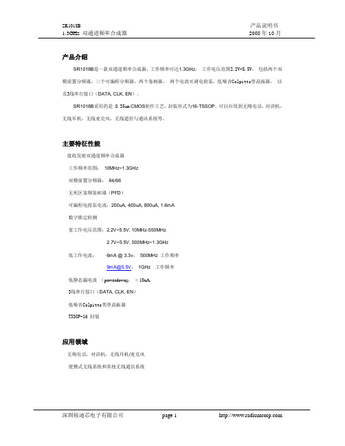
Prescaler 64/66
N Counter
N Counter
Prescaler 64/66
CP 2B
LD 6B
PFD
Control Circuit
PFD
CP
17B
2B
SW
R Counter
12B
XOSC
16 FIN2 15 VDD 14 CP2 13 GND 12 SW 11 OSCI 10 OSCO 9 BO
输出 -
输出 输入
输入 输入
输出 输出
输入
输入/输出 输出 输入
产品说明书 2008 年 10 月
引脚描述 通道1的前置分频器输入来自VCO的小 信号。 电源电压输入 (2.2V-5.5V)。 引脚2 和 引脚15在外部应该连起来。旁路电容应 该放的尽量靠近这些引脚,并且直接连 到地线。 通道1的电荷泵输出端口。连接到环路滤 波器,控制VCO的电压。 地线。引脚4 和引脚13在外部应该连起 来。 锁定检测输出。CMOS输出。 串行数据的时钟输入端。数据在时钟的 上升沿输入到串行接口的19位移位寄存 器中。 串行数据输入端。最低位首先输入,最 后两位是控制位。 装载使能输入端。当EN为高电平时,存 储在移位寄存器中的数据装载到4个锁 存器中的一个(由控制位决定)。 晶体振荡器频率的缓冲输出。是CMOS 输出。 内部振荡器的输出端口。如果参考频率 是由内部振荡器产生的,OSCO端连到晶 振。如果参考频率是由外部提供的, OSCO悬空 内部振荡器的输入端口,当参考频率是 由内部振荡器产生时,OSCI连到晶振。 外部时钟驱动时,连到时钟源。 开关转换端口,用来改变环路滤波器的 时间常数。漏端开路输出。 通道2的电荷泵输出端口。连接到环路滤 波器,控制VCO的电压。 通道2 的前置分频器输入来自VCO的小 信号。
PLL502-02HSC中文资料
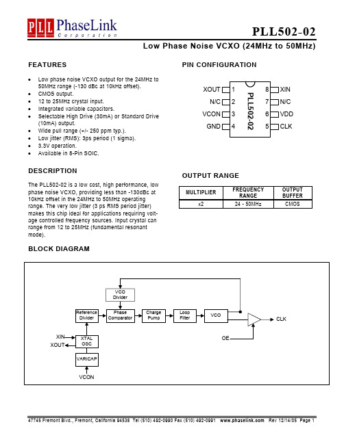
FEATURES• Low phase noise VCXO output for the 24MHz to50MHz range (-130 dBc at 10kHz offset). • CMOS output.• 12 to 25MHz crystal input. • Integrated variable capacitors.• Selectable High Drive (30mA) or Standard Drive(10mA) output.• Wide pull range (+/- 250 ppm typ.). • Low jitter (RMS): 3ps period (1 sigma). • 3.3V operation.• Available in 8-Pin SOIC.DESCRIPTIONThe PLL502-02 is a low cost, high performance, lowphase noise VCXO, providing less than -130dBc at 10kHz offset in the 24MHz to 50MHz operating range. The very low jitter (3 ps RMS period jitter) makes this chip ideal for applications requiring volt-age controlled frequency sources. Input crystal can range from 12 to 25MHz (fundamental resonant mode).PIN CONFIGURATIONOUTPUT RANGEMULTIPLIERFREQUENCY RANGE OUTPUT BUFFERx2 24 - 50MHz CMOSBLOCK DIAGRAMPLL502-0212345678XOUT N/C VCON GNDXIN VDD CLKN/CPIN DESCRIPTIONSName Number TypeDescriptionXOUT1ICrystal output. See Crystal Specifications on page 3.N/C 2,7 - Not connected. VCON 3 I Voltage Control input. GND 4 P Ground. CLK 5 O Output clock. VDD 6 P +3.3V power supply. XIN8ICrystal input. See Crystal Specifications on page 3.ELECTRICAL SPECIFICATIONS1. Absolute Maximum RatingsPARAMETERS SYMBOL MIN. MAX. UNITSSupply VoltageV DD 4.6 V Input Voltage, dc V I -0.5 V DD +0.5 V Output Voltage, dc V O -0.5 V DD +0.5 V Storage TemperatureT S -65 150 °C Ambient Operating Temperature* T A -40 85 °C Junction TemperatureT J 125 °C Lead Temperature (soldering, 10s) 260 °C ESD Protection, Human Body Model2 kVExposure of the device under conditions beyond the limits specified by Maximum Ratings for extended periods may cause permanent damage to thedevice and affect product reliability. These conditions represent a stress rating only, and functional operations of the device at these or any other conditions above the operational limits noted in this specification is not implied.* Note : Operating Temperature is guaranteed by design for all parts (COMMERCIAL and INDUSTRIAL), but tested for COMMERCIAL grade only.2. DC SpecificationsPARAMETERS SYMBOL CONDITIONS MIN. TYP. MAX. UNITSSupply Current, Dynamic, withLoaded Outputs I DD F XIN = 12 - 25MHzOutput load of 10pF16 20 mAOperating Voltage V DD 2.97 3.63 V I OH V OH = V DD -0.4V, V DD =3.3V 30 mA Output drive current (High Drive) I OL V OL = 0.4V, V DD = 3.3V30mAI OH V OH = V DD -0.4V, V DD =3.3V 10 mA Output drive current (Standard Drive) I OLV OL = 0.4V, V DD = 3.3V 10mAShort Circuit Current±50 mA VCXO Control VoltageVCON3.3V3. AC Electrical SpecificationsPARAMETERS SYMBOL CONDITIONS MIN.TYP.MAX.UNITS Input Crystal Frequency 12 25 MHz Output Clock Rise/Fall Time(Standard Drive)0.3V ~ 3.0V with 15 pF load 2.4Output Clock Rise/Fall Time (High Drive) 0.3V ~ 3.0V with 15 pF load 1.2nsOutput Clock Duty Cycle Measured @ 50% V DD 455055 % 4. Voltage Control Crystal OscillatorPARAMETERS SYMBOL CONDITIONS MIN.TYP.MAX.UNITS VCXO Stabilization Time * T VCXOSTB From power valid 10 msVCXO Tuning Range F XIN = 12 – 25MHz;XTAL C0/C1 < 2500V ≤ VCON ≤ 3.3V500 ppmCLK output pullability VCON=1.65V, ±1.65V ±200 ppmVCXO Tuning Characteristic 165ppm/V Pull range linearity 10% VCON pin input impedance 2000 kΩVCON modulation BW 0V ≤ VCON ≤ 3.3V, -3dB 25 kHzNote: Parameters denoted with an asterisk (*) represent nominal characterization data and are not production tested to any specific limits.5. Jitter and Phase Noise SpecificationPARAMETERS CONDITIONSMIN.TYP.MAX.UNITSRMS Period Jitter(1 sigma – 1000 samples) at 44MHz, with capacitive decoup-ling between VDD and GND.3 psPhase Noise relative to carrier 44MHz @100Hz offset -100 dBc/HzPhase Noise relative to carrier 44MHz @1kHz offset -123 dBc/HzPhase Noise relative to carrier 44MHz @10kHz offset -130 dBc/HzPhase Noise relative to carrier 44MHz @100kHz offset -125 dBc/HzPhase Noise relative to carrier 44MHz @1MHz offset -125 dBc/Hz6. Crystal SpecificationsPARAMETERS SYMBOLMIN.TYP.MAX.UNITSCrystal Resonator Frequency F XIN 12 25 MHzCrystal Loading Capacitance Rating C L (xtal)9.5 pFC0/C1250- ESR R S30 ΩNote: Crystal Loading rating: 9.5pF is the loading the crystal sees from the VCXO chip at VCON = 1.65V. It is assumed that the crystal will be atnominal frequency at this load. If the crystal requires more load to be at nominal frequency, the additional load must be added externally.This however may reduce the pull range.ORDERING INFORMATIONPhaseLink Corporation, reserves the right to make changes in its products or specifications, or both at any time without notice. The information fur-nished by Phaselink is believed to be accurate and reliable. However, PhaseLink makes no guarantee or warranty concerning the accuracy of said information and shall not be responsible for any loss or damage of whatever nature resulting from the use of, or reliance upon this product.LIFE SUPPORT POLICY: PhaseLink’s products are not authorized for use as critical components in life support devices or systems without the ex-press written approval of the President of PhaseLink Corporation.。
PD80F01x系列_中文资料_数据手册
Rev1.20
第1页
2020-7-27
Pdmicro Technology Ltd
PD80F01X
目录
特性..................................................................................................................................................................................1
2.1. 地址映射................................................................................................................................................................. 9 2.1.1. SFR,BANK0................................................................................................................................................. 9 2.1.2. SFR,BANK1............................................................................................................................................... 10 2.1.3. TMR0,地址 0x01........
PMAC801说明书

第 4 章 控制器功能配置 ..............................................................................................................................................11
目录
第 8 章 保护特性及参数整定 ......................................................................................................................................27
3.1 控制器主体外形尺寸 ..................................................................... 5 3.2 显示模块外形尺寸和安装示意图 ........................................................... 6 3.3 CT模块外形尺寸 ........................................................................ 7 3.4 扩展模块外形尺寸....................................................................... 8 3.5 电源模块外形尺寸....................................................................... 9 3.6 模块之间连接示意图 ..................................................................... 9
EM785840中文资料(ELAN Microelectronics)中文数据手册「EasyDatasheet - 矽搜」
• 两个8位计数器:C1与COUNTER2
• 内置看门狗定时器(WDT)
• 99.9%单指令周期命令
• 三种工作模式(主时钟可以从447.829k被编程为14.3MHz内部产生来自PLL)Mode
CPU状态
主时钟
32.768kHz时钟状态
睡眠模式
关掉
关掉
关掉
绿色模式
打开
关掉
打开
普通模式开启
打开
打开
· 输入端口中断功能
SEG1 SEG0 COM3 COM2 COM1 COM0 AVDD PLLC AVSS
P67 ADR/P66
44 1
43
42
41
40
39
38
37
36
35 3433
2
32
3
31
4
30
5
29
6
28
7
27
8
26
9
25
10
24
1112 13 14 15 16 17 18 19 20 21 2223
PC3 PC2/PWM2 PC1/PWM1 PC0 P70/INT0 P71/INT1 P72/INT2 P73/INT3 P74/SDI P75/SDO P76/SCK
__________________________________________________________________________________________________________________________________________________________________
用户应用笔记
(使用这种芯片之前,先看看下面描述说明,它包含重要信息.)
LP801中文资料
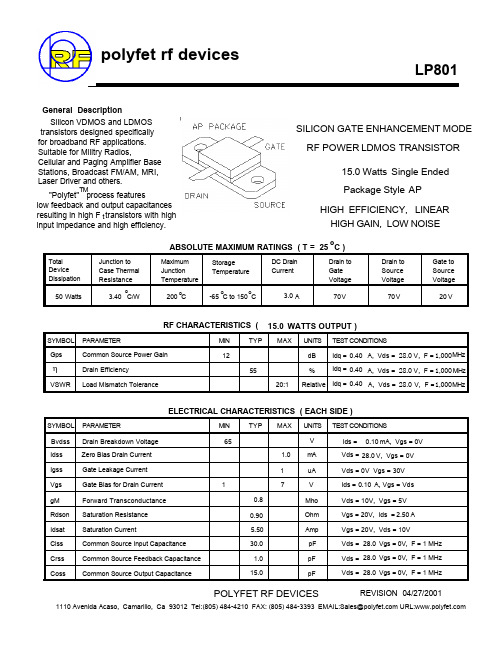
Total Device Dissipation 50 Watts Junction to Case Thermal Resistance o 3.40 C/W Maximum Junction Temperature o 200 C Storage Temperature o o -65 C to 150 C DC Drain Current Drain to Gate Voltage 70 V Drain to Source Voltage 70 V Gate to Source Voltage 20 V
L2B 1 DIE CAPACITANCE
16.00
100
14.00
10
Ciss Coss
12.00
1
Crss
Efficiency = 58%
10.00
8.00 3
GAIN
0
5
10
15
20
25
30
VDS IN VOLTS
PIN IN WATTS
IV CURVE
L2A 1 DICE IV
6
100
ID & GM VS VGS
元器件交易网H
LP801 POUT VS PIN F=1000 MHZ; IDQ=0.2A;VDS=28V
24 22 20 18 16 14 12 10 8 6 4 2 0 0.5 1 1.5 2 2.5
POUT 0.1
CAPACITANCE VS VOLTAGE
η
VSWR
Relative Idq = 0.40 A, Vds = 28.0 V, F = 1,000 MHz
ELECTRICAL CHARACTERISTICS ( EACH SIDE )
液晶电源管理芯片型号与封装代换型号

液晶电源管理芯片型号与封装代换型号液晶品牌与型号电源管理芯片型号与封装可代换型号xaslipyelBENQ 71G+1200AP40 直插1200AP10 1200AP60AOC 712SI EA1532A贴片xaslipyel三星940BW DM0565Rxaslipyel优派型号忘记 TOP245YNxaslipyelLG W1934S TOP246YNxaslipyel飞利浦170s6 dap02alsz 贴片xaslipyelLG型号忘记 LAF0001 可以用FAN7601代xaslipyel飞利浦170s6 dap02alsz=sg6841xaslipyelHP17驱动高压电源全一体 SG5841SZ贴片,可用SG6841DZ 代用。
xaslipyel联想后来出的像IBM的17的,SG6841DZ 可用SG6841D代用xaslipyel三星型号忘记 DM0465R(我记得还有这么一款的)xaslipyel飞利浦170c7 EA1532A贴片xaslipyel200D6、203D6、DAP8A 三种可以代用xaslipyel优派VA1703WB ld7552bps 贴片xaslipyel其他我知道的常用型号有xaslipyelSG6841DZ 贴片很多机器上用到xaslipyelSG5841SZ 贴片用SG6841DZ可以代用,xaslipyel美格WB9 LD7575PS清华同方 XP911W LD7575PS联想LXM -WL19AH LXM-WL19BH LD7575PS(早期有的用:NCP1203D6)联想LXM-17CH: 1203D6方正17寸:1203D6与LD7575PS方正19寸:LD7575PSBenQ: FP94VW FP73G FP71G+S FP71G+G FP71GX等都是用:1200AP40 LG 22(南京同创):LAF001与STR W6252 。
LG 19寸:LAF001 联想L193(福建-捷联代工):NCP1203D6PHILIPS 170S5 (FAN7601)还有LD7575可用203D6代用,只是1脚的对地电阻不同,LD7575是100K,203D6是24.1K,LP7552可用SG6841代用希望大家都列下来,这样子备PWM IC的时候就有个数了,知道买什么样子的电源管理芯片备用着,有时候手上没有,知道是电源管理坏了在那里干着急,反正PWM IC便宜的,可以每样备个2个,以备不时之需介绍几个LCD液晶显示器电源IC的代换希望能帮上大家.DAP8A\DAP7A\LD7575\203D6可以直接代换DAP02\SG5841\SG6841可以直接代换1200AP40\1200AP60\1203P60可以直接代换DM0465R\CM0565R\DM0565R可以直接代换TOP246Y\TOP247Y可以直接代换常见显示器IC代换OCP5001-----------TL5001AMC3100----------LTC3406/AT1366/MP2104 OCP2150----------- LTC3406/AT1366/MP2104 ACT6906----------- LTC3406/AT1366/MP2104 OCP2160-----------LTC3407 AMC34063A-----------AMC34063AMC7660------------AJC1564ACT4060--------------ZA3020LV/MP1410/MP9141ACT4065------------ZA3020/MP1580ACT4070----------ZA3030/MP1583/MP1591MP1593/MP1430 AMC2576-------LM2576AMC2596-------LM2596OCP2576--------LM2576OMC2596-------LM2596/AP1501VA7910---------MAX1674/75 L6920 AJC1610SM9621---------RJ9621/AJC1642PT1301----------RJ9266PT4101----------AJC1648/MP3202PT4102----------LT1937/AJC1896/AP1522/RJ9271/MP1540 ACT6311-------LT1937SP1937-----------LT1937/AJC1896/AP1522/RJ9271/MP1540 OCP3601---------MB3800OCP1451---------TL1451/BA9741/SP9741/AP200电源IC STR-G5643D G5653D G8653D 直接代换203D6和DAP8A 直接代换1200AP40和1200AP60直接代换5S0765和DP104、DP704直接代换DP804和DP904直接代换2S0680和2S0880直接代换TEA1507和TEA1533直接代换三星的DP104,704,804可以用5S0765代换,DP904不能用任何块代换行场振荡、场输出、视频ICTDA9109和SID2511、KB2511、STV7779直接代换TDA9103和STV7778直接代换TDA9112和TDA9113直接代换TDA9115和TDA9116、STV6888直接代换TDA9118和STV9118直接代换TDA8172和TDA9302、TDA8177直接代换TDA1675 和DBL2056直接代换TDA9210和STV9210直接代换LM1203和LM2203、DBL2054直接代换TDA9116用STV6888代换,TDA4856可以用TDA4841PS代换,TDA9112可以用TDA9113代换,S1D2511可以用TDA9109代换203D6200D6LD7575DAP8A203X6直接代换SG6841SG5841DAPO2直接代换DM0456 DM0565直接代换1200AP401200AP601203AP10直接代。
液晶常用电源管理芯片
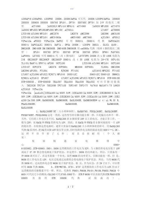
1200AP40 1200AP60、1203P60 200D6、203D6 DAP8A 可互代203D6/1203P6 DAP8A 2S0680 2S0880 3S0680 3S0880 5S0765 DP104、DP704 8S0765C DP704加24V的稳压二极管ACT4060 ZA3020LV/MP1410/MP9141 ACT4065 ZA3020/MP1580 ACT4070 ZA3030/MP1583/MP1591MP1593/MP1430 ACT6311 LT1937 ACT6906 LTC3406/AT1366/MP2104 AMC2576 LM2576 AMC2596 LM2596 AMC3100 LTC3406/AT1366/MP2104 AMC34063A AMC34063 AMC7660 AJC1564 AP8012 VIPer12A AP8022 VIPer22A DAP02 可用SG5841 /SG6841代换DAP02ALSZ SG6841 DAP02ALSZ SG6841 DAP7A、DP8A 203D6、1203P6 DH321、DL321 Q100、DM0265R DM0465R DM/CM0565R DM0465R/DM0565R 用cm0565r代换〔取掉4脚的稳压二极管〕DP104 5S0765 DP704 5S0765 DP706 5S0765 DP804 DP904 FAN7601 LAF0001 LD7552 可用SG6841代〔改4脚电阻〕LD7575PS 203D6改1脚100K电阻为24K OB2268CP OB2269CP OB2268CP SG6841改4脚100K电阻为20-47K OCP1451 TL1451/BA9741/SP9741/AP200 OCP2150 LTC3406/AT1366/MP2104 OCP2160 LTC3407 OCP2576 LM2576 OCP3601 MB3800 OCP5001 TL5001 OMC2596 LM2596/AP1501 PT1301 RJ9266 PT4101 AJC1648/MP3202 PT4102 LT1937/AJC1896/AP1522/RJ9271/MP1540 SG5841SZ SG6841DZ/SG6841D SM9621 RJ9621/AJC1642 SP1937 LT1937/AJC1896/AP1522/RJ9271/MP1540 STR-G5643D STR-G5653D、STR-G8653D TEA1507 TEA1533 TEA1530 TEA1532对应引脚功能接入THX202H TFC719 THX203H TFC718S TOP246Y TOP247Y VA7910 MAX1674/75 L6920 AJC1610 VIPer12AVIPer22A [audio01]ICE2A165(1A/650V.31W);ICE2A265(2A/650V.52W);ICE2B0565(0.5A/6 50V.23W):ICE2B165(1A/650V.31W);ICE2B265(2A/650V.52W);ICE2A180(1A/800V.29W);ICE2 A280(2A/800.50W).KA5H0365R, KA5M0365R, KA5L0365R, KA5M0365RN# u) t! u1 W1 B) R, PKA5L0365RN, KA5H0380R, KA5M0380R, KA5L0380R1、KA5Q1265RF/RT〔大小两种体积〕、KA5Q0765、FSCQ1265RT、KACQ1265RF、FSCQ0765RT、FSCQ1565Q这是一类的,这些型号的引脚功能全都一样,只是输出功率不一样。
常用锁相环芯片
常用锁相环芯片一、引言锁相环(PLL)是一种常见的电路,用于将输入信号的频率和相位与参考信号同步。
锁相环芯片是实现锁相环功能的重要部件,广泛应用于通信、计算机、音频等领域。
本文将介绍常用的锁相环芯片。
二、基本概念1. 锁相环(PLL)锁相环是一种反馈控制系统,它可以将输入信号和参考信号的频率和相位同步。
锁相环由比较器、低通滤波器、振荡器和分频器等组成。
2. 锁定时间指从开始输入参考信号到输出信号与参考信号同步所需的时间。
3. 抖动指输出信号与参考信号之间的瞬时差异。
抖动越小,表示输出信号与参考信号同步更稳定。
三、常用锁相环芯片1. CD4046CD4046是一款经典的数字锁相环芯片,由德州仪器公司推出。
它具有简单易用、性能稳定等特点,广泛应用于通讯、音频等领域。
2. AD9901AD9901是ADI公司推出的高性能数字锁相环芯片,具有高精度、低抖动等特点,广泛应用于通讯、雷达等领域。
3. LM565LM565是美国国家半导体公司推出的模拟锁相环芯片,具有锁定时间短、抖动小等特点,广泛应用于通讯、音频等领域。
4. MAX038MAX038是美国MAXIM公司推出的高性能模拟锁相环芯片,具有高精度、低抖动等特点,广泛应用于音频、视频等领域。
四、常见问题及解决方法1. 锁定时间过长可能是由于参考信号和输入信号的频率差异过大导致。
可以通过增加分频器的分频比例或调整低通滤波器的截止频率来解决。
2. 抖动过大可能是由于反馈控制系统不稳定或噪声干扰导致。
可以通过增加低通滤波器的阻尼系数或减小比较器灵敏度来解决。
3. 输出信号失真可能是由于振荡器质量差或分频器性能不佳导致。
可以尝试更换振荡器或分频器来解决。
五、总结锁相环芯片是实现锁相环功能的重要组成部件,常用的锁相环芯片有CD4046、AD9901、LM565和MAX038等。
在使用锁相环芯片时,需要注意锁定时间、抖动和输出信号失真等问题,并采取相应的解决方法。
P800Flash 量产型 Flash 编程器产品用户手册说明书

广州致远电子有限公司P800Flash量产型Flash 编程器修订历史目录1. P800Flash编程器简介 (1)2. eMMC烧录方案信息表 (2)3. eMMC烧录功能介绍 (3)3.1创建 (3)3.1.1新建工程 (3)3.1.2芯片选择 (4)3.1.3烧录方式 (4)3.2配置 (5)3.2.1芯片选择 (6)3.2.2通道配置 (6)3.2.3组合配置 (7)3.2.4芯片配置 (7)3.2.5操作选项 (8)3.3保存 (9)3.4操作 (9)4. eMMC烧录操作流程 (11)4.1方式一、文件调入 (11)4.1.1创建工程 (11)4.1.2选择芯片 (12)4.1.3烧录模式 (12)4.1.4时钟频率 (13)4.1.5调入文件 (13)4.1.6ExtCSD寄存器配置 (15)4.1.7通道配置 (16)4.1.8保存工程 (17)4.2方式二、文件分析 (18)4.2.1创建工程 (18)4.2.2选择芯片 (19)4.2.3烧录模式 (19)4.2.4时钟频率 (20)4.2.5分析文件 (20)4.2.6ExtCSD寄存器配置 (23)4.2.7通道配置 (24)4.2.8保存工程 (25)4.3方式三、母片分析 (26)4.3.1创建工程 (26)4.3.2选择芯片 (27)4.3.3烧录模式 (27)4.3.4时钟频率 (28)4.3.5分析母片 (29)4.3.6通道配置 (31)4.3.7保存工程 (32)4.4方式四、母片拷贝 (32)4.4.1创建工程 (33)4.4.2选择芯片 (34)4.4.3烧录模式 (34)4.4.4时钟频率 (35)4.4.5分析母片 (35)4.4.6通道配置 (38)4.4.7保存工程 (38)5. eMMC芯片烧录 (40)5.1量产烧录 (40)5.2芯片测试 (40)5.3日志文件 (41)5.3.1即时信息 (41)5.3.2Log文件 (41)6.免责声明 (43)1. P800Flash编程器简介P800Flash是广州致远电子有限公司历经十多年的编程技术积累,深耕打造的一款脱机、座烧、量产型的Flash编程器;它能支持各种封装的EEPROM Flash、SPI NorFlash、Parallel NorFlash、NandFlash、SPI NandFlash、eMMC等存储器。
MAX5841中文资料
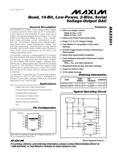
o Rail-to-Rail Output Buffer Amplifiers
o Three Software-Selectable Power-Down Output Impedances 100kΩ, 1kΩ, and High Impedance
ELECTRICAL CHARACTERISTICS
(VDD = +2.7V to +5.5V, GND = 0, VREF = VDD, RL = 5kΩ, CL = 200pF, TA = TMIN to TMAX, unless otherwise noted. Typical values are at VDD = +5V, TA = +25°C.) (Note 1)
元器件交易网
19-1777; Rev 0; 1/02
MAX5841
Quad, 10-Bit, Low-Power, 2-Wire, Serial Voltage-Output DAC
General Description
The MAX5841 is a quad, 10-bit voltage output, digitalto-analog converter (DAC) with an I2C™-compatible, 2-wire interface that operates at clock rates up to 400kHz. The device operates from a single 2.7V to 5.5V supply and draws only 230µA at VDD = 3.6V. A powerdown mode decreases current consumption to less than 1µA. The MAX5841 features three software-selectable power-down output impedances: 100kΩ, 1kΩ, and high impedance. Other features include internal precision Rail-to-Rail® output buffers and a power-on reset (POR) circuit that powers up the DAC in the 100kΩ power-down mode. The MAX5841 features a double-buffered I2C-compatible serial interface that allows multiple devices to share a single bus. All logic inputs are CMOS-logic compatible and buffered with Schmitt triggers, allowing direct interfacing to optocoupled and transformer-isolated interfaces. The MAX5841 minimizes digital noise feedthrough by disconnecting the clock (SCL) signal from the rest of the device when an address mismatch is detected.
QL801-单芯片电子密码锁
If you think our products can be used with your products, We welcome you to participate in cooperation.We can offer to you our technical information.We very much look forward to doing business with you.1、概述QL801电子密码锁功能芯片是泉州强联电子科技有限公司针对市场需求而设计开发的一款专用的密码锁芯片。
QL801单个芯片集成了密码的输入识别、修改、断电的自动保存、对象的控制、撤防、布防控制多种功能,不用再外接其他任何的芯片,为您的产品提供了一个可靠、简单、低成本的应用方案。
同市面常见的电子密码锁具有的功能相比较,QL801可以提供更加稳定可靠的性能,更低的价格,更方便的使用,同时还可以减小实际的体积。
2、应用场合1、电子密码门锁(家庭、企业、公司、酒店)2、电子密码保险柜3、电子密码箱4、电子防盗密匙5、其他重要设备的开启6、等等3、特点1、单个芯片实现:密码的输入识别、修改;密码断电的自动保存;对象的控制;撤防、布防控制;彻底解决旧式电子密码锁还要外挂存储器、容易掉码的缺陷。
2、高可靠性:密码可由1-20位数字任意组合,密码量多达几千万亿组以上,而且如果连续输入3次的错误密码,密码锁将封闭键盘1分钟(这个时间可以根据实际的需要定制),达到无法猜测和破解。
3、可以采用电池供电或直流电源供电,功耗低。
(有两种电压范围的功能芯片供用户选择:3.6-5.5V宽电压芯片QL801,2.0-3.8V低电压芯片QL801LE)4、有四个输出控制端口:(具体功能也可根据实际的需要定制)输出1:上电为高电平,当输入一次正确的密码后翻转电平输出2:上电为低电平,当输入一次正确的密码后翻转电平输出3:上电为高电平,当输入一次正确的密码后输出一个0.5秒的低电平脉冲信号。
- 1、下载文档前请自行甄别文档内容的完整性,平台不提供额外的编辑、内容补充、找答案等附加服务。
- 2、"仅部分预览"的文档,不可在线预览部分如存在完整性等问题,可反馈申请退款(可完整预览的文档不适用该条件!)。
- 3、如文档侵犯您的权益,请联系客服反馈,我们会尽快为您处理(人工客服工作时间:9:00-18:30)。
X
kHz
X
mSec
dBm
X
dBc/Hz
dBc/Hz
dBc/Hz X
Volts
mA
X
dBc
X
dBc
dBc
X
dBc
X
MHz Vp-p dBc/Hz
k
Package Information PLL400
Package Type:
) (0.6 x 0.6 x 0.14 inches
Drawing Number: 60080
Comments X Indicates parameter to be tested 100% in production
Remarks
Performance tests and ratings for Sirenza Microdevices' products were performed internally by Sirenza and measured using specific computer systems and/or components and reflect the approximate performance of the the products as measured by those tests. Any difference in circuit implementation, test software, or test equipment may affect actual performance. The information provided herein is believed to be reliable at press time and Sirenza Microdevices assumes no responsibility for the use of this information. All such use shall be entirely at the user's own risk. Prices and specifications for Sirenza Microdevices' products are subject to change without notice. Buyers should consult Sirenza Microdevices' standard terms and conditions of sale for Sirenza's limited warranty with regard to its products. These products may be patented or include patented technology. No patent rights or licenses to any of the circuits described herein are implied or granted to any third party. Sirenza Microdevices does not authorize or warrant any product for use in life-support devices and/or systems.
Output Impedance -
Min 5800
-6 2.85
0.4
Typ 5840 200
1 -3
-54 -78 -105
3 35 -70 -70
-12 -30
10
-145 100 50
Max 5880
4 0
-48 -70 -95 3.15 40 -60 -60
-8 -20
2
Units
X
MHz
元器件交易网
PLL Product Specification
Model:
PLL801-5840(Y)
Customer:
SIRENZA MICRODEVICES, INC.
Rev:
Date: 9/1/2006
AppNote: 112, Opt. 100
Operating Temperature Range: ( -35 ° to 85 ° C)
RoHS Compliant
To order models as RoHS Compliant add "Y" suffix to base model number.
Parameter Frequency Range Step Size Settling Time - To within 1.0 kHz Output Power Output Phase Noise:
Page 1 of 1
Sirenza Microdevices, Inc.
303 S. Technology Ct.
Broomfield, CO 80021
tel 303.327.3030 fax 303.410.7988
