5040EX103J3中文资料
装载机配件目录解析

山 东 临 工常用 配 套 表 车 型 泵 型车 型LG 916 ( 918 ) 临工CBGjA2050 左矩 LG 950-1 (ZL50G) LG918-1 临工CBGj2050/1010-XF 左矩 ZL 30F临工CBGjA2040 左矩 临工CBGjA2080 左矩 LG 950-2 (ZL 50G-1) LG 930 临工CBGjA2032 左矩标准CBGj2080 左矩 (老) LG 952临工CBGj3100A 左矩(新) LG 930-1(ZL30G ) 临工CBGjA2040 左矩 临工CBGjA2080B 左矩LG 933临工CBGjA2032 左矩LG952H 临工CBGj3100A 左矩 临工DF25.2C-16LG 953(L)LG 936隔油CBGj2063/2040 左矩临工CBGj2063A 左矩 (新)临工CBGj3100A 左矩临工JHP3160左矩 (2009.11~今) LG936(高配) 隔油CBGj2063/2040 左矩(老)临工DF32.2C-18临工CBGj2063A 左矩 (新)LG 956临工CBGj2080左矩 临工CBGj3100/1010-XF 左矩隔油CBGj2063/2040 左矩 LG938 临工CBGj2063 左矩临工CBGj3100A 左矩临工CBGj3100/1010C-XF 右渐 LG956(高配) 临工CBGj2080/1010G-XF 左矩 ZL 40F 标准CBG2080 左矩 临工JHP2100/2025 左矩 临工CBGj3125 左矩 临工CBGj3100A 左矩 LG946 临工JHP3125 左矩 LG956L 临工JHP2100/Gj0010 左矩 ZL 50F标准CBG2080 左矩 临工JHP3160 左矩临工CBGj3160 左矩 LG958 临工CBGj2080/1010C-XF 右渐 LG 950临工CBGjA2080左矩临工CBGj3100C 左渐 临工CBGj2080B 左矩LG958 (高配) 临工CBGj3100A 左矩临工JHP3160C 右渐 LG968 临工JHP3100/02010-XF 右渐 临工JHP3100C 右渐 两头忙 临工CBGjA2063 左 WZ30-25临工 JHP2063/Gj1010 左平 临工 CBGj0025/0010 左平临工LG953装载机变速泵,行走泵立方装载机配件有限公司主营:(变速泵,行走泵)厦工、龙工、柳工、山推等品牌原装进口装载机配件;装载机的主要部件包括:1. 发动机配件2. 变矩器上有三个泵,工作泵(供应举升,翻斗压力油)转向泵(供应转向压力油)变速泵也称行走泵(供 应变矩器,变速箱压力油),有些机型转向泵上还装有先导泵(供应操纵阀先导压力油)(变速泵,行走泵)3..工作液压油路,液压油箱,工作泵,多路阀,举升油缸和翻斗油缸4. 行走油路:变速箱油底壳油,行走泵,一路进变矩器一路进档位阀,变速箱离合器5. 驱动:传动轴,主差速器,轮边减速器(变速泵,行走泵)6. 转向油路:油箱,转向泵,稳流阀(或者优先阀)转向器,转向油缸7. 变速箱有一体的(行星式)和分体的(定轴式)两种(变速泵,行走泵)临工LG953装载机变速泵,行走泵•变矩器、变速箱系统•刹车、制动系统•驱动桥及轮边•装载机油品•工作装置系统•传动轴总成及配件•车架系统•驾驶室及配件•覆盖件系统•电器及仪表系统•工作液压、转向系统•发动机系统•发动机用滤清器总成、滤..•冷却、散热系统•操纵系统•变矩器、变速箱滤清器、..•液压、转向系统滤清器、..•全车垫、密封件等•制动系统及其他配件•散热器•泵、阀类•未分类•查看所有分类>主要从事厦工装载机配件.临工装载机配件.蒙凌装载机配件.山工装载机配件.龙泰装载机配件.德工装载机配件.龙工装载机配件.柳工装载机配件等装载机配件,上柴6135发动机配件,上柴D6114发动机配件,玉柴6108发动机配件,一拖洛阳6105发动机配件,无锡6110发动机配件,潍柴WD615斯太尔发动机配件,潍柴6105发动机配件,道依茨6105发动机配件,各种操纵软轴,换档软轴,换档器总成,熄火拉线,刹车片,制动活塞,油缸油封,杭齿变速箱配件,山推315变矩器配件,变速箱密封件,组合垫,铲斗,斗齿,主刀板,轴承,关节轴承,滚针,空气加力泵,各种板式冷却器,机油冷却器,水箱总成,变速箱冷却器,空压机,水泵总成,17.5-25轮胎,20.5-25轮胎,23.5-25轮胎,空气滤芯,机油滤芯,柴油滤芯,液压箱滤芯,变矩器变速箱滤芯滤网支架,轮胎保护链防滑链,销轴套,装载机螺栓,二轴总成,泵轮,涡轮组,导轮座,弹性板,变速箱壳体,变矩器壳体,变矩器中节,主传动总成,差速器,角盆齿,轮边减速器,半轴,传动轴,十字轴,万向节,变速泵,变速阀,多路阀,工作泵,转向泵,全液压转向器,半液压方向机,恒流阀,卸荷阀,流量放大阀,优先阀,单稳阀,各种发动机水管,耐油胶管,柴油管,钢丝水管等的批发.零售.配件齐全,价格合理,技术力量雄厚专业配套徐工装载机,山工装载机,临工装载机,常林装载机,柳工装载机,龙工装载机,成工装载机,厦工装载机,郑工装载机我公司专业配套徐工吊车,柳工吊车,浦沅吊车,泰安东岳吊车,中联重科等吊车厂家专业配套三一重装、佳木斯煤机、煤科总院太原分院,凯盛重工、上海创力、上海普昱、上海天地、辽源煤机、石家庄煤机、石家庄中煤、北方交通、西安煤机、南京晨光、沈阳北方重工、包头北方重工、鞍山强力等煤矿掘进机厂家公司始终坚持\\"质量至上,诚信共赢\\"的经营宗旨,秉承向用户提供高品质,高可靠性的产品和及时有效的服务承诺.单,双联,三联,四联泵等可替代进口的高压齿轮油泵,且比同类进口产品价格更低,质量更可靠,并拥有完善售后服务体系。
派克机电产品纵览说明书

■ᅠ高技术应用的控制器■ᅠ基于工业以太网的运动控制系统■ᅠ集成多轴运动控制器■ᅠ智能伺服驱动器■ᅠ工业以太网多轴伺服驱动器■ᅠ通用伺服驱动器■ᅠ智能直流调速器■ᅠ通用直流调速器派克机电产品纵览运动控制驱动技术直流调速器■ᅠ智能交流变频器■ᅠ通用交流变频器交流变频器2■ᅠ滚珠丝杠驱动工作台■ᅠ直线电机驱动工作台■ᅠ高精度微型工作台■ᅠ经济型■ᅠ高精度高精度执行器与工作台行星齿轮减速机■ᅠ伺服电机■ᅠ防爆伺服电机■ᅠ高速大功率伺服电机■ᅠ高性能车载电机■ᅠ直线电机组件■ᅠ直驱电机■ᅠ高性能伺服电机■ᅠ电动缸■ᅠ线性执行器电机执行器3ACR 系列是派克主要的独立封装的运动控制器,能够实现多达八轴的运动控制。
简单易用的项目开发组件,使应用系统构建及维护快速,高效。
ACR74C/78C 是4轴/8轴运动控制器;ACR74T 是集成4轴步进电机驱动器的驱控一体机;ACR74V/78V 是集成4轴/8轴低压伺服驱动器的驱控一体机。
强大、集成化和为机械市场设计的派克自动化运动控制器(PAC)为OEM 提供了基于标准的自动化解决方案,能够满足严苛的应用要求。
PAC 将先进逻辑、多轴运动、信号处理和网络发布的可视化整合到一个以性能为导向的解决方案中,进而消除不必要的硬件和通信链接,并提高开发者的效率。
PAC网络架构派克自动化运动控制器 - PACACR 控制器系列•ᅠ K eywords: PAC CPU 运算能力更强•ᅠP AC: EtherCAT, 多轴插补•ᅠA CR:模拟量模式,简单易用ACR7C/7V ACR7000PAC3404智能伺服驱动器 - Compax3Compax3是派克汉尼汾不同国家和地区推出的伺服驱动器产品。
驱动器系列包括单轴,多轴驱动器,还有液压控制器。
这一系列驱动的功率从1到110kVA。
这一伺服驱动器的整个研发及制造过程全部在德国完成。
另外的生产基地也在美国建成。
作为一款销往不同国家和地区的伺服驱动控制器,Compax3在世界各地都有销售。
长城汽车赛铃、赛酷系列零部件手册说明书
每天进步一点点
PDF 文件使用 "pdfFactory" 试用版本创建 肀ww肀
3. This manual provides the components (maintenance fittings)code of the surface color of the internal
series parts and components (maintenance fittings) with updated, modificated and added new content.
The Usage of this manual:
1. Provide most of the SAILOR、SOCOOL users with references, when users need to know item code, name, quantity and
前言
本着精简、高效、实用、统一、参考的原则,在较短的时间内完成了《长城汽车赛铃、赛酷系列零部件手册(维 修配件)》第三版。它是在第二版《长城汽车赛铃、赛酷系列零部件手册(维修配件)》基础上更新、改进、补充部分内容后编制 而成的最新版本。
这本手册的用途是: 1 . 可供广大赛铃、赛酷皮卡汽车用户了解赛铃、赛酷系列轻型货车各种车型的零部件代号、名称、用量、适用车型、 零部件之间的装配关系及其结构组成时参考。 2 . 可供广大用户、维修站(点)选择和购买赛铃、赛酷系列轻型货车各车型的零部件和维修配件时参考。 3 . 可供企业内部、长城售后服务公司、配件部及市场服务工作的相关人员为用户和维修站(点)进行售后服务工作时 参考。
This manual is edited according to the technologic information of SAILOR、SOCOOL automobiles produced by our company now. With the increasingly development of technology, the structure of the SAILOR、SOCOOL automobiles will be
X5040立式铣床资料
2011年金蓝领技师专业论文X5040型升降台铣床采用微电子型多功能继电器控制线路*名:***职业:维修电工鉴定等级:技师单位:山东煤机集团泰安煤矿机械有限公司二零一一年九月二是十五日摘要本文阐述了x5040型升降台铣床采用微电子型多功能继电器控制线路的工作原理及机床的操作步骤。
关键词:微电子型多功能继电器X5040升降台铣床电力拖动故障保护前言在机械行业中,几乎所有的工作机械都用电动机来拖动,这种方式成为电力拖动。
它和用内燃机等来拖动相比,具有效率高、价格低、操作简单和维修方便等优点。
应用电力拖动还能对工作机械实行远距离操纵和自动控制,在实现生产过程自动化方面日益显示出它的优越性。
X5040立式升降台铣床是一种强力金属切削的机床,该机床适于加工各种零件的平面、斜面、沟槽、孔等,是机械制造、模具、仪器、仪表、汽车、摩托车等行业的理想加工设备。
X5040型升降台铣床电源进线为三相四线制380V,50HZ 动力电路。
电气控制部分除机床照明与电源指示线路外主要采用微电子型多功能继电器控制,型号为WJ1-20/10,它的特点是接线简单,可靠性高,动作相应快,通过程序控制机床的动作,并且维修简单,操作方便。
机床的操作主要集中在滑鞍前侧按钮站及右壁。
目录摘要 (2)前言 (3)一、X5040型升降台铣床的主要结构 (5)1、床身部分 (5)2、主传动部分 (5)3、主轴变速操纵部分 (6)4、进给变速箱部分 (7)5、工作台部分 (7)二、X5040铣床的电力拖动工作原理及操作步骤 (8)1、WJ1-20/10微电子型多功能继电器的简介 (8)2、电源部分 (8)3、交流电机控制 (9)4、主轴运动的电气操作 (9)5、进给运动的操作 (10)6、快速运动的操作 (10)7、冷却泵与机床照明电路 (10)8、机床故障保护 (10)三、附图 (11)1、机床外观图 (11)2、机床电路图 (11)结论 (12)参考文献 (12)一、X5040升降台铣床的主要结构1、床身部分由床身和底座组成,底座内腔是冷却液箱。
Kraftform Kompakt 系列产品说明书

KRAFTFORM KOMPAKT 50KRAFTFORMKOMPAKT 61KRAFTFORMKOMPAKT 90KRAFTFORMKOMPAKT 30KRAFTFORMKOMPAKT 91With the Kraftform Kompakt ®series, the user is fully equipped for both kinds of screwdriving with only one set of tools.The Kraftform Kompakt ®series offers tools:The new generation of service tools:Kraftform Kompakt ®.Compact tools for both manual and power screwdriving.Kraftform Kompakt ®50!Compact boxes -- small enough Kraftform Kompakt ®- for bothmanual and machine operation.Thus, Kraftform Kompakt ®50 is the right tool for all users who place the greatest emphasis on versatility.81With ten different Kraftform Kompakt ®sets the user is well equipped for almost any application in trade and industry.KraftformKompakt ®40, 41, 60, 61, 62a For both manual and machine operation.a Engineered to the highest quality for professional use,a packaged in unique, space-saving format.The magnetic bit adaptor (for power tool use) quickly turns into a full screwdriver when combined with the ergonomic Kraftform ®handle.KraftformKompakt ®70 and 71KraftformKompakt ®90 and 91A big-diameter Kraftform ®han-dle, a power tool adaptor with quick-release chuck formachine use and 30 bits pro-vide the user with all the tools he needs.Quick fastening and easy direc-tion reversal with only one hand: no problem with the Kraftform Kompakt ®Handy-Ratchet.Technicians who have to deal with screw-driving a lot would-n't miss these tool sets. They are the best tools for the job.Pouches with bitholding screw-driver and 89 mm long bits.82056657 1 bit holder 815/4/1 Kraftform 1with quick-release chuck1 Universal bit holder 895/4/1Bits:3 bits each 855/1TH PZ 1/25; PZ 2/25; PZ 3/25Code Content:Kraftform Kompakt ® 3211 pieces setKraftform Kompakt ®1010 pieces set056653 1 bit holder 813/1 Kraftform 1with quick-release chuck Bits:1 bit each 867/1TZ TX 10; TX 15; TX 201 bit each 855/1TZ PZ 1/25; PZ 2/251 bit each 851/1TZ PH 1/25; PH 2/251 bit each 800/1TZ 0,5 x 4,0; 1,0 x 5,5Code Content:KraftformKompakt ® 3111 pieces set0566581 bit holder 815/4/1 Kraftform1with quick-release chuck1 Universal bit holder 895/4/1Bits:1 bit each 867/1 Z TX 10; TX 15; TX 20;TX 25; TX 30; TX 401 bit each 855/1TH PZ 1/25; PZ 2/25; PZ 3/25CodeContent:Kraftform Kompakt ®1110 pieces set056652 1 bit holder 813/1 Kraftform 1with quick-release chuck Bits:1 bit each 867/1TZ TX 5; TX 6; TX 7; TX 8; TX 9; TX 10 1 bit 851/1Z PH 01 bit 851/1TZ PH 1/251 bit 800/1TZ 0,5 x 3,0Code Content:Kraftform Kompakt ®Mobility and flexibility in service and maintenance.056654 1 bit holder 815/4/1 Kraftform 1with quick-release chuck1 Universal bit holder 895/4/1Bits:1 bit each 855/1TZ PZ 1/25; PZ 2/25; PZ 3/251 bit each 851/1TZ PH 1/25; PH 2/25; PH 3/251 bit each 800/1TZ 0,6 x 4,5; 1,0 x 5,5; 1,2 x 6,5Code Content:Kraftform Kompakt ® 3011 pieces set83Kraftform Kompakt ® 5014 pieces set056656 1 bayonet bit holder 817/4/1 Kraftform11 bayonet holder 897/4/1 with quick-release chuck Bits:1 bit each 867/1Z BO TX 10; TX 15; TX 20;TX 25; TX 30; TX 401 bit each 855/1Z PZ 1/25; PZ 2/251 bit each 851/1Z PH 1/25; PH 2/251 bit each 800/1Z 0,6 x 4,5; 1,0 x 5,5Code Content:Kraftform Kompakt ® 50 Imperial14 pieces set135951 1 bayonet bit holder 817/4/1 Kraftform11 bayonet holder 897/4/1 with quick-release chuck Bits:1 bit each 867/1Z BO TX 10; TX 15; TX 20;TX 25; TX 30; TX 401 bit each 868/1Z # 1; #21 bit each 851/1Z PH 1/25; PH 2/251 bit each 800/1Z 0,6 x 4,5; 1,0 x 5,5Code Content:Kraftform Kompakt ® 70 Allround32 pieces set0571101 Kraftformbitholding screwdriver 816/4/111 Universal bit holder 895/4/1K Bits:3 bits each 851/1 TZ PH 1/25; PH 2/25; PH 3/253 bits each 855/1 TZ PZ 1/25; PZ 2/25; PZ 3/251 bit each 867/1 Z BO TX 10; TX 15; TX 20; TX 25;TX 30; TX 401 bit each 840/1 Z SW 4; SW 5; SW 61 bit each 800/1 TZ 0,6 x 4,5; 1,0 x 5,5; 1,2 x 6,5Code Content:Kraftform Kompakt ® 71 Security32 pieces set0571111 Kraftformbitholding screwdriver 816/4/111 Universal bit holder 895/4/1KBits:1 bit each 840/1Z BOSW2; SW2,5; SW3;SW4; SW5; SW61 bit each 857/1Z # 4; # 6; # 8; # 101 bit each 867/1Z BO TX 7; TX 8; TX 9;TX 10; TX 15; TX 20; TX 25; TX 30; TX 401 bit each 871/1Z # 6; # 8; # 10; #1/4"1 bit each 875/1Z # 1; # 2; # 31 bit each 868/1Z # 0; # 1; # 2; # 3Code Content:84Kraftform Kompakt ® 9022 pieces set0569481/4" Handy-Ratchet 98/4/11with quick-release chuck1 Universal bit holder 895/4/1K Bits:1 bit each 867/1Z TX 10; TX 15; TX 20; TX 25;TX 30; TX 402 bits 855/1Z PZ 1/253 bits PZ 2/251 bit PZ 3/251 bit each 851/1Z PH 1/25; PH 2/25; 3/251 bit each 800/1Z 1,0 x 5,5; 1,2 x 6,51 bit each 840/1Z SW 3; SW 4; SW 5CodeContent:KraftformKompakt®9118 pieces set0569471/4" Handy-Ratchet 98/4/11with quick-release chuck1 Universal bit holder 895/4/1K 1 adaptor 870/1Bits:1 bit each 867/1Z BO TX 15; TX 20; TX 25; TX 301 bit each 851/1Z PH 1/25; PH 2/25; PH 3/251 bit each 840/1Z SW 3; SW 4; SW 5Hexagon Sockets:1 each 790 HA SW 5,5; SW 7; SW 8;SW 10; SW 13Code Content:Kraftform Kompakt ®Light, compact and versatile.Kraftform Kompakt ® 90 Imperial22 pieces set135954/4" Handy-Ratchet 98/4/11with quick-release chuck1 Universal bit holder 895/4/1 K Bits:1 bit each 867/1Z TX 10; TX 15; TX 20; TX 25;TX 30; TX 402 bits 851/1Z PH 1/253 bits PH 2/251 bit PH 3/251 bit each 800/1Z 1,0 x 5,5; 1,2 x 6,51 bit each 868/1Z # 1; # 2; # 31 bit each 840/1 Z 3/32"; 1/8"; 5/32"Code Content:Kraftform Kompakt ®91 Imperial18 pieces set135953/4" Handy-Ratchet 98/4/11with quick-release chuck1 Universal bit holder 895/4/1 K 1 adaptor 870/1Bits:1 bit each 867/1Z BO TX 15; TX 20; TX 25; TX 301 bit each 851/1Z PH 1/25; PH 2/25; PH 3/251 bit each 840/1Z3/32"; 1/8"; 5/32"Hexagon Sockets:1 each790 HA3/16"; 1/4"; 5/16"; 3/8"; 1/2"Code Content:85059298 1 Kraftform bitholding screwdriver 816/4/11Bits (89 mm long):1 bit each 855/4Z PZ 1; PZ 21 bit each 851/4Z PH 1; PH 21 bit each 800/4Z 1,0 x 5,5; 1,2 x 6,5Code Content:059299 1 Kraftformbitholding screwdriver 816/4/11Bits (89 mm long):1 bit each 867/4Z BO TX 15; TX 20; TX 25; TX 301 bit each 855/4Z PZ 1; PZ 2; PZ 31 bit each851/4Z PH 1; PH 2; PH 3Code Content:Kraftform Kompakt ® 40 pouch with 89 mm long bits7 pieces setKraftform Kompakt ® 41 pouch with 89 mm long bits11 pieces set86059295 1 Kraftformbitholding screwdriver 816/4/11Bits (89 mm long):1 bit each 851/4 Z PH 1;PH 2; PH 31 bit each 855/4 Z PZ 1; PZ 2; PZ 31 bit each 867/4 Z BO TX 10; TX 15; TX 20; TX 25; TX 301 bit 800/4 Z 1,0 x 5,51 bit each 840/4 Z SW 3; SW 4; SW 5; SW 6CodeContent:Kraftform Kompakt ® 60 pouch with 89 mm long bits17 pieces set059296 1 Kraftform bitholding screwdriver 816/4/11Bits (89 mm long):1 bit each 867/4 Z BO TX 10; TX 15; TX 20; TX 25; TX 301 bit each 871/4 Z #6; #8; #101 bit each 875/4 Z #1; #2; #3; #41 bit each 857/4 Z #4; #6; #8; #10Code Content:Kraftform Kompakt ® 61 pouch with 89 mm long bits17 pieces set059297 1 Kraftformbitholding screwdriver 816/4/11Bits (89 mm long):1 bit each 851/4 Z PH 1;PH ; PH 31 bit each 855/4 Z PZ 1; PZ 2; PZ 31 bit eacht 867/4 Z BO TX 8; TX 10; TX 15; TX 20;TX 25; TX 27; TX 30; TX 401 bit each 840/4 Z BO SW 2: SW 2,5; SW 3; SW 4;SW 5; SW 61 bit each 800/4 Z 1,2 x 6,51 bit each 871/4 Z #6; #8; #101 bit each 875/4 Z #1; #2; #3; #41 bit each 857/4 Z #4; #6; #8; #10Code Content:Kraftform Kompakt ® 62 pouch with 89 mm long bits33 pieces setKraftform Kompakt ®Light, compact and versatile.87Application:For 1/4"-hexagon insert bits, DIN 3126-C 6,3Drive: 1/4"-hexagon with quick-release bitholderHandle:Kraftform ®with anti-roll protection, three components813/1 Quick-Release Bitholding Screwdriver0512711/4"D 6,3905CodeDIN inch 3126mm Application:For 1/4"-hexagon insert bits, DIN 3126-C + E 6,3Drive: 1/4"-hexagon with quick-release bitholderHandle:Kraftform ®with anti-roll protection, three components815/4/1 Quick-Release Bitholding Screwdriver,magnetic0514701/4"D 6,31035F 6,3CodeDIN inch 3126mm Application:For 1/4"-hexagon insert bits, DIN 3126-C + E 6,3Drive: 1/4"-hexagon with quick-release bitholderHandle:Kraftform ®with anti-roll protection, three components816/4/1 Quick-Release Bitholding Screwdriver,magnetic0514601/4"D 6,31175F 6,3CodeDIN inch 3126mm Drive:1/4"-hexagonDIN 3126-D 6,3, with quick-release chuckHandle:Kraftform ®with elasto-mer soft zones, needle bearing supported free turning ratchet,integrated switch for forward or reverse operation.98/4/1 Kraftform ®Handy-Ratchet0032631/4"140100 5 9/16"4"1Code A B A B mm mm inch inch Application:For 1/4"-hexagon insert bits, DIN 3126-C + E 6,3Drive: Bayonett Holder: 1/4"-hexa-gon with quick-release bitholderHandle:Kraftform ®with anti-roll protection, three components817/4/1 Bitholding Screwdriver with Bayonett Holder0514801/4" D 6,31024 3/4"2F 6,3CodeDIN A inch 3126mm inch Application:For 1/4"-hexagon insert bits, DIN 3126-C + E 6,3Drive: 1/4" DIN 3126-E 6,3Output: 1/4"-hexagon with quick-release bitholder897/4/1 Bayonet Holder0539701/4" D 6,361024"2F 6,3Code DINAinch 3126mmmm inchKRAFTFORM KOMPAKT 31KRAFTFORM KOMPAKT 50KRAFTFORMKOMPAKT 61KRAFTFORMKOMPAKT 90KRAFTFORMKOMPAKT 30KRAFTFORMKOMPAKT 91。
卡尔玛机车配件手册查询方法

发动机
TWD 731VE,DSI 9 TWD 730VE
TWD 731 VE/ ME,DI 9 TWD 720 VE
Cummins QSB 6.7
September 25, 2020
1
S11eptember 25, 2020
正面吊常用变速箱型号
正面吊型号
DC 4160 DRD 420- 450
DRF 400 - 450
通过以上介绍,你了解了零件的查询方法了吗?
1、找出机车型号、序列号 2、确定出生纸 3、根据出生纸找出主手册
。或根据序列号找出随 车的配件手册 4、确定零件的组别 5、在相应的组别根据零件的 相关信息确定零件的编号
查阅步骤指导说明
下面我们就开始实际零件的查询练习吧 !
根据零件信息,和根据零件分类 有两种不同的零件查询方法以确 定零件的编号和位置。 可参考:A、单个零件
Meritor(Rockwell) PRC7534W4H
DRD420-60S5 DC4160RS5
Rockwell PRC7534W4H
S14eptember 25, 2020
堆高机驱动桥
堆高机型号
DCE 70 DCE 80 DCE90 DCT90
驱动桥型号
Kessler D81PL478LB5340 Kessler D91PL488 NLB
6、零件号,在订购零配件的时候区别其他零件的编号。 7、用瑞典语及英语表述的部件(组件)标题 8、注解、说明
September 25, 2020
28
从配件手册文本页面下部可以知道:
9、部门号:内部登记标准
13、
10、插图号:指示文字页面的插图
例如:920936.0171 主目录
AS5040中文版
CSn 接逻辑高电平时,可将数据输出引脚(DO)置 为三态,并终止串行数据传输。脚也用于对准模式 (见第 19 页)以及编程模式(见 14 页)
引脚 12 允许采用单根连线输出 10 位绝对位置值。 此数值被编码成脉宽调制信号,脉宽的步长为 1μs( 一整圈为 1μs 至 1024μs)。通过使用外部低通滤波 器,数字 PWM 信号可以转换成模拟电压,从而可以 直接取代电位器。
约为1kHz的脉宽调制信号;模式 3.x下为LSB
13 NC
-
必须保持开路
14 NC
-
必须保持开路
15 VDD3V3
S
3V 调节器输出(参见图 19)
16 VDD5V
S
5V 正电源电压
表 2:SSOP16 的引脚说明
DO_OD DO DI_PD DI_PU
数字输出,漏极开路 数字输出 数字输入,带下拉 数字输入,带上拉
3.3.2 CMOS / 编程输入:Prog (工作条件:Tamb = -40 至+125°C, VDD5V = 3.0-3.6V (3V 工作) VDD5V = 4.5-5.5V (5V 工作),除非另有规定)
参数 高电平输入电压 高电平输入电压 低电平输入电压 下拉高电平输入电流
符号 VIH VPROG VIL IiL
4
B_Dir_V
DO
模式2.x:旋转方向
模式3.x:V信号(相位2)
5
NC
-
必须保持开路
模式1.x和模式2.x :Index信号指
6
Index_ W
DO
XK5040数控立式铣床结构设计说明书
哈尔滨工业大学华德应用技术学院本科生毕业设计(论文)摘要数控机床即数字程序控制机床,是一种自动化机床,数控技术是数控机床研究的核心,是制造业实现自动化、网络化、柔性化、集成化的基础。
随着制造技术的发展,现代数控机床借助现代设计技术、工序集约化和新的功能部件使机床的加工范围、动态性能、加工精度和可靠性有了极大的提高。
本文主要对XK5040数控立式铣床及控制系统进行设计,首先分析立式铣床的加工特点和加工要求确定其主参数,包括运动和动力参数;根据主参数和设计要求进行主运动系统、进给系统设计。
主要进行主运动系统和进给系统的机械结构设计及滚珠丝杠和步进电机的选型和校核。
关键词数控技术;立式铣床;结构设计I哈尔滨工业大学华德应用技术学院本科生毕业设计(论文)AbstractThe numerical control engine bed is the digital process control engine bed, is one kind of automated engine bed, the numerical control technology is the core which the numerical control engine bed studies, is the manufacturing industry realization automation, the network, the flexibility, the integrated foundation. Along with the manufacture technology development, the modern numerical control engine bed with the aid of the modern design technology, the working procedure intensification and the new function part caused the engine bed the processing scope, the dynamic performance, the processing precision and the reliability had the enormous enhancement .This article mainly carries on the design to the XK5040 numerical control vertical milling machine , first analyzes the vertical milling machine the processing characteristic and the processing request determines its host parameter, including movement and dynamic parameter; Carry on the host kinematic scheme according to the host parameter and the design request, enters for the system and the control system hardware circuit design. Mainly carries on the host kinematic scheme and enters for the system mechanism design and the ball bearing guide screw and electric stepping motor shaping and the examination;Key words Numerical control technology; Vertical milling machine; DesignII哈尔滨工业大学华德应用技术学院本科生毕业设计(论文)目录摘要 (I)Abstract ....................................................... I I 第1章总体设计............................................ - 1 -1.1铣床简介.............................................. - 1 -1.2 XK5040型数控铣床的总体布局主要技术参数及总传动系统图.- 1 -1.2.1 XK5040型数控铣床的总体布局..................... - 1 -1.2.2 XK5040型数控铣床的主要技术参数................. - 3 -1.2.3 总传动系统图................................... - 4 - 第2章主运动系统设计...................................... - 6 -2.1 传动系统设计......................................... - 6 -2.1.1参数的拟定....................................... - 6 -2.1.2 传动结构或结构网的选择.......................... - 6 -2.1.3 转速图拟定...................................... - 7 -2.1.4齿轮齿数的确定及传动系统图的绘制................ - 10 -2.2传动件的估算与验算................................... - 14 -2.2.1传动轴的估算和验算.............................. - 14 -2.2.2齿轮模数的估算.................................. - 17 -2.3 展开图设计.......................................... - 22 -2.3.1结构实际的内容及技术要求........................ - 22 -2.3.2齿轮块的设计.................................... - 24 -2.3.3传动轴设计...................................... - 26 -2.3.4主轴组件设计.................................... - 29 -2.4制动器设计........................................... - 35 -2.4.1按扭矩选择...................................... - 35 -2.5截面图设计........................................... - 37 -2.5.1轴的空间布置.................................... - 37 -2.5.2操纵机构........................................ - 38 -2.5.3润滑............................................ - 38 -2.5.4箱体设计的确有关问题............................ - 39 - 第3章进给系统设计........................................ - 40 -3.1总体方案设计......................................... - 40 -3.1.1对进给伺服系统的基本要求........................ - 40 -3.1.2进给伺服系统的设计要求.......................... - 40 -3.1.3总体方案........................................ - 40 -3.2进给伺服系统机械部分设计............................. - 41 -3.2.1确定脉冲当量计算切削力.......................... - 41 -III哈尔滨工业大学华德应用技术学院本科生毕业设计(论文)3.2.2滚珠丝杆螺母副的计算和造型...................... - 43 -3.2.3齿轮传动比计算.................................. - 53 -3.2.4步进电机的计算和选型............................ - 54 -3.2.5进给伺服系统机械部分结构设计.................... - 65 - 结论....................................................... - 69 - 致谢....................................................... - 69 - 参考文献................................................... - 69 - 附录1. (72)附录2...................................................... - 74 -IV哈尔滨工业大学华德应用技术学院本科生毕业设计(论文)第1章总体设计1.1铣床简介铣床是一种用途广泛的机床。
庆铃汽车产品型号介绍
庆铃汽车产品型号、规格介绍⒈产品系列:庆铃汽车公司现生产的产品有两大类(商用车和乘用车),四个系列(N系列、F 系列、TF系列、UC系列)。
①商用车商用车主要包含:·N系列的各车型:NHR55ELACJ、NKR55GLEWACJ、NKR55LLEACJAX、NKR77GLEACJA、NKR77LLEWCJA、NKR77PLLACJA、等等。
·F系列的各车型:如FVR34J、FVZ34N、FVM34Q、CXA34T、QL1250SRFZ 等等。
·TF系列的各车型:如TFR17HDLMD、TFS17HDLM、TFR55HDLJD、TFS55HDLJB等等。
②乘用车乘用车主要包含UC系列的各车型。
如:QL6470DY11、QL6470D11;QL649011、QL6490Y11;QL6470DJ、QL6470DYJ;QL6470DY611等等。
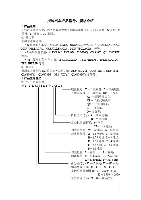
⒉产品型号含义:①N、F系列车型例1底盘代号:Y-二类底盘;S-三类底盘专用车代号:X-厢式车;GC-工程车;XS-代探头厢式车;XB-半厢式厢式车;QX-工程抢险车;ZH-指挥车;D-自御车;A-铁木货箱;B-全铁货箱发动机排放配置:J-增压;CJ-中冷增压;驾驶室型式:W-双排座;A-单排座;载质量代号:A-1.5吨级;E-2吨级;B-1.75吨级;L-3.吨级;D-1.25吨级;N-4吨级;F-2.2吨级;G-2.5吨级;P-4.5吨级;驾驶位置:L-左侧;R-右侧;轴距代号:E-2490mm;G-2765 mm;L-3360 mm;P-3815 mm;55-4J系列;77-4K系列;驱动型式代号:R-4×2;S-4×4车辆总质量范围kg:H-2800~3700;K-3500~5900车型类别代号:N-平头载货汽车例X-厢式货车J-4500mm;34-6HK1、6HK1-TC;R-4×2; M-6×2;Z-6×4;:V-15~21.5X-21.5~25F、C-F系列重型货车;G-F系列重型牵引车例3系列轻型货车-2006年前)底盘代号:Y-二类底盘;S-三类底盘;驱动型式代号:R-4×2; S-4×4;驾驶室型式代号:A-单排座;W-双排座;轴距代号:E-2490mm;G-2765 mm;L-3360 mm;P-3815 mm;J-4500mm;T-6400mm;发动机代号:B-6HK1;H-4KH1-TC;J-4JB1-TC;G-6HK1-TC;S-6UZ1-TC;T -4HK1-TC专用车分类代号:X-厢式汽车;产品序号:0-基本车型;1-笫一次变动:04-4吨;10-10吨; 25-25吨;1-载货汽车;3-越野汽车;5-专用汽车;6-客车例4系列轻型客车-2006年前)后桥型式:D-后单轮;发动机排放配置:J-增压;CJ-中冷增压;发动机代号:55-4J系列;77-4K系列;产品序号:0-基本车型;1-笫一次变动主参数代号(车辆修约总长度):54-5.2~5.8m59-5.8~6.0m车辆类别代号:客车②TF系列车型例专用车代号:GC-工程车;QX-抢险车;ZH-指挥车;X-厢式车;XL-连体厢式车载质量kg:A-500;B-800;D-450;发动机排放配置:M-电喷;J-增压;驾驶位置代号:L-左侧;R-右侧驾驶室型式代号:D-双排座;S-单排座;轴距代号:H-3025mm发动机代号:17-4ZE1-MPI电喷汽油机;55-4JB1-T1增压柴油机;驱动型式代号:R-4×2; S-4×4;设计最大载质量kg:F-1000车型类别代号:轻型载货汽车③UC例1年前)专用车代号:QX-工程抢险车;ZH-指挥车;GC-工程车;企业自定代号:11-电喷、手动档;12-电喷、自动档;J-增压企业自定代号:6-6VD1发动机(4缸机不标注);驱动型式代号:Y-4×4;企业自定代号:D-多用途产品序号:0-基本车型;1-笫一次变动主参数代号(车辆修约总长度):车辆类别代号:客车企业代号:QL-庆铃汽车股份有限公司。
东成电子零部件数据表单说明书
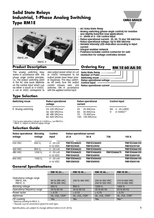
Rated operational Blocking Control Rated operational current voltage voltage input 25A 50A 75A 100A230VAC 650V p 4-20mA RM1E23AA25RM1E23AA50RM1E23AA1000-10VDC RM1E23V25RM1E23V50RM1E23V100400VAC 850V p 4-20mA RM1E40AA25RM1E40AA50RM1E40AA100480VAC 1200V p 4-20mA RM1E48AA25RM1E48AA50RM1E48AA75RM1E48AA1000-10VDC RM1E48V25RM1E48V50RM1E48V100600VAC1400V p4-20mA RM1E60AA25RM1E60AA50RM1E60AA1000-10VDCRM1E60V25RM1E60V50RM1E60V100Switching mode Rated operational Rated operational Control input voltagecurrent E:Analog switching23:230VACrms*25:25AACrms AA:4-20mADC 40:400VACrms 50:50AACrms V:0-10VDC**48:480VACrms 75:75AACrms 60:600VACrms100:100AACrms*For nominal operational voltage of 110VACrms,use RM1E23...**RM1E..V ..require an external supply voltage•AC Solid State Relay•Analog switching (phase-angle control)for resistive and slightly inductive load applications •4-20mA or 0-10V control input•Rated operational current:25,50,75and 100AACrms •Rated operational voltage:Up to 600VACrms•Variable intensity LED-indication according to input current•Integral snubber network•Polarized lockable control connector for safe connection for voltage controlled versionProduct DescriptionThe analog switching relay works in accordance with the phase angle control principle,i.e.,the output switching point in the AC sine wave depends on the control input which can be either 4-20mA or 0-10VDC.4mA or 0VDC correspond tozero output power whilst 20mA or 10VDC correspond to full output power (near linear pow-er response).The relay switch-es off every time the output current crosses zero,and switches ON in accordance with the applied control input.Solid State RelaysType SelectionSelection GuideGeneral Specifications**Heatsink must be connected to ground for 600V typesIndustrial,1-Phase Analog Switching Type RM1ERM1E..AARM1E..VInput SpecificationsNote:The use of twisted pair cable for the control input is recommendedOutput SpecificationsHousing SpecificationsFunctional DiagramHeatsink Dimensions(load current versus ambient temperature)With the output fully ON (360°conduction angle)RM1E..25T AAmbient temp.[°C]25.022.520.017.515.012.510.07.55.02.5Powerdissipation [W]Thermal resistance [K/W]Loadcurrent [A]3.23 2.80 2.37 1.94 1.51 1.09233.70 3.21 2.73 2.24 1.75 1.26214.30 3.74 3.17 2.61 2.05 1.49185.07 4.41 3.76 3.10 2.44 1.78156.12 5.33 4.54 3.75 2.96 2.17137.58 6.61 5.64 4.66 3.69 2.72109.808.557.306.054.80 3.55813.511.8010.098.37 6.664.946-18.315.713.0410.397.744-----72203040506070RM1E..50T AAmbient temp.[°C]50.045.040.035.030.025.020.015.010.05.0Powerdissipation [W]Thermal resistance [K/W]Loadcurrent [A]1.25 1.070.880.700.520.34551.46 1.25 1.040.840.630.42481.73 1.49 1.25 1.010.770.52412.08 1.80 1.51 1.230.940.66352.56 2.22 1.87 1.53 1.180.84293.24 2.81 2.38 1.95 1.52 1.09234.26 3.71 3.15 2.59 2.03 1.47185.99 5.22 4.45 3.67 2.90 2.12139.498.277.06 5.85 4.64 3.438-17.515.012.49.917.394203040506070Thermal SpecificationsIsolationRM1.60..500.990.810.630.440.260.081.28 1.070.860.650.440.231.64 1.40 1.150.910.670.422.11 1.82 1.54 1.250.960.672.60 2.25 1.90 1.55 1.200.853.30 2.86 2.43 1.99 1.55 1.114.36 3.79 3.22 2.65 2.08 1.516.1 5.4 4.6 3.77 2.97 2.189.768.527.36.04.83.54----15.4712.8510.247.650.045.040.035.030.025.020.015.010.05.0Loadcurrent [A]Thermal resistance [K/W]T AAmbient temp.[°C]Powerdissipation [W]554841352923181384203040506070RM1E (75)1.000.880.750.630.500.381.15 1.000.860.720.570.431.33 1.16 1.000.830.660.501.56 1.37 1.170.980.780.591.88 1.65 1.41 1.180.940.712.33 2.04 1.75 1.46 1.170.873.01 2.64 2.26 1.88 1.51 1.134.16 3.64 3.12 2.60 2.08 1.566.465.664.854.043.23 2.4213.4211.7410.068.39 6.71 5.0375.067.560.052.545.037.530.022.515.07.5Loadcurrent [A]Thermal resistance [K/W]T AAmbient temp.[°C]Powerdissipation [W]8070605143342719126203040506070DimensionsHeatsink Dimensions(load current versus ambient temperature)-Cont ...RM1E..100T A100.090.080.070.060.050.040.030.020.010.00.600.520.430.340.260.171170.740.640.540.440.340.241010.910.790.680.560.450.33871.090.960.820.680.550.41731.33 1.16 1.000.830.660.50601.66 1.45 1.24 1.040.830.62482.16 1.89 1.62 1.35 1.080.81373.01 2.64 2.26 1.88 1.51 1.13274.73 4.14 3.55 2.96 2.37 1.78179.948.707.45 6.21 4.97 3.738203040506070Belastnings-strøm [A]Termisk modstand [K/W]Omgivende temp.[°C]Effekttab [W]ApplicationsThis relay is suitable for control of heaters,lighting and slightly inductive loads such as small fans.The relay can also be used for soft turn-on of high-power incandescent lamps.Transfer CharacteristicsOutput power as a function of control inputControl current (mA)Control voltage (VDC)Output power4008 2.52512550167.5752010994to 20U line(Black)0V (Blue)0-10VDC (Brown)+24VDCU lineRM1E..V ..----5.00K/W 3.00K/W 2.70K/W 2.00K/W 1.35K/W 1.25K/W 1.20K/W 1.10K/W 0.80K/W 0.45K/W 0.40K/W 0.25K/W <0.25K/W ----K/WCarlo Gavazzi Heatsink (see Accessories)No heatsink required RHS 300RHS 100RHS 45C RHS 45B RHS 90ARHS 45C plus fan RHS 45Bplus fan RHS 112A RHS 301RHS 90A plus fan RHS 112A plus fan RHS 301plus fanConsult your distributor Infinite heatsink -No solutionHeatsink SelectionThermal resistance...Note:For power dissipation values smaller than those shown above,please refer to the corresponding heatsink curve in the SSR Accessories Section is referred to.N/A >0W >25W >55W >60W >60W >0W >0W >100W >80W >0W >0W >0WN/A N/A..for power dissipation Cable 3-wireCable 1Ribbon Cable SelectionRCS 3-100-1。
5040基于SAE_J1939_的CAN通讯规范

概述 .............................................................................................................................................................. 3 发送报文汇总列表 ............................................................................................................................................... 3 接收报文汇总列表 ............................................................................................................................................... 4 6.2 CAN 发送报文 (TX – 车辆应用层)........................................................................................................... 5 CAN 发送报文 (续表 1) ..................................................................................................................................... 6 CAN 发送报文 (续表 2) ..................................................................................................................................... 7 CAN 发送报文 (续表 3) ..................................................................................................................................... 8 CAN 发送报文 (续表 4) ..................................................................................................................................... 9 CAN 发送报文 (续表 5) ................................................................................................................................... 10 CAN 发送报文 (续表 6) ................................................................................................................................... 11 CAN 发送报文 (续表 7) ................................................................................................................................... 12 CAN 发送报文 (续表 8) ................................................................................................................................... 13 CAN 发送报文 (续表 9) ................................................................................................................................... 14 CAN 发送报文 续表 10) ................................................................................................................................ 15 6.3 CAN 接收报文 (RX – 车辆应用层) ................................................................................................... 16 CAN 接收报文(续表 1) ................................................................................................................................ 17 CAN 接收报文(续表 2) ................................................................................................................................ 18 CAN 接收报文(续表 3) ................................................................................................................................ 19 CAN 接收报文(续表 4) ................................................................................................................................ 20 CAN 接收报文(续表 5) ................................................................................................................................ 21 CAN 接收报文(续表 6) ................................................................................................................................ 22 CAN 接收报文(续表 7) ................................................................................................................................ 23 CAN 接收报文(续表 8) ................................................................................................................................ 24
1032E资料

Eight GLBs, 16 I/O cells, two dedicated inputs and one
E ORP are connected together to make a Megablock (see S Figure 1). The outputs of the eight GLBs are connected U to a set of 16 universal I/O cells by the ORP. Each ispLSI
— Reprogram Soldered Devices for Faster Prototyping
N • OFFERS THE EASE OF USE AND FAST SYSTEM
SPEED OF PLDs WITH THE DENSITY AND FLEXIBILITY
R OF FIELD PROGRAMMABLE GATE ARRAYS
— Complete Programmable Device Can Combine Glue
O Logic and Structured Designs F — Enhanced Pin Locking Capability
— Four Dedicated Clock Input Pins — Synchronous and Asynchronous Clocks
compatible voltages and the output drivers can source 4
L mA or sink 8 mA. Each output can be programmed p independently for fast or slow output slew rate to miniis mize overall output switching noise.
Rockwell Automation E300电子过载保护设备说明书
E300 Electronic Overload RelayBulletin Numbers 193, 592Selection GuideOverviewBulletin 193/592-E300 OverviewThe E300 Electronic Overload Relay is the newest technology for overload protection. Its modular design, communication options, diagnostic information, simplified wiring, and integration into Logix technology make this the ideal overload for motor control applications in an automation system.E300 Electronic Overload Relays provide the following benefits:•Intelligent motor control (EtherNet/IP enabled)• Scalable solution• Diagnostic Information• Integrated I/O• Adjustable trip class 5 (30)• Wide current range• Test/Reset button• Programmable trip and warning settings• True RMS current/voltage sensing (50/60 Hz)• Protection for single- and three-phase motorsNOTE: Y our order must include 1) the Cat. No. of the sensing module, control module, and communication module selected, and 2)if required, Cat. No. of any accessories.Standards Compliance and CertificationsStandards Compliance CertificationsUL508UL ListedUL1053 (Class I and Class II)CE MarkedUL 60947-1CSA CertifiedUL 60947-4-1CCCEN 60947-1KCCEN 60947-4-1CSA22.2, No. 14CSA22.2, No. 60947-1CSA22.2, No. 60947-4-1GB 14048.4Product OverviewThe E300 relay consists of three modules: sensing, control and communications. You have choices in each of the three with additional accessories to tailor the electronic overload for your application’s exact needs.OverviewSensing ModuleSensing Options• Voltage/current/ground fault • Current/ground fault • Current Current Range [A]• 0.5...30• 6...60•10...100•20 (200)Control ModuleCommunication Module•EtherNet/IPExpansion Digital I/OYou can add up to four additional expansion digital modules to the E300 relay expansion bus. • 4 inputs/2 relay outputs •24V DC •120V AC •240V ACExpansion Analog I/OYou can add up to four additional expansion analog modules to the E300 relay expansion bus. • 3 universal analog inputs/1 analog output •0…10V •0…5V •1…5V •0…20 mA •4…20 mA•RTD (2-wire or 3-wire)•0…150 Ω•0…750 Ω•0…3000 Ω•0…6000 Ω (PTC/NTC)Control Voltage I/OI/O and Protection (1)(1)Includes PTC thermistor and external ground fault.Inputs Relay OutputsInputs Relay Outputs110…120V AC, 50/60 Hz 4322220…240V AC, 50/60 Hz432224V DC6342Product SelectionControl ModulesCommunication ModulesExpansion ModulesVoltage/Current/Ground FaultIEC Contactors0.5 (30)100-C09…C23193-ESM-VIG-30A-C23100-C30…C55193-ESM-VIG-30A-C556…60100-C30…C55193-ESM-VIG-60A-C5510…100100-C60…100-C97193-ESM-VIG-100A-C9720…200100-D115…100-D180193-ESM-VIG-200A-D180DIN Rail / Panel Mount Power Terminals0.5…30All contactors193-ESM-VIG-30A-T 6…60193-ESM-VIG-60A-T 10…100193-ESM-VIG-100A-T 20…200193-ESM-VIG-200A-T DIN Rail / Panel Mount PowerTerminals.Directly replaces 193-ECPM_0.5…30193-ESM-VIG-30A-E3T 6…60193-ESM-VIG-60A-E3T 10…100193-ESM-VIG-100A-E3T DIN Rail / Panel Mount Pass-thru0.5…30External current and potential transformers193-ESM-VIG-30A-CT NEMA Contactors0.5...30NEMA Size 0...2592-ESM-VIG-30A-S26...60592-ESM-VIG-60A-S210...100NEMA Size 3592-ESM-VIG-100A-S320 (200)NEMA Size 4592-ESM-VIG-200A-S4Description No. of Inputs/OutputsRated Control Voltage [V]Cat. No.I/O Module 6 in/3 out 24V DC193-EIO-63-24D 4 in/3 out 110…120V AC, 50/60 Hz 193-EIO-43-1204 in/3 out 220…240V AC, 50/60 Hz193-EIO-43-240I/O and Protection Module. Thermistor (PTC) and External Ground Fault Current (1)(1)Requires Core Balanced Ground Fault Sensor Cat. No. 193-CBCT_.4 in/2 out 24V DC193-EIOGP-42-24D 2 in/2 out 110…120V AC, 50/60 Hz 193-EIOGP-22-1202 in/2 out220…240V AC, 50/60 Hz193-EIOGP-22-240Description Cat. No.EtherNet/IP193-ECM-ETRDescriptionNo. of Inputs/OutputsRated Control Voltage [V]Cat. No.Digital Expansion Module, 24V DC 4 in/2 out 24V DC193-EXP-DIO-42-24D Digital Expansion Module, 120V AC 4 in/2 out 110…120V AC, 50/60 Hz 193-EXP-DIO-42-120Digital Expansion Module, 240V AC4 in/2 out 220…240V AC, 50/60 Hz193-EXP-DIO-42-240Analog Expansion Module: mA, V, RTD, and Resistance3 universal in/1 out—193-EXP-AIO-31 (1)(1)Module requires control module firmware v3.000 or higher.Expansion Power Supply —24V DC193-EXP-PS-DC 110…240V AC, 50/60 Hz193-EXP-PS-AC Starter Control Station with 3-Meter Cable ——193-EOS-SCS Starter Diagnostic Station with 3-Meter Cable——193-EOS-SDS (1)Description Mounting Options Current Range [A]For Use With Cat. No.。
BSX5040GYY使用说明书(税控)

BSX5040GYY型系列运油车使用说明书北京三兴汽车厂前言BSX5040GYY型加油车是在解放CA1040L汽车底盘的基础上改装而成,整车主要是由油罐、加油舱、左右胶管箱、泵油管路系统、安全防护系统等组成,主要用于运送和给其它容器加注汽油、柴油等轻质燃油,但不可用于装运酸、碱等具有腐蚀性化工原料。
本说明书简要介绍了BSX5040GYY型系列运加油车的特性、上装部分基本结构及功能、使用要求以及随车工具、附件及技术文件内容,有关底盘部分的使用参见《解放CA1040L型载货汽车驾员手册》,专用功能部分使用前,请认真阅读本使用说明书及油泵、加油机使用说明书,严格按照安全操作规程进行操作,确保使用安全。
由于技术改进及市场需求,本厂保留对说明书的修订权,参数变动时恕不另行通知。
本书由北京三兴汽车厂技术部编写,版权归北京三兴汽车厂所有,其它单位或个人未经允许不得以任何形式改编或翻印。
目录1.主要技术特性2.基本结构、功能概述2.1总体布置2.2泵油传动系统2.3油罐系统2.4油路系统2.5安全保护系统3.部分零部件之结构及使用3.1 手动球阀3.2 CRJ插入式接头3.3通气阀3.4输油胶管3.5导静电装置4.油车的使用4.1注意事项4.2操作前准备4.3装油作业4.4加油作业4.5底部放沉5.油车的保养与维护6 .随车工具、附件7.随车技术文件1.主要技术参数汽车底盘型号:CA1040L 发动机型号CA488最大功率(kw/r/min) 65/4500 最大扭矩(N.m/r/min) 157/2800 质量参数最大总质量3770kg前轴1480kg后轴2290kg整车整备质量2400kg前轴1100kg后轴1300kg装载质量1370kg整车外形尺寸:全长5280mm全宽1860mm高(满载)20480mm 轴距2850mm轮距:前轮1414mm后轮1370mm前悬1050mm后悬1380mm性能参数:接近角16°离去角20°最小离地间隙184mm 最小转弯直径11.8m 油罐外形尺寸:长2550mm宽1400mm高860mm加油舱外形尺寸:长760mm宽1450mm高1200mm专用装置参数:额定容量2000L油泵泵油参数油泵型号:50YHCB-8型圆弧齿轮泵额定流量:5m3/h吸程6米扬程15米2.基本结构、功能概述2.1总体布置2.1.1整车总体布置充分考虑轴载质量的合理分配以及操作和维护的方便,在驾驶室后设置有加油舱及油罐,加油舱内左侧安装电脑税控加油机,右侧安装15米带自封油枪的加油卷盘,加油舱左右两侧各安装铝合金卷帘门,可方便开启进行各种作业。
Microsemi USB50403C - USB50424C Transient Voltage
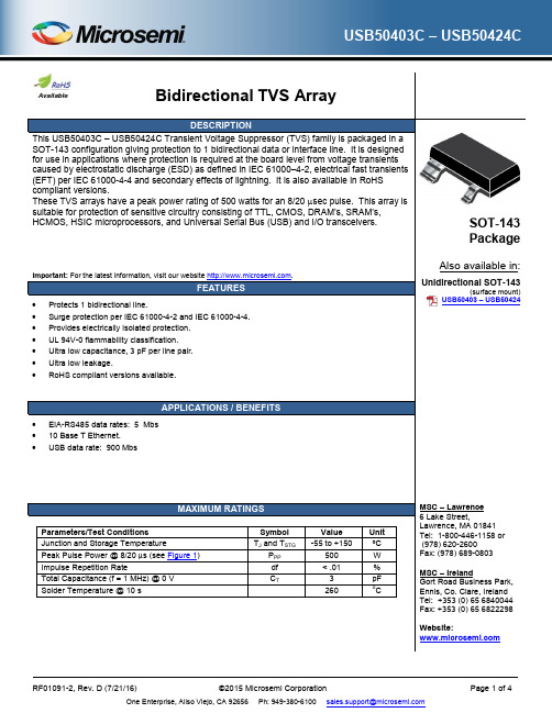
Available
Bidirectional TVS Array
DESCRIPTION
This USB50403C – USB50424C Transient Voltage Suppressor (TVS) family is packaged in a SOT-143 configuration giving protection to 1 bidirectional data or interface line. It is designed for use in applications where protection is required at the board level from voltage transients caused by electrostatic discharge (ESD) as defined in IEC 61000–4-2, electrical fast transients (EFT) per IEC 61000-4-4 and secondary effects of lightning. It is also available in RoHS compliant versions. These TVS arrays have a peak power rating of 500 watts for an 8/20 sec pulse. This array is suitable for protection of sensitive circuitry consisting of TTL, CMOS, DRAM’s, SRAM’s, HCMOS, HSIC microprocessors, and Universal Serial Bus (USB) and I/O transceivers.
太阳能系统控制器 ISC5040 使用说明书
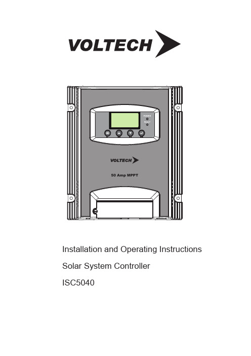
POWERFAULT50 Amp MPPTInstallation and Operating Instructions Solar System ControllerISC5040ABOUT THIS MANUALThese operating instructions come with the product and should be kept with it as a reference to all user’s of the product.Read these operating instructions carefully before use,Keep them over the entire life of the product,And pass then on to any future owner or user of this product.This manual describes the installation, function, operation and maintenance of the solar system controller ISC5040.These operating instructions are intended for end customers. A technical expert must be consulted in cases of uncertainty.SAFETY1. The solar controller may only be used in PV systems for charging Lead-Acid type batteries. This includes: SLA, VRLA, Lead-Calcium, AGM and GEL.Note; User’s should always refer to battery manufacturer/supplier’s recommended values for battery charging settings and float voltage setting.2. No energy source other than a solar panel (PV) may be connected to the solar charge controller.3. Do not connect any defective or damaged measuring equipment.4. Follow the general and national safety and accident prevention regulation.5. Never alter or remove the factory plates and identification labels.6. Keep children away from PV & Battery systems.7. Never open the device. (No user serviceable parts inside)8. One set solar module can connect with one controller only.9. Never touch bare cables.OTHER RISKSDanger of fire and explosionDo not use the solar charge controller in dusty environments, in the vicinity of solvents orwhere inflammable gases and vapors can occur.No open fires, flames or sparks in the vicinity of the batteries.Ensure that the room is adequately ventilated.Check the charging process regularly.Follow the charging instructions of the battery manufacturer.Battery acidAcid splashes on skin or clothing should be immediately treated with soap suds and rinsedwith plenty of water.If acid splashes into the eyes, immediately rinse with plenty of water. Seek medical adviceFault behaviorOperating the solar charge controller is dangerous in the following situations:The solar charge controller does not appear to function at all.The solar charge controller or connected cables are visibly damaged.Emission of smoke or fluid penetration.When parts are loose.If any of these occur, immediately disconnect the solar charge controller from the solar panels and battery.FunctionThis solar system controller is designed toMonitor the state of charge of the battery;Controls the charging process,Make sure Solar system works at proper condition.Charging Voltage is user programmable.OPERATING THE CONTROLLERThe display shows a variety of system data by symbols and digits. Both buttons control all settings and display windows.1. Display and operation elements.POWERFAULT 50 Amp MPPT LCD display for controller information and messages. Power LEDFail LEDConfirmation button in program Mode (Enter button)Pagedown buttonPageup buttonMenu button for switching display And enter setting mode.2. Display window. Change the display windows with the “Menu” button; (e.g. for 12V battery) 1. The default window will show like below, battery voltage/capacity volume of the battery.2. Press “menu” button once to check charging current.1. Charging Voltage Check & Program Press “menu” button 3 times. Window will switch to show BULK voltage setting. To change this setting; Press “enter” button once, you can program charge voltage via Pageup/Pagedown button: 12V Battery(14.0V-14.8V);24V Battery(28.0V-29.5V);36V Battery(42.0V-44.3V);48V Battery(56.0V-59.0V) Press “enter” or “menu” button to save setting.2. Press “menu” button 4 times. Window will switch to show FLOAT voltage setting. To change this setting; Press “enter” button once; you can program Float voltage via Pageup/Pagedown button: 12V Battery(13.0V-13.8V);24V Battery(26.0V-27.5V);36V Battery(39.0V-41.3V);48V Battery(52.0V-55.0V)Press “enter” or “menu” button to save setting.3.How to set up BULK/FLOAT voltage and DC load output function.3. Note :When the "Sensor Temp" port is inserted into the temperature sensor,Float voltage will vary accordingly to the ambient temperatures stated below:12V system: ≤0℃(14.1V), 0℃ - 20℃ (13.8V), ≥20℃ (13.5V);24V system: ≤0℃(28.2V), 0℃ - 20℃ (27.6V), ≥20℃ (27.0V);36V system: ≤0℃(42.3V), 0℃ - 20℃ (41.4V), ≥20℃ (40.5V);48V system: ≤0℃(56.4V), 0℃ - 20℃ (55.2V), ≥20℃ (54.0V);FEATURES1. Use with 12V/24V/36V/48V battery bank, the controller will detect voltage of battery automatically. With 3 charging stage: MPPT,constant voltage charging, and float charging, they are automatically performed.2. MPPT function - Implementing the latest MPPT technology the controller is able to harness the panels maximum available output at all times.3. Temperature CompensationISC5040 has an internal ambient temperature sensor that compensates during the float mode. INSTALLATION Install the controller in a ventilated area away from flammable materials and gases.The surface should be solid, even, dry and nonflammable.The battery to controller cable should be as short as possible (1-2mtrs is ideal) and be of a suitable diameter to minimize voltage loss.Do not assemble outdoor, the unit should be installed in the way to be protected against humidity, dripping, rainwater as well as direct and indirect heat (sunlight).To ensure the air circulation for cooling an area of 15cm on each side of the unit must be kept free.The LCD display should be protected against UV rays (e.g. sunlight). Long time exposure to UV rays can permanently discolor the LCD.The solar charge controller may only be connected to the local loads and the battery by trained personnel and in accordance with any applicable regulations.Follow the installation and operating instructions for all components of the PV system.Ensure that no cables are damaged.Ensure that polarity of Solar panel/battery/load is correct and use only insulated tools. WARNINGISC5040 can work with input voltage up to 95 Vdc maximum; when installing at this voltage, particularly with regard to module open circuit voltage (Voc), the entire solar energy system must be installed with protection class II. Cover solar modules during installation and use only insulated tools. 4. When the unit is in the default display mode, Pressing the “enter”button will turn the load ON or OFF manually.The arrow/lamp symbol will be displayed when the load terminal is ON.4. DC Load Output12/24/36/48V Max Output Current 50 A.DC load external power supply or battery is prohibited.CONNECTING / DIS-CONECTING SYSTEM SEQUENCEConnect the wires in the sequence from 1 to 6 according the above diagram; when Disconnect the wires in the REVERSE sequence from 6 to 1 according the above diagram.Use with 12V/24V/36V/48V battery bank, (controller will detect voltage of battery automatically).Never exceed the nominal ratings (see below technical data for reference).Suggested cable length, 10m solar panel connection cable/2m battery connection cable.Note : solar input is disconnecting and then reconnection, It need more than 5 seconds.1. Attention when connection:A: you need confirm the battery if it is 12V/24V36V/48V, the unit just can use 12V/24V36V/48V Lead-Acid battery and can’t for other specifications of the battery now.B: Solar panels open circuit voltage (VOC): the system of 12V battery for 16-95VDC solar panelthe system of 24V battery for 32-95VDC solar panelthe system of 36V battery for 48-95VDC solar panelthe system of 48V battery for 64-95VDC solar panel2.how to choose each connection cable:A: The requirements of PV panel to controller cable: PV1-F cable, PV TUV 2PFG 1169 length less than 8 meters, diameter 8-10 B: The requirements of battery to controller cable:UL1015 or same specification. Pure copper cable, length of 8AWG cable is 1.45 meters or length of 10AWG cable is 0.9 meter. Length tolerance of cable allowed only 5 mm. otherwise there will be big effect to charging voltage. ③④①②⑤⑥Max.650W PV array for 12V batteryMax.1300W PV array for 24V/36V/48V batteryTECHNICAL INFORMATIONCHARGING CURVEBulk: This is the first stage (MPPT) where the battery is in a low charge state. During this stage the controller delivers all of the available solar power to the Battery system.Absorption: In this stage (Constant Voltage) the controller charges at a constant voltage as the amount of current required to charge the battery is decreasing. The constant voltage regulation prevents overheating and excessive battery out-gassing; this stage will end when the battery charge current reduces to below 4 Amps OR after 4 hours of entering absorption mode.Float (Maintenance): After the battery is fully charged, the controller reduces to a lower Constant Voltage setting to maintain the Battery (also called trickle charge).PROTECTION FUNCTIONSOvercharge protectionBattery under-voltage protectionSolar panel reverse current protectionThe following installation faults do not destroy the controller. After correcting the fault, the device willcontinue to operate correctly:Overcharge protectionReverse polarity protection of panel and batteryAutomatic electronic fuseOpen circuit protection without batteryReverse current protection at nightW 056y r e t t a B V 21@ )x a m P (r e w o P y a r r A V P .x a M W 0031y r e t t a B V 84/63/42@ )x a m P (r e w o P y a r r A V P .x a M C D V 59)C O V ( e g a t l o V y a r r A V P .x a M C D V 67-61 e g n a R e g a t l o V T P P M y a r r A V P C D V 59-61y r e t t a B V 21@ e g n a R e g a t l o V t i u c r i c n e p o y a r r A V P C D V 59-23y r e t t a B V 42@ e g n a R e g a t l o V t i u c r i c n e p o y a r r A V P C D V 59-84y r e t t a B V 63@@ e g n a R e g a t l o V t i u c r i c n e p o y a r r A V P C D V 59-46yr e t t a B V 84 e g n a R e g a t l o V t i u c r i c n e p o y a r r A V P PV Input %99≥y c n e i c i f f e T P P M C D V 84/V 63/V 42/V 21e g a t l o V d e t a R y r e t t a B C D A 05t n e r r u C g n i g r a h C y r e t t a B V 21 C D A 05t n e r r u C g n i g r a h C y r e t t a B V 42 C D A 53t n e r r u C g n i g r a h C y r e t t a B V 63 C D A 52t n e r r u C g n i g r a h C y r e t t a B V 84Adjustable Charge Voltage(Bulk)14. 0-14. 8V/28. 0-29. 5V/42. 0-44. 3V/56. 0-59. 0V Output Adjustable Charge Voltage(Float)13. 0-13. 8V/26. 0-27. 5V/39. 0-41. 3V/52. 0-55. 0V A m 06t n e r r u c y b d n a t s t h g i N .x a MC °05+/C °01- e g n a R e r u t a r e p m e T g n i t a r e p O Max. Load Current DC Load output voltage Battery Voltage Over Discharge Voltage11.3/22.6/34.2/45.650A DCLoadOutputMAINTANANCEThe controller is maintenance-free. We strong suggest that all components of the PV system must be checked at least annually,Ensure adequate ventilation of the cooling elementCheck the cable strain reliefCheck that all cable connections are secureTighten screws if necessaryTerminal corrosion ERROR MESSAGESCaution! Please do not open the controller or attempt to replace components when troubleshooting. Improper maintenance can be hazardous to the user and the system.If the controller detects errors or unauthorized operating states, it shows error codes on the display. Error codes can generally be differentiated, whether there is a temporary malfunction, e.g. regulator overload or a more serious system error that can be remedied by appropriate external measures.Since not all errors can be simultaneously displayed, the error with the highest error number (priority) is displayed. If several errors are present, the second error code is displayed after remedying the more significant error.The Remark: When PV connected into the system, while battery disconnected, E1 and E2 may occur. This is normal. following meaning is assigned to the different error codes:1.Meaning: Battery reverse polarity warning, Red LED is shining.Remedy: Reconnect battery correctly. 2. 3.4. Meaning: Battery Voltage (Too high or too low), Red LED is shining.Remedy: Check battery voltage it might be too low or too high, possible recharge battery manually. If battery can’t be recharged, Replace battery & re-check.Meaning: Temperature is too high for the unit.Red LED is shiningRemedy:Stop charging for a while to cool down the unit.Meaning: Over current at the load output.Red LED is shining。
轻型客车产品描述解析

产品描述企业名称:xxxxx自动车工业有限公司注册商标:xx车辆类型:M2类型号和名称:GDQ6480A1系列轻型客车1 单元车型概况该单元包括5种车型,它们分别是GDQ6480A、GDQ6480A1、GDQ6480A1B、GDQ6480A1G、GDQ5020XQC,其中GDQ6480A1为基本车型。
该单元车型有6480、6480B等两种车身(驾驶室),有491Q—E、4G64 S4M(LJ486QE1)等两种发动机,有5RYA-4.9、035D等两种变速器,有2600一种轴距。
(单元中的非典型车型与典型车型的差异描述)见附件。
(典型的车型外廓尺寸简图和典型车型的正前、正后、正左、正右、正前45外观照片及同单元中其他车型的正前45度)见附件。
(典型的制动系统工作示意和管路布置图)见附件。
(典型的操纵件、指示器、信号装置图形标志说明及示意图)见附件。
(典型的照明及信号装置的安装位置示意图)见附件。
注:本描述适用车型M、N(包括二类底盘)0 类的机动车辆,对于其中不适合的项目、可以免填;对于专用汽车除填写此表外,还应进行专用装置描述(详见专用汽车参数表)。
2 车型结构及主要技术参数2.1 整车(1)是指M1~M3、N1~N3、O1~O4。
(2)是指长头、半长头、平头;单排、排半、双排、带卧铺;单厢、两厢、三厢;封闭式、敞蓬式;硬顶、软顶等。
(3)是指栏板式、罐式、槽式、仓栏式;敞开式、封闭式等。
(4)是指二类(带驾驶室)、三类(不带驾驶室)。
(5)是指前置、中置、后置;纵向、横向。
(6)是指机械式、液力机械式、静液式、电力式。
(7)是指机械式、液力式;干式、湿式;膜片弹簧式、螺旋弹簧式;单片、双片等。
(8)是指手动、自动、无级变速等。
(9)包括操纵方式、传能方式、传能介质、助力方式、制动力调节方式、制动器型式。
:(10)对于半挂车是指牵引销轴线与第一轴线间的距离、其它轴线与轴线间的距离用加法数学式子表达;对于其它类型车是指轴线与轴线间的距离用加法数学式子表达。
