H101CBC;中文规格书,Datasheet资料
BDC01DRL1G;中文规格书,Datasheet资料
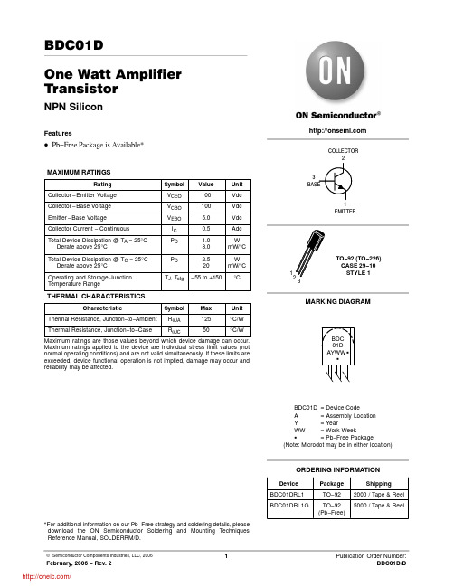
BDC01DOne Watt Amplifier TransistorNPN SiliconFeatures•Pb−Free Package is Available*MAXIMUM RATINGSRating Symbol Value Unit Collector−Emitter Voltage V CEO100Vdc Collector−Base Voltage V CBO100Vdc Emitter−Base Voltage V EBO 5.0Vdc Collector Current − Continuous I C0.5AdcTotal Device Dissipation @ T A = 25°C Derate above 25°C P D 1.08.0WmW/°CTotal Device Dissipation @ T C = 25°C Derate above 25°C PD 2.520WmW/°COperating and Storage JunctionTemperature RangeT J, T stg−55 to +150°C THERMAL CHARACTERISTICSCharacteristicSymbol Max Unit Thermal Resistance, Junction−to−Ambient R q JA125°C/W Thermal Resistance, Junction−to−Case R q JC50°C/W Maximum ratings are those values beyond which device damage can occur. Maximum ratings applied to the device are individual stress limit values (not normal operating conditions) and are not valid simultaneously. If these limits are exceeded, device functional operation is not implied, damage may occur and reliability may be affected.*For additional information on our Pb−Free strategy and soldering details, please download the ON Semiconductor Soldering and Mounting Techniques Reference Manual, SOLDERRM/D.Device Package ShippingORDERING INFORMATIONBDC01DRL1TO−922000 / Tape & ReelBDC01DRL1G TO−92(Pb−Free)5000 / Tape & ReelCOLLECTOR31EMITTERELECTRICAL CHARACTERISTICS (T A = 25°C unless otherwise noted)CharacteristicSymbolMinMaxUnitOFF CHARACTERISTICS Collector −Emitter Voltage(I C = 10 mA, I B = 0)V (BR)CEO 100−Vdc Collector Cutoff Current(V CB = 100 V, I E = 0)I CBO −0.1m Adc Emitter Cutoff Current(I C = 0, V EB = 5.0 V)I EBO−100nAdcON CHARACTERISTICSDC Current Gain(I C = 100 mA, V CE = 1.0 V)(I C = 500 mA, V CE = 2.0 V)h FE4025400−−Collector −Emitter Saturation Voltage (Note 1)(I C = 1000 mA, I B = 100 mA)V CE(sat)−0.7Vdc Collector −Emitter On Voltage (Note 1)(I C = 1000 mA, V CE = 1.0 V)V BE(on)−1.2VdcDYNAMIC CHARACTERISTICSCurrent Gain Bandwidth Product(I C = 200 mA, V CE = 5.0 V, f = 20 MHz)f T 50−MHz Output Capacitance(V CB = 10 V, I E = 0, f = 1.0 MHz)C ob−30pF1.Pulse Test: Pulse Width v 300 m s; Duty Cycle2.0%.Figure 1. DC Current GainI C , COLLECTOR CURRENT (mA)4000.50.7 1.0 2.0 3.0 5.07.01020305070100200200100806040h F E , D C C U R R E N T G A I N300500I B , BASE CURRENT (mA)Figure 2. Collector Saturation Region V C E , C O L L E C T O R −E M I T T E R V O L T A G E (V O L T S1.00.60.40.20I C , COLLECTOR CURRENT (mA)Figure 3. “On” VoltagesV , V O L T A G E (V O L T S )I C , COLLECTOR CURRENT (mA)Figure 4. Base−Emitter Temperature Coefficient −0.8−2.8−1.2−1.6−2.0−2.4V B , T E M P E R A T U R E C O E F F I C I E N T (m V /C )°θC , C A P A CI T A N CE (pF )Figure 5. CapacitanceV R , REVERSE VOLTAGE (VOLTS)80604020104.08.06.0Figure 6. Current−Gain — Bandwidth Product I C , COLLECTOR CURRENT (mA)300200100705030f , C U R R E N T −G A I N Ċ B A N D W I D T H P R O D U C T (M H z )T V CE , COLLECTOR−EMITTER VOLTAGE (VOLTS)2 k 1.0I C , C O L L E C T O R C U R R E N T (m A )2.0 5.0Figure 7. Active Region — Safe Operating Area500200100502010102060801001 kPACKAGE DIMENSIONSTO−92 (TO−226)CASE 29−10ISSUE ALNOTES:1.DIMENSIONING AND TOLERANCING PER ANSI Y14.5M, 1982.2.CONTROLLING DIMENSION: INCH.3.CONTOUR OF PACKAGE BEYOND DIMENSION R IS UNCONTROLLED.4.DIMENSION F APPLIES BETWEEN P AND L.DIMENSIONS D AND J APPLY BETWEEN L AND K MIMIMUM. LEAD DIMENSION IS UNCONTROLLED IN P AND BEYOND DIMENSION K MINIMUM.DIM MIN MAX MIN MAX MILLIMETERSINCHES A 0.1750.205 4.44 5.21B 0.2900.3107.377.87C 0.1250.165 3.18 4.19D 0.0180.0210.4570.533F 0.0160.0190.4070.482G 0.0450.055 1.15 1.39H 0.0950.105 2.42 2.66J 0.0180.0240.460.61K 0.500−−−12.70−−−L 0.250−−− 6.35−−−N 0.0800.105 2.04 2.66P −−−0.100−−− 2.54R0.135−−−3.43−−−STYLE 14:PIN 1.EMITTER2.COLLECTOR3.BASEON Semiconductor and are registered trademarks of Semiconductor Components Industries, LLC (SCILLC). SCILLC reserves the right to make changes without further notice to any products herein. SCILLC makes no warranty, representation or guarantee regarding the suitability of its products for any particular purpose, nor does SCILLC assume any liability arising out of the application or use of any product or circuit, and specifically disclaims any and all liability, including without limitation special, consequential or incidental damages.“Typical” parameters which may be provided in SCILLC data sheets and/or specifications can and do vary in different applications and actual performance may vary over time. All operating parameters, including “Typicals” must be validated for each customer application by customer’s technical experts. SCILLC does not convey any license under its patent rights nor the rights of others. SCILLC products are not designed, intended, or authorized for use as components in systems intended for surgical implant into the body, or other applications intended to support or sustain life, or for any other application in which the failure of the SCILLC product could create a situation where personal injury or death may occur. Should Buyer purchase or use SCILLC products for any such unintended or unauthorized application, Buyer shall indemnify and hold SCILLC and its officers, employees, subsidiaries, affiliates,and distributors harmless against all claims, costs, damages, and expenses, and reasonable attorney fees arising out of, directly or indirectly, any claim of personal injury or death associated with such unintended or unauthorized use, even if such claim alleges that SCILLC was negligent regarding the design or manufacture of the part. SCILLC is an Equal Opportunity/Affirmative Action Employer. This literature is subject to all applicable copyright laws and is not for resale in any manner.PUBLICATION ORDERING INFORMATION分销商库存信息: ONSEMIBDC01DRL1G。
RP101中文资料

Reverse Voltage, (Volts) FIGURE 4. TYPICAL JUNCTION CAPACITANCE
TRR 0.5
(+)
25 VDC (APPROX)
D.U.T.
(-)
PULSE GENERATOR (Note 2)
SYMBOL
RATINGS
RP100 RP101 RP102 RP104 RP106 RP108 RP110
UNITS
VRM VRMS VRRM IO IFSM VFM TRR IRM RθJA CJ TJ, TSTG
50 35 50
100 70 100
200 140 200
400 280 400 1
10
100
T J = 25 oC
1.0
f = 1 MHz
10
0.1
TJ = 25 oC Pulse Width = 300 µS 1% Duty Cycle
0.01
0.1 0.1
1
10
Instantaneous Forward Voltage (Volts) FIGURE 3. TYPICAL FORWARD CHARACTERISTIC
20
10
Ambient Temperature, oC FIGURE 1. FORWARD CURRENT DERATING CURVE
0 1 10 100
Number of Cycles at 60 Hz FIGURE 2. MAXIMUM NON-REPETITIVE SURGE CURRENT
H23
DIOTEC ELECTRONICS CORP.
UDZSTE-1711B;中文规格书,Datasheet资料
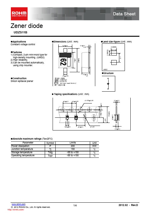
Land size figure (Unit : mm)
0.9MIN. 0.8MIN.
1.7±0.1
2.5±0.2
UMD2
0.7±0.2 0.1
Structure
0.3±0.05
Construction Silicon epitaxial planar
20 19 CAPACITANCE BETWEENTERMINALS:Ct(pF) 18 17 16 15 14 13 12 11 10 AVE:16.76pF Ta=25℃ f=1MHz VR=0V n=10pcs
11.8 ZENER VOLTAGE:Vz(V)
11.7
11.6
11.5 AVE:10.943V 11.4
0.1 0.001
0.01
0.1
1
10
100
TIME:t(ms) PRSM-TIME CHARACTERISTICS 1000 Rth(j-a)
100
Rth(j-c)
10
Mounted on epoxy board IM=10mA IF=100mA
1
1ms time
300us
0.1 0.001
0.01
Zener diode
UDZS11B
Applications Constant voltage control Features 1) Compact, 2-pin mini-mold type for high-density mounting. (UMD2) 2) High reliability. 3) Can be mounted automatically, using chip mounter. Dimensions (Unit : mm)
BW产品规格书
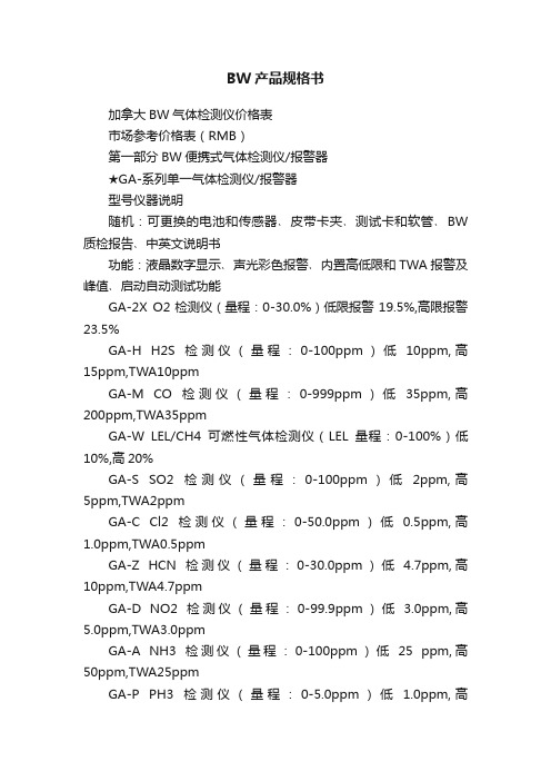
BW产品规格书加拿大BW气体检测仪价格表市场参考价格表(RMB)第一部分BW便携式气体检测仪/报警器★GA-系列单一气体检测仪/报警器型号仪器说明随机:可更换的电池和传感器﹑皮带卡夹﹑测试卡和软管﹑BW 质检报告﹑中英文说明书功能:液晶数字显示﹑声光彩色报警﹑内置高低限和TWA报警及峰值﹑启动自动测试功能GA-2X O2检测仪(量程:0-30.0%)低限报警19.5%,高限报警23.5%GA-H H2S检测仪(量程:0-100ppm)低10ppm,高15ppm,TWA10ppmGA-M CO检测仪(量程:0-999ppm)低35ppm,高200ppm,TWA35ppmGA-W LEL/CH4可燃性气体检测仪(LEL量程:0-100%)低10%,高20%GA-S SO2检测仪(量程:0-100ppm)低2ppm,高5ppm,TWA2ppmGA-C Cl2检测仪(量程:0-50.0ppm)低0.5ppm,高1.0ppm,TWA0.5ppmGA-Z HCN检测仪(量程:0-30.0ppm)低 4.7ppm,高10ppm,TWA4.7ppmGA-D NO2检测仪(量程:0-99.9ppm)低 3.0ppm,高5.0ppm,TWA3.0ppmGA-A NH3检测仪(量程:0-100ppm)低25 ppm,高50ppm,TWA25ppmGA-P PH3检测仪(量程:0-5.0ppm)低 1.0ppm,高★GAXT-系列防水型单一气体检测仪/报警器型号仪器说明随机:可更换电池和传感器﹑不锈钢卡夹﹑测试卡帽和软管﹑BW 质检报告﹑中英文说明书功能:密封防护等级IP66/67防水防雨防尘,内置振动功能;液晶数字显示﹑声光报警﹑内置高低限和TWA/STEL报警及峰值﹑启动自动GAXT-X O2检测仪(量程:0-30.0%)低限报警19.5%,高限报警22.5%GAXT-H H2S检测仪(量程:0-100ppm)低10ppm,高15ppm,TWA 10ppmGAXT-M CO检测仪(量程:0-999ppm)低35ppm,高200ppm,TWA 35ppmGAXT-S SO2检测仪(量程:0-100ppm)低2ppm,高5ppm,TWA 2ppmGAXT-C Cl2检测仪(量程:0-50.0ppm)低0.5ppm,高1.0ppm,TWA0.5ppmGAXT-Z HCN检测仪(量程:0-30.0ppm)低4.7ppm,高10ppm,TWA4.7ppmGAXT-D NO2检测仪(量程:0-99.9ppm)低2.0ppm,高5.0ppm,TWA2.0ppmGAXT-A NH3检测仪(量程:0-100ppm)低25 ppm,高50ppm,TWA25ppmGAXT-P PH3检测仪(量程:0-5.0ppm)低0.3ppm,高1.0ppm,TWA 0.3ppmGAXT-G O3检测仪(量程:0-1.0ppm)低0.1ppm,高0.2ppm,TWA 0.1ppmGAXT-E ETO检测仪(量程:0-100.0ppm)低1ppm,高5ppm,TWA1ppmGAXT-N NO检测仪(量程:0-250ppm)低25 ppm,高GAXT-V ClO2检测仪(量程:0-1.0ppm)低0.1ppm,高0.3ppm,TWA0.1ppm选存储器出厂设置5秒/组数据,一个月数据存储量,可设1-60秒/组★MC系列多功能气体检测仪﹡可选二、三、四种气体型号仪器说明随机:可更换的电池和传感器﹑皮带卡夹﹑测试卡帽和软管﹑BW 质检报告﹑中英文说明书功能:液晶数字显示﹑声光报警﹑内置设定高低限报警TWA显示﹑启动自动测试功能MC-4四合一气体检测:%LEL,O2,CO,H2S;MC-3H三合一气体检测:%LEL,O2,H2S;MC-3M三合一气体检测:%LEL,O2,CO;MC-3S三合一气体检测:%LEL,O2,SO2;MC-2二合一气体检测:%LEL,O2;MC-2HW二合一气体检测:%LEL,H2S;选:DL2-IR数据32MB MMC存储卡和免费软件CD-ROM选:-C01-K4节AA NiMH充电电池和一个220VAC四座充电器型号仪器说明GAMAX XT II-4四合一气体检测:%LEL,O2,CO,H2S;GAMAX XT II-3H三合一气体检测:%LEL,O2,H2S;GAMAX XT II-2二合一气体检测:%LEL,O2;M5型号随机:电池和被测传感器﹑皮带卡夹﹑测试卡帽和软管﹑BW 质检报告﹑中英文说明书功能:液晶数字显示﹑声光报警﹑内置设定高低限报警TWA 显示﹑启动自动测试功能主机随机:220VAC 两座充电器带1节充电镍锰或镍锌电池﹑可更换的传感器﹑内置采样气泵和3米采样软管和标定软管﹑携带保护外套﹑过滤功能:大屏幕液晶显示,声光彩色报警,内设高低限TWA 报警, 启动自动测试功能,使用者可根据需要设置高低报警点★ GAMAX XT II-多功能气体检测仪﹡可选二、三、四种气体选件3:可加装有毒气体传感器2(只能选择其一)①. COSH ¥3840;②.H2S ¥2730;③.CO ¥2860;④.SO2,Cl2,ClO2,NH3,P H3,HCN,NO2,O3 单价均为¥4300, PID ¥8500选件4:电池选件 0.碱性电池¥0 ;1.可充电镍锰电池NiMH 和充电器¥2200选件1:可燃性气体和氧气传感器(只能选择其一)①.LEL 可燃性气体¥2500;②.O2氧气¥1980;③.LEL/O2可燃性气体和氧气¥4500选件2:可加装有毒气体传感器1(只能选择其一)①.H2S ¥2730;②.CO ¥2860;③.SO2,Cl2,ClO2,NH3,PH3,HCN,NO2,O3 单价均为¥4300选件5:采样方法:0.扩散式¥0 ;1.电动泵吸式¥3500选件6:数据记录: 0.无数据记录¥0 ;1. 32MB 数据记录卡和软件¥1500★GasAlertMicro5-系列多功能气体检测仪﹡可选一、二、三、四、五种气体型号仪器说明监测:环境温度T°,相对湿度RH ,CO2, CO;范围:CO 0-250ppm 或500ppm(可选择);温度T°0℃-40℃CO2 0-5.000或0-10.000ppm(可选择);RH 0-95%监测:环境温度T°,相对湿度RH ,CO2;范围:环境温度T°0-40℃ ,相对湿度RH 0-95%CO2 0-5.000或0-10.000ppm(可选择);监测:CO2, CO;范围:CO 0-250ppm 或500ppm(可选择);CO2 0-5.000或0-10.000ppm(可选择);IAQ-1监测:CO2;范围: CO2 0-5.000或0-10.000ppm(可选择);选:-DL 数据存储卡及免费软件CD-ROM,下载数据读取器GAA-GA-系列加内置振动功能(适合于GA-系列单一气体检测仪)GA-SPAK自动采样气泵带采样软管3米及过滤器(适合于GA-,GAMIC-)D4-AS01手动采样气泵,带3米采样软管(适合于GA-,GAMIC-)GA-AS02手动采样气泵,带0.3米采样探管(适合于GA-,GAMIC-)随机:传感器﹑可充电的锂电池﹑AC 电源适配器﹑仪器﹑BW 质检报告﹑中英文说明书功能:大屏幕数字显示,声光彩色报警,内设高低限TWA 报警, 启动自动测试功能,可根据需要设置报警点★ GasProbe 空气质量监测仪第二部分 BW 在线式气体监测仪/变送器/接收器IAQ-4IAQ-3IAQ-2附件、选件、替换及配件:型号仪器说明CR-4000CR-4000四通道气体控制器(110VAC,230VAC 和24VDC )四通道气体接收控制器(不锈钢)-可移动声音报警蜂鸣器四SPDT 通道报警交替显示(失败、低、高、高-高报警)型号仪器说明GP-WD 可燃气体监测仪(0-100%LEL 催化传感器)GP-IR-WD 可燃气体监测仪(0-100%LEL 红外传感器)GP-HDH2S 气体监测仪﹡可选0-100/50/500/20/30/1000/200ppm GP-MDCO 气体监测仪﹡可选0-500/1000/100/50/200ppm GP-ADNH3气体监测仪﹡可选0-50/100/150/1000ppm GP-ZDHCN 气体监测仪﹡可选020.0/50.0/100ppm GP-DDNO2气体监测仪﹡可选0-10.0/20.0ppm GP-SDSO2气体监测仪﹡可选0-100/50/20/10/2.00ppm GP-CDCl2气体监测仪﹡可选0-5.0/10.0/100/500ppm GP-XDO2气体监测仪﹡可选0-25%/30%GP-SEP 传感器分离装置盒RRJ-4000隔爆型,三线4-20mA 可进控制系统(DCS,PLC 等)或BW 控制接收器CR-4000和RRJ-4000包括传感器、两个LCD 显示浓度和成份及状态,三个输出(低、高、失败),可选测量范围功能:可选BW 4-20mA 输出:GasPoint;I.S.Plant Rat;CD-420;ToxyPoint;RRJ Monitors特点:每通道单独显示,安装简单和维护方便,声音报警85dB, 高、低、失败三种报警,背光液晶显示,可选交直流供电115/230V AC 或CR-4000和RRJ-4000四通道气体控制接收器Gas Point 隔爆型4-20mA 信号输出气体监测仪型号仪器说明ISPR2-DH(#)H2S监测仪﹡可选0-100/50/500/20/30/1000/200ppm ISPR2-DM(#)CO监测仪﹡可选0-500/1000/100/50/200ppmISPR2-DX(#)O2监测仪﹡可选0-25%/30%ISPR2-DS(#)SO2监测仪﹡可选0-100/50/20/10/2.00ppmISPR2-DCCl2监测仪﹡可选0-5.0/10.0/100/500ppm ISPR2-DV(#)ClO2监测仪﹡可选0-5.00/1.00ppmISPR2-DA(#)NH3监测仪﹡可选0-50/100/150/1000ppm ISPR2-DZ(#)HCN监测仪﹡可选020.0/50.0/100ppm ISPR2-DD(#)NO2监测仪﹡可选0-10.0/20.0ppmISPR2-DN(#)NO监测仪﹡可选0-50/100ppmISPR2-DL(#)HCl监测仪﹡可选0-10.0/20.0/100ppm ISPR2-DB(#)C2H6O监测仪﹡可选0-10.0/20.0ppm ISPR2-DE(#)C2H4O监测仪﹡可选0-10.0/20.0/100ppm ISPR2-DY(#)H2监测仪﹡可选0-100/200/800ppm ISPR2-DGO3监测仪﹡可选0-1.00/2.00ppmISPF5-D(x#)I.S.Plant Rat 加气体取样装置,每单元加收不要显示模块监测仪无显示,替换本安防爆型,两线4-20mA 可进控制系统(DCS,PLC等)或BW 控制接收器CR-4000和RRJ-4000包括传感器、可选测量范围、数字显示、模块化设计、标定卡帽、标定工具和仪器I.S.Plant Rat 在线式4-20mA有毒/氧气气体监测仪CD-420通用型4-20mA有毒和氧气气体监测变送器型号仪器说明CD-420-3H H2S 监测变送器﹡可选0-100ppm/0-50ppm/0-500ppm CD-420-3A NH3监测变送器﹡可选0-100ppm/0-500ppm CD-420-3C Cl2监测变送器﹡可选0-100ppm/0-20ppmCD-420-3S SO2监测变送器﹡可选0-50ppm/0-20ppm/0-10ppmCD-420-3DNO2监测变送器﹡可选0-10ppm/0-20ppm CD-420-3M CO 监测变送器可选0-500ppm/1000ppm/100ppm/200ppmCD-420-3X O2监测变送器﹡可选0-25%/0-30%型号仪器说明RRJ-RW04可燃气体(0-100%LEL )传感器输出4-20mA,3线RRJ-RH04H2S(0-100ppm)传感器输出4-20mA,2线RRJ-RX04O2(0-25%)传感器输出4-20mA,2线RRJ-RM04CO(0-500ppm)传感器输出4-20mA,2线型号仪器说明AR-PRH(#)-2D H2S 监测仪﹡可选0-100/50/500/20/30/1000/200ppm AR-PRM(#)-2D CO 监测仪﹡可选0-500/1000/100/50/200ppm AR-PRX1(#)-2D O2监测仪﹡可选0-25%V/VRRJ 系列—两年质保包括传感器,零维护4-20mA 输出气体传感器/输出本安防爆型,101dB 声音警报和LED 显示,蜂鸣器和四继电输出(失败、低、高、高-高报警),3位半液晶现场显示NEMA 4X 外壳,对Alarm Rat 单点AC/DC 在线式有毒/氧气气体监测仪监测空气中有毒/氧气浓度,两线4-20mA 输出,包括传感器、标定卡帽、标定工具和仪器输出4-20mA 信号进控制系统(DCS,PLC 等)或BW 控制接收器CR-4000或RRJ-4000AR-PRS(#)-2D SO2监测仪﹡可选0-100/50/20/10/2.00ppm AR-PRC(#)-2D Cl2监测仪﹡可选0-5.0/10.0/100/500ppmAR-PRV(#)-2D ClO2监测仪﹡可选0-5.00/1.00ppmAR-PRA(#)-2D NH3监测仪﹡可选0-50/100/150/1000ppmAR-PRZ(#)-2D HCN监测仪﹡可选020.0/50.0/100ppmAR-PRD(#)-2D NO2监测仪﹡可选0-10.0/20.0ppmAR-PRN(#)-2D NO监测仪﹡可选0-50/100ppmAR-PRL(#)-2DHCl监测仪﹡可选0-10.0/20.0/100ppmAR-PRB(#)-2D C2H6O监测仪﹡可选0-10.0/20.0ppmAR-PRE(#)-2DC2H4O监测仪﹡可选0-10.0/20.0/100ppmAR-PRY(#)-2D H2监测仪﹡可选0-1.00/2.00ppmAR-PR(x#)-3DAlarm Rat 带4-20mA输出,后缀加“-3D”不要显示模块监测仪无显示,替换MB)气体检测仪/报警器价格已停产已停产已停产已停产已停产已停产已停产已停产已停产已停产价格高低限和TWA/STEL报警及峰值﹑启动自动测试功能﹑多种语言显示选择¥6000.00¥6000.00¥6000.00¥7500.00¥7500.00¥7500.00¥7500.00¥7500.00¥7500.00¥7500.00¥7500.00¥7500.00¥7500.00加¥1500.00 价格¥12000.00¥11000.00¥11000.00¥12000.00¥8400.00¥9000.00加¥1500.00加¥600.00价格采样软管和标定软管﹑携带保护外套﹑过滤器﹑BW质检报告﹑中英文说明书据需要设置高低报警点¥17500.00¥17000.00¥15000.00仪器说明价格¥5800.00价格¥12000.00加¥3000.0060485180¥700.00¥3500.00¥1000.00¥1000.00置报警点体监测仪/变送器/接收器¥16500.00¥14000.00¥14000.00价格液晶显示,可选交直流供电115/230V AC或24V DC供电,防护等级NEMA 4X¥13800.00¥18000.00价格¥13800.00¥13800.00 ¥15300.00 ¥15300.00 ¥16700.00 ¥16700.00 ¥15300.00 ¥15300.00 ¥13500.00 ¥3500.00 价格¥11000.00 ¥11000.00 ¥11000.00 ¥12500.00 ¥12500.00 ¥12500.00 ¥12500.00 ¥13800.00 ¥13300.00 ¥13800.00 ¥13800.00 ¥13800.00 ¥13800.00 ¥13200.00 ¥13800.00 加¥6900.00 减¥1250.00 价格¥6900.00¥8300.00¥8300.00¥8300.00¥4500.00¥6300.00价格¥6500.00¥5400.00¥5400.00¥5400.00价格),3位半液晶现场显示NEMA 4X外壳,对RFI/EMI屏蔽,可选测量范围¥22000.00¥22000.00¥22000.00¥23000.00¥23000.00¥23000.00¥23000.00¥24000.00¥24000.00¥24000.00¥24000.00¥24000.00¥24000.00¥24000.00加¥1400.00减¥1250.00。
汉彩10.1规格书 HSD101PFW1

H a n n Sta r Di sp l a y C o rp .
Document Title Document No. HSD101PFW1-A Product Information Page No. Revision 3/24
1.0 GENERAL DESCRIPTION
1.1 Introduction HannStar Display model HSD101PFW1-A is a color active matrix thin film transistor (TFT) liquid crystal display (LCD) that uses amorphous silicon TFT as a switching device. This model is composed of a TFT LCD panel, a driving circuit and a back light system. This TFT LCD has a 10.1 (16:9) inch diagonally measured active display area with WSVGA (1024 horizontal by 576 vertical pixel) resolution. 1.2 Features ■ 10.1 (16:9 diagonal) inch configuration ■ One channel LVDS interface ■ 262K color by 6 bit R.G.B signal input ■ RoHS Compliance ■ Halogen Free 1.3 Applications Mobile NB Digital Photo frame Display terminal for AV application 1.4 General information Item Outline Dimension Display area Number of Pixel Pixel pitch Pixel arrangement Display mode NTSC Surface treatment Weight Back-light Power Consumption Logic System B/L System
CBW系列大电流贴片磁珠规格书
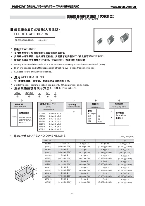
FERRITE CHIP BEADS
FERRITE CHIP BEADS
OPEARATING TEMP. -40 +85
FEATURES:
PCB EIA SMT EMI RFI
A unique terminal electrode structure ensures ensures permissible current 6.0A (max). High impedance and EMI suppression effective over a wide frequency range. Suitable reflow and wave soldering.
unit mm(inch) D 0.25 (0.010 0.3 (0.01 0.5 (0.020 0.5 (0.020 0.5 (0.020 0.5 (0.020 0.5 (0.020 0.10 0.004) 0.2 0.008) 0.3 0.012) 0.3 0.012) 0.3 0.012) 0.3 0.012) 0.3 0.012)
CBW
MULTILAYER CHIP POWER BEADS
SHAPE AND DIMENSIONS
Part No. 100505 (0402) 160808 (0603) 201209 (0805) 321609 L W T (1206) 322513 (1210) 451616 (1806) D 453215 (1812) 1.0 (0.040 1.6 (0.063 2.0 (0.079 3.2 (0.126 3.2 (0.126 4.5 (0.186 4.5 (0.180 L 0.15 0.006) 0.2 0.008) 0.2 0.008) 0.2 0.008) 0.2 0.008) 0.2 0.008) 0.2 0.008) 0.5 (0.020 0.8 (0.031 1.2 (0.047 1.6 (0.063 2.5 (0.098 1.6 (0.063 3.2 (0.126 W 0.15 0.006) 0.2 0.008) 0.2 0.008) 0.2 0.008) 0.2 0.008) 0.2 0.008) 0.2 0.008) 0.5 (0.020 0.8 (0.031 0.9 (0.035 0.9 (0.035 1.3 (0.051 1.6 (0.063 1.5 (0.060 T 0.15 0.006) 0.2 0.008) 0.2 0.008) 0.2 0.008) 0.2 0.008) 0.2 0.008) 0.2 0.008)
伊顿 EACB-101B 技术手册 - TMY0024.B - EN 说明书
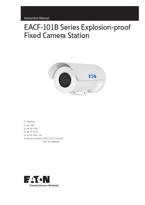
EACF-101B Series Explosion-proof Fixed Camera StationEx Marking:Ex db I MbEx db [ib] I MbEx db IIC T6 GbEx tb IIIC T80℃ DbCertificate numbers: IECEx ExTC 21.0013XBIS: R-41268585Copyright StatementCooper Yuhua (Changzhou) Electric Equipment Manufacturing Co., Ltd (hereinafter referenced as Cooper Yuhua). Claims copyright ownership of the contents (including text and images) of this Instruction Manual. Any content may not be copied, transferred, modified or reproduced by any person or organization without expressed permission of Cooper Yuhua.Cooper Yuhua remains the right to modify the content and technical specifications of the product in this Instruction Manual without any form of notification, in order to provide the newest and most advanced product. The end users can get the latest product information on Yuhua’s website:/yuhua-cctv Trademark statementThis is the trademark of Cooper Yuhua (Changzhou) Electric Equipment Manufacturing Co., Ltd., all right reversed. The other trademark and trademark right appeared in this Instruction Manual belongs to its legal holder.2EATON Quality GuaranteeFor EACF-101B explosion-proof fixed camera set, we provide free maintain service in the guarantee period, but we will ask the user to pay for the cost of labor and component in the follow conditions:• Damage caused by improper installation or operation and not in accordance with this instruction manual.• Damage caused by unauthorized disassembly.• Thunder or other force majeure natural disasters.If any other contracts between clients and us exist, we will follow the promise or regulation strictly.Security AssuranceOperation of this product fulfills the following two requirements:• No adverse interference in operation;• The operation of this product cannot be interfered by external factors even adverse interference.3EATON 4Installation instructions for EACF -101B CCTV camera stationEnglishEATON TMY0024 August 2024 Notice•The user shall not disassemble this product optionally, such as remove the top cover or bolts may cause leakage of water or electricity. Please operate the product according to the requirements in this Instruction Manual;•Ensure this product is always used in environment with atmosphere pressure, ambient temperature and relative humidity specified in Chapter 1.6;•To be sure the power supply complies with the requirement indicated in the nameplate;• The internal and external grounding shall be reliable;•Ensure the installation is firm and reliable, to avoid unexpected damage of the camera;•Protect the flame-proof joints from stumble and crack in installation, operation and maintenance.Thank you for selecting Cooper Yuhua product!Please read this Instruction Manual carefully beforeInstallation, operation and maintenance of this product and follow the manual. Please keep this manual properly.5Installation instructions for EACF -101B CCTV camera stationEnglishEATON TMY0024 August 2024 ContentCopyright Statement ...........................................................................................................................2T rademark statement ..........................................................................................................................2Quality Guarantee ...............................................................................................................................3Security Assurance ..............................................................................................................................3Notice .................................................................................................................................................4Ex structure instruction ......................................................................................................................71.0 General . (7)1.1 Type and model ..........................................................................................................................71.2 Features .....................................................................................................................................81.3 Scope .........................................................................................................................................81.4 Mechanical data .........................................................................................................................81.5 Electrical data .............................................................................................................................81.6 Service condition .......................................................................................................................81.7 Electrical safeties (standard atmospheric pressure) ..................................................................82.0 Installation & debugging . (9)2.1 Cautions.....................................................................................................................................92.2 Wall mount installation ..............................................................................................................92.3 Grounding .................................................................................................................................92.4 Wiring .......................................................................................................................................93.0 T roubleshooting ...........................................................................................................................104.0 Transportation and storage .. (10)4.1 Cautions in hoisting and transportation ...................................................................................104.2 Storage condition, duration and cautions ................................................................................105.0 Specification of internal camera module ..................................................................................10Annex 1: Table of poisonous and harmful substances or elements .. (11)6Installation instructions for EACF -101B CCTV camera stationEnglishEATON TMY0024 August 2024 Safety RequirementPlease read this Instruction Manual carefully before installation and operation of this product.1. Safety cautions in installation•Cut off power supply before any maintenance or repair of the product.•Avoid opening of this product in environment where oil smoke, heavy dust, high temperature or dewing may exist. These will cause the decrease of the image definition.•Connect the cables according to the requirement indicated in the Instruction Manual, or fault may happen.•Protect the flame proof joint in maintenance; avoid any metal fragment or other substances get access in the internal chamber.•No disassembly or modification allowed.2. Construction Safety•The protective regulations on construction spot shall be followed strictly.•Measurement shall be carried out immediately when any security risks found to eliminate the risks, stop construction if necessary.•All kinds of safety facilities shall be inspected, calibrated or repaired in the event of severe weather.• The ice, fog, rain and snow shall be removed before opening.•Alert area shall be set, and a person shall protect thearea when protective casing and other safety facilities are constructed or dismantled.•Work high above the ground may require in installation of this product, the operating personnel shall be qualified.3. Power supply requirements•Local electrical safety standard shall be followed in installation and service of this product.•Convenient de-energizing device shall be adopted for immergence cutting off.• Check if the power supply is suitable for operation before start.•Protect the power cable from trample or compressing, especially for the plug, socket and joint out from devices.•Explosion-proof measurement is necessary for Ex products.4. Service condition requirements•Please do not focus the camera to hard light (such as lamp or sunlight), which will cause too bright of the image, it will not malfunction but it will affect the operational life of the CCD (or CMOS).•Transport, operate and store this product in applicable temperature and humidity range. Do not locate it in wet, overheated (over +60℃), extreme cold(less than -30℃)environment or area with strong electromagnetic radiation or power lighting conditions.•The product shall be protected from any entry of water or other conductive fluid, which may damage the internal electrical element.• Avoid overheated, the product shall be well ventilated. •Avoid damage caused by compressing or violent vibration in transmission, storage or operation.•The product shall be well packaged as new product or equivalent in transmission.• We suggest using this product with Surge Protection Devices.•Internal and external grounding shall be reliable.5. Operation & maintenance requirements•There is no user serviceable part inside of camera enclosure. Don’t dismantle this product unless it’s required for repair or maintenance.•Do not touch the front glass of the camera or internal camera lens directly. If it’s necessary to do cleaning please use soft cloth with alcohol to wipe gently.•The camera image sensor may be damaged by laser beam which shall be avoided.•Soft cloth with alcohol or neutral detergent shall be used for camera body cleaning regularly. Corrosive agent or abrasive cleaner cannot be used which may bring damages onto the camera body.• This camera is explosion proof which shall be installed and repaired by authorized individuals. When replacement component is required please contact the manufacturer.6. Environmental protection•For components of the products made by our company may pollute the environment, such as PCB, electrical elements, plastic and lubricant, collection and control measurement shall be taken in maintenance and scrapping of the products. These pollution sources shall be delivered to the government for further treatment, no casually discard allowed, avoid any adversative effect to the environment.7. Special announcement• Some pictures in this manual is a diagram for reference only, if the picture does not match with the real product, the real product is the standard °•Cooper Yuhua remains the right to modify the content andtechnical specifications of the product in this Instruction Manual without any form of notification when the product updates, there may exist little differences after updating.•Y ou can get the latest software and description document by consulting the customer service department.•Any problem in operation of this product, please contact the distributor or customer service department.•We always try to make this instruction manual as perfect as we can, but there still may be some de-tolerance between the real data and the data we provide, if you have any questions or disputes, please refer to our company for finally explanation.• The operator or user shall be responsible for damages or losses caused by misuse or operations do not comply with this manual.7Installation instructions for EACF -101B CCTV camera stationEnglishEATON TMY0024 August 2024 Ex structure instruction•The maximum surface temperature will no more than 80°C in normal operation.•Toughed glass is adopted in observation port, it has passed the impact and thermal shock test.•IP66/IPX8(1.2M/45min )(The equipment has been separately tested against the requirements of IEC 60529);NotesWhen the ordered configuration is non ex version please disregard the sections related to ex instruction in the manual.1.0 Generalmanufactured according to EN IEC60079-0:2017, IEC 60079-1:2014 IEC 60079-31, EN60079-31:2014. It is used in the hazardous areas which are classified as Group I, II, III, (Ex db I Mb, Ex db [ib] I Mb, Ex db IIC T6 Gb, Ex tb IIIC T80°C Db) containing a combustible dust atmosphere or the combination of either. The product has the characteristics of small volume, light weight, and ease of installation. It can be used in mine, onshore and offshore in Oil & Gas, marine, wind, chemical and other industrial areas.All associate technical document, drawings and samples of EACF -101B series explosion-proof integrated camera are tested and certified by ExTC, the certification number is IECEx ExTC 21.0013X, and are also tested and certified by Bureau of Indian Standards, the certification number is BIS: R-41268585.Specifc Conditions of Use•Some flamepaths are with higher design criteria than the tables in the standard and require the repair facility to contact the manufacturer regarding repair and overhaul requirements.•The user shall ensure that all input and output electrical and optical sources are protected using a method listed in IEC60079-0.•When selecting cable glands and cables the following requirements shall be met:a. The minimum gland service temperature shall be 85 °Cb. The minimum continuous operating temperature of thecable shall be 90 °CEssential Health and Safety RequirementsEssential Health and Safety Requirements (EHSRs) are covered by the standards listed at item 9.1.1 T ype and modelExplanationEA CF -101 BDesign version Design codeEx product code, F stands for Ex-proof Fixed Camera Company code, EATON8Installation instructions for EACF -101B CCTV camera stationEnglishEATON TMY0024 August 2024 Model:EACF -101B IP Code:IP66IPX8 (1.2M/45min) (The equipment has been separately tested against the requirements of IEC 60529)Ex marking:Ex db I Mb Ex db [ib] I Mb Ex db IIC T6 Gb Ex tb IIIC T80°C Db Certificate numbers:IECEx ExTC 21.0013X BIS: R-412685851.2 FeaturesEACF -101B series explosion-proof integrated camera set integrates high-performance colour camera, Ethernet IP connectivity and also common communication protocols. It will give you clear and bright images even in low-light conditions, it plays an important role in security system.Its compact design, lighter, smaller and suitable for fastdeployment and places with very limited space underground, tunnel, etc. EACF -101B is ideal for coal mining monitoring application.1.3 ScopeThis product is applicable for Group I, II, III, (Ex db I Mb, Ex db [ib] I Mb, Ex db IIC T6 Gb, Ex tb IIIC T80°C Db) hazardous areas that explosive dust may exist and hazardous areas that both the explosive dust and gas mentioned above exist.1.4 Mechanical dataMaterial:stainless steel 316L Ingress protection:IP66 and IP68(1.2m / 45min)Finish:Polished or powder coated External dimension:215.5(L) x 177(H) x 131(W) mm Unit weight:<4.5KG Package weight:<5.5KGInput voltage:12VDC ± 10% or 12VDC IS Maximum current:≤1.6AConsumption:≤21W when max ambient temperature is +40°C Network video signal output Output via CAT5e/ CAT6Connection8-core network interface,3-core power interface1.6 Service conditionAtmospheric pressure 80~110KPa Ambient temperature -40°C ~+60°C Relative humidity≤95%RH(+25°C)1.7Electrical safeties (standard atmospheric pressure)Insulation resistance: at voltage of DC500V , the resistancebetween the power in terminals and the enclosure is no less than 100 MΩ;Voltage withstand test: adopt voltage of 1500V , 50Hz at the power in terminals and the enclosure for 1 minute, no break down or arc.9Installation instructions for EACF -101B CCTV camera stationEnglishEATON TMY0024 August 2024 2.0 Installation & debugging2.1CautionsCautions before installation and in service Check the following items before installation:c. Check if there is a certificate of conformity numberd. Check if the application area indicated in the Ex marking issuitable for the intend location e. Check if there is any crack or other defect that maydamage the Ex performance f. Check if there are internal and external grounding Cautions in service:a. It’s not suggested for users to dismantle this product atwill, please follow the Instruction.b. The power must comply with requirements specified in 5.c. Please use this product in conditions (atmosphere pressure,temperature and humidity) specified in chapter 1.6.d. Since Ex product is very special, debugging with powerbefore installation if available.e. DO NOT OPEN WHEN ENERGIZED!f. The yield stress of the fastener elements of each part of theflame proof enclosure must be at least equal to 700 N/mm 2.2.2 Wall mount installationFigure 2.2.2 Optional Wall mount bracket of EACF-101B2.3 Grounding Internal and external grounding shall be well connected and reliable.2.4WiringThe product has the following wiring methods, please select one of the wiring methods according to the purchased specifications.IP camera with POEIP camera +12VDC inputIP camera +12V IS input10Installation instructions for EACF -101B CCTV camera stationEnglishEATON TMY0024 August 2024 3.0 Troubleshootingphenomenon analysissolutionNo imagePower cut offCheck the power supply Open curcuit of signal wire Check the signal wire Camera malfunction Contact the manufacture Lens malfunction Contact the manufacture4.0 Transportation and storage4.1Cautions in hoisting and transportationPackaged product can be delivered in all modes of transportation but without direct rain or snow.4.2 Storage condition, duration and cautionsThis product can be stored for one year in environment of temperature range: 0℃~+40℃ and humidity no more than 90%.5.0 Specification of internal camera moduleRated voltage:12V±10%Dissipation power:≤10W11Installation instructions for EACF -101B CCTV camera stationEnglishEATON TMY0024 August 2024 Annex 1: Table of poisonous and harmful substances or elementsComponent Poisonous and harmful substances or elementsLead (Pb)Mercury (Hg)cadmium (Cd)chromium VI (Cr6+)Polybromide (PPB)Polybrominateddiphenyl ethers (PBDE)Stainless steel 304/316L ○○○○○○Casting component ○○○○○○PCB ○○○○○○Movement ○○○○○○Connection cable ○○○○○○Power supply (if applicable)○○○○○○Support (if applicable)○○○○○○Accessories ○○○○○○Remark:1. Symbol ○ means the content of the poisonous, harmful substances or elements in the component (homogeneous material) is lowerthan the limit specified in the standard;2. Symbol × means the content of the poisonous, harmful substances or elements in the component (some certain homogeneous material) is more than the limit specified in the standard SJ/T11363-2006. Leakage or mutation of this poisonous, harmful substances or elements will not happen in the environmental life and will not harm the user’s health or properties. Treatment of this poisonous, harmful substances or elements can not carried out by user selves, please deliver it to the appointed department according to the local laws or regulation.EatonNo.189 Liuyanghe Rd, Xinbei District, Changzhou 213031,Jiangsu, China.Tel: +86 (0) 519 8158 9122Website: /yuhua-cctv© 2024 EatonAll Rights Reserved Publication No. TMY0024 Issue B August 2024Eaton is a registered trademark. All other trademarks are property of their respective owners.Technical Data TMY0024Effective August 2024CONFIDENTIAL —For internal use only by Eaton andauthorized distributors.This information is intended to provide acomparative analysis between Eaton’sproducts and those of other manufacturersbased on the similarities and dissimilaritiesbetween product offerings. It is not intendedto replace specific product literature forEaton products. Information contained in thisliterature about other manufacturers’ productis from written material and/or published, ormade available by the manufacturers.。
BES2000-H_Datasheet_v1.0 BES2000H规格书
Revision Control Rev 0.01 - 0.49 Rev 0.50 - 0.99
Rev1.xx
Description Datasheets contain pre-tapeout information from the objective design specification and is only for internal use. Datasheets contain information on post-tapeout and pre-volume production products, and a revision of this document or supplementary information may be published at a later date. BESTECHNIC may make changes to these specifications at any time without notice. Datasheets contain information on volume production products. BESTECHNIC may make changes to these specifications at any time without notice.
BES2000-H BLUETOOTH SMART READY LOW POWER AUDIO PLATFORM
PRODUCT SPECIFICATION REV 1.0
Bestechnic (Shanghai) Co., Ltd Room 1104, Tower E, ChamtimePlaza, Lane 2889 Jinke Road,
Revision
HX10-NP中文资料
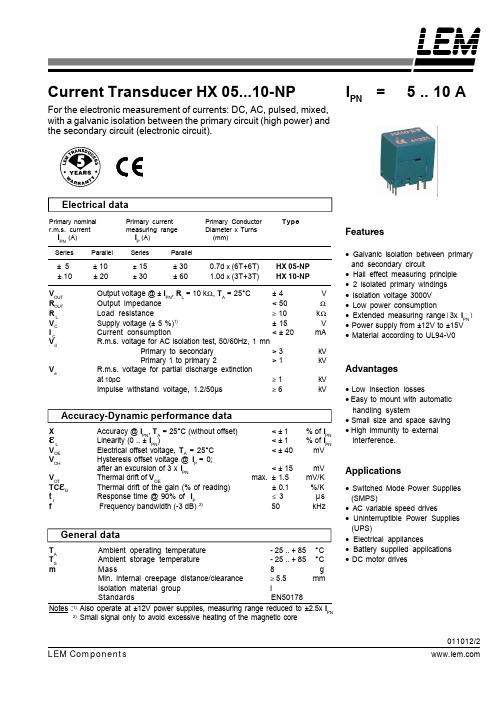
Advantages
kV kV
• Low insection losses • Easy to mount with automatic • Small size and space saving • High immunity to external
interference. handling system
• Hall effect measuring principle • 2 isolated primary windings • Isolation voltage 3000V • Low power consumption • Extended measuring range(3x IPN) • Power supply from ±12V to ±15V • Material according to UL94-V0
<±1 <±1 < ± 40 < ± 15 max. ± 1.5 ± 0.1 ≤ 3 50
% of IPN % of IPN mV mV mV/K %/K µs kHz
Applications
• Switched Mode Power Supplies • AC variable speed drives • Uninterruptible Power Supplies • Electrical appliances • Battery supplied applications • DC motor drives
Features
• Galvanic isolation between primary
and secondary circuit
± 5 ± 10 VOUT ROUT RL VC IC Vd
HDSP-3353-GG000中文资料
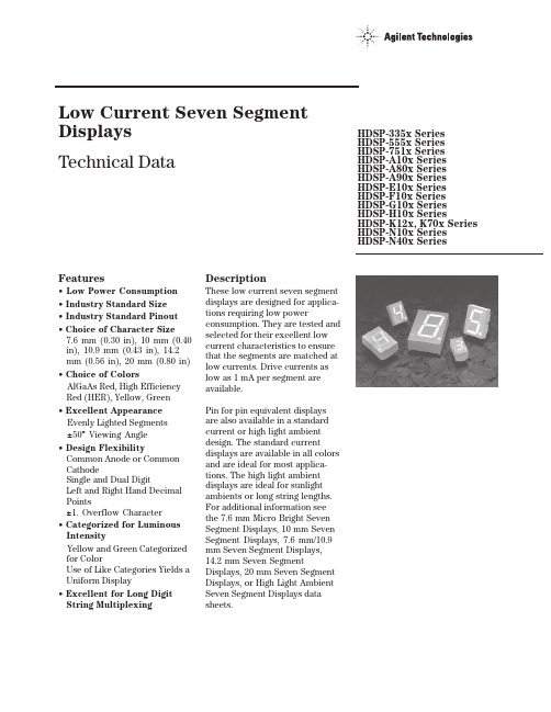
Features• Low Power Consumption • Industry Standard Size• Industry Standard Pinout • Choice of Character Size7.6 mm (0.30 in), 10 mm (0.40 in), 10.9 mm (0.43 in), 14.2 mm (0.56 in), 20 mm (0.80 in)• Choice of ColorsAlGaAs Red, High Efficiency Red (HER), Yellow, Green• Excellent Appearance Evenly Lighted Segments±50° Viewing Angle• Design FlexibilityCommon Anode or Common CathodeSingle and Dual DigitLeft and Right Hand Decimal Points±1. Overflow Character• Categorized for Luminous IntensityYellow and Green Categorized for ColorUse of Like Categories Yields a Uniform Display• Excellent for Long Digit String Multiplexing DescriptionThese low current seven segment displays are designed for applica-tions requiring low power consumption. They are tested and selected for their excellent low current characteristics to ensure that the segments are matched at low currents. Drive currents as low as 1 mA per segment are available.Pin for pin equivalent displays are also available in a standard current or high light ambient design. The standard current displays are available in all colors and are ideal for most applica-tions. The high light ambient displays are ideal for sunlight ambients or long string lengths. For additional information see the 7.6 mm Micro Bright Seven Segment Displays, 10 mm Seven Segment Displays, 7.6 mm/10.9 mm Seven Segment Displays, 14.2 mm Seven Segment Displays, 20 mm Seven Segment Displays, or High Light Ambient Seven Segment Displays data sheets.Low Current Seven SegmentDisplays Technical Data HDSP-335x SeriesHDSP-555x SeriesHDSP-751x SeriesHDSP-A10x Series HDSP-A80x Series HDSP-A90x Series HDSP-E10x Series HDSP-F10x Series HDSP-G10x Series HDSP-H10x Series HDSP-K12x, K70x Series HDSP-N10x SeriesHDSP-N40x SeriesDevicesAlGaAs HER Yellow Green Package HDSP-HDSP-HDSP-HDSP-Description Drawing A1017511A801A9017.6 mm Common Anode Right Hand Decimal A A1037513A803A9037.6 mm Common Cathode Right Hand Decimal B A1077517A807A9077.6 mm Common Anode ±1. Overflow C A1087518A808A9087.6 mm Common Cathode ±1. Overflow D F10110 mm Common Anode Right Hand Decimal E F10310 mm Common Cathode Right Hand Decimal F F10710 mm Common Anode ±1. Overflow G F10810 mm Common Cathode ±1. Overflow H G10110 mm Two Digit Common Anode Right Hand Decimal X G10310 mm Two Digit Common Cathode Right Hand Decimal Y E100335010.9 mm Common Anode Left Hand Decimal I E101335110.9 mm Common Anode Right Hand Decimal J E103335310.9 mm Common Cathode Right Hand Decimal K E106335610.9 mm Universal ±1. Overflow[1]L H101555114.2 mm Common Anode Right Hand Decimal M H103555314.2 mm Common Cathode Right Hand Decimal N H107555714.2 mm Common Anode ±1. Overflow O H108555814.2 mm Common Cathode ±1. Overflow P K121K70114.2 mm Two Digit Common Anode Right Hand Decimal R K123K70314.2 mm Two Digit Common Cathode Right Hand Decimal S N10020 mm Common Anode Left Hand Decimal Q N101N40120 mm Common Anode Right Hand Decimal T N103N40320 mm Common Cathode Right Hand Decimal U N10520 mm Common Cathode Left Hand Decimal V N106N40620 mm Universal ±1. Overflow[1]W Note:1. Universal pinout brings the anode and cathode of each segment’s LED out to separate pins. See internal diagrams L or W.Part Numbering System5082-x xx x-x x x xxHDSP-x xx x-x x x xxMechanical Options[1]00: No mechanical optionColor Bin Options[1,2]0: No color bin limitationMaximum Intensity Bin[1,2]0: No maximum intensity bin limitationMinimum Intensity Bin[1,2]0: No minimum intensity bin limitationDevice Configuration/Color[1]G: GreenDevice Specific Configuration[1]Refer to respective datasheetPackage[1]Refer to Respective datasheetNotes:1. For codes not listed in the figure above, please refer to the respective datasheet or contact your nearest Agilent representative fordetails.2. Bin options refer to shippable bins for a part-number. Color and Intensity Bins are typically restricted to 1 bin per tube (excep-tions may apply). Please refer to respective datasheet for specific bin limit information.Package DimensionsPackage Dimensions (cont.)Package Dimensions (cont.)*The Side View of package indicates Country of Origin.Package Dimensions (cont.)Package Dimensions (cont.)Package Dimensions (cont.)Internal Circuit DiagramInternal Circuit Diagram (cont.)Absolute Maximum RatingsAlGaAs Red - HDSP-HERA10X/E10X/H10X HDSP-751X/Yellow GreenK12X/N10X/N40X335X/555X/HDSP-A80X HDSP-A90X Description F10X, G10X Series K70X Series Series Series Units Average Power per Segment or DP375264mW Peak Forward Current per 45mA Segment or DPDC Forward Current per15[1]15[2]mA Segment or DPOperating Temperature Range-20 to +100-40 to +100°C Storage Temperature Range -55 to +100°C Reverse Voltage per Segment 3.0V or DPWave Soldering Temperature for 3Seconds (1.60 mm [0.063 in.] below 250°C seating body)Notes:1. Derate above 91°C at 0.53 mA/°C.2. Derate HER/Yellow above 80°C at 0.38 mA/°C and Green above 71°C at 0.31 mA/°C.Electrical/Optical Characteristics at T A = 25°CAlGaAs RedDeviceSeriesHDSP-Parameter Symbol Min.Typ.Max.Units Test Conditions315600I F = 1 mA A10x3600I F = 5 mA330650I F = 1 mAF10x, G10x3900I F = 5 mA390650I F = 1 mA E10x Luminous Intensity/Segment[1,2]I Vµcd(Digit Average)3900I F = 5 mA400700I F = 1 mAH10x, K12x4200I F = 5 mA270590I F = 1 mAN10x, N40x3500I F = 5 mA1.6I F = 1 mAForward Voltage/Segment or DP V F 1.7V I F = 5 mA1.82.2I F = 20 mA PkAll Devices Peak WavelengthλPEAK645nmDominant Wavelength[3]λd637nmReverse Voltage/Segment or DP[4]V R 3.015V I R = 100 µATemperature Coefficient of∆V F/°C-2 mV mV/°CV F/Segment or DPA10x255F10x, G10x320E10x340Thermal Resistance LED RθJ-PIN°C/W/SegH10x, K12x Junction-to-Pin400N10x, N40x430High Efficiency RedDeviceSeriesHDSP-Parameter Symbol Min.Typ.Max.Units Test Conditions160270I F = 2 mA 751x1050I F = 5 mA200300I F = 2 mA Luminous Intensity/Segment[1,2]I V mcd(Digit Average)1200I F = 5 mA335x, 555x,K70x270370I F = 2 mA1480I F = 5 mA1.6I F = 2 mAForward Voltage/Segment or DP V F 1.7V I F = 5 mA2.1 2.5I F = 20 mA Pk All Devices Peak WavelengthλPEAK635nmDominant Wavelength[3]λd626nmReverse Voltage/Segment or DP[4]V R 3.030V I R = 100 µATemperature Coefficient of∆V F/°C-2mV/°CV F/Segment or DP751x200335x Thermal Resistance LED RθJ-PIN280°C/WJunction-to-Pin555x, K70x345YellowDeviceSeriesHDSP-Parameter Symbol Min.Typ.Max.Units Test Conditions Luminous Intensity/Segment[1,2]250420I F = 4 mA(Digit Average)I V mcd1300I F = 10 mA1.7I F = 4 mAForward Voltage/Segment or DP V F 1.8V I F = 5 mA A80x2.1 2.5I F = 20 mA PkPeak WavelengthλPEAK583nmDominant Wavelength[3,5]λd581.5585592.5nmReverse Voltage/Segment or DP[4]V R 3.030V I R = 100 µATemperature Coefficient of∆V F/°C-2mV/°CV F/Segment or DPThermal Resistance LED RθJ-PIN200°C/WJunction-to-PinGreenDeviceSeriesHDSP-Parameter Symbol Min.Typ.Max.Units Test Conditions Luminous Intensity/Segment[1,2]250475I F = 4 mA(Digit Average)I V mcd1500I F = 10 mA1.9I F = 4 mAForward Voltage/Segment or DP V F 2.0V I F = 10 mA A90x2.1 2.5I F = 20 mA PkPeak WavelengthλPEAK566nmDominant Wavelength[3,5]λd571577nmReverse Voltage/Segment or DP[4]V R 3.030V I R = 100 µATemperature Coefficient of∆V F/°C-2mV/°CV F/Segment or DPThermal Resistance LED RθJ-PIN200°C/WJunction-to-PinNotes:1. Device case temperature is 25°C prior to the intensity measurement.2. The digits are categorized for luminous intensity. The intensity category is designated by a letter on the side of the package.3. The dominant wavelength, λd, is derived from the CIE chromaticity diagram and is the single wavelength which defines the color of thedevice.4. Typical specification for reference only. Do not exceed absolute maximum ratings.5. The yellow (HDSP-A800) and Green (HDSP-A900) displays are categorized for dominant wavelength. The category is designated by anumber adjacent to the luminous intensity category letter.Figure 1. Maximum AllowableAverage or DC Current vs. Ambient Temperature.Figure 2. Forward Current vs.Forward Voltage.AlGaAs RedFigure 4. Relative Efficiency (Luminous Intensity per UnitCurrent) vs. Peak Current.Figure 3. Relative Luminous Intensity vs. DC Forward Current.Figure 5. Maximum Allowable Average or DC Current vs. Ambient Temperature.Figure 6. Forward Current vs. Forward Voltage.HER, Yellow, GreenFigure 7. Relative Luminous Intensityvs. DC Forward Current.Figure 8. Relative Efficiency(Luminous Intensity per UnitCurrent) vs. Peak Current.Intensity Bin Limits (mcd)AlGaAs RedHDSP-A10xIV Bin Category Min.Max.E0.3150.520F0.4280.759G0.621 1.16H0.945 1.71I 1.40 2.56J 2.10 3.84K 3.14 5.75L 4.708.55HDSP-E10x/F10x/G10xIV Bin Category Min.Max.D0.3910.650E0.5320.923F0.755 1.39G 1.13 2.08H 1.70 3.14HDSP-H10x/K12xIV Bin Category Min.Max.C0.4150.690D0.5650.990E0.810 1.50F 1.20 2.20G 1.80 3.30H 2.73 5.00I 4.097.50HDSP-N10xIV Bin Category Min.Max.A0.2700.400B0.3250.500C0.4150.690D0.5650.990E0.810 1.50F 1.20 2.20G 1.80 3.30H 2.73 5.00I 4.097.50Intensity Bin Limits (mcd), continued HERHDSP-751xIV Bin Category Min.Max.B0.1600.240C0.2000.300D0.2500.385E0.3150.520F0.4280.759G0.621 1.16HDSP-751xIV Bin Category Min.Max.B0.2400.366C0.3000.477D0.3910.650E0.5320.923F0.755 1.39G 1.13 2.08H 1.70 3.14HDSP-555x/K70xIV Bin Category Min.Max.A0.2700.400B0.3250.500C0.4150.690D0.5650.990E0.810 1.50F 1.20 2.20G 1.80 3.30H 2.73 5.00I 4.097.50Intensity Bin Limits (mcd), continued YellowHDSP-A80xIV Bin Category Min.Max.D0.2500.385E0.3150.520F0.4250.760G0.625 1.14H0.940 1.70I 1.40 2.56J 2.10 3.84K 3.14 5.76L 4.718.64M7.0713.00N10.6019.40O15.9029.20P23.9043.80Q35.8065.60GreenHDSP-A90xIV Bin Category Min.Max.E0.3150.520F0.4250.760G0.625 1.14H0.940 1.70I 1.40 2.56J 2.10 3.84K 3.14 5.76L 4.718.64M7.0713.00N10.6019.40O15.9029.20P23.9043.80Q35.8065.60Electrical/OpticalFor more information on electrical/optical characteristics, please see Application Note 1005.Contrast Enhancement For information on contrast enhancement, please see Application Note 1015.Soldering/Cleaning Cleaning agents from the ketone family (acetone, methyl ethyl ketone, etc.) and from the chorinated hydrocarbon family (methylene chloride, trichloro-ethylene, carbon tetrachloride, etc.) are not recommended for cleaning LED parts. All of these various solvents attack or dissolve the encapsulating epoxies used to form the package of plastic LED parts.For information on soldering LEDs, please refer to Application Note 1027.Note:All categories are established for classification of products. Productsmay not be available in all categories. Please contact your localAgilent representatives for further clarification/information.Color Categories/semiconductorsFor product information and a complete list ofdistributors, please go to our web site.For technical assistance call:Americas/Canada: +1 (800) 235-0312 or(916) 788 6763Europe: +49 (0) 6441 92460China: 10800 650 0017Hong Kong: (+65) 6271 2451India, Australia, New Zealand: (+65) 6271 2394Japan: (+81 3) 3335-8152(Domestic/International), or0120-61-1280(Domestic Only)Korea: (+65) 6271 2194Malaysia, Singapore: (+65) 6271 2054Taiwan: (+65) 6271 2654Data subject to change.Copyright © 2005 Agilent Technologies, Inc.Obsoletes 5988-8412ENJanuary 19, 20055989-0080EN。
LM301AHNOPB,LM101AHNOPB,LM301ANNOPB,LM201AH,LM101AJ, 规格书,Datasheet 资料

LM101A,LM201A,LM301ALM101A/LM201A/LM301A Operational AmplifiersLiterature Number: SNOSBS0C 芯天下--/LM101A/LM201A/LM301A Operational AmplifiersGeneral DescriptionThe LM101A series are general purpose operational ampli-fiers which feature improved performance over industry stan-dards like the LM709.Advanced processing techniques make possible an order of magnitude reduction in input currents,and a redesign of the biasing circuitry reduces the temperature drift of input current.Improved specifications include:•Offset voltage 3mV maximum over temperature (LM101A/LM201A)•Input current 100nA maximum over temperature (LM101A/LM201A)•Offset current 20nA maximum over temperature (LM101A/LM201A)•Guaranteed drift characteristics•Offsets guaranteed over entire common mode and sup-ply voltage ranges•Slew rate of 10V/µs as a summing amplifierThis amplifier offers many features which make its appli-cation nearly foolproof:overload protection on the inputand output,no latch-up when the common mode range is exceeded,and freedom from oscillations and compensa-tion with a single 30pF capacitor.It has advantages over internally compensated amplifiers in that the frequency compensation can be tailored to the particular applica-tion.For example,in low frequency circuits it can be overcompensated for increased stability margin.Or the compensation can be optimized to give more than a factor of ten improvement in high frequency performance for most applications.In addition,the device provides better accuracy and lower noise in high impedance circuitry.The low input currents also make it particularly well suited for long interval integrators or timers,sample and hold circuits and low frequency waveform generators.Further,replac-ing circuits where matched transistor pairs buffer the inputs of conventional IC op amps,it can give lower offset voltage and a drift at a lower cost.The LM101A is guaranteed over a temperature range of −55˚C to +125˚C,the LM201A from −25˚C to +85˚C,and the LM301A from 0˚C to +70˚C.Fast AC/DC Converter00775233Note 1:Feedforward compensation can be used to make a fast full wave rectifier without a filter.August 2000LM101A/LM201A/LM301A Operational Amplifiers©2004National Semiconductor Corporation Absolute Maximum Ratings (Note 2)If Military/Aerospace specified devices are required,please contact the National Semiconductor Sales Office/Distributors for availability and specifications.LM101A/LM201ALM301ASupply Voltage±22V ±18V Differential Input Voltage ±30V ±30V Input Voltage (Note 3)±15V±15VOutput Short Circuit Duration (Note 4)ContinuousContinuous Operating Ambient Temp.Range −55˚C to +125˚C (LM101A)0˚C to +70˚C−25˚C to +85˚C (LM201A)T J Max H-Package 150˚C 100˚C N-Package 150˚C 100˚C J-Package150˚C100˚C Power Dissipation at T A =25˚C H-Package (Still Air)500mW 300mW (400LF/Min Air Flow)1200mW 700mW N-Package 900mW 500mW J-Package1000mW 650mW Thermal Resistance (Typical)θjAH-Package (Still Air)165˚C/W 165˚C/W (400LF/Min Air Flow)67˚C/W 67˚C/W N Package 135˚C/W 135˚C/W J-Package 110˚C/W 110˚CmW (Typical)θjCH-Package25˚C/W 25˚C/W Storage Temperature Range−65˚C to +150˚C−65˚C to +150˚CLead Temperature (Soldering,10sec.)Metal Can or Ceramic 300˚C 300˚C Plastic260˚C 260˚C ESD Tolerance (Note 7)2000V 2000VElectrical Characteristics (Note 5)T A =T JParameterConditionsLM101A/LM201A LM301A UnitsMinTyp Max Min Typ Max Input Offset Voltage T A =25˚C,R S ≤50k Ω0.7 2.0 2.07.5mV Input Offset Current T A =25˚C 1.510 3.050nA Input Bias Current T A =25˚C 307570250nA Input Resistance T A =25˚C 1.54.00.52.0M ΩSupply CurrentT A =25˚CV S =±20V 1.83.0mA V S =±15V1.8 3.0mA Large Signal Voltage Gain T A =25˚C,V S =±15V 5016025160V/mV V OUT =±10V,R L ≥2k ΩInput Offset VoltageR S ≤50k Ω 3.010mV Average Temperature Coefficient R S ≤50k Ω3.0156.030µV/˚Cof Input Offset Voltage Input Offset Current2070nA Average Temperature Coefficient 25˚C ≤T A ≤T MAX 0.010.10.010.3nA/˚C of Input Offset Current T MIN ≤T A ≤25˚C0.020.20.020.6nA/˚C Input Bias Current0.10.3µAL M 101A /L M 201A /L M 301A 2Electrical Characteristics(Note5)(Continued)T A=T JParameter Conditions LM101A/LM201A LM301A UnitsMin Typ Max Min Typ Max Supply Current T A=T MAX,V S=±20V 1.2 2.5mA Large Signal Voltage Gain V S=±15V,V OUT=±10V2515V/mVR L≥2kOutput Voltage Swing V S=±15V R L=10kΩ±12±14±12±14VR L=2kΩ±10±13±10±13V Input Voltage Range V S=±20V±15VV S=±15V+15,−13±12+15,−13V Common-Mode Rejection Ratio R S≤50kΩ80967090dB Supply Voltage Rejection Ratio R S≤50kΩ80967096dBNote2:Absolute Maximum Ratings indicate limits beyond which damage to the device may occur.Operating ratings indicate for which the device is functional,but do no guarantee specific performance limits.Electrical Characteristics state DC and AC electrical specifications under particular test conditions which guarantee specific limits.This assumes that the device is within the Operating Ratings.Specifications are not guaranteed for parameters where no limit is given,however,the typical value is a good indication of device performance.Note3:For supply voltages less than±15V,the absolute maximum input voltage is equal to the supply voltage.Note4:Continuous short circuit is allowed for case temperatures to125˚C and ambient temperatures to75˚C for LM101A/LM201A,and70˚C and55˚C respectively for LM301A.Note5:Unless otherwise specified,these specifications apply for C1=30pF,±5V≤V S≤±20V and−55˚C≤T A≤+125˚C(LM101A),±5V≤V S≤±20V and−25˚C ≤T A≤+85˚C(LM201A),±5V≤V S≤±15V and0˚C≤T A≤+70˚C(LM301A).Note6:Refer to RETS101AX for LM101A military specifications and RETS101X for LM101military specifications.Note7:Human body model,100pF discharged through1.5kΩ.Typical Performance CharacteristicsLM101A/LM201AInput Voltage Range Output Swing0077524100775242LM101A/LM201A/LM301A3Typical Performance CharacteristicsLM101A/LM201A (Continued)Voltage Gain00775243Guaranteed Performance CharacteristicsLM301AInput Voltage RangeOutput Swing0077524400775245Voltage Gain00775246L M 101A /L M 201A /L M 301A 4Typical Performance CharacteristicsSupply CurrentVoltage Gain0077524700775248Maximum Power DissipationInput Current,LM101A/LM201A/LM301A0077524900775250Current Limiting Input Noise Voltage0077525100775252LM101A/LM201A/LM301A5Typical Performance Characteristics(Continued)Input Noise CurrentCommon Mode Rejection0077525300775254Power Supply RejectionClosed Loop OutputImpedance0077525500775256L M 101A /L M 201A /L M 301A 6Typical Performance Characteristics for Various Compensation Circuits(Note9)Single Pole Compensation Two Pole Compensation00775208C S=30pF00775212C S=30pFC2=10C1Feedforward CompensationOpen Loop FrequencyResponse00775216f o=3MHz00775209Open Loop FrequencyResponseOpen Loop FrequencyResponse0077521300775217LM101A/LM201A/LM301A7Typical Performance Characteristics for Various Compensation Circuits(Note 9)(Continued)Large Signal FrequencyResponseLarge Signal FrequencyResponse0077521000775214Large Signal FrequencyResponse Voltage Follower PulseResponse0077521800775211Voltage Follower PulseResponseInverter Pulse Response0077521500775219L M 101A /L M 201A /L M 301A 8Typical Applications(Note9)Variable Capacitance Multiplier00775220Simulated Inductor00775221L.R1R2C1R S=R2R P=R1Fast Inverting Amplifierwith High Input Impedance00775222Inverting Amplifierwith Balancing Circuit00775223†May be zero or equal to parallel combination of R1and R2for minimumoffset.Sine Wave Oscillator00775224f o=10kHzIntegrator with Bias Current Compensation00775225*Adjust for zero integrator drift.Current drift typically0.1nA/˚C over−55˚Cto+125˚C temperature range.LM101A/LM201A/LM301A9Application Hints (Note 9)Protecting Against GrossFault Conditions00775226*Protects input †Protects output‡Protects output —not needed when R4is used.Compensating for Stray Input Capacitancesor Large Feedback Resistor00775227Isolating Large Capacitive Loads00775228Although the LM101A is designed for trouble free operation,experience has indicated that it is wise to observe certainprecautions given below to protect the devices from abnor-mal operating conditions.It might be pointed out that theL M 101A /L M 201A /L M 301A10advice given here is applicable to practically any IC op amp, although the exact reason why may differ with different de-vices.When driving either input from a low-impedance source,a limiting resistor should be placed in series with the input lead to limit the peak instantaneous output current of the source to something less than100mA.This is especially important when the inputs go outside a piece of equipment where they could accidentally be connected to high voltage sources. Large capacitors on the input(greater than0.1µF)should be treated as a low source impedance and isolated with a resistor.Low impedance sources do not cause a problem unless their output voltage exceeds the supply voltage.How-ever,the supplies go to zero when they are turned off,so the isolation is usually needed.The output circuitry is protected against damage from shorts to ground.However,when the amplifier output is connected to a test point,it should be isolated by a limiting resistor,as test points frequently get shorted to bad places.Further, when the amplifer drives a load external to the equipment,it is also advisable to use some sort of limiting resistance to preclude mishaps.Precautions should be taken to insure that the power sup-plies for the integrated circuit never become reversed—even under transient conditions.With reverse voltages greater than1V,the IC will conduct excessive cur-rent,fusing internal aluminum interconnects.If there is a possibility of this happening,clamp diodes with a high peak current rating should be installed on the supply lines.Rever-sal of the voltage between V+and V−will always cause a problem,although reversals with respect to ground may also give difficulties in many circuits.The minimum values given for the frequency compensation capacitor are stable only for source resistances less than 10kΩ,stray capacitances on the summing junction less than 5pF and capacitive loads smaller than100pF.If any of these conditions are not met,it becomes necessary to over-compensate the amplifier with a larger compensation capaci-tor.Alternately,lead capacitors can be used in the feedback network to negate the effect of stray capacitance and large feedback resistors or an RC network can be added to isolate capacitive loads.Although the LM101A is relatively unaffected by supply by-passing,this cannot be ignored altogether.Generally it is necessary to bypass the supplies to ground at least once on every circuit card,and more bypass points may be required if more than five amplifiers are used.When feed-forward compensation is employed,however,it is advisable to by-pass the supply leads of each amplifier with low inductance capacitors because of the higher frequencies involved.Typical Applications(Note9)Standard Compensation andOffset Balancing Circuit00775229Fast Voltage Follower00775231Power Bandwidth:15kHzSlew Rate:1V/µsFast Summing Amplifier00775230 Power Bandwidth:250kHzSmall Signal Bandwiidth:3.5MHzSlew Rate:10V/µsLM101A/LM201A/LM301A11Typical Applications (Note 9)(Continued)Bilateral Current Source00775232R3=R4+R5R1=R2Fast AC/DC Converter (Note 8)00775233Note 8:Feedforward compensation can be used to make a fast full wave rectifier without a filter.L M 101A /L M 201A /L M 301A 12Typical Applications (Note 9)(Continued)Instrumentation Amplifier00775234R1=R4;R2=R3*,†Matching determines CMRR.Integrator with Bias Current Compensation00775235*Adjust for zero integrator drift.Current drift typically 0.1nA/˚C over 0˚C to +70˚C temperature range.Voltage Comparator for Driving RTL Logic or HighCurrent Driver00775237LM101A/LM201A/LM301A13Typical Applications (Note 9)(Continued)Low Frequency Square Wave Generator00775236Low Drift Sample and Hold00775238*Polycarbonate-dielectric capacitorVoltage Comparator for Driving DTL or TTL Integrated Circuits00775239L M 101A /L M 201A /L M 301A 14Schematic(Note9)00775201Note9:Pin connections shown are for8-pin packages.Connection Diagrams(Top View)Dual-In-Line Package00775204Order Number LM101AJ,LM101J/883(Note10),LM201AN or LM301ANSee NS Package Number J08A or N08ECeramic Flatpack Package00775240Order Number LM101AW/883or LM101W/883See NS Package Number W10ALM101A/LM201A/LM301A15Connection Diagrams(TopView)(Continued)Metal Can Package00775202Note:Pin 4connected to case.Order Number LM101AH,LM101AH/883(Note 10),LM201AH or LM301AHSee NS Package Number H08CDual-In-Line Package00775203Order Number LM101AJ-14/883(Note 10)See NS Package Number J14ANote 10:Available per JM38510/10103.L M 101A /L M 201A /L M 301A 16LM101A/LM201A/LM301A Physical Dimensions inches(millimeters)unless otherwise noted ArrayMetal Can Package(H)Order Number LM101AH,LM101AH/883LM201AH or LM301AHNS Package Number H08C17Physical Dimensionsinches (millimeters)unless otherwise noted (Continued)Ceramic Dual-In-Line Package (J)Order Number LM101J/883or LM101AJNS Package Number J08ACeramic Dual-In-Line Package (J)Order Number LM101AJ-14/883NS Package Number J14AL M 101A /L M 201A /L M 301A 18Physical Dimensionsinches (millimeters)unless otherwise noted (Continued)Molded Dual-In-Line Package (N)Order Number LM201AN or LM301ANNS Package Number N08ECeramic Flatpack Package (W)Order Number LM101AW/883or LM101W/883NS Package Number W10ALM101A/LM201A/LM301A19NotesLIFE SUPPORT POLICYNATIONAL’S PRODUCTS ARE NOT AUTHORIZED FOR USE AS CRITICAL COMPONENTS IN LIFE SUPPORT DEVICES OR SYSTEMS WITHOUT THE EXPRESS WRITTEN APPROVAL OF THE PRESIDENT AND GENERAL COUNSEL OF NATIONAL SEMICONDUCTOR CORPORATION.As used herein:1.Life support devices or systems are devices or systems which,(a)are intended for surgical implant into the body,or (b)support or sustain life,and whose failure to perform when properly used in accordance with instructions for use provided in the labeling,can be reasonably expected to result in a significant injury to the user. 2.A critical component is any component of a life support device or system whose failure to perform can be reasonably expected to cause the failure of the life support device or system,or to affect its safety or effectiveness.BANNED SUBSTANCE COMPLIANCENational Semiconductor certifies that the products and packing materials meet the provisions of the Customer Products Stewardship Specification (CSP-9-111C2)and the Banned Substances and Materials of Interest Specification (CSP-9-111S2)and contain no ‘‘Banned Substances’’as defined in CSP-9-111S2.National Semiconductor Americas Customer Support CenterEmail:new.feedback@ Tel:1-800-272-9959National SemiconductorEurope Customer Support CenterFax:+49(0)180-5308586Email:europe.support@Deutsch Tel:+49(0)6995086208English Tel:+44(0)8702402171Français Tel:+33(0)141918790National Semiconductor Asia Pacific Customer Support CenterEmail:ap.support@National SemiconductorJapan Customer Support Center Fax:81-3-5639-7507Email:jpn.feedback@ Tel:81-3-5639-7560L M 101A /L M 201A /L M 301A O p e r a t i o n a l A m p l i f i e r sNational does not assume any responsibility for use of any circuitry described,no circuit patent licenses are implied and National reserves the right at any time without notice to change said circuitry and specifications.IMPORTANT NOTICETexas Instruments Incorporated and its subsidiaries(TI)reserve the right to make corrections,modifications,enhancements,improvements, and other changes to its products and services at any time and to discontinue any product or service without notice.Customers should obtain the latest relevant information before placing orders and should verify that such information is current and complete.All products are sold subject to TI’s terms and conditions of sale supplied at the time of order acknowledgment.TI warrants performance of its hardware products to the specifications applicable at the time of sale in accordance with TI’s standard warranty.Testing and other quality control techniques are used to the extent TI deems necessary to support this warranty.Except where mandated by government requirements,testing of all parameters of each product is not necessarily performed.TI assumes no liability for applications assistance or customer product design.Customers are responsible for their products and applications using TI components.To minimize the risks associated with customer products and applications,customers should provide adequate design and operating safeguards.TI does not warrant or represent that any license,either express or implied,is granted under any TI patent right,copyright,mask work right, or other TI intellectual property right relating to any combination,machine,or process in which TI products or services are rmation published by TI regarding third-party products or services does not constitute a license from TI to use such products or services or a warranty or endorsement e of such information may require a license from a third party under the patents or other intellectual property of the third party,or a license from TI under the patents or other intellectual property of TI.Reproduction of TI information in TI data books or data sheets is permissible only if reproduction is without alteration and is accompanied by all associated warranties,conditions,limitations,and notices.Reproduction of this information with alteration is an unfair and deceptive business practice.TI is not responsible or liable for such altered rmation of third parties may be subject to additional restrictions.Resale of TI products or services with statements different from or beyond the parameters stated by TI for that product or service voids all express and any implied warranties for the associated TI product or service and is an unfair and deceptive business practice.TI is not responsible or liable for any such statements.TI products are not authorized for use in safety-critical applications(such as life support)where a failure of the TI product would reasonably be expected to cause severe personal injury or death,unless officers of the parties have executed an agreement specifically governing such use.Buyers represent that they have all necessary expertise in the safety and regulatory ramifications of their applications,and acknowledge and agree that they are solely responsible for all legal,regulatory and safety-related requirements concerning their products and any use of TI products in such safety-critical applications,notwithstanding any applications-related information or support that may be provided by TI.Further,Buyers must fully indemnify TI and its representatives against any damages arising out of the use of TI products in such safety-critical applications.TI products are neither designed nor intended for use in military/aerospace applications or environments unless the TI products are specifically designated by TI as military-grade or"enhanced plastic."Only products designated by TI as military-grade meet military specifications.Buyers acknowledge and agree that any such use of TI products which TI has not designated as military-grade is solely at the Buyer's risk,and that they are solely responsible for compliance with all legal and regulatory requirements in connection with such use. TI products are neither designed nor intended for use in automotive applications or environments unless the specific TI products are designated by TI as compliant with ISO/TS16949requirements.Buyers acknowledge and agree that,if they use any non-designated products in automotive applications,TI will not be responsible for any failure to meet such requirements.Following are URLs where you can obtain information on other Texas Instruments products and application solutions:Products ApplicationsAudio /audio Communications and Telecom /communicationsAmplifiers Computers and Peripherals /computersData Converters Consumer Electronics /consumer-appsDLP®Products Energy and Lighting /energyDSP Industrial /industrialClocks and Timers /clocks Medical /medicalInterface Security /securityLogic Space,Avionics and Defense /space-avionics-defense Power Mgmt Transportation and Automotive /automotiveMicrocontrollers Video and Imaging /videoRFID OMAP Mobile Processors /omapWireless Connectivity /wirelessconnectivityTI E2E Community Home Page Mailing Address:Texas Instruments,Post Office Box655303,Dallas,Texas75265Copyright©2011,Texas Instruments Incorporated。
HDB-CTH1资料
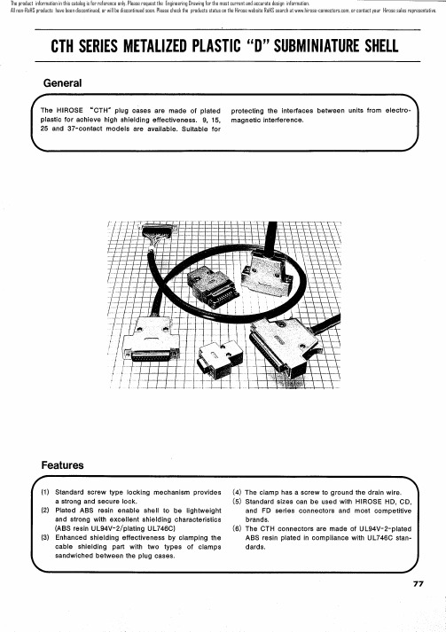
元器件交易网
The product information in this catalog is for reference only. Please request the Engineering Drawing for the most current and accurate design information. All non-RoHS products have been discontinued, or will be discontinued soon. Please check the products status on the Hirose website RoHS search at , or contact your Hirose sales representative.
元rmation in this catalog is for reference only. Please request the Engineering Drawing for the most current and accurate design information. All non-RoHS products have been discontinued, or will be discontinued soon. Please check the products status on the Hirose website RoHS search at , or contact your Hirose sales representative.
元器件交易网
The product information in this catalog is for reference only. Please request the Engineering Drawing for the most current and accurate design information. All non-RoHS products have been discontinued, or will be discontinued soon. Please check the products status on the Hirose website RoHS search at , or contact your Hirose sales representative.
HT101
GMPT Materials Engineering Group
9
Heat Treating 101 & CQI-9
Heat Treating of Metallic Materials/金属材料热处理
Principal of heat treating/热处理基本原理: During heating: Formation of Austenite/加热阶段:奧氏体形成 Austenite will be formed from original microstructure of ferrite and pearlite or tempered martensite. /奧氏体由铁素体, 珠光体或回火马氏体转变而成 During cooling: Decomposition of Austenite: CCT diagram /冷却阶段:奧氏体分解-连续冷却转变曲线
GMPT Materials Engineering Group 6
Crystal Structure of phase/晶体结构 Bcc/体心立方晶体 Bcc/体心立方晶体 Fcc/面心立方晶体 Complex orthorhombic / 斜方晶体 Hexagonal /六边形
bct
bct
Heat Treating 101 & CQI-9
3.
CQI-9 (Heat Treat System Assessment)/热 处理系统评估 • What is CQI-9/CQI-9内容 Why is CQI-9 needed/为什么需要CQI-9 • What are CQI-9 requirements/要求 • What heat treatment processes are covered/所涉及的热处理工艺 • What approach should be used in implementing CQI-9/CQI-9实施方法
AH101_温湿度记录仪

温湿度记录仪AH101 产品手册更多详情请登陆: 一、产品概述:该数据记录仪主要用于仓库存储和运输过程中的食品、医药、化工等产品的温湿度记录,特别是广泛应用于各种仓储、物流冷链,如冷藏集装箱、冷藏车、冷藏包装、冷库、实验室等。
实物图尺寸图(单位 mm)二、规格尺寸产品尺寸:95mm(长)×54mm(宽)×18mm(高)三、技术参数1、温度测量范围: -20℃~+60℃(外置探头-40 -80℃) 2、温度精度:-20℃~+40℃,±0.5℃ 3、温度单位:℃(摄氏度)/℉(华氏度)4、湿度测量范围:0~99.9%RH 湿度精度:±3%RH5、分辨率:温度0.1℃;湿度 0.1%RH6、灵敏度衰减值:温度:<0.1℃/年湿度:<1%RH/年 7、记录点数:32000 个点(最大)8、记录间隔:10s~18 小时可调节9、供电电压: USB 接口 5VDC10、电源:内置锂电池(可充电)11、电池寿命:正常情况下,如果记录间隔是 15 分钟,充一次电可使用一年;12、使用环境温度:-20℃~+60℃;在低温环境中,LCD 反应会相对变慢,但它对正常的测量和记录是没有影响的。
一旦温度恢复,显示屏就会正常显示。
四、记录仪配置说明:1、安装 AH101 温湿度数据管理软件。
将 AH101 通过 USB 数据线连接电脑,根据安装提示安装 USB 驱动程序。
2、打开温湿度数据管理软件,显示界面如图 1 所示,然后点击“仪器参数”,记录仪与PC 机相连接,自动上传之前设置的信息,如图 2 所示。
图 1 AH101 温湿度数据管理软件图 2 AH101 记录仪参数信息3、点击编辑,然后就可以修改相关参数,完成参数修改后,点击“参数更新”就将更新所有参数,并消除原有记录数据。
4、按下记录仪的按键并保持 3s,符号“ ”将会亮,表示当前开始记录;在软件里也可以设置延时开始记录功能,按下记录仪的按键并保持 3s,符号“ ”将会闪烁,表示当前延时记录功能已打开,当设置的延时时间到达时,记录仪表将自动开始记录,符号“”将一直点亮。
伊顿 EACF-101系列 防爆枪型摄像机 数据表
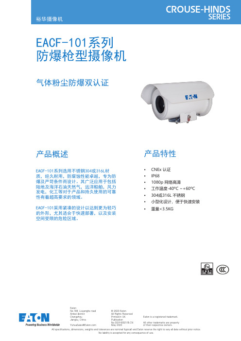
EatonNo.189, Liuyanghe road Xinbei district Changzhou Jiangsu, China********************产品概述EACF-101系列选用不锈钢304或316L材质,经久耐用,防腐蚀性能卓越,专为防爆及严苛条件而设计。
其广泛应用于包括陆地及海洋石油天然气,远洋船舶,风力发电,化工等对于产品和持久使用的可靠性有着超高要求的领域。
EACF-101采用紧凑的设计以达到更为轻巧的外形,尤其适合于快速部署,以及安装空间受限的危险区域。
产品特性• CNEx 认证• IP68• 1080p 网络高清• 工作温度-40ºC ~+60ºC • 304或316L 不锈钢• 小型化设计,便于快速安装•重量<3.5KGEACF-101系列防爆枪型摄像机气体粉尘防爆双认证All specifications, dimensions, weights and tolerances are nominal (typical) and Eaton reserve the right to vary all data without prior notice.No liability is accepted for any consequence of use.© 2023 EatonAll Rights Reserved Printed in UK PublicationNo.DSYH0021/ May 2023Eaton is a registered trademark.All other trademarks are property of their respective owners.表面处理不锈钢本色,可选抛光或表面喷涂工作温度-40ºC ~ +60ºC大气压强80~110KPa湿度≤95%RH (+25ºC)防护等级IP68(1.2m / 45min)净重<3.5KG毛重5KG线缆引入1x M25x1.5输入电压12VDC电流≤2A功率≤24W信号传输标准数字以太网/光纤传输/同轴以太网传输视频协议ONVIF Profile S & Profile T电动云台、半固定云台、固定支架、基座、立柱、塔架安装方式分辨率2304x1296 30fps镜头22倍光学变焦5.2-114.4mm F1.5-F3.8最小照度0.002lux(F1.5,AGC ON,彩色) 0.001lux(F1.5,AGC ON,黑白)视频流H.265、H.264、MJPEG特性BLC, AGS, AWB, WDR, DNR, OSD, 日夜自动/彩色/黑白 (IR-Cut filter removeable)协议标准TCP/IP, HTTP, DHCP, DNS, DDNS, RTP, RTSP, PPPoE, SMTP, NTP, UPnP, SNMP, FTP, 802.1x, QoS, HTTPS,IPv6智能功能移动侦测, 越界侦测, 区域入侵侦测, 离开区域侦测图像传感器逐行扫描 CMOS 1/2.8"分辨率2304x1296 30fps镜头33倍光学变焦4.5-148mm F1.5-F4.0最小照度0.002lux(F1.5,AGC ON,彩色) 0.001lux(F1.5,AGC ON,黑白)视频流H.265、H.264、MJPEG特性BLC, AGS, AWB, WDR, DNR, OSD, 日夜自动/彩色/黑白 (IR-Cut filter removeable)协议标准TCP/IP, HTTP, DHCP, DNS, DDNS, RTP, RTSP, PPPoE, SMTP, NTP, UPnP, SNMP, FTP, 802.1x, QoS,HTTPS, IPv6智能功能移动侦测, 越界侦测, 区域入侵侦测, 离开区域侦测图像传感器逐行扫描CMOS 1/ 2.8”分辨率2880x1620 30fps镜头22倍光学变焦5.2-114.4mm F1.5-F3.8最小照度0.002lux(F1.5,AGC ON,彩色) 0.001lux(F1.5,AGC ON,黑白)视频流H.265、H.264、MJPEG特性BLC, AGS, AWB, WDR, DNR, OSD, 日夜自动/彩色/黑白 (IR-Cut filter removeable)协议标准TCP/IP, HTTP, DHCP, DNS, DDNS, RTP, RTSP, PPPoE, SMTP, NTP, UPnP, SNMP, FTP, 802.1x, QoS,HTTPS, IPv6摄像机高清网络编码I热成像摄像机机芯无编码N护罩类型光学摄像机护罩编码V热成像镜头无编码 N雨刮无雨刮编码 N摄像机系统网络高清编码 I认证CNEx 非防爆编码 X N温度-40˚C ~ +60˚C编码2EACF-101 A C V N I U N N I 6 N D X 2 0 0材质类型不锈钢304不锈钢316L编码A B引出线长度无3米非铠装7米非铠装10米非铠装3米铠装7米铠装10米铠装特殊编码01231A 2A 3A S输入电压12VDC 编码6摄像机旋转不适用编码 N传输方式标准版编码0订购详情如下编码能帮助您找到合适的型号。
PH101_酸碱度分析仪说明书(中文)

操作说明书使用前注意事项(一)错误的接线将导致仪器故障及触电﹐请熟读操作说明书后再自行安装。
(二)背面接地点(E点)必须确实接好(如图说明书)。
(三)当电源是三相(3ψ)AC220V时﹐请注意火线﹐以避免干扰。
(四)Relay的接触点最大电流是﹕AC110V时为1.5A﹐AC220V时为3A﹐超过时必须外加耐大电流之继电器(Power relay)。
(五)控制器安装现场必须选择通风良好﹐避免阳光直射。
参考电器图如下﹕.R: Power RelayM: MagneticPH/A: Relay a contactR/A1, R/A2: Power Relay a contactM/A1, M/A2, M/A3: Magnetic a contact酸碱度及氧化还原分析仪操作说明书一.酸碱度及氧化还原分析仪介绍(PH/ORP Analyzer)HOTEC分析仪为国人自行研制设计之精密仪器﹐可适用于任何场合﹐采用较大型LCD液晶显示(0.8〞)可耐温至90℃不变黑。
型号归类如下﹕Hi/Lo式控制﹐Model: PH CONTROLLER PH-101ORP CONTROLLER ORP-101Hi Hi /Lo Lo式控制,Model: PH CONTROLLER PH-102ORP CONTROLLER ORP-102HOTEC分析仪使用的电极来自美国BJC公司﹐为目前欧美电极种类最多﹑质量最佳的工业电极﹐可适用于各种场合﹐如废水槽﹑发酵槽﹐本公司生产之控制器为高阻抗输入型﹐可适用任何厂牌工业用电极。
二.使用前安装程序﹕1.核对配件是否齐全。
2.安装组合电极。
3.安装控制器。
4.连接电极线﹑讯号线及传送器。
5.连接加药机﹑电磁阀。
6.确定操作范围接上电源。
7.校正使用标准液。
8.设定控制区。
三.规格Model pH/ORP-101 pH/ORP-102 Range PH: 0 to 14.00 pH, ORP: -1000mv to +1000mv Resolution 0.01pH, 1mVAccuracy 0.01pH±1 digit, 1mV±1 digitImpedance >1012ΩTemperature Compensation ATC probe or Manual Fixed Resistance Display 3 1/2 0.8〞LCDCurrent Output 4~20mA Max. load 1kΩCurrent Action Relay NO/OFFCurrent on Contact 220V AC Max. 3A/110V AC Max. 1.5A Control Limit Hi/Lo Hi Hi/Lo Lo Set Point 2 4Power 110V, 220V AC±12%, 50/60HzCut Out Dimension 135mm×135mm×182mm(H×W×D) Weights 1.45Kg 1.55Kg四.面板说明A. 型号HOTEC PH/ORP-101(TABLE1)TABLE1B. 型号﹕PH/ORP-101功能键说明﹕(1)﹝POWER﹞键﹕电源开关。
磁阻传感器电子罗盘及其在船舶导航中的应用

磁阻传感器电子罗盘及其在船舶导航中的应用肖文平 叶家伟(华南理工大学交通学院)摘 要 本文介绍了应用磁阻传感器的电子罗盘的电路设计和数据采集、航位推算导航的动态模型,将电子罗盘数据、船的速度信息和GPS数据进行信息融合以提高导航的精度。
最后探讨了低价位的电子罗盘与GPS组合导航技术在中小型船舶导航中的应用。
关键词 船舶导航 磁阻传感器 罗盘一 前 言目前,船舶导航主要采用GPS定位技术,GPS定位方式能够迅速、准确、全天候地提供导航、定位信息。
虽然美国政府宣布从2000年5月1日午夜开始不再人为故意降低GPS 公用信号的精度(即使用SA技术),可以使GPS定位比以前有高得多的精度,同时我们还要考虑美国恢复这一技术的风险。
GPS定位存在误差,主要误差源有:卫星时钟误差、星历误差、电离层的附加延时误差、对流层的附加延时误差、多路径误差等。
GPS天线受其他物体的遮挡、外界强信号源的干扰都会引起GPS的定位信息的中断,使定位精度大大降低。
船位推算(DeadReckoning)导航法是最基本的导航方法之一,这种方法的基本原理是利用航行的方向和距离传感器来推算瞬时位置。
将GPS导航定位系统与电子罗盘、速度信号组成的航位推算系统结合起来,可以很好地解决船舶航行短时间内丢失GPS卫星定位信号的问题。
电子罗盘是航位推算法的关键元器件之一,采用基于磁原理磁场传感器来测量相对地球磁北极航向角,误差不随时间积累,且体积小、可靠性高、响应速度快。
相比传统机械罗盘具有响应速度快、数据容易采集等特点。
鉴于大中型船舶导航技术较完善,本文探讨的低成本的电子罗盘与GPS组合数字导航技术以导航技术较差的中小型船舶作为对象,以期在中小型船舶替代传统技术并扩大导航技术应用范围(如水上智能交通技术)。
二 电子罗盘电路1 HMC1022简介HMC1022是Honeywell公司生产的智能弱磁传感器,是基于磁阻传感器的原理(参见图1),由长而薄的的镀膜合金(一种铁镍合金)薄膜制成磁阻敏感元件,采用标准的半导体工艺,将薄膜附着在硅片上,4个磁阻组成惠斯通电桥。
