CADMAN2011
CAD2011命令大全
下面是最新AutoCAD2011命令大全的M命令N命令O命令P命令Q命令,请大家阅读!M 命令MARKUP :打开标记集管理器。
MARKUPCLOSE :关闭标记集管理器。
MASSPROP :计算面域或三维实体的质量特性。
MATBROWSERCLOSE :关闭材质浏览器。
MATBROWSEROPEN :打开材质浏览器。
MATCHCELL :将选定表格单元的特性应用于其他表格单元。
MATCHPROP :将选定对象的特性应用于其他对象。
MATEDITORCLOSE :关闭材质编辑器。
MATEDITOROPEN :打开材质编辑器。
MATERIALASSIGN :使用CMATERIAL 系统变量中所定义的当前材质。
MATERIALATTACH :将材质与图层关联。
MATERIALMAP :显示材质贴图小控件,以调整面或对象上的贴图。
MATERIALS :打开材质浏览器。
MATERIALSCLOSE :关闭材质浏览器。
MEASURE :沿对象的长度或周长按测定间隔创建点对象或块。
MEASUREGEOM :测量选定对象或点序列的距离、半径、角度、面积和体积。
MENU :加载自定义文件。
MESH :创建三维网格图元对象,例如长方体、圆锥体、圆柱体、棱锥体、球体、楔体或圆环体。
MESHCAP :创建用于连接开放边的网格面。
MESHCOLLAPSE :合并选定网格面或边的顶点。
MESHCREASE :锐化选定网格子对象的边。
MESHEXTRUDE :将网格面延伸到三维空间。
MESHMERGE :将相邻面合并为单个面。
MESHOPTIONS :显示“网格镶嵌选项”对话框,此对话框用于控制将现有对象转换为网格对象时的默认设置。
MESHPRIMITIVEOPTIONS :显示“网格图元选项”对话框,此对话框用于设置图元网格对象的镶嵌默认值。
MESHREFINE :成倍增加选定网格对象或面中的面数。
MESHSMOOTH :将三维对象(例如多边形网格、曲面和实体)转换为网格对象。
CAD 2011安装详细步骤

Auto AutoCAD CAD 2011(64位\32位)安装位)安装激活激活激活详细步骤详细步骤有朋友急于知道激活过程,先上图,看懂了就不用看后面的了,看不懂请耐心看后面说明。
1双击文件夹中第二个安装程序,运行CAD 初步自解压2先择解压位置,可以选择默认的C\Autodesk\AutoCAD-2011-KEST_Win_64,也可以右击Browse 选择自己指定的解压位置。
注意:解压后的文件以及第一步中的安装包在最终安装后可以删除,以节约硬盘空间。
3解压,过程有点漫长,请耐心等待。
4.解压后它会自动开始安装。
如果出现如下情况请点击是(Y)如果没有开始自动安装要在刚才指定的,解压后的文件中找到STEUP,两击开始安装。
然后会出现以下界面:5.点击“安装产品”,输入序列号及密码用户信息可以随便输,然后选择“我已拥有我的产品信息”输入序列号输:356-72378422,666-69696969,667-98989898,400-45454545其中任意一项。
产品密钥输入001C1,225C1其中任意一项。
6.在选择要安装的产品后,可以使用系统的默认推荐设置开始下一步的安装。
当然也可以先选择自己要设置的产品,点“配置”开始设置“安装的位置”之类的配置。
之后点“安装”。
如下为安装中的画面7.打开Autocad2011程序。
系统会自动要求你产品许可证激活。
在断网条件下点“激活(A)”。
(有人说在激活前一定要断网,避免程序自动开启联机激活。
我是联网激活的。
)9、由于未联网,所以产品不会激活,会出现以下产品激活选项对话框。
选择“我具有Autodesd提供的激活码”。
然后产品申请号记录下来或选择后按组合键“ctrl+C”,将申请号复制下来用于下一步激活码的计算。
10、以管理员的身份打开注册机。
注意,一定要用管理员的身份打开。
11、在如下的窗口中先单击“Mem Patch”按键,你应该会看到出现“successfully patched”。
AutoCAD 2011中文版标准教程(第7版)课件第9章图形设计辅助工具
9.1.3 图形复制
❖ 执行上述命令后,系统打开“自定义”对话框的“工具选项板-所有选项 板”选项卡,如图所示。
9.2.4 向工具选项板添加内容
❖ 向工具选项板添加内容的具体步骤如下。 ❖ (1)将图形、块和图案填充从设计中心移到工具选项板上。 ❖ (2)使用“剪切”、“复制”和“粘贴”命令将一个工具选项板中的工
具移动或复制到另一个工具选项板中。
9.2.5 实例——绘制居室布置平面查询距离
❖ 【执行方式】 ❖ 命令行:DIST ❖ 菜单:“工具”→“查询”→“距离” ❖ 工具栏:“查询”→“距离” ❖ 【操作格式】 ❖ 命令:DIST↙ ❖ 指定第一点:↙(指定第一点) ❖ 指定第二点:↙(指定第二点) ❖ 距离 = 5.2699,XY 平面中的倾角 = 0, ❖ X 增量 = 5.2699, Y 增量 = 0.0000,
与 XY 平面的夹角 = 0 Z 增量 = 0.0000
9.3.2 查询对象状态
❖ 【执行方式】 ❖ 命令行:STATUS ❖ 菜单:“工具”→“查询”→“状态” ❖ 【操作格式】 ❖ 命令:STATUS↙ ❖ 选择对象:↙
内容要点
设计中心 工具选项板 对象查询
9.1设计中心
9.1.1 启动设计中心
❖ 【执行方式】 ❖ 命令行:ADCENTER ❖ 菜单:“工具”→“选项板”→“设计中心” ❖ 工具栏:“标准”→“设计中心” ❖ 快捷键:Ctrl+2 ❖ 【操作格式】 ❖ 命令:ADCENTER↙
9.1.2 插入图块
第9章图形设计辅助工具
对于一个项目或一个系统的图形设计而言,其复杂程度远远超过单个 图形的绘制。为了提高系统整体的图形设计效率,并有效地管理整个 系统的所有图形设计文件,AutoCAD 2011经过不断地探索和完善,推 出了大量的图形设计辅助工具,包括设计中心、工具选项板、CAD标 准管理器和图纸集管理器等工具。利用设计中心和工具选项板,用户 可以建立自己的个性化图库,也可以利用他人提供的强大资源快速准 确地进行图形设计,同时,利用CAD标准管理器和图纸集管理器,可 以有效地协同统一管理整个系统的图形文件。
AutoCAD 2011命令大全
AutoCAD 2011命令大全3D 命令●3D:在可以隐藏、着色或渲染的常见几何形状中创建三维多面网格对象。
●3DALIGN :在二维和三维空间中将对象与其他对象对齐。
●3DARRAY:以矩形或环形方式创建对象的三维矩阵。
●3DCLIP:启动交互式三维视图并打开“调整剪裁平面”窗口。
●3DCONFIG:设定影响三维显示性能的选项。
●3DCORBIT:在三维空间中连续旋转视图。
●3DDISTANCE:启动交互式三维视图并使对象显示得更近或更远。
●3DDWF:创建三维模型的三维 DWF 文件或三维 DWFx 文件,并将其显示在 DWF Viewer 中。
●3DEDITBAR:重塑 NURBS 曲面相切的形状,以及缩放和编辑 NURBS 曲面相切。
●3DFACE:在三维空间中创建三侧面或四侧面的曲面。
●3DFLY:交互式更改图形中的三维视图以创建在模型中飞行的外观。
●3DFORBIT:在三维空间中旋转视图而不约束回卷。
●3DMESH:创建自由形式的多边形网格。
●3DMOVE:在三维视图中,显示三维移动小控件以帮助在指定方向上按指定距离移动三维对象。
●3DORBIT:在三维空间中旋转视图,但仅限于水平动态观察和垂直动态观察。
●3DORBITCTR:在三维动态观察视图中设置旋转的中心。
●3DOSNAP:设定三维对象的对象捕捉模式。
●3DPAN:图形位于透视视图中时,启动交互式三维视图,并允许用户水平和垂直拖动视图。
●3DPOLY:创建三维多段线。
●3DPRINT:将三维模型发送到三维打印服务。
●3DROTATE:在三维视图中,显示三维旋转小控件以协助绕基点旋转三维对象。
●3DSCALE:在三维视图中,显示三维缩放小控件以协助调整三维对象的大小。
●3DSIN:输入 Autodesk 3ds MAX (3DS) 文件。
●3DSWIVEL:在拖动方向上更改视图的目标。
●:交互式更改图形中的三维视图以创建在模型中漫游的外观。
AutoCAD2011安装教程
安装步骤:
1.右击软件压缩包,选择解压到CAD2011软件安装包
2.打开CAD2011软件安装包
3.点击Setup
4.选择安装产品
5.勾选Design Revie后,点击下一步
6.选择我接受
7.姓氏随便输入,序列号输入:666-69696969,密钥输入:001C1
8.点击配置
9.选择单机许可
10.勾选Express后,更改软件安装路径(建议安装到除C盘以外的磁盘,我在D盘里面新建了一个文件夹CAD2011)
11.选择不包含service pack
12.点击配置完成
13.点击安装后,选择是
14.安装进行中(可能需要10分钟左右)
15.把查看前面的2个勾去掉后,点击完成
16.在电脑桌面上找到CAD软件图标后,双击打开。
17.点击激活后,选择我具有提供的激活码。
18.打开软件包里面的注册机
19.把申请号复制到注册机里面,先点击Mem Patch,再点击Generate后复制激活码,粘贴激活码后点击下一步即可。
提示:复制和粘贴的时候只能用快捷键“Ctrl+C”和“Ctrl+V”
20.点击完成
21.把启动时显示此对话框前面的勾去掉后,点击最右上方的关闭按钮。
22.选择不,谢谢。
点击确定。
23.安装完成。
计算机绘图——AutoCAD2011中文版第1-3章

1.3 AutoCAD命令
1.提示说明 1)选项中不带括号的提示为默认选项,此例中可直接指定一点或输 入比例因子(nX或nXP)。 2)要选择“[ ]”里的选项,首先应输入该选项的标识字符,如 “全部”选项的标识字符“A”,然后按系统提示输入相关内容。 3)“<>”内为默认值(系统的默认值,可重新输入或修改)或当前值。 4)“()”里的内容是AutoCAD命令选项的说明。
(3)菜单输入 1)下拉菜单输入 选中下拉菜单选项,输入AutoCAD命令。
1.3 AutoCAD命令
2)快捷菜单输入 用鼠标右键单击屏幕上不同的位置或不同的进程, 将弹出不同的快捷菜单,从中可以选择与当前操作相关的命令,如 图1-16所示。
图1-16 快捷菜单 a)选择某对象,但未执行命令时的绘图窗口快捷菜单 b)未选择对象、未执行命 令时的绘图窗口快捷菜单 c)执行某命令时的绘图窗口快捷菜单 d)命令窗口快捷菜单
1.2 AutoCAD 2011的工作界面
(1)应用程序按钮 应用程序按钮位于界面的左上角,单击该按钮, 系统弹出应用程序菜单,如图1-4所示。 (2)快速访问工具栏 AutoCAD 2011的快速访问工具栏位于应用程序 按钮的右侧,如图1-5所示。
图1-3 AutoCAD 2011的工作界面
1.2 AutoCAD 2011的工作界面
1.3 AutoCAD命令
1.4 数据的输入 1.5 AutoCAD的文件管理
Hale Waihona Puke 1.6 AutoCAD的帮助系统
AutoCAD 2011中文版实用教程第1章 AutoCAD 2011基础
AutoCAD 2011是美国Autodesk公司于2009年推出的最新版本,这 个版本与2009版的DWG文件及应用程序兼容,拥有很好的整合性。
在本章中,我们开始循序渐进地学习AutoCAD 2011绘图的有关基 本知识。了解如何设置图形的系统参数、样板图,熟悉建立新的图形文 件、打开已有文件的方法等。
和“打印”等几个最常用的工具。用户也可以单击本工具栏后面的下 拉按钮设置需要的常用工具。 2.交互信息工具栏 该工具栏包括“搜索”、“速博应用中心”、“通讯中心”、“收藏 夹”和“帮助”等几个常用的数据交互访问工具。
1.1.12 功能区
包括“常用”、“插入”、“注释”、“参数化”、“视图”、“管 理”和“输出”8个功能区,每个功能区集成了相关的操作工具,方便 了用户的使用。用户可以单击功能区选项后面的按钮控制功能的展开 与收缩。 打开或关闭功能区的操作方式如下: 命令行:RIBBON(或RIBBONCLOSE) 菜单:工具→选项板→功能区
1.2.3 坐标系图标
在绘图区域的左下角,有一个直线指向图标,称之为坐标系图标,表 示用户绘图时正使用的坐标系形式,如图所示。坐标系图标的作用是 为点的坐标确定一个参照系。详细情况将在1.5.4小节介绍。根据工作 需要,用户可以选择将其关闭。方法是选择菜单命令:视图→显示
→UCS图标→开,如图所示。
在有些图标的右下角带有一个小三角,按住鼠标左键会打开相应的工具栏, 按住鼠标左键,将光标移动到某一图标上然后松手,该图标就为当前图标。 单击当前图标,执行相应命令(如图所示)。
1.2.6 命令行窗口
命令行窗口是输入命令名和显示命令提示的区域,默认的命令行窗口 布置在绘图区下方,是若干文本行。
CADMAN TOUCH使用手册(2011)
目
录
说明 ....................................................................................................................................................2 简 介: .........................................................................................................................................4
一、常用信息: ........................................................................................................................5 系统: ........................................................................................................................................5 按钮: ........................................................................................................................................5 触摸屏 ........................................................................................................................................6 用户级别: ................................................................................................................................7 对触摸屏的数据进行备份:.....................................................................................................7 二. 启动和停止机床 .........................................................................................................................8 启动: ........................................................................................................................................8 关机: ........................................................................................................................................8 三.手动模式 ....................................................................................................................................9 主菜单: ....................................................................................................................................9 主菜单中的参数: ..................................................................................................................10 屏幕上工序列表中各参数含义:...........................................................................................14 四、编辑模式 ..................................................................................................................................28 主菜单 ......................................................................................................................................28 在主菜单中的其它参数:.......................................................................................................33 增加,删除程序: ........................................................................................................................34 新建程序: .................................................................................................................................34 五.自动生产模式: .........................................................................................................................35 主菜单: .....................................................................................................................................35 编辑页面: ..............................................................................................................................35 轴的页面: ..............................................................................................................................36 模拟仿真页面: ......................................................................................................................37
2011CAD教程

练习
文件: Exercise Dwgs\自定义库.dwg
使用AutoCAD Mechanical标准件库 使用AutoCAD Mechanical标准件库
标准件库内容总览
支持ANSI、BSI、AFNOR、DIN、GB、ISO和JIS 包括700,000多个标准零件和特征
特征 紧固件 轴用零件 弹簧 型材
配置和使用Power(增强) 配置和使用Power(增强)命令 Power
增强捕捉
增强捕捉实例
鼠标悬停 在对称线上
配置和使用Power(增强) 配置和使用Power(增强)命令 Power
增强标注
参考:增强标注.avi 线性标注
组
配置和使用Power(增强) 配置和使用Power(增强)命令 Power
内容
Mechanical总览 AutoCAD Mechanical总览 Mechanical用户界面 AutoCAD Mechanical用户界面 用户自定义模板设置
Mechanical总览 AutoCAD Mechanical总览
专业的绘图工具
增强标注 构造线 圆角和倒角
中心线
带中心线的孔
剖面线
用户自定义模板设置
自定义制图模板文件
默认存放位置
C:\Documents and Settings\user name\Local Settings\Application Data\Autodesk\AutoCAD Mechanical 2010\R17.2\chs\Template
步骤 按照公司标准
增强编辑
命令AMPOWEREDIT 双击对象
标准孔
配置和使用Power(增强) 配置和使用Power(增强)命令 Power
AutoCAD 2011 软件操作方法
AutoCAD 2011 软件操作方法详解制作人:邵朋辉指导老师:张培训班级:煤矿开采一班系部:矿业工程系备注:此次制作只为学习AutoCAD的学生提供参考和学习,为祖国培养更多的人才,建设国家。
此次制作不含任何商业活动及目的,如有疑问请与本人联系,QQ:510718705 。
参考资料视频:软件自学网。
详细列表:直线工具及坐标 (3)角度与直线的关系 (4)改变直线或标注线的颜色或线型 (7)椭圆及椭圆的两种绘法 (9)矩形工具及特性使用 (10)多边形工具使用 (10)结构线工具的使用 (11)多段线工具使用 (12)复制 (13)点及阵列 (14)缩放工具的使用 (15)拉伸及延伸工具的使用与技巧 (16)倒角和倒圆角 (16)环形阵列及布局的技巧 (17)矩形阵列及绘图技巧 (18)练习题集 (19)直线工具及坐标直线:L,单位默认为毫米,工程上用的都是毫米1:输入起点0,0输入缩写L,空格,然后输入0,0,空格,直线的起点就到了零点零处。
(x,y)2:画出规定长度的直线输入缩写L,空格,点先第一个点,然后选择方向,再输入长度,空格。
角度与直线的关系绘图工具栏消失:左侧的绘图等工具栏消失结局方法,如2图,在绘图软件右上册Stardard下边的空白处空间,AutoCAD,点绘图。
(1)(2)画角度线:1:画一条线,鼠标一定角度的移动,软件会自动捕捉一定的角度,当软件显示是四十五度(示例)时,点鼠标左键,出来的角度就是四十五度的线。
(比较麻烦)(3)2:快捷确定角度和方位正角(图三)直线后,输入@,20,37@(shift+2),20(直线长度),37(直线角度,输入<37)负角(图四)直线后,输入@,18,-30@(shift+2),18(直线长度),-30(直线角度,输入<-30)(四)另一种画负三十度直线的画法直线后,输入@,18,330@(shift+2),18(直线长度),330(直线角度,输入<330)图五练习题没有起点画出图六的练习题图六画法分析:,以0,0点为外围大正方形的起点(左下角点)画出外围的长方形,然后以0,0推算出另外两个长方形左下角的点,以此点为起点画出另外两个小的长方形,完成后,剪切或移动到其他地方。
AutoCAD 2011中文版实用教程第2章 基本绘图命令

直线类命令 圆类命令 平面图形命令 点命令
2.1.3 构造线
◆执行方式 命令行:XLINE 菜单:绘图→构造线 工具栏:绘图→构造线 ◆操作格式 命令: XLINE↙ 指定点或[水平(H)/垂直(V)/角度(A)/二等分(B)/偏移(O)]:(给出根点1) 指定通过点:(给定通过点2,绘制一条双向无限长直线) 指定通过点:(继续给点,继续绘制线,回车结束) ◆选项说明 (1)执行选项中有“指定点”、“水平”、“垂直”、“角度”、
块,后续操作与上节等分点类似。 (3)在等分点处,按当前点样式设置画出等分点。 (4)最后一个测量段的长度不一定等于指定分段长度。
在对象上指定一点作圆的第一条切线:(在7点附近选中C圆) 在对象上指定一点作圆的第二条切线:(在8点附近选中B圆) 指定圆的半径: <45.2769>:45↙ (绘制出D圆) 命令: _circle (选取下拉菜单“绘图/圆/相切、相切、相切”) 指定圆的圆心或 [三点(3P)/两点(2P)/切点、切点、半径(T)]: _3p 指定圆上的第一点: (打开状态栏上的“对象捕捉”按钮,关于
第2章 基本绘图命令
二维图形是指在二维平面空间绘制的图形,主要由一些基本 图形元素组成,如点、直线、圆弧、圆、椭圆、矩形、多边形 等几何元素。AutoCAD提供了大量的绘图工具,可以帮助用户 完成二维图形的绘制。本章主要介绍一些基本的二维绘图命令, 包括直线类命令、圆类命令、点命令、平面形命令、轨迹线与 区域填充、修订云线与徒手线、擦除对象等 。
面讲述) 于(点取P2点附近右上圆弧) 指定圆弧的第二点或 [圆心(C)/端点(E)]: E↙ 指定圆弧的端点: @40<252↙ 指定圆弧的圆心或 [角度(A)/方向(D)/半径(R)]: A↙ 指定包含角: 180↙
AutoCAD2011新功能-工程
AutoCAD2011新功能-工程AutoCAD2011新功能:一3D增强功能(一)曲面造型1 建立程序曲面和NURBS曲面AutoCAD 2011 引入了增強的曲面塑型功能,並加入了建立NURBS 曲面的功能,。
此類型的曲面具有控制頂點(CV),控制頂點可讓您以雕刻實體模型的相同方式「雕刻」物件。
NURBS 曲面以Bezier 曲線或平滑曲線為基礎,這使其成為建立曲線式物件 (例如汽車、船和吉他) 的理想工具。
2 编辑程序曲面和NURBS曲面由於NURBS 曲面具有控制頂點(CV),因此其可提供比舊式程序曲面更高程度的塑型功能。
另一方面,程序曲面具有關聯式塑型的優點。
在此範例中,在U 方向上加入了一列CV。
此動作變更了曲面的造型。
您也可以按一下並拖曳一個或多個 CV,來對物件進行重新塑型。
3 将几何图形投影至曲面與將影片投影至螢幕相似,您可以將曲線投影至程序曲面和NURBS 曲面。
此動作可讓您在曲面上建立修剪邊緣。
如這些插圖中所示,可從不同方向投影曲線:UCS、兩點和視圖。
4 使用关联曲面和约束與填充線和標註一樣,曲面也可以是關聯式曲面。
移動或修改曲面時,所有關聯曲面都會自動調整。
在此插圖中,船由四個曲面構成。
拉伸一側並對其進行重新塑型時,所有關聯曲面均會相應地進行調整。
可使用 SURFACEASSOCIATIVITY 系統變數來打開和關閉關聯性。
(二)网面造型1 修改面多種增強功能提供了用於修改網面面的其他工具。
例如,您可以選取相鄰網面面,並將其合併以建立單一面 (MESHMERGE)。
2 删除面与修复间隙可使用以下兩種方法之一移除網面面:選取面,然後按 Delete。
輸入 ERASE 並選取面。
這兩種方法都會在網面中產生間隙。
(三)实体造型1 倒圆角和实体您可以使用兩個新指令來倒角和圓角 3D 實體的邊緣:CHAMFEREDGEFILLETEDGE選取要修改的一條或多條邊緣。
然後,按一下並拖曳邊緣,以調整和預覽圓角或倒角。
AutoCAD 2011中文版实用教程第1章 AutoCAD 2011基础

在本章中,我们开始循序渐进地学习AutoCAD 2011绘图的有关基 本知识。了解如何设置图形的系统参数、样板图,熟悉建立新的图形文 件、打开已有文件的方法等。
三种图形样板。一般情况,.dwt文件是标准的样板文件,通常将一些
规定的标准性的样板文件设成.dwt文件;.dwg文件是普通的样板文件;
而.dws文件是包含标准图层、标注样式、线型和文字样式的样板文件。
1.4.2 打开文件
◆执行方式 命令行:OPEN 菜单:文件 → 打开 工具栏:标准 → 打开 ◆操作格式 执行上述命令后,打开“选择文件”对话框,在“文件类型”列表
菜单:编辑→放弃
工具栏:标准→放弃
快捷键:Esc
3.命令的重做
已被撤消的命令还可以恢复重做。要恢复撤消的最后的一个命令。
◆执行方式
命令行:REDO
菜单:编辑→重做
工具栏:标准→重做
1.5.4 坐标系统与数据的输入方法
1.坐标系 AutoCAD采用两种坐标系:世界坐标系(WCS)与用户坐标系。 ◆执行方式
1.5.2 命令执行方式
有的命令有两种执行方式:对话框、命令行输入命令
1.5.3 命令的重复、撤消、重做
1.命令的重复
在命令窗口中键入Enter键可重复调用上一个命令,不管上一个
命令是完成了还是被取消了。
2.命令的撤消
在命令执行的任何时刻都可以取消和终止命令的执行。
◆执行方式
命令行:UNDO
155实例绘制线段这时在屏幕上移动鼠标指明线段的方向但不要单击鼠标左键确认如图所示然后在命令行输入20这样就在指定方向上准确地绘制了156透明命令在autocad中有些命令不仅可以直接在命令行中使用而且还可以在其他命令的执行过程中插入并执行待该命令执行完毕后系统继续执行原命令这种命令称为透明命令
autocad2011中文教程第5章

极轴追踪设置:选择【工具】 【草图设置】命令, 极轴追踪设置:选择【工具】|【草图设置】命令,AutoCAD 打开【 草图设置】 对话框, 打开【极轴追踪】 选项卡, 打开 【 草图设置 】 对话框 , 打开 【 极轴追踪 】 选项卡 , 如下 图所示(在状态栏上的 极轴追踪】 在状态栏上的【 上单击鼠标右键, 图所示 在状态栏上的【极轴追踪】按钮 上单击鼠标右键, 从快捷菜单中选择【设置】命令,也可以打开此对话框)。 从快捷菜单中选择【设置】命令,也可以打开此对话框 。
5.4 自动追踪
5.4.1 极轴追踪
极轴追踪是指如果确定了一点且当AutoCAD提示用户指定点 提示用户指定点 极轴追踪是指如果确定了一点且当 的位置时(如指定直线的另一端点 如果拖动光标, 如指定直线的另一端点), 的位置时 如指定直线的另一端点 ,如果拖动光标,使光标接 近预先设定的方向(即极轴追踪方向 即极轴追踪方向), 近预先设定的方向 即极轴追踪方向 ,AutoCAD会自动将橡皮 会自动将橡皮 筋线吸附到该方向,同时沿该方向显示极轴追踪矢量, 筋线吸附到该方向,同时沿该方向显示极轴追踪矢量,并浮出 一小标签,说明当前光标位置相对于前一点的极坐标, 一小标签,说明当前光标位置相对于前一点的极坐标,如下图 所示。 所示。 极轴追踪矢量
5.1.2 使用栅格显示功能
在AutoCAD 2011中,当启用栅格显示功能后,会在绘图窗 中 当启用栅格显示功能后, 口内显式一些按指定行间距和列间距排列(或按其他方式排 口内显式一些按指定行间距和列间距排列 或按其他方式排 的栅格线, 列 )的栅格线, 就像在屏幕上铺了一张坐标纸 , 以方便用户 的栅格线 就像在屏幕上铺了一张坐标纸, 的某些绘图操作。 的某些绘图操作。 在前图所示的【捕捉和栅格】选项卡中, 在前图所示的【捕捉和栅格】选项卡中,位于右侧的各项用 于设置栅格显示功能。 于设置栅格显示功能。
AutoCADMechanical2011版本功能特性-Autodesk
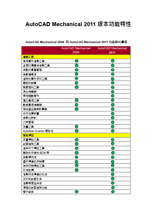
AutoCAD Mechanical 2011版本功能特性AutoCAD Mechanical 2008 和AutoCAD Mechanical 2011功能對比圖表為含有此功能和AutoCAD Mechanical 2008相比,新版本的AutoCAD Mechanical 2011在三年內對軟體功能進行了一系列的改進和革新,無論是在大的功能革新上還是在細節的增強上,都有較大的跨越。
首先將08版本之後幾個版本的比較突出的功能更新列舉如下:AutoCAD Mechanical 2009增加了標準零件我的最愛功能,根據您的工作流程訂制AutoCAD Mechanical。
使用者現在可以儲存自己喜歡的常用零件,以便日後需要再使用時迅速調用。
同時AutoCAD Mechanical 2009在標註尺寸功能、2D隱藏、件號和BOM 表等功能做了增強,能夠幫助設計人員快速更改、編輯或刪除標註,自動產生可隨工程圖修訂自動更新的隱藏線,從而減少繪圖工作量。
同時可以實作使用標準的件號並自動更新BOM表,以無縫跟蹤所有變更,確保團隊如期準確無誤地完成工作。
AutoCAD Mechanical 2010在各功能模組上進行了更具革命性的革新。
首先,AutoCAD Mechanical 2010在可用性、工作效率和品質方面進行了重要改進,在使用者介面方面採用了最新的ribbon介面,使得客戶更加方便地選擇繪圖工具,同時也可以將使用者介面設置為使用者習慣地典型介面,使得使用者依然可以在熟悉的介面下進行設計工作。
同時2010版本對符號庫等方面做了更全面的擴展,更大地方便了客戶進行圖紙繪製和編輯。
其次,AutoCAD Mechanical 2010採用了參數化設計工具,實現了圖面的幾何約束和尺寸約束,使得設計人員能夠利用參數化功能對圖面進行編輯和修改,較大地提高了設計效率。
最後,AutoCAD Mechanical 2010對零件庫的發佈和BOM表移植也做了重要革新,用戶可以訂制自己的企業標準,將企業標準零件放置於標準圖庫中,同時設計人員也可以對圖面進行範本萃取和BOM表移植工作,有效地提高了設計效率。
- 1、下载文档前请自行甄别文档内容的完整性,平台不提供额外的编辑、内容补充、找答案等附加服务。
- 2、"仅部分预览"的文档,不可在线预览部分如存在完整性等问题,可反馈申请退款(可完整预览的文档不适用该条件!)。
- 3、如文档侵犯您的权益,请联系客服反馈,我们会尽快为您处理(人工客服工作时间:9:00-18:30)。
CAD STANDARDS & PROCEDURES CADMANUAL 2011Index 1. General1.0 General2.0 Dimensions3.0 Text4.0 Computer Drawing File numbering5.0 Standard Layers6.0 Titles, North point and scale bars7.0 X-ref (external reference)8.0 Revisions9.0 Drawing set-up10.0 Model space vs Paper space11.0 Plot Information12.0 Layer Manager13.0 Process Symbols1.0 GENERALAll drawings shall use the following :1. Standard symbols from the symbols library ; if no symbol exists contact the DM2. Standard layers as outlined in the layers section ; do not put objects in the wronglayer3. Text as described in the text section ; sizes and fonts to be uniform4. General notes and keyed notes should show on the right corner of title block5. Associative dimensioning ; do not explode dimensions or change figures in thedim text6. Standard title blocks available in the library ,form as A4,A3,A1,A07. Use model space for base xref drawing and use paper space for the title block &plot drawings8. Create viewports as necessary9. Always use OSNAP functions for accuracy pointing and selecting objects10. Insertion point should always be 0,0,011. VISRETAIN should always be set at 1 to enable the xref layers to be retained2.0 DIMENSIONING1. All dimensioning should be in model space2. If more than one scale is required for dimensioning multiple viewports use multiplierof scale for style name3. For architectural drawings use the tick style4. Place dimensions so that they are clearly read and not overlapping importantdrawing information and graphics5. Dimstyle should have text height of 2.5 with colour yellow for text6. Use associative dimensioning only and do not explode the dimensionsAnnotation setting up boxFormat setting up boxPrimary Units setting up boxGeometry setting up box3.0 TEXTText font Romans for all normal text, notes, dimensions, subtitlesText font Romans for presentation drawingsGeneral rule for text heights1. Standard text for notes……2.5mm when plotted2. Dimension text……… 2.5mm when plotted3. Subtitle text ……… 5.0mm when plotted4. Title text…… 7.0mm when plottedLeaders are to be placed in the same layer as the noting layerGeneral notes and keyed notes should be placed on the top right hand corner of the drawing sheetGeneral notes are always to be placed first and then the keyed notes below General notes are to be used to clarify and supplement drawing information4.0 COMPUTER DRAWING FILE NUMBERING∙All the drawing name and file numbering should be named in principle as follows: X – xxx xxxxxxDrawing title descriptionDrawing numbers (as described below)Discipline prefix∙Drawing title description is to describe the character of file that should be unique. ∙Revision code indicates the new update Revision by character A to Z. If revision code over Z then could start from AA to AZ and till to ZZ.∙Drawing numbering should be as follows:Drawing No. A – AD-112 indicates the file is an Architecture drawing for Admin building’s and thedrawing number is 112.∙Discipline Prefix:A ArchitecturalC CivilE ElectricalF Fire Protection ServicesG GeneralI Instrumentation and ControlsM Mechanical (HVAC)P PlumbingPP Process PipingS StructuralT Telecommunications5.0 STANDARD LAYERSTo provide consistency and uniformity between work groups follow a standard layering system as noted belowXX –xxx - xxx xxxHeight and other dimensionsMaterial nameGroup nameDiscipline prefixFor example:Layer A-w-dsf1200 indicate Dado Split face block wall (height is 1200) in walls group which belong to Architecture drawingGENERALDiscipline PrefixLayer name Color Linetype Description-VP 7(white) continuousVport layer for paper space0 7(white) continuous0 layer for inserting drawingsDefpoints 7(white) continuousLayer for supplementary line which willnot show when the drawing plot outARCHITECTURALDiscipline PrefixLayer name Color Linetype Description A AREAA-A-BAO 4(cyan) continuousBuilding area outlineA-A-RAO 4(cyan) continuousRoom area outlinesA-A-SAO 4(cyan) continuousSite area outlineA CEILINGA-C-GC 254(grey) continuousGrid ceilingA-C-SPB 254(grey) continuousSet plasterboard ceilingA-C-SC 254(grey) continuousSuspended ceiling eg. Bulkheads etc.A-C-AT254(grey) continuousAcoustic tileA DETAILSA-DE-P20 7(white) continuousDetail plan 1:20 ( showing relevantscale)A-DE-S20 7(white) continuousDetail section 1:20 ( showing relevantscale)A DOORSA-D-G 3(green) continuousGlazed doorsA-D-GSF 3(green) continuousGlazed shop frontsA-D-T 3(green) continuousTimber doorsA-D-MF 3(green) continuousMetal faced doorsA-D-R 3(green) continuousRoller doorsA ELEVATIONSA-E-E 7(white)continuousExterior elevations A-E-I 7(white)continuousInterior elevations A-E-O 4(cyan)continuousOutlineA-E-GRD 4(cyan)continuousGround lineA EQUIPMENTA-EQ-EF 7(white) continuousElectrical fittings(lights, switches, ACdiffusers)A-EQ-MF 3(green) continuousMechanical fittings(pumps,tanks,compressors)A-EQ-PF 7(white) continuousPlumbing fittings (wc suites, basins,tubsetc.)A FLOORINGA-F-CF 254(grey) continuousComputer floorA-F-CT 254(grey) continuousCeramic tileA-F-CPT 254(grey) continuousCarpetA-F-EP 254(grey) continuousExternal pavingA-F-SCF 254(grey) continuousSpecial coatings finishA-F-SFF 254(grey) continuousSelective tile floor finish (marble,granite)A-F-VT 254(grey) continuousVinyl tilesA FURNITUREA-FU-F 7(white) continuousFixed furniture (overhead cabinets,cupboards)A-FU-L 7(white) continuousLoose furniture (tables, chairs, desksetc.)A-FU-S 7(white) continuousSpecial furniture systemsA GENERALA-G-CSHD 254(grey) continuousColor shade for presentation drawingsA-G-DIM 7(white) continuousDimensions indicating the plotted scaleA-G-DIM2 7(white) continuousDimensions indicating the plotted scaleA-G-DIM5 7(white) continuousDimensions indicating the plotted scaleA-G-DIM10 7(white) continuousDimensions indicating the plotted scaleA-G-DIM20 7(white) continuousDimensions indicating the plotted scaleA-G-DIM50 7(white) continuousDimensions indicating the plotted scaleA-G-DIM100 7(white) continuousDimensions indicating the plotted scaleA-G-DIM200 7(white) continuousDimensions indicating the plotted scaleA-G-DIM500 7(white) continuousDimensions indicating the plotted scaleA-G-GD 254(grey) center Grid line for drawing environmentA-G-HAT 254(grey) continuousCross hatch for different materialsA-G-HAT2 254(grey) continuousCross hatch for different materialsA-G-LEG 7(white) continuousLegends for different samplesA-G-REV 2(yellow) dashed Revision cloud and number triangleA-G-RD 7(white) continuousRoad line of the siteA-G-RL 7(white) center Red line of the siteA-G-SHD 254(grey) continuousFill for shading particular areasA ROOFA-R-C 3(green) continuousConcrete roofA-R-M 7(white) continuousMetal roofing system (including roofwalkways, ladders, penetrations,platforms, handrails etc.)A-R-MR 7(white) continuousMetal gutters and Down pipes (rainwatergoods)A SECTIONSA-SEC-T 2(yellow) continuousTimber/wood elements in sectionA-SEC-GND 2(yellow) continuousGroundA STAIRCASEA-ST-H 3(green) continuousHandrail for staircaseA-ST-ST 7(white) continuousSteps for staircaseA STRUCTUREA-STR-CCL6(magenta)continuousconcrete column A-STR-CB 7(white)continuousConcrete beam A-STR-GT 7(white)continuousgirtA-STR-PL 7(white)continuouspurlinA-STR-SCL 4(cyan)continuousSteel columnA-STR-SB 7(white) continuou Steel beamsA-STR-SW 7(white) continuousGeneral steel workA-STR-CS 4(cyan) continuousConcrete slabA SYMBOLSA-SYM-DE 7(white) continuousDetail bars and associated textA-SYM-NP 4(cyan) continuousNorth point and scale barsA-SYM-SC 2(yellow) continuousScale bars and associated textA-SYM-SB 7(white) continuousSection bars and associated textA-SYM-TB 7(white) continuousTitle block text and symbolsA-SYM-BRK 7(white) continuousBreak lineA TEXTA-TXT-DN3(green) continuousDoor number textA-TXT-FL 7(white) continuousFloor finish textA-TXT-LVL 7(white) continuousLevels textA-TXT-NTS 7(white) continuousNotes textA-TXT-RNA 7(white) continuousRoom name textA-TXT-RNO 3(green) continuousRoom number textA-TXT-WN 3(green) continuousWindow number textA-TXT-W 7(white) continuousWall type textA-TXT-TTL 4(cyan) continuousTitle textA WALLSA-W-BWF 4(cyan) continuousBrick wall full height plaster paintedA-W-BWS 4(cyan) continuousBrick wall sill height plaster paintedA-W-CAP 3(green) continuousComposite aluminum PVF clad wallsA-W-CMU 2(yellow) continuousConcrete masonry unit wallA-W-CW 2(yellow) continuousConcrete wall panelss stated)A-W-DSF600 2(yellow) continuousDado Split face block wall (to mentionedheight)A-W-DSF1000 2(yellow)continuousDado Split face block wall (to mentionedheight)A-W-DSF1200 2(yellow)continuousDado Split face block wall (to mentionedheight)A-W-DSF1600 2(yellow)continuousDado Split face block wall (to mentionedheight)A-W-DSF1800 2(yellow)continuousDado Split face block wall (to mentionedheight)A-W-DSF2000 2(yellow)continuousDado Split face block wall (to mentionedheight)A-W-DSF2200 2(yellow)continuousDado Split face block wall (to mentionedheight)A-W-DSF2400 2(yellow)continuousDado Split face block wall (to mentionedheight)A-W-DSF2800 2(yellow)continuousDado Split face block wall (to mentionedheight)A-W-FBW 2(yellow) continuousFace block wall full height plasterpaintedA-W-FBW600 2(yellow)continuousFace block wall plaster painted (tomentioned height)A-W-FBW1000 2(yellow)continuousFace block wall plaster painted (tomentioned height)A-W-FBW1200 2(yellow)continuousFace block wall plaster painted (tomentioned height)A-W-FBW1600 2(yellow)continuousFace block wall plaster painted (tomentioned height)A-W-FBW1800 2(yellow)continuousFace block wall plaster painted (tomentioned height)A-W-FBW2000 2(yellow)continuousFace block wall plaster painted (tomentioned height)A-W-FBW2200 2(yellow)continuousFace block wall plaster painted (tomentioned height)A-W-FBW2400 2(yellow)continuousFace block wall plaster painted (tomentioned height)A-W-FBW2800 2(yellow)continuousFace block wall plaster painted (tomentioned height)A-W-SFB 2(yellow) continuousSplit face block wall full heightA-W-SFB600 2(yellow) continuousSplit face block wall (to mentionedheight)A-W-SFB1000 2(yellow)continuousSplit face block wall (to mentionedheight)A-W-SFB1200 2(yellow)continuousSplit face block wall (to mentionedheight)A-W-SFB1600 2(yellow)continuousSplit face block wall (to mentionedheight)A-W-SFB1800 2(yellow)continuousSplit face block wall (to mentionedheight)A-W-SFB2000 2(yellow)continuousSplit face block wall (to mentionedheight)SFB2200 s height)A-W-SFB2400 2(yellow)continuousSplit face block wall (to mentionedheight)A-W-SFB2800 2(yellow)continuousSplit face block wall (to mentionedheight)A-W-SSP 7(white) continuousSteel stud plasterboard wall paintedA-W-SSF 7(white) continuousSteel stud fiber cement sheet wallpaintedA-W-SSW 7(white) continuousSteel stud wet wall system ceramic tilefinishA-W-PCW 2(yellow) continuousPrecast concrete walls plaster paintedA-W-MWC 7(white) continuousMetal wall claddingA WINDOWSA-WI-AF 7(white) continuousAluminum farmed window systems,curtain wallsFull height windows, glazing mullionsetcA-WI-PG 7(white) continuousPartition glazed windows, viewingpanels etc.MECHANICAL SERVICESDiscipline PrefixLayer name Color Linetype Description M GENERALM-G-DIM 7(white) continuousDimensions indicating the plotted scaleM-G-DIM2 7(white) continuousDimensions indicating the plotted scaleM-G-DIM5 7(white) continuousDimensions indicating the plotted scaleM-G-DIM10 7(white) continuousDimensions indicating the plotted scaleM-G-DIM20 7(white) continuousDimensions indicating the plotted scaleM-G-DIM50 7(white) continuousDimensions indicating the plotted scaleM-G-DIM100 7(white) continuousDimensions indicating the plotted scaleM-G-DIM200 7(white) continuousDimensions indicating the plotted scaleM-G-DIM500 7(white) continuousDimensions indicating the plotted scaleM-G-GD 254(grey) centre Grid line for centresM-G-HATCH 254(grey) continuousCross hatch for different materialsM-G-REV 254(grey) dashed Revision cloud and number triangleM-G-TXT2.5 7(white) continuousStandard text for notes, text height2.5mmM-G-TXT5 6(magenta)continuousSubtitle text, text height 5mmM EQUIPMENTM-E-COMP 2(yellow) continuousCompressor and associated equipmentM-E-HAVC 2(yellow) continuousHVAC equipmentM PIPINGM-P-CA 6(magenta)continuousCompressed air lineM-P-CW 6(magenta)continuousCold water lineM-P-HW 6(magenta)continuousHot water lineM-P-COOLANT 6(magenta)continuousCooling medium lineM-P-DUCT 6(magenta)continuousDuct lineELECTRICAL SERVICESDiscipline PrefixLayer name Color Linetype Description E GENERALE-G-DIM 7(white) continuousDimensions indicating the plotted scaleE-G-DIM2 7(white) continuousDimensions indicating the plotted scaleE-G-DIM5 7(white) continuousDimensions indicating the plotted scaleE-G-DIM10 7(white) continuousDimensions indicating the plotted scaleE-G-DIM20 7(white) continuousDimensions indicating the plotted scaleE-G-DIM50 7(white) continuousDimensions indicating the plotted scaleE-G-DIM100 7(white) continuousDimensions indicating the plotted scaleE-G-DIM200 7(white) continuousDimensions indicating the plotted scaleE-G-DIM500 7(white) continuousDimensions indicating the plotted scaleE-G-REV 254(grey) dashed Revision cloud and number triangle E-G-GD 254(grey) centre Grid line for centresE-G-TXT2.5 7(white) continuousStandard text for notes, text height2.5mmE-G-TXT5 6(magenta)continuousSubtitle text, text height 5mmE EQUIPMENTE-E-Conduit 2(yellow) continuousConduitE-E-CT 2(yellow) continuousCable and cable traysE DIAGRAMSE-D-P 2(yellow) continuousPower distribution diagramsE-D-L 2(yellow) continuousLighting diagramsE-D-I 2(yellow) continuousInstruments and monitoring diagramsFIRE PROTECTION SERVICESDiscipline PrefixLayer name Color Linetype Description F GENERALF-G-DIM 7(white) continuousDimensions indicating the plotted scaleF-G-DIM2 7(white) continuousDimensions indicating the plotted scaleF-G-DIM5 7(white) continuousDimensions indicating the plotted scaleF-G-DIM10 7(white) continuousDimensions indicating the plotted scaleF-G-DIM20 7(white) continuousDimensions indicating the plotted scaleF-G-DIM50 7(white) continuousDimensions indicating the plotted scaleF-G-DIM100 7(white) continuousDimensions indicating the plotted scaleF-G-DIM200 7(white) continuousDimensions indicating the plotted scaleF-G-DIM500 7(white) continuousDimensions indicating the plotted scaleF-G-GD 254(grey) centre Grid line for centresF-G-REV 254(grey) dashed Revision cloud and number triangleF-G-TXT2.5 7(white) continuousStandard text for notes, text height2.5mmF-G-TXT5 6(magenta)continuousSubtitle text, text height 5mmF EQUIPMENTF-E-PEX2(yellow) continuousFire protection pumps for fireextinguisherF-E-PSP 2(yellow) continuousFire protection pumps for sprinklerF-E-FM200 2(yellow) ContinuousCylinders for FM200 systemF-E-CO2 2(yellow) ContinuousCylinders for CO2 systemF PIPINGF-P-EX 6(magenta)ContinuousFire extinguisher lineF-P-SP 6(magenta)ContinuousFire sprinkler lineF-P-FM200 6(magenta)ContinuousFM-200 fire protection systemF-P-CO2 6(magenta)ContinuousCO2 fire protection systemPLUMBING SERVICESDiscipline PrefixLayer name Color Linetype Description P GENERALP-G-DIM 7(white) ContinuousDimensions indicating the plotted scaleP-G-DIM2 7(white) ContinuousDimensions indicating the plotted scaleP-G-DIM5 7(white) ContinuousDimensions indicating the plotted scaleP-G-DIM10 7(white) ContinuousDimensions indicating the plotted scaleP-G-DIM20 7(white) ContinuousDimensions indicating the plotted scaleP-G-DIM50 7(white) ContinuousDimensions indicating the plotted scaleP-G-DIM100 7(white) ContinuousDimensions indicating the plotted scaleP-G-DIM200 7(white) ContinuousDimensions indicating the plotted scaleP-G-DIM500 7(white) ContinuousDimensions indicating the plotted scaleP-G-REV 254(grey) Dashed Revision cloud and number triangle P-G-GD 254(grey) Centre Grid line for centresP-G-TXT2.5 7(white) ContinuousStandard text for notes,text height2.5mmP-G-TXT5 6(magenta)ContinuousSubtitle text, text height 5mmP EQUIPMENTP-E-PUMP3(green) ContinuousPumpsP-E-F 3(green) ContinuousPlumbing fittings (wc suites, basins,tubsetc.)P PIPINGP-P-WS 2(yellow) ContinuousWater supplyP-P-HWS 2(yellow) ContinuousHot water supplyP-P-DRA 2(yellow) ContinuousdrainagePROCESS PIPINGDiscipline PrefixLayer name Color Linetype Description PP GENERALPP-G-DIM 7(white) ContinuousDimensions indicating the plotted scalePP-G-DIM2 7(white) ContinuousDimensions indicating the plotted scalePP-G-DIM5 7(white) ContinuousDimensions indicating the plotted scalePP-G-DIM10 7(white) ContinuousDimensions indicating the plotted scalePP-G-DIM20 7(white) ContinuousDimensions indicating the plotted scalePP-G-DIM50 7(white) ContinuousDimensions indicating the plotted scalePP-G-DIM100 7(white)ContinuousDimensions indicating the plotted scalePP-G-DIM200 7(white)ContinuousDimensions indicating the plotted scalePP-G-DIM500 7(white)ContinuousDimensions indicating the plotted scalePP-G-REV 254(grey) Dashed Revision cloud and number triangle PP-G-GD 254(grey) Centre Grid line for centresPP-G-TXT2.5 7(white)ContinuousStandard text for notes, text height2.5mmPP-G-TXT5 6(magenta)ContinuousSubtitle text, text height 5mmPP EQUIPMENTPP-E-M 2(yellow) ContinuousMachines for processPP-E-T 2(yellow) ContinuousProcess tanksPP-E-EX 2(yellow) ContinuousProcess heat exchangersPP-E-P 2(yellow) ContinuousProcess pumpsPP-E-C 2(yellow) ContinuousProcess conveyorsPP PIPINGPP-P-S 3(green) ContinuousProcess service linePP-P-P 6(magenta)ContinuousProduct linePP-P-SV 7(white) ContinuousValves for process servicePP-P-PV 7(white) ContinuousValves for productPP-P-PC 7(white) ContinuousOther components for productsPP-P-SC 7(white) ContinuousOther components for process service6.0 Titles, North points and Scale barsTitlesUse the following 6 different titles typically1. General notes title (top right hand corner of title sheet)2. Keyed notes title (below general notes)3. Subtitle (describing PLAN or ELEVATION etc)4. Title with north point (describing PLAN )5. Title with detail symbol (describing DETAIL and cross referencing it)6. Main title (main drawing information PROJECT No. etc)Do not draw lines or underline titlesNorth pointsUse north points available in the libraryLocate north point in the top right hand vacant block of the title page above the general notesScale barsUse scale bars on drawings that are to be plotted to fit and not to a relevant scaleFull size working drawings need not have the scale bars7.0 Xref (EXTERNAL REFERENCE)When an external reference (xref) is attached or overlayed in a drawing it is for reference onlyIt is an external file and any changes made to it will change the files referencing itThe xref should be reloaded so the changes can be updatedBinding this xref will make it a permanent part of the drawing file and any future revisions to the xref will not occur in the bound xref.An xref maybe inserted into a drawing as a block but should not be explodedAll the xref drawings should be xrefed in at the 0,0,0 point only8.0 REVISIONSThe revision column should be used to show the changes to the drawing the date the changes were made and the revision numberKeep the description of the changes brief but identify all changesCloud all revision areas and mark up the cloud with a triangle and numberDelete previous clouds and numbers as new clouds are addedISSUE Notes will be indicated with alphabetical letters and used only to issue drawings REVISION Notes. will be indicated with numericals and used to identify progressive revisions9.0 DRAWING SET-UPAll drawing files are to be drawn 1:1Orientation of the plan view files are always at the 0,0 insertion point10.0 MODEL SPACE vs PAPER SPACEDrawing file information is in model space of the plan viewPaper space contains the title block with revision controls, clouds and revision triangles11.0 PLOT INFORMATIONa) Rotation and OriginPlot Rotation 00 (generally)Plot Origin x origin 10.00y origin 5.00b) Device and Continuous SelectionHP Design Jet 700, HP Design Jet 650C Pen Assignments:(BI & A0 Sheets)Color Pen No. Linetype Pen Width Colour Shaded Line1 1 0 0.18 Red2 2 0 0.35 Yellow3 3 0 0.25 Green4 4 0 0.70 Cyan5 5 0 0.35 Blue6 6 0 0.50 Magenta7 7 0 0.25 White8 8 0 0.10 8 (dark grey)9 9 0 0.13 9 (light grey)20 20 0 - 20 5%21 21 0 - 21 10%22 22 0 - 22 20%23 23 0 - 23 30%24 24 0 - 24 40%25 25 0 - 25 50%250 250 0 - 250 50%251 251 0 - 251 40%252 252 0 - 252 30%253 253 0 - 253 20%254 254 0 - 254 10%255 255 0 - 255 5%(A1 Sheets)Color Pen No. Linetype Pen Width Colour Shaded Line1 1 0 0.13 Red2 2 0 0.25 Yellow3 3 0 0.18 Green4 4 0 0.58 Cyan5 5 0 0.28 Blue6 6 0 0.35 Magenta7 7 0 0.18 White8 8 0 0.07 8 (dark grey)9 9 0 0.09 9 (light grey)20 20 0 0.14 20 5%21 21 0 0.14 21 10%22 22 0 0.14 22 20%23 23 0 0.14 23 30%24 24 0 0.14 24 40%25 25 0 0.14 25 50%250 250 0 0.14 250 50%251 251 0 0.14 251 40%252 252 0 0.14 252 30%253 253 0 0.14 253 20%254 254 0 0.14 254 10%255 255 0 0.14 255 5%(B2 & A2Sheets)Color Pen No. Linetype Pen Width Colour Shaded Line1 1 0 0.13 Red2 2 0 0.25 Yellow3 3 0 0.18 Green4 4 0 0.58 Cyan5 5 0 0.28 Blue6 6 0 0.35 Magenta7 7 0 0.18 White8 8 0 0.07 8 (dark grey)9 9 0 0.09 9 (light grey)20 20 0 0.14 20 5%21 21 0 0.14 21 10%22 22 0 0.14 22 20%23 23 0 0.14 23 30%24 24 0 0.14 24 40%25 25 0 0.14 25 50%250 250 0 0.14 250 50%251 251 0 0.14 251 40%252 252 0 0.14 252 30%253 253 0 0.14 253 20%254 254 0 0.14 254 10%255 255 0 0.14 255 5%HP LASER JET 4V, HP LASER JET 5000 Pen Assignments:(A3Sheets)Color Pen No. Linetype Pen Width Colour Shaded Line1 7 0 0.08 Red2 7 0 0.25 Yellow3 7 0 0.12 Green4 7 0 0.60 Cyan5 7 0 0.35 Blue6 7 0 0.30 Magenta7 7 0 0.12 White8 7 0 0.08 8 (dark grey)9 7 0 0.05 9 (light grey)250 250 0 0.10 250 50%251 251 0 0.10 251 40%252 252 0 0.10 252 30%253 253 0 0.10 253 20%254 254 0 0.10 254 10%255 255 0 0.10 255 5% EPSON STYLUS PHOTO EX2 Pen Assignments:(Color A3)Color Pen No. Linetype Pen Width Colour Shaded Line1 1 0 0.12 Red2 2 0 0.20 Yellow3 3 0 0.15 Green4 4 0 0.30 Cyan5 5 0 0.35 Blue6 6 0 0.30 Magenta7 7 0 0.12 White8 8 0 0.08 8 (dark grey)9 9 0 0.08 9 (light grey)250 250 0 0.10 250 50%251 251 0 0.10 251 40%252 252 0 0.10 252 30%253 253 0 0.10 253 20%254 254 0 0.10 254 10%255 255 0 0.10 255 5%(Black & White A3)Color Pen No. Linetype Pen Width Colour Shaded Line1 7 0 0.12 Red2 7 0 0.20 Yellow3 7 0 0.18 Green4 7 0 0.25 Cyan5 7 0 0.35 Blue6 7 0 0.30 Magenta7 7 0 0.15 White8 7 0 0.08 8 (dark grey)9 7 0 0.08 9 (light grey)250 250 0 0.10 250 50%251 251 0 0.10 251 40%252 252 0 0.10 252 30%253 253 0 0.10 253 20%254 254 0 0.10 254 10%255 255 0 0.10 255 5%c) Paper Size and OrientationAlways in Millimeters mmSize B1 1000 ⨯ 707A0 840 ⨯ 1188A1 840 ⨯ 594A2 420 ⨯ 594A3 420 ⨯ 297A4 210 ⨯ 29714.0 Layer managerLayer manager should be used in xref drawings that will help the layers arrange clearer and easier.Layer manager should make different layer group separately like ceiling group, floor finish group, doors and windows layer group, process group, etc.In one layer system, we should have a standard *.lay file saved in same folder, so in same system we can share the file with other drawings.15.0 Process Symbol。
