burkert-1067-定位器
宝德8692型定位器-快速入门中文说明书

正确使用
警告!
如不正确使用 8692 / 8693 型定位器,则可能对人体、附 近的设备以及环境造成危害。
• 该设备不可用于室外。 • 该设备不可暴露在直射阳光下。 • 该设备只能与经 Bürkert 认可和推荐的第三方设备及
组件配套使用。 • 由于其可能的应用范围较广,请确认该定位器是否适
空! 触电危险! 伸手到设备内部具有触电危险。 • 伸手到设备内部之前,请先切断电源并确认,以防止
重新启动! • 遵守电气设备适用的事故预防和安全规则!
警告! 由于意外启动而导致的受伤危险。 • 采取适当措施防止该设备意外启动!
6
5
警告! 安装和维护过程中可能导致危险。
• 只能由获得授权的技术人员采用合适的工具进行安装 与维护!
或站在其上。)
• 不要对该设备的外壳作任何外部修改。不要将其外壳或 螺钉等进行喷涂。
根据 8692 型和 8693 型定位器的使用说明、使用条件、 允许的参数(参见本快速入门中和相关气动阀资料中的 技术参数一章),确保该设备无故障运行并具有较长的 使用寿命。
4
基本安全说明
危险! 高压危险! • 拆卸阀门与管道之前,请先关闭压力入口并将管道排
过程设定值
POS %
XXX
MENU INPUT CMD MANU
CMD %
XXX
MENU POS TEMP MANU
TEMP *C
XX.X
MENU CMD INPUT
显示阀门执行机构的 实际位置 (0 – 100%)
显示阀门执行机构的 设定位置 (0 – 100%)
定位器内部的温度 (°C)
XXX SP
功能
Amprobe UAT-600地下设施定位器系列用户说明书

Accidentally hitting a utility line during a project can lead to costly repairs and create hazardous public safety situations. Digging in the wrong place can also lead to unnecessary delays and costs for your project, and ultimately, your company. Avoid this disruption with the rugged and durable Amprobe UAT-600 Series, designed to accurately pinpoint underground utilities and buried services up to 20 feet deep.Designed for electricians with a CAT IV 600 V rating, the locating kits come complete and ready for use with a Transmitter, Receiver, test lead kit, batteries and additional fuses, all in a mobile, protective duffle bag.The UAT-620 kit also includes a Signal Clamp for transmitting a signal when it is not possible to make electrical contact with the cable to be traced. For applications where ground fault locating is required, use the UAT-600 Transmitter in combination with the optional A-Frame accessory.Intuitive Transmitter automatically chooses the correct locatingfunctionSC-600 Signal Clamp included in the UAT -620 KitLarge LCD Display with auto backlight for clear viewing in full sunlightLocateunderground utilities up to 20 ft.UAT -600 SeriesUnderground Utilities LocatorAccurately and safely pinpoint underground utilities before you digUAT -620Underground Utilities Locator KitAF-600 A-Frame Accessory*Ground Fault FinderSee page 2 for specifications* (Not included in the UAT-610 and UAT-620 Kits)Safety CertificationAll Amprobe tools, including the Amprobe UAT-600 Series, are rigorously tested for safety, accuracy, reliability, and ruggedness in our state-of-the-art test lab. In addition, Amprobe products that measure electricity are listed by a 3rd party safety lab, either UL or CSA. This system assures that Amprobe products meet or exceed safety regulations and will perform in a tough, professional environment formany years to come.Features and Highlights• Multiple tracing modes allow you to locate and trace energized and de-energized utilities in a variety of applications• The intuitive Transmitterautomatically chooses the correctlocating function based on the connectedaccessory and includes selectable 8/33kHz frequencies• The Receiver’s high-contrast display allows for clear viewing in full sunlight and features an automatic backlight for shaded and dark areas• Rated CAT IV 600 V , ensuring safety when working with energized cables • Semi-automatic gain control quickly detects tracing signal and allows precise adjustment of the receiver sensitivity• Accurate depth measurement to 20 ft• Rugged, durable construction: water and dust resistant to IP54 and drop proof to 3.28 ft (1 m)• Use the Signal Clamp to induce asignal without making electrical contact (UAT -620)• Ground fault locating with the optional A-Frame accessory • Comes as a complete kit, ready for useLCD Display with autobacklightDetect ground faults on cables and pipesAF-600-A-FrameGround Fault FinderAF-600 A-FrameGround Fault FinderSave time and money by pinpointing leakage pointsGround faults are a common problem with electrical cables. Find any fault with the AF-600 A-Frame cable ground fault finder, specifically designed for use with the Amprobe UAT -600 Series.Set up the UAT -600-T Transmitter to apply a fault find signal to the utility under test, the AF-600 A-Frame receives the signal and locates the place of the fault. The AF-600 will pinpoint where a cable metal conductor (either a sheath or a metallic conductor of the wire) touches the ground and can also detect other conductors to ground faults such as pipeline coating defects.Carrying Case, User ManualThe AF-600 comes complete with batteries and a carrying caseFeatures and Highlights • Identify any point of leakage around a cable • Locate cable and wire ground faults, sheath faults or pipeline coating defects, where the utility is in direct contact with the ground • Find the exact point where metal is touching the ground and power is leaking, ie, a shield is rusted or a rubber buffer is broken, creating noise on a cable • Advanced technology and digital signal processing makes pinpointing process fast, accurate and clear:-Compass guidance with numeric fault field strength indicates the direction of the fault -Distance sensitive left and right arrows guides the user to precisely follow the path of the buried utility-Automatic gain control quickly detects tracing signal and precisely adjusts the A-Frame sensitivity-Adjustable volume controlsClearly view the LCD display in bright sunlightPinpoint fault location by using the AF-600 with the UAT-600 TransmitterSC-600Signal ClampTL-UAT -600Test Leads KitSC-600 Signal Clamp(included in the UAT -620 Kit only)The Signal Clamp accessory provides an efficient and safe method of applying a locate signal to a cable, enabling the Transmitter to induce a signal through the insulation into the wires or pipes. The clamp works on low impedance closed circuits only.Test Leads Kit(included in the UAT -610 and UAT -620 Kits)TL-UAT -600 Test Leads Kit includes: Black test lead with detachable black alligator clip, Red test lead with permanently attached red alligator clip, Ground stakeTrace an individual utility by connecting the The Transmitter will automatically change modes The Receiver’s high contrast LED screen is easy toUAT-620 Underground Utilities Locator Kit。
burkert调节阀设置方法

burkert调节阀设置方法Burkert调节阀是一种常见的流体控制设备,用于调节液体或气体的流量和压力。
正确的设置和配置是确保该设备正常运行的关键。
以下是Burkert调节阀设置的详细介绍:1. 压力范围:首先,您需要确定调节阀的工作压力范围。
这可以在阀门上找到或咨询制造商。
选择正确的压力范围有助于确保设备可以按照预期的方式工作。
2. 连通示意图:在使用Burkert调节阀之前,请确保理解全套传感器的连通示意图。
这有助于您更好地理解流量和压力的传感器工作原理。
如果您不确定,可以在官方网站或制造商的用户手册中找到更多信息。
3. 标定传感器:标定传感器可以确保精确的读数和调节,尤其是在测量低流量和压力时。
这可以通过一个专门的传感器进行操作。
在进行校准之前,请确保将传感器连接到一个已知值的压力和温度源。
4. 不同的控制器:Burkert调节阀配备了各种不同的控制器,包括电子、气动和液压控制器。
选择适合您的应用的控制器非常重要。
通常,电子控制器用于高精度应用,而气动和液压控制器用于需要快速响应和较高流量的应用。
5. 初次运行:在使用Burkert调节阀之前,需要进行初次运行,以确保设备正常工作并按照预期工作。
此时应该检查阀门的密封性能和压力范围。
此时应该注意防止阀门堵塞、泄漏和操作不当。
6. 对于自动控制的调节阀,我们需要先了解控制系统的架构、信息的传递规律和作用参数,再进行控制器的选择、设定参数的设置。
比如在使用PID控制时,需要先调节好比例系数、积分时间和微分时间等。
总结:在使用Burkert调节阀之前,您需要了解的不仅仅是设备的工作原理,还需要了解阀门的设置和配置方法。
您可以根据上述指南来正确地设置和配置调节阀,以确保设备的正常工作。
在应用过程中,您还应该关注设备的维护和保养,以确保设备的长期稳定性和有效性。
汽车连接器标准QCT1067解析
汽车连接器标准QC/T-1067解析随着中国汽车工业的飞速发展,汽车从满足最初的运输功能,扩展到现在具有非常多的安全性、舒适性功能。
随着功能的增加,作为汽车关键部件的汽车连接器从以前一辆车使用几十个发展到如今一辆车用几百个连接器,一百多个品种;从以前的6.3规格发展到现在的0.64规格。
而这一百多种连接器分布在驾驶室、车身、车门、发动机舱、变速器等地方,因为不同地方连接器的使用温度、振动等级的不同,对连接器的防护等级的要求不同,所以不同的使用环境对连接器的性能要求也不相同。
当前连接器标准非常多,从较早的国际标准ISO 8092、SAE标准USCAR-2,到目前中国最新修订的行业标准QC/T-1067-2017 (替代QC/T-417)。
同时很多的汽车企业也定义了属于自己企业的连接器标准,如大众公司的VW 75174、通用的GMW-3191、上汽集团的SMTC 3 862 001、吉利汽车的Q/JLYJ7110195C等。
连接器标准QC/T-1067对连接器使用环境的定义对于一款连接器,在研发之初都会在其规格书中定义出该连接器的使用环境温度、载流能力、防护等级、抗振等级等规格参数,连接器选型工程师需要了解到不同的使用环境对连接器的不同要求,这一点在目前的使用标准中也有很详细的定义。
QC/T-1067的标准定义见表1~表3:表1 QC/T-1067温度等级表2 QC/T-1067振动等级表3 QC/T-1067密封等级表4 QC/T-1067振动等级关于振动实验,我们主要验证的是连接器系统在模拟实际车载振动条件下的性能是否满足要求,因为在振动或者振动冲击情况下,会引起端子接触面的镀层磨损、正压力衰减、支撑塑料材料的机械性能失效等,所以需要在振动实验中连续监控接触电阻并保证线路中接触电阻超过7Ω(或者1Ω)的时间不能超过1微秒。
对连接器使用环境的定义与分析,我们了解到在对某个功能进行连接器选型时,首先要了解到该功能的使用位置,根据使用位置判断出需要适配的连接器耐受的温度等级、振动等级、防护等级,并进行最佳选型。
多效蒸馏水机说明书

内螺旋列管式多效蒸馏水机使用说明书NLD(300~5000-4~6)(Ⅰ,Ⅱ,Ⅲ,Ⅳ)蒸馏水产量:300、500、1000、1500、2000、3000、4000、5000 (kg/h)中国·山东淄博华周制药设备有限公司一、简介┅┅┅┅┅┅┅┅┅┅┅┅┅┅┅┅┅┅┅┅┅┅┅1二、用途┅┅┅┅┅┅┅┅┅┅┅┅┅┅┅┅┅┅┅┅┅┅┅1三、型号说明┅┅┅┅┅┅┅┅┅┅┅┅┅┅┅┅┅┅┅┅┅1四、型号表┅┅┅┅┅┅┅┅┅┅┅┅┅┅┅┅┅┅┅┅┅┅1五、技术参数表┅┅┅┅┅┅┅┅┅┅┅┅┅┅┅┅┅┅┅┅2六、尺寸表┅┅┅┅┅┅┅┅┅┅┅┅┅┅┅┅┅┅┅┅┅┅3七、结构简图┅┅┅┅┅┅┅┅┅┅┅┅┅┅┅┅┅┅┅┅┅4八、工艺流程图┅┅┅┅┅┅┅┅┅┅┅┅┅┅┅┅┅┅┅┅5九、自动控制概述┅┅┅┅┅┅┅┅┅┅┅┅┅┅┅┅┅┅┅6十、设备安装┅┅┅┅┅┅┅┅┅┅┅┅┅┅┅┅┅┅┅┅┅8 十一、调试准备┅┅┅┅┅┅┅┅┅┅┅┅┅┅┅┅┅┅┅┅9 十二、操作指南┅┅┅┅┅┅┅┅┅┅┅┅┅┅┅┅┅┅┅┅10 十三、设备维护┅┅┅┅┅┅┅┅┅┅┅┅┅┅┅┅┅┅┅┅17 十四、设备除垢┅┅┅┅┅┅┅┅┅┅┅┅┅┅┅┅┅┅┅┅18 十五、注意事项┅┅┅┅┅┅┅┅┅┅┅┅┅┅┅┅┅┅┅┅19一、简介NLD系列内螺旋多效蒸馏水机,经本公司历经多年的开发研制而成,其结构为内螺旋三级分离技术,是国内最先进的机型。
其各项指标均符合《YY0229—1995》标准规定,蒸馏水内毒素<0.125Eμ/ml,产水质量完全符合2005年版药典“注射用水”规定。
本设备由蒸发器、预热器、冷凝器、机架、水泵及自动控制系统等部件组成,整机结构匀称、美观,设备运行稳定、可靠。
过流零部件均采用进口316L材质,确保水质更加纯净;自动控制零部件均采用原装进口件,确保故障率更低;设备阀门及控制按钮均设有手动操作开关,能手动运行并确保连续正常生产;换热器采用密集形列管结构;蒸发器采用降膜蒸发原理多效蒸发;汽水分离装置采用独特的内螺旋三级分离技术(即双层螺旋和除沫器),本结构为国内首创,确保纯蒸汽与其中夹带的微小水滴彻底分离。
调节阀整定及应用缺陷分析
调节阀的整定及应用缺陷分析摘要:调节阀在工业应用过程中,调节阀的整定是对其线性度、零点、量程的校验设定,是确保实现工艺控制性能的有效方法。
在不同的安装应用环境中,为满足生产安全运行的需要,针对不同的介质、压力、温度、流量、压差,调节阀要解决本身固有的缺陷。
本文就调节阀的整定,和对其常见的缺陷分析及解决方案进行总结论述。
关键词:调节阀;整定;应用缺陷分析一、调节阀的整定:1、山武avp-100调节阀定位器山武avp-100调节阀定位器是一款能自动调校的定位器,是本人认为调试最为方便的,通上气源调好空气减压器压力表,打开定位器前盖,给定18ma电流信号,按下”up”键3秒钟,就开始自整定,观察阀杆与标尺,阀杆走完上下两个行程,会在中间位置(50%)微调,选择中间位置,最后停留在标尺的87.5%位置(充气伸出型膜头),或25%位置(充气缩回型膜头)。
看膜头进气管在上部(伸出)或是在下部(缩回)便知。
一定要注意最后停留位置,否则自整定无效。
因为不同的调节阀自整定的时间不同,一般2min左右。
2、萨姆森4763定位器萨姆森4763定位器,首先,接通气源和信号源,打开定位器前盖,可以发现三个调整旋钮,”z”零点,”xp”增益(比例度),”q”输出气量。
增大或减小”q”输出气量调整,直到得到满意的定位速度,可通过按动范围弹簧观察效果。
给定50%的控制信号输入给定位器,转动”z”整螺丝,控制阀位是行程中间值。
调整”xp”增益(比例度),因”xp”是在气路放大器之前,并且与喷嘴背压相同,其微小动作可使输出发生很大的变化,所以设置在尽可能小的位置,但过小会造成阀的震荡(气喘)。
如图所示,气源压力在3bar(公斤)时,“xp”预设值在180?皛270?爸p”出厂设置为3%),在调整起点之前,要先调”xp”,然后调零点。
这样下来,行程的线性度基本完成。
下一步调零点,执行器杆伸出型,调整”z”零点,使阀杆刚好从初始位置离开,给定增加至4.5ma信号,使阀杆刚好从初始位置离开,给定20ma信号,阀位应该稳定在100%. 否则移动反馈臂上销钉,改变行程。
宝德8692型定位器-快速入门中文说明书
3 ... 7 bar
7 l N / min (进气和排气) (QNn 值依据压力从 7 bar绝压 下降到 6 bar绝压的定义) 可选:130 lN / min (进气和排气) (仅限单作用阀)
插管接头 Ø6 mm / 1/4" 可按需提供: G1/8
14
工作条件
警告!
180 Ω at 0/4 - 20 mA / 分辨率 12 bit 19 kΩ at 0 - 5/10 V / 分辨率 12 bit 3 ,符合 VDE 0580
10 mA
输出电流0/4 ... 20 mA
时的最大负载
560 Ω
感应接近开关的 电流限值
100 mA
二进制输出 电流限值 二进制输入
电气隔离
l/s
MENU PV POS INPUT*
POS %
XXX
MENU SP CMD MANU
CMD %
XXX
MENU POS TEMP MANU
XXX TEMP
*C
MENU CMD PV
XXX INPUT
mA
MENU TEMP POS
设定位置的输入信号 (0 – 5/10 V / 0/4 – 20 mA)
该定位器有两种电气连接选项: • 多针连接 • 电缆接头
信号参数 电源电压 设定值 (过程设定值 / 位置设定值)
实际过程值 (仅限过程控制器)
24 V DC
0 ... 20 mA; 4 ... 20 mA 0 ... 5 V; 0 ... 10 V
2
所用符号
本手册中使用的符号有: 危险!
警告即时危险! • 如不遵守该警告可能会导致致命的或严重的伤害。
burkert宝德隔膜阀+1067比例调节器带流量计说明书
burkert宝德隔膜阀+1067比例调节器带流量计说明书宝德BURKERT流量计对污水治理流入和排放渠、工矿企业废水排放以及水利工程和农业灌溉用渠道的污水废水的计量需要根据实际不同的流量(比如满管流量和半管流量),管道内的压力不同,选择合适的流量计来测量这些污水。
自然流动或者管道压力比较小不满管流动的时候,推荐使用污水流量计。
宝德BURKERT流量计产品特点:1、宝德BURKERT流量计和断流设备组成,结构简单,成本低。
2、控制箱内的控制线路及组件是根据客户所需要的流量计和设备量身定制的,信号线连接简单,到现场后般无需调整。
3、控制箱面板设有“启动”、“停止”和“清零”按纽,并有“状态指示灯”显示,因此显示直观,操作简单、方便、易学。
4、定量控制仪为全中文液晶显示,每次定量控制值可以根据需要任意更改,只需在定量控制仪内操作完成。
宝德BURKERT流量计积式流量计工作原理:流体通过流量计,就会在流量计进出口之间产生一定的压力差.流量计的转动部件(简称转子)在这个压力差作用下产生旋转,并将流体由入口排向出口.在这个过程中,流体一次次地充满流量计的“计量空间”,然后又不断地被送往出口。
在给定流量计条件下,该计量空间的体积是确定的,只要测得转子的转动次数.就可以得到通过流量计的流体体积的累积值。
工作特点:①计量精度高;②安装管道条件对计量精度没有影响;③可用于高粘度液体的测量;④范围度宽;⑤直读式仪表无需外部能源可直接获得累计,总量,清晰明了,操作简便;⑥结构复杂,体积庞大⑦不适用于高、低温场合;⑧大部分仪表只适用于洁净单相流体;⑨噪声和振动较大。
宝德BURKERT流量计针对该问题,建议通过及时对孔板进行更换或者是检定的方式达到消除误差的目的;再次,是天然气流量计计量管内部大量结构并导致粗糙度有所提供的问题。
宝德BURKERT流量计针对该问题,建议在粗糙度修正无效的条件下,对孔板进行更换,同时将直径比控制在0.3~0.5区域内,或直接对管道进行更新;后,是孔板内部大量堆积污物的问题。
Burkert产品型号2301、2300、2103和2702的数字电动定位器说明书
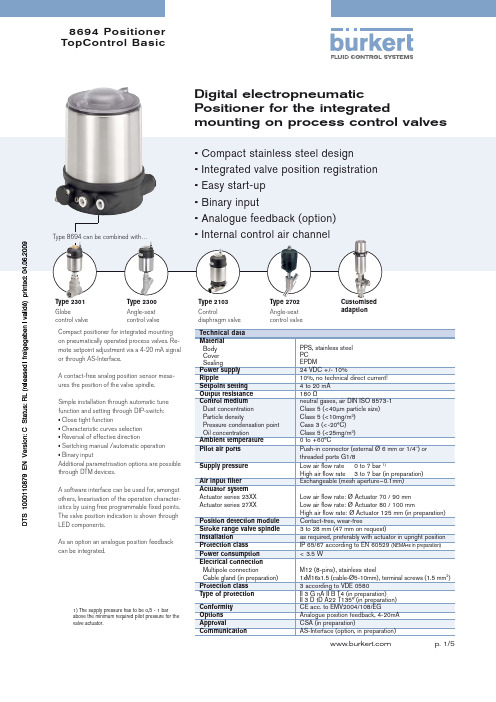
8694 Positioner TopControl BasicType 2301Globecontrol valveType 2300Angle-seat control valveType 2103Controldiaphragm valveType 2702Angle-seatcontrol valveCustomisedadaptionDigital electropneumaticPositioner for the integratedmounting on process control valvesCompact positioner for integrated mounting on pneumatically operated process valves. Re-mote setpoint adjustment via a 4-20 mA signal or through AS-Interface.A contact-free analog position sensor meas-ures the position of the valve spindle.Simple installation through automatic tune function and setting through DIP-switch:• Close tight function• Characteristic curves selection • Reversal of effective direction• Switching manual /automatic operation • Binary inputAdditional parametrisation options are possible through DTM devices.A software interface can be used for, amongst others, linearisation of the operation character-istics by using free programmable fi xed points. The valve position indication is shown through LED components.As an option an analogue position feedback can be integrated.Type 8694 can be combined with…• Compact stainless steel design• Integrated valve position registration • E asy start-up• Binary input• Analogue feedback (option) • Internal control air channelTechnical data Material Body Cover SealingPPS, stainless steel PC EPDMPower supply 24 VDC +/- 10%Ripple10%, no technical direct current!Setpoint setting 4 to 20 mA Output resistance 180 ΩControl medium Dust concentration Particle densityPressure condensation point Oil concentrationneutral gases, air DIN ISO 8573-1Class 5 (<40μm particle size)Class 5 (<10mg/m 3)Cass 3 (<-20°C)Class 5 (<25mg/m 3)Ambient temperature 0 to +60°CPilot air ports Push-in connector (external Ø 6 mm or 1/4") or threaded ports G1/8Supply pressure Low air fl ow rate 0 to 7 bar 1)High air fl ow rate 3 to 7 bar (in preparation)Air input fi lter Exchangeable (mesh aperture~0.1mm)Actuator system Actuator series 23XX Actuator series 27XX Low air fl ow rate: Ø Actuator 70 / 90 mm Low air fl ow rate: Ø Actuator 80 / 100 mm High air fl ow rate: Ø Actuator 125 mm (in preparation)Position detection module Contact-free, wear-freeStroke range valve spindle 3 to 28 mm (47 mm on request)Installationas required, preferably with actuator in upright position Protection class IP 65/67 according to EN 60529 (NEMA4x in preparation)Power consumption < 3.5 WElectrical connection Multipole connectionCable gland (in preparation)M12 (8-pins), stainless steel1xM16x1.5 (cable-Ø5-10mm), terminal screws (1.5 mm 2) Protection class 3 according to VDE 0580Type of protection II 3 G nA II B T4 (in preparation)II 3 D tD A22 T135° (in preparation)Conformity CE acc. to EMV2004/108/EGOptions Analogue position feedback, 4-20mA ApprovalCSA (in preparation)CommunicationAS-Interface (option, in preparation)1) The supply pressure has to be 0,5 - 1 barabove the minimum required pilot pressure for the valve actuator.Ordering information for TopControl-Control valve systemsA complete TopControl-Control valve system consists of a TopControl Basic Type 8694 and a process valve Type 23XX or 27XX . The following information is necessary for the selection of a complete control valve:•Item no. of the Positioner TopControl Basic Type 8694 without process valve, see ordering chart on p. 3•Item no. of the desired process valve Type 23XX or 27XX (see separate datasheets, e.g. 2300, 2301 or 2702, 2712, 2730)•Note: TopControl-Control valve systemWhen you click on the orange box "More info." below, you will come to our website for the resp. product where you can download the datasheet.Valve systemContinuous Classic Type 8802-YC-L 2702 + 86942301 2300 2702 Globe control Angle-seat Angle-seat valve control valve control valve-I -I Valve systemContinuous ELEMENT Type 8802-YG-L 2300 + 8694Ordering chart Type 8694(other versions on request)Ordering chart accessoriesApprovals CSA&URTHERôVERSIONSôONôREQUESTOrdering chart adapter kit(has to be ordered separately)in preparationin preparationDimensions [mm]Mounting on process valve Type 27xxMaterials1Cover PC2Body casing Stainless steel 3Basic body PPS4Plug M12 Stainless steel 5ScrewsStainless steel 6Push-in connector Threaded ports G1/8POM/stainless steel Stainless steel 7SealingEPDMSignal flow diagram Position control loopTopControl Basic functions• Automatic start of the control system• Linear or progressive characteristic curvesselection (DIP-switch); free programmableover Software interface• Close tight function• Reversal of effective direction of the setpointsignal• Switching manual / automatic operation• Binary input (controller enable)• Parametrisation of the device through DTM Schematic diagram of the TopControl Basic1) The operating voltage is supplied with a 3-wire unit independent from the setpoint signal.Connection optionsConnection MultipoleTo fi nd your nearest Bürkert facility, click on the orange box In case of special application conditions,please consult for advice.Subject to alteration.© Christian Bürkert GmbH & Co. KG0906/3_EU-en_00895044。
1062QT 电气反馈和位置监控器 德国伯克特气动执行器 阀门配件说明书
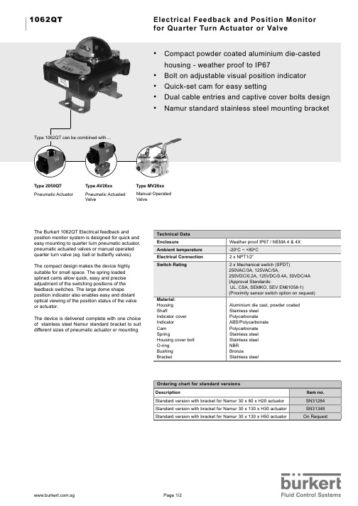
Electrical Feedback and Position Monitor for Quarter Turn Actuator or Valve
• Compact powder coated aluminium die-casted
Ordering chart for standard versions Description Standard version with bracket for Namur 30 x 80 x H20 actuator Standard version with bracket for Namur 30 x 130 x H30 actuator Standard version with bracket for Namur 30 x 130 x H50 actuator
The compact design makes the device highly suitable for small space. The spring loaded splined cams allow quick, easy and precise adjustment of the switching positions of the feedback switches. The large dome shape position indicator also enables easy and distant optical viewing of the position status of the valve or actuator.
Aluminium die cast, powder coated Stainless steel Polycarbonate ABS/Polycarbonate Polycarbonate Stainless steel Stainless steel NBR Bronze Stainless steel
BURKERT宝帝摇臂电磁阀
BURKERT宝帝摇臂电磁阀什么是BURKERT宝帝摇臂电磁阀?BURKERT宝帝摇臂电磁阀是一种常见的电磁阀,通常用来控制液体或气体的流动。
它的结构比较简单,由一个电磁线圈和一个摇臂组成,通过通电和断电来控制液体或气体的流动。
由于其结构紧凑、工作可靠、响应速度快等特点,因此被广泛应用于各种工业控制领域。
BURKERT宝帝摇臂电磁阀的特点1.结构简单BURKERT宝帝摇臂电磁阀仅由电磁线圈和摇臂两部分组成,结构简单但功能强大。
2.工作可靠由于其结构紧凑、零部件较少、不易故障,因此工作可靠。
3.响应速度快由于开启和关闭只需要通电和断电,响应速度非常快。
4.适用范围广 BURKERT宝帝摇臂电磁阀适用于各种工业控制领域,例如自动化控制系统、气动控制系统等。
BURKERT宝帝摇臂电磁阀的应用领域1.自动化控制系统在各种自动化控制系统中,例如工业机器人、自动化生产线等,都需要使用到电磁阀来控制液体或气体的流动。
而BURKERT宝帝摇臂电磁阀由于其结构简单、工作可靠、响应速度快等特点,因此被广泛应用于自动化控制系统中。
2.气动控制系统在气动控制系统中,如气动阀门、气动执行器等,也需要使用到电磁阀来控制气体的流动。
BURKERT宝帝摇臂电磁阀由于其响应速度快、工作可靠等特点,可以有效地控制气体的流动。
3.汽车制造行业在汽车制造行业中,BURKERT宝帝摇臂电磁阀被广泛应用于各种控制系统中,例如制动系统、变速器系统等。
总结BURKERT宝帝摇臂电磁阀是一种常见的电磁阀,由于其结构简单、工作可靠、响应速度快等特点,因此被广泛应用于各种工业控制领域。
在自动化控制系统、气动控制系统、汽车制造行业等领域中都扮演着重要的角色。
1067 定位器原版说明书
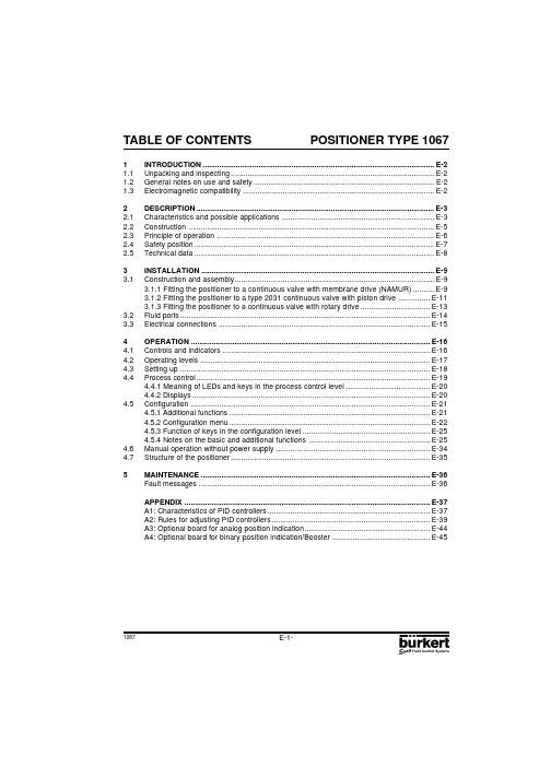
1067POSITIONER TYPE 1067E-1-TABLE OF CONTENTS1INTRODUCTION................................................................................................................E-2 1.1Unpacking and inspecting..................................................................................................E-2 1.2General notes on use and safety.......................................................................................E-2 1.3Electromagnetic compatibility............................................................................................E-22DESCRIPTION...................................................................................................................E-3 2.1Characteristics and possible applications.........................................................................E-3 2.2Construction.......................................................................................................................E-5 2.3Principle of operation.........................................................................................................E-6 2.4Safety position....................................................................................................................E-7 2.5Technical data....................................................................................................................E-83INSTALLATION.................................................................................................................E-9 3.1Construction and assembly................................................................................................E-93.1.1 Fitting the positioner to a continuous valve with membrane drive (NAMUR)..........E-93.1.2 Fitting the positioner to a type 2031 continuous valve with piston drive...............E-113.1.3 Fitting the positioner to a continuous valve with rotary drive.................................E-13 3.2Fluid ports.........................................................................................................................E-14 3.3Electrical connections......................................................................................................E-15 4OPERATION....................................................................................................................E-164.1Controls and indicators....................................................................................................E-16 4.2Operating levels...............................................................................................................E-17 4.3Setting up.........................................................................................................................E-18 4.4Process control.................................................................................................................E-194.4.1 Meaning of LEDs and keys in the process control level........................................E-204.4.2 Displays...................................................................................................................E-20 4.5Configuration....................................................................................................................E-214.5.1 Additional functions.................................................................................................E-214.5.2 Configuration menu.................................................................................................E-224.5.3 Function of keys in the configuration level.............................................................E-254.5.4 Notes on the basic and additional functions..........................................................E-25 4.6Manual operation without power supply..........................................................................E-34 4.7Structure of the positioner................................................................................................E-35 5MAINTENANCE...............................................................................................................E-36 Fault messages................................................................................................................E-36APPENDIX.......................................................................................................................E-37 A1: Characteristics of PID controllers..............................................................................E-37 A2: Rules for adjusting PID controllers............................................................................E-39 A3: Optional board for analog position indication............................................................E-44 A4: Optional board for binary position indication/Booster...............................................E-45E-2-1067POSITIONER TYPE 10671 INTRODUCTIONDear Customer,We congratulate you on the purchase of our positioner type 1067. You have made a good choice. To be able to make the best use of the many advantages the product has to offer, it is absolutely necessary to follow our advice and READ THESE OPERATING INSTRUC-TIONS CAREFULLY BEFORE FITTING THE UNIT AND PUTTING IT INTO SERVICE1.1 Unpacking and inspecting Please check the delivery for completeness and transportation damage. The standard delivery includes:-1 Positioner 1067 Ref 642292A-1 Operating Instructions ManualIn the event of loss or damage please contact your Bürkert Subsidiary.1.2 General notes on use and safetyThis publication contains no warranty statement For this we refer to our general purchase and delivery conditions.To ensure proper functioning and a long life of the positioner, the user must observe these Operating Instructions as well as complying with the installation conditions and permissible data as given in the data sheet. Installation and maintenance personnel must have training and qualifications suitable for the task.Suitable measures are to be taken to prevent unintentional actuation and the resulting effect on the process. Safe electrical isolating and shut-off devices for the media must be provided for the installation task. If the positioner is part of a complex automated system, a defined and controlled restart of the automated system after an interruption shall be guaranteed in accordance with the instructions.The accident and prevention safety regulations for electrical equipment shall be complied with during the operation, servicing and repair of the positioner.Repairs may only be carried out by authorised trained personnel.This symbol is shown in the OperatingInstructions each time particular careis required to ensure correctinstallation, functioning and operating safety of the equipment.1.3 Electromagnetic compatibility This device conforms to the EMC-Directive of the Council of European Communities 89/336/EEC.In order to comply with this directive, the wiring instructions must be followed.Master codeUnauthorised operation can be prevented at the various operating levels by a freely-selectable user code. Independent of this, there is a fixed, programmed master code which cannot be changed, by means of which all operations can be performed. This four-digit master code is given on the bottom margin of this page. It can be cut out and kept separately from these Operating Instructions.Master code:6568!1067POSITIONER TYPE 1067E-3-2 DESCRIPTION2.1Characteristics and possible applications (overview)The type 1067 positioner is an electropneumatic position controller for pneumatically actuated continuous valves. The device includes the following main functional groups: a feedback/positional transducer, an electropneumatic system and a microprocessor electronic system. The feedback/ positional transducer measures the actual position of the continuous valve. The microprocessor electronic system continuously compares the actual position (actual value) with a desired position value that was preset via the standard signal input and supplies the result to the position controller. If an error exists, the electropneumatic system causes the actual position to be appropriately corrected. The type 1067 positioner can be fitted to various continuous valves (e.g. valves with piston, membrane or rotary drives and with single or double action). Two variant forms of the basic device are offered that differ in their fixing options and feedback/positional transducers. In variant 1, an internal feedback/ positional transducer is used that takes the form of a rotary potentiometer. In variant 2, an external linear potentiometer serves as feedback/positional transducer.The positioner also implements a PID controller by means of which, in addition to position control, process control (e.g. level, pressure, flow or temperature control) can be achieved in the form of sequence control.A liquid-crystal display and a keypad with three keys are provided for operating the positioner. An operating concept with the following graded operating levels has been implemented:- Process operationThis level allows switching between automatic and manual operation, and enables manual actuation. - ConfigurationConfiguration level is used to specify certain basic functions when the positioner is taken into service and, if necessary, to configure additional functions.E-4-1067POSITIONER TYPE 10672 DESCRIPTIONFig. 1 Block diagram of the type 1067 positionerPositioner type 1067Input for process actual value4...20 mAInput for position or process setpoint0...10 V 0...20 mA 4...20 mA 24 VDCBinary input (contact)Analog output (option)RS 232 (option)RS 485 / PROFIBUS (option)OperationCharacteristics, functionsI n p u t sP o w e rO u t p u tI n t e r f a c e sPosition controller with additional functions, e. g.- close tight function - plug travel limitation - setting speed limitation - split range- correction characteristics - deadband- safety positionAdditional integrated processcontroller with the following features:- adjustable parameters - scalable inputs- setpoint setting via input signal or keysAutomatic adaptation of position controller to the continuous valve in useHierarchical operating concept for simple, staged-level operation1067POSITIONER TYPE 1067E-5-2 DESCRIPTION2.2 ConstructionThe positioner consists of the following main assemblies:- Body and bonnet (aluminium)- internal feedback/positional transducer for measuring valve position - Microprocessor/electronic unit for signal processing and control - Solenoid valves for control of a continuous action valve - Fluid plate with fluid ports - Terminals and cable glands - Display and keyboardFig. 2 Cross section of the positioner with internal feedback/positional transducerConnection terminalManual operationCable glandDisplay and keypadFluid plateFluid portsSolenoid valveAluminium body and bonnet with hingeElectronicIn variant 2, an external linear potentiometer serves as feedback/positional transducer (see fig. 3).Fig. 3 External feedback/positional transducerPositionaltransducer shaftInternal feedback/positional transducer for connection according to NAMURE-6-1067POSITIONER TYPE 10672 DESCRIPTION2.3 Principle of operationFig. 4 shows a operational diagram of the positioner with its relationship to a piston drive control valve.An external feedback/positional transducer is used in this case to measure the actual position.Fig. 4 Operational diagramPiston valveAir inlet Solenoid valvesAir exhaustPositioncontrollerSetposition Process value (Pressure, flow, level...)SensorProcess controllerThe position (actual position) of the valve drive is determined by the feedback/positional transducer.The signal corresponding to the actual position is continuously compared in the positioner with the desired position and the error (control deviation) is formed. Pulses of variable duration corresponding to the error are delivered to the magnetic valves of the electropneumatic system, by means of which the supplied air and outgoing air for positioning the actuating drive of a continuous valve are controlled.The desired position can be preset either via a standard signal input from outside (e.g. manually or via an external controller) or via the internal process controller. In the latter case, the desired process value is applied to the standard signal input or entered via keypad and a comparison is made with the process quantity (e.g. flow, pressure, level or temperature) that is to be controlled (Fig. 4).If the desired position is preset externally via the standard signal input provided for that purpose (i.e.if the internal process controller is not used), the device works as a position controller only (Fig. 5).The position controller is implemented as a PD controller within the microprocessor. A pulse-width modulation (PWM) member is connected to the controller output and, via its B 1 and E 1 outputs, the magnetic valves for supplying air to and venting the actuating drive are controlled. When a positive error exists, pulses (PWM signals) are output from output B 1 to switch the supplied air. When a negative error exists, pulses are output from output E 1 to switch the outgoing air.The positioner can be supplied for both single-acting and double-acting actuating drives. The PWM member has two further outputs, B 2 and E 2, via which the two additional magnetic valves for supplying air to and evacuating air from double-acting actuating drives are controlled.If the internal process controller is used, it constitutes a component in a higher-level control loop (main control loop). The position controller mentioned above now operates in a lower-level auxiliary control loop. The overall effect is sequence control (Fig. 6). The internal process controller (main controller) is implemented as a PID controller (Z1 and Z2 representing disturbance variables).Feedback/positional transducerActual-position External setpointProcess setpoint1067POSITIONER TYPE 1067E-7-2 DESCRIPTIONFig. 5 Position controlPosition controller Valve actuatorPWM element Setposition Fig. 6 Process controlProcessAuxiliary control loopMain control loopSetposition 2.4 Safety positionIn the event of power failure, the functioning of the actuator ensures that a pre-determined end position is adopted (opened or closed by spring pressure).Process controllerPosition controller PWM-element Valve actuatorE-8-1067POSITIONER TYPE 10672 DESCRIPTION2.5 Technical dataElectrical data Power supply:24 VDC Power consumption:< 10 W Input for desired valueInput for setpoint for position or process control:- Unit signal 4 ... 20 mA - Unit signal 0 ... 20 mA - Unit signal 0 ... 10 VInput for process signal (in case of process control):- Unit signal 4 ... 20 mABinary input:Can be configured as a normally open or normallyclosed contact.Terminations: 1.5 mm 2 bolted terminalsTwo PG 9 screwed glandsPneumatic data Control medium:filtered compressed dry air, oiled or non-oiled Pressure range:0 ... 6 bar Air rates Inlet valve:23 Nl / min (1)Exhaust valve:25 Nl / min (1)Air consumption by unit in stable state:0 Nl / min Unions:G 1/8" internal thread (1)When pressure reduction from 6 to 5 barMechanical dataRegulation range of internal path-measuring system:lift turn: 10...80 mmrotary movement: 0...180°Regulation range of external path-measuring system:lift turn: 0...50 mm Process controller dataProportional correction value KP:0...99,99Reset time TN:0.5...999.9Rate time TV:0.0...999.9Operating point:0...100%Installation and operating data External dimensions of positioner :125 mm x 80 mm x 80 mm (W x H x D)Material of body:Aluminium, lacquered Material of the fluid plate:Aluminium, anodised Weight of positioner:Approx. 1 kg Degree of protection:IP 65Operating temperature:0 ... 60 °C1067POSITIONER TYPE 1067E-9-3 INSTALLATION3.1 Construction and assemblyThe type 1067 positioner can be fitted to various continuous valves. Depending on the valve type either variant 1, with an internal feedback/positional transducer (a rotary potentiometer) or variant 2,with an external feedback/positional transducer (a linear potentiometer) is used (see section 2.3).Main dimensions:Positioner External feedback/positional transducer Width:125 mmDiameter:approx. 65 mm Height:80 mm Height:approx. 95 (115) mmDepth:80 mm3.1.1 Fitting the positioner to a continuous valve with membrane drive (according to NAMUR)ArrangementIn the case of a continuous valve with membrane drive, device variant 1, with an internal feedback/positional transducer (a rotary potentiometer) should be used. The positioner is screwed on to what is termed the «lantern » of the membrane drive (Fig. 7). Transmission of the valve position to the internal feedback/positional transducer is achieved by means of a lever conforming to NAMUR (Fig. 8).AssemblyA mounting elbow (Fig. 10) is provided for assembling variant 1 of the positioner to a continuous valve with membrane drive (e.g. Type 265). The following steps should be carried out:Screw mounting elbow Ẅ to the positioner using 4 x M6 Ẅẖ screws.Fasten pin ẅ using washer Ẋ and nut ẋ to that position of the lever ẇ which corresponds with the desired lift (the lever is marked in mm of lift).Put lever ẇ with pin on to the path-sensor shaft of the positioner so that the marking on the shaft points towards the pin on the lever. Then screw lever tight with screw Ẍ. Fasten carrier Ẇ with cheese-head bolts ẉ to the lifting rod of the membrane valve.Fig. 7 Fitting to a type 265 continuous valve with membrane driveFig. 8 Rear view of positioner (variant 1) with leverE-10-1067POSITIONER TYPE 1067Fig. 9 Position of lever during assembly3 INSTALLATIONSet positioner, with the mounting elbow Ẅ screwed on to it, on the membrane drive so that the pin ẅ slots into the carrier Ẇ, the point of the lever runs parallel with the upper edge of the positioner (Fig. 9) and the rear side of the positioner runs parallel with the carrier Ẇ. Fasten the positioner to the membrane drive in this position as appropriate to the following variants:-In the case of membrane drives with pillar lanterns, fasten mounting elbow Ẅ with two U-bolts Ẉ,nuts ẄẆ and washers Ẅẅ to the appropriate pillar lantern (Fig. 10a).-In the case of membrane drives with cast lanterns, fasten mounting elbow Ẅ with one screw ẄẆ(Fig. 10b) or four screws ẄẆ (Fig. 10c) to the appropriate cast lantern (Fig. 10a).Fig. 10Assembly of positioner to a continuous valve with membrane driveParallel1067POSITIONER TYPE 1067E-11-Fig. 11 Fitting to a type 2031 continuousvalve with piston drive Fig. 12 Rear view of positioner (variant 2)AssemblyAssembly of variant 2 of the positioner to a type 2031 continuous valve with piston drive.A set of add-on parts (NAMUR adapter, Fig. 13) is provided for assembling variant 2 of the positioner to a piston valve (e.g. type 2031). It consists of a mounting plate Ẅ, two hollow bolts ẅ, three O-rings Ẇ and two cheese-head bolts M5 ẇ.To assemble the positioner on a type 2031 continuous valve with piston drive, the following steps should be carried out (Fig. 13):Place an O-ring Ẇ in the recess of the mounting plate Ẅ (drive side). In the case of a large version,place a second O-ring on the other side of the mounting plate.Put two cheese-head bolts M5 ẇ from the drive side through the 5-mm drillings in the mounting plate.Screw the preassembled mounting plate Ẅ to the two connection pieces of the valve drive with two hollow bolts ẅ so that the lower connection piece is sealed by the O-ring.Place an O-ring Ẇ in the groove on the reverse side of the positioner.Add the positioner to the mounting plate and screw it on with the two cheese-head bolts ẇ.Assembly of the external feedback/positional transducer to a type 2031 continuous valve with piston drive.To assemble the external feedback/positional transducer, the following steps should be carried out (Figs. 13 and 14):Check that an O-ring Ẇ has been put into the valve drive (top). Insert O-ring if necessary.3 INSTALLATION 3.1.2 Fitting the positioner to a type 2031 continuous valve with piston drive ArrangementIn the case of a continuous valve with piston drive, variant 2 with the external path-measuring system (Fig. 3) should be used. The positioner is placed on the valve and screwed to it (Figs. 11 and 12). The valve position is transmitted directly via the spring-mounted rod of the path-measuring system (the linear potentiometer).E-12-1067POSITIONER TYPE 1067Fig. 14 External feedback/positionaltransducer3 INSTALLATION Set of add-on parts forB ürkert piston drive (ø125)ẈẉSet path-measuring system directly on the drive from above. Great care must be taken to ensure that the spindle of the path-measuring system is seated on the spindle of the drive.Screw in the path-measuring system and secure with spanner.Loosen setscrew ẉ and turn feedback/positional transducer so that the cable outlet is in the desired position. Retighten setscrew.Unscrew lid of path-measuring system. Remove PG-threaded joint Ẉ from the housing of the path-measuring system. Lead the plug of the positioning cable Ẋ through and plug it into the housing of the path-measuring system (green to green, white to red, brown to yellow). Draw surplus cable inwards, tighten PG threaded joint. Screw lid back on (O-rings).Fig. 13Diagram for the assembly of positioner and external path-measuring system to a Type 2031 continuous valve with piston drive (conforming to NAMUR)1067POSITIONER TYPE 1067E-13-Fig. 15Fitting to a continuous valve withrotary drive Fig. 16Reverse side of positioner (variant 1)with securing holes3 INSTALLATION AssemblyA coupling (adapter) Ẅ is provided for assembling variant 1 of the positioner on to a continuous valve with a rotary or part-turn valve actuating drive (e.g. Type 3210, Fig. 17). In addition, an assembly clip Ẇ (Fig. 18) is required and can be obtained from the manufacturer of the part-turn valve actuating drive. (It is normally used for the assembly of a limit-switch box).To assemble, the following steps should be carried out (Fig. 18):Secure the assembly clip Ẇ to the valve drive.Place the coupling Ẅ on the shaft of the positioner ’s feedback/positional transducer. The setscrew ẅ on the coupling should first have been slightly withdrawn.Place the positioner on the assembly clip. Ensure that the flat piece of the coupling fits into the slot in the end of the drive shaft.Secure the positioner on the assembly clip with 4 x M6 screws.Fix the coupling to the shaft of the feedback/positional transducer by screwing in the setscrew ẅ.If after the AUTOTUNE function is started the message TURN POT is displayed on the LCD, the setscrew must be loosened and the shaft of the path-measuring system rotated 180° relative to the drive. The setscrew should then be screwed tight and the AUTOTUNE function repeated.3.1.3 Fitting the positioner to a continuous valve with rotary driveArrangementIn the case of a continuous valve with rotary or part-turn valve actuating drive, variant 1 with an internal feedback/positional transducer should be used. Its shaft is coupled to the valve rotary drive (e.g. flap valve). The position of the rotary drive is thus transmitted directly to the shaft of the feedback/positional transducer.E-14-1067POSITIONER TYPE 10673 INSTALLATIONFig. 17Coupling for continuous valve withrotary drive Fig. 18Assembly of positioner on to a continuous valve with rotary driveContinuous valve with rotary driveSingle acting Double acting Single acting, parallel(for higher flow)3.2 Fluid portsConnect P port with compressed air supply (6 bar max.)1067POSITIONER TYPE 1067E-15-3 INSTALLATION3.3 Electrical connectionsFig. 20 Assignment of terminals Input U1 (unit signal 0 ... 10 V):Input resistance 200 k ΩInput I1 (unit signal 0/4 ... 20mA):Input resistance < 175 ΩInput I2 (unit signal 4 ... 20mA):Input resistance < 175 ΩCaution : The PE terminal must be connected to a ground point using the shortest possible cable (max. 30 cm) to ensure electromagnetic compatibility (EMC).Signal input:- either for valve position control- or for processregulation controlBinary inputContactOutput(Option)Power SupplyInput for processregulationE-16-1067POSITIONER TYPE 10674 OPERATION4.1 Controls and indicatorsAUTOTUNE…Arrow up“ key…Arrow down“ key MANUAL/AUTOMATIC keyLED4.2 Operating levels2 operating levels are provided for operation of the positioner:1° Process operation levelThis level, which is automatically set each time the unit is switched on, allows to change over between the MANUAL and AUTOMATIC operating modes. In the MANUAL mode the valve can be opened or closed by operating the …arrow keys“.2° Configuration levelThe purpose of the configuration level is to enable the basic functions to be specified on initial commissioning and additional functions to be configured as required.Each time the power is switched on, the positioner is in the process operation level in the AUTOMATIC mode. A changeover to the MANUAL mode can be accomplished using the MANUAL/AUTOMATIC key (cf § 4.4). From the process operation level it is possible to change over to the configuration level by pressing the MANUAL/AUTOMATIC key and holding for 5 seconds.1067POSITIONER TYPE 1067 E-17-4 OPERATION4.3 Setting upThe following basic settings are to be carried out on the initial setting up (commissioning) of the positioner in conjunction with the 2632 angle-seat control valves (specification of basic functions): -Specification of the positional feedback of the continuous valve to the positional transducer (direct or lever),-Specification of the unit signal input chosen for entering the set position (0 ... 20 mA, 4 ... 20 mA or 0 ... 10 V),-Initiating the automatic adaptation of the actuator to the valve being used.When the power is switched on, the positioner is in the process control level. It is necessary to switch to the configuration level for specification of the basic functions. To do this, press the MANUAL/ AUTOMATIC key and hold for 5 seconds. The first menu point X-SENS of the main menu is then displayed.Fig. 21 Main menu for first setting upFunctionAUTOMATICorMANUALafter 30 to 120 sec.BLINKINGE-18-1067POSITIONER TYPE 10674 OPERATIONTo perform a setting within the X-SENS and INPUT menu items, briefly press the MANUAL/ AUTOMATIC key again. One of the menu sub-items then appears in the display. It is possible to switch back and forwards between these sub-items, each of which describes a possible setting, by again pressing the arrow keys. The actual setting is carried out by pressing the MANUAL/ AUTOMATIC key on the selected menu sub-item.Fig. 22 Signification of the menu options in the main menuBasic function Associated settingsX-SENS Type of information transfer between the actuator and travel measuringsystem (factory-set to DIRECT)- DIRECT- Linear relationship- LEVER- Sinusoidal relationship (use of a lever)INPUT Specification of selected unit signals- 4 ... 20 MA- Unit signal current 4 ... 20 mA- 0 ... 20 MA- Unit signal current 0 ... 20 mA- 0 ... 10 V- Unit signal voltage 0 ... 10 VADDFUNCT Configuration of additional functionsAUTOTUNE Actuation of automatic adaptation of the actuator to the valveEND End of menuUnder the menu option X-SENS, indicate whether the mechanical transmission of path information from the positioner to the feedback/positional transducer is based on a linear or sinusoidal relationship.A sinusoidal relationship results if the lever mechanism is used for the transmission of path information (cf. section 3.1.1). In this event, when LEVER is confirmed an internal linearization takes place by means of an approximated sinusoidal function.The ADDFUNCT menu item can be skipped on the initial setting up. It is used only to configure additional functions.The AUTOTUNE menu item is used to start the programme for automatic parametering of the positioner. This automatically triggers the following functions:-Matching the sensor signal to the (physical) stroke of the control valve used.-Determining parameters of PWM signals for control of the internal solenoid valves.-Optimum adjustment of the control parameters of the position controller (target function: fastest possible movement to the set position without hunting).The programme for automatic parametering is started by setting the AUTOTUNE menu item in the main menu and then pressing the MANUAL/AUTOMATIC key and holding for 5 seconds. TUNE is displayed with a countdown from 5 to 0. The word AUTOTUNE then flashes for approximately 30 to 120 seconds (depending on the actuator volume). After the flashing ends, the message TUNE END is displayed.Note: In case of complete delivery of a valve fitted with a positioner, the AUTOTUNE function has already been run through in factory. In order to obtain the best accuracy, it is recommended to run the AUTOTUNE function once more before putting the valve in operation.If it is not possible to fully complete the AUTOTUNE routine, an error message is displayed (refer to the list of error messages in part 5).。
Burkert阀门手册说明书

宝德1067定位器中文
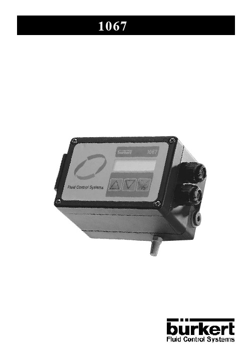
定位器操作手册1067型定位器目 录1引方 (2)1.1拆箱与检验 (2)1.2有关使用和安全方面的注意事项 (2)1.3电磁兼容性 (2)2说明 (3)2.1特性和可能的应用场合 (3)2.2结构 (5)2.3工作原理 (6)2.4安全位置 (7)2.5技术参数 (8)3安装 (9)3.1结构和安装 (9)3.3.1将定位器安装到带膜片执行机构(NAMUR)的连续调节阀上 (9)3.3.2将定位器安装到带活塞执行机构的2031型连续调节阀上 (11)3.3.3将定位器安装到带旋转式执行机构的连续调节阀上 (13)3.2流体接口 (14)3.3电气连接 (15)4操作 (16)4.1控制与指示器 (16)4.2操作界面 (17)4.3设置 (18)4.4过程控制 (19)4.4.1过程控制界面中LED和各键的含义 (20)4.4.2显示器 (20)4.5组态 (21)4.5.1附加功能 (21)4.5.2组态菜单 (22)4.5.3组态界面中各键的功能 (25)4.5.4基本功能与附加功能注释 (25)4.6无电源时手动操作 (34)4.7定位器的结构 (35)5维护 (36)出错信息 (36)1.1拆箱与检验请检查产品的完整性和无运输损坏参考号642292A-1操作手册1.2有关使用和安全方面的注 意事项本手册不包括任何保证条款为确保本定位器正常的功能和较长的寿命安装条件以及Data Sheet中给出的参数允许值应采取一些措施以防止因非故意行为而导致的对工艺的影响如定位器作为复杂控制系统的一部分操作只能由授权的经过培训的人员进行维修为了更好地发挥本产品所具有的许多优点维护和维修本定位器请仔细阅读本手册产品功能和使用安全要引起特别注意为符合该规范主机密码通过设置一个可自由选择的用户密码此外编好程的该4位主机密码在本页的底边给出主机密码:65682.1特性和可能的应用场合(概论)1067型定位器是用于气动连续调节阀的电气位置控制器一个电气系统和一个微处理器电子系统微处理器电子系统连续地将实际位置(实际值)与所需位置值(该值已由标准信号输入进行预设置)进行比较并将其结果输给位置控制器电气系统即修正实际位置膜片和旋转式执行机构的阀门和单作用或双作用阀门)Æä¹Ì¶¨·½Ê½ºÍ·´À¡/位置传感器不同采用旋转式电位计以外部线性电位器作为反馈/位置传感器除了位置控制外压力一个液晶显示器和三个键的键盘用于操作定位器并可通过手动驱动阀门如有必要图1 1067型定位器方块图位置控制器可选的附加功能分级界面操作特性0...10 V0...20 mA4...20 mA4...20 mA2.2结构定位器包括下列主要部件:-阀体和阀帽(铝)-测量阀位的内部反馈/位置传感器-处理和控制信号的微处理器/电子部件-控制连续阀的电磁阀-带流体接口的流体板-接线端子和电缆接头-显示器和键盘图2 带内部反馈/位置传感器的定位器剖面图带铰链铝质阀体和阀帽电子部件显示器和键盘手动操作连接端子电缆接头流体板流体接口电磁阀位置传感器轴内部反馈 /位置传感器NAMUR 接口图3 外部反馈/位置传感器在组合2中2.3工作原理图4为带活塞驱动连续调节阀的定位器的工作原理图图4 工作原理图阀的实际位置由反馈/位置传感器测得对应于偏差通过该脉冲控制用于定位连续阀的执行机构的进气和排气由内部过程控制器决定时并与被控制的实际过程值(如流量液位或温度)相比较(图4)1067就仅作为位置控制器(图5)Âö¿íµ÷ÖÆÆ÷½ÓÔÚ¿ØÖÆÆ÷µÄÊä³ö¶Ë控制电磁阀进气或排气存在正偏差时存在负偏差时该定位器既可用于单作用执行机构也可用于双作用执行机构可控制双作用执行机构的另外两个电磁阀它就成为主控制回路的一部分整个系统为连续控制(图6)反馈/位置传感器位置控制器过程控制器实际位置电磁阀传感器进气排气过程值(压力液位...)设定位置外部设定值过程设定值活塞阀图5位置控制图6过程控制2.4安全位置电源故障时2.5技术参数电气参数电源:功耗:所需值输入输入设定值用于位置或过程控制:过程信号输入(过程控制时):二进制输入:接线端子:气动参数控制介质:压力范围:空气流量进气阀:排气阀:稳态下空气消耗:接口:(1)当压力从6 bar降至5 bar时机械参数内部行程测量系统调节范围:外部行程测量调节范围:过程控制器参数比例调整值KP:复位时间TN:比率时间TV:起始操作点:安装和工作参数定位器外型尺寸:定位器材质:流体板材质:定位器重量:防护等级:工作温度:24 VDC<10W-标准信号 4...20 mA-标准信号 4...20 mA-标准信号 4...10 V-标准信号 4...20 mA可配置为常开或常闭触点1.5mm2端子两个PG9螺纹接头过滤润滑的或非润滑的0...6bar23Nl/min(1)25Nl/min(1)0Nl/min(1)G1/8上升:0...50mm0...99,990.5...999,90.0...99,90...100%125mmx80mmx80mm(WxHxD)铝阳极化处理过的Approx.1kgIP 650 (60)1067型定位器3安装3.1结构和装配1067型定位器可安装在各种连续调节阀上可采用带内部反馈/位置传感器(旋转电电位计)的组合13.1.1将定位器安装到带薄膜执行机构的连续调节阀(NAMUR接口)上配置配带薄膜执行机构的连续调节阀时定位器拧在膜片执行机构的<<lantern>>上(图7)aprox.65mm approx.95(115)mm主要尺寸:定位器宽度:高度:深度:125mm 80mm 80mm外部反馈/位置传感器直径:高度:图7安装到265型带薄膜执行机构的连续调节阀上安装安装弯管(图 10)用来将组合1的定位器安装到薄膜执行机构的连续调节阀(如 265型)上用垫圈7和螺钉8将销钉2固定在NAMUR 杆4的位置上将杆4和销钉放在定位器位置传感器的轴上然后用螺钉9固定杆图8 带NAMUR杆定位器后视图图9安装中杆的位置Parallel将带安装弯管1的定位器安装到薄膜执行机构上杆针与定位器的上边平行运动(图9)而定位器的后边与托架3平行运动用两个U形螺钉5-对于带管式lanterns的膜片执行机构3.1.2将定位器安装到活塞执行机构的2031型连续调节阀上配置配活塞执行机构的连续调节阀时定位器放在阀上并拧紧(图11和图12)ͼ11 安装到2031型带活塞执行机构的连续调节阀上安装将组合2的定位器安装到2031型带活塞执行机构的连续调节阀上图13)用来将组合2定位器安装到活塞阀(如2031型)上两个螺钉2应按以下步骤将定位器安装到 2031型活塞阀上(图 13):将一个O 型圈3放在安装板1驱动面的凹处将两个M5圆头螺钉4从驱动面穿到安装面这样下面的连接件即由O 型圈密封将定位器放在安装板上并用两个圆头螺钉4拧紧按以下步骤安装外部反馈/位置传感器(图13和图14):检查阀门执行机构(顶部)有一个O 型圈3ͼ12定位器后视图(变型2)从上面直接将位置传感器装到执行机构上拧入位置传感器并用扳手固紧使电缆出口位于所需位置松开位置传感器的盖子取出位置电缆7的插座并将其插入传感器外壳中(绿线接绿线褐线接黄线)Å¡½ôPG螺纹接头图13定位器安装图及外部位置传感器与2031型带活塞执行机构(NAMUR接口)的连续调节阀的安装图图14外部反馈/位置传感器用于宝得活塞阀(3.1.3将定位器安装到旋转式执行机构的2031型连续调节上配置配旋转式或角行程执行机构的连续调节阀时它的轴与旋转式执行机构(如摇臂阀)配合图15 安装到旋转式执行机构的连续调节阀上安装连接器(适配器)1用来将组合1的定位器安装到旋转式或角行程执行机构(如3210型另外可通过角行程执行机构生产厂获得应按以下步骤进行安装(图18)½«Á¬½ÓÆ÷1放在定位器反馈/位置传感器的轴上将定位器放在安装夹上用4x M6螺钉将定位器固定在安装夹上如果AUTOTUNE 功能开始后必须松开安装螺钉并将位置传感器的轴旋转180然后再拧紧安装螺钉重新做AUTOTUN E´ø°²È«¿×图17用于旋转式换行机构的连接器图18 将定位器安装到旋转式执行机构的连续调节阀上3.2流体接口P 口接压缩空气源(最大6bar)带旋转式执行机构的连续调节阀单作用双作用单作用3.3电气连接图20接线柱配置注意:PE 端子必须用一根尽量短的电线(最长30c m)与一个接地点相连输入U1(0...10V)输入I1(0/4...20mA)输入I2(4...20mA)输入阻抗220k 输入阻抗<1754.1控制与显示器向上向下4.2操作界面这种定位器有两种操作界面:1ÏÔʾÆ÷×Ô¶¯½øÈë´Ë½çÃæÊÖ¶¯×Ô¶¯ÔÚģʽÏòÉϼü¿ÉÒÔ´ò¿ª»òÕ߹رշ§ÃÅ设置界面在此界面中对定位器的基本功能进行初始化定义附加功能每次通电时过程控制界面此时按动键可以切换到模式手动/自动就会切换为4.3设置图21主菜单初始设置定位器与2632型角座控制阀联接完成后4...20mA或者0...10V):-进行执行机构与受控制阀之间的初始化自动适配定位器自动进入过程控制界面手动/自动由过程控制界面切换到这时显示器显示的是主菜单第一项在X-SENS 项中线性正弦曲线如果采用杠杆式传输方式正弦曲线因此L E V E RADDFUNCT 项仅在需配置某些附加功能使用AUTOTUNE 项对定位器进行自动参数编辑它包括以下功能:-匹配传感器的信号与控制阀的行程要进行AUTOTUNEÈ»ºó°´×¡ÊÖ¶¯/自动键5秒钟TU NRËæºó³öÏÖÉÁ˸µÄ×Ö大约持续30至120秒(闪烁时间根据执行机构的容积不同)ÏÔʾAUTOTUNE为了获得最佳精度如果AUTOTUNE 不能顺利完成见流程图向上键选择要进行设置的主菜单手动/自动在子菜单中通过向下再按一下键即可确认图22 主菜单中各选项的含义基本功能X-SENS-DIRECT -LEVER INPUT-4...20mA -0...20mA -0...10V ADDFUNCT AUTOTUNE END相关设置执行机构与行程测量系统之间信息转换的关系(工厂设置DIRECT)-线性关系-正弦曲线关系输入信号的规格-电流信号4...20mA -电流信号0...20mA -电压信号0...10V 附加功能的设置执行机构与受控阀的自动适配菜单结束1067型定位器4操作4.4过程操作4.4.1在过程控制界面中LED 和各键的含义要退出设置界面的主菜单E N DÈ»ºó°´Ò»Ï¼üÈ·ÈϺó¼üÖеÄÂÌÉ«L ED 灯亮时表示:自动模式键中的绿色L ED 灯灭时表示:手动模式-按手动/自动键小于5秒钟手动自动-按手动/自键大于5秒钟-在模式下PC O N TR L S ET PO I N TI N T ER显示时上中的一个持续上键(小于可以改变显示向上-在手动模式下按键可以关闭执行机构上键可以在这两种显示之间转换会有下列显示:过程变量的实际值:PV -(-99.9...999.9)过程变量的期望(设定)值:SP -(-99.9...999.9)阀驱动的实际位置:XPOS -(0...100%)阀驱动的期望(设定)位置:WPOS -(0...100%)按下过程控制器有效如果在组态时定义附加功能时上键中的一个持续具体为:松手后此时通过键可改变其大小;然后按键确认重复同样的操作四位数全部确认后显示执行机构的实际位置:XPOS-(0...100%)ģʽϵÄÏÔʾ¹ý³Ì¿ØÖÆÆ÷ÎÞЧ在手动状态下将持续显示实际过程值:PV -(-99.9...999.9)按住下并显示实际位置值:X P O S-(0...100%)当松开按着的键时手动模式的转换通过键实现如果按住向上键动作停止如果按住向下键如果在按住一个向上或向下键的同时可以使阀快速向先按的键所代表的方向动作都可以按键进入组态界面4.5组态4.5.1附加功能定位器的操作有严格的基本功能和附加功能区分通过设置这些功能如有近一步的位置或过程控制需求下表为附加功能列表图24附加功能附加功能 参数ACTUATE-SINGLEINTERNBOOST-DOUBLE CHARACT-LINEAR-1:25-1:50-25:1-50:1-FREE DEADBND-DBD CLTIGHT-CLT DIRECTN WPOS-RISE-FALLXPOS-RISE-FALL SPLTRNG-MIN-XMAX 描述执行机构功能单作用执行机构带外部增压阀-双作用执行机构选择输入信号和行程之间的转换特性曲线(校正特性曲线) -线性特性曲线-等比率特性曲线:1:25-等比率特性曲线:1:50-反向等比率特性曲线:25:1-反向等比率特性曲线:50:1-用户定义以%表示-设定输入信号的最大值二进制输入开4.5.2组态菜单由过程控制界面按住键5秒钟它由主菜单和附加功能菜单组成可以通过主菜单中的项进入如果需要通过选择附加菜单中的附加功能实现首先选择主菜单中的项手动/自动通过下然后按键确认同时会被扩展进主菜单中EN DFUN CT²¢·µ»ØÀ©Õ¹ºóµÄÖ÷²Ëµ¥²¢¿ÉÒÔ½øÐÐÉèÖÃÓëÓ¦ÓÃÐèÒªÔÙ½øÈë项按键*È»ºóÍ˳ö¸½¼Ó¹¦Äܲ˵¥¼´¿É°´Ï°´¼ü½øÐÐˮƽ·½ÏòÑ¡Ôñ°´Ï°´¼üSelection of item ADDFUNCTAdditional menuExpanded main menuReturn to expanded main menuConfirmation of selected additional functions for importation in main menuMain menuConfirmation of selected item图26 完整的组态菜单X-SENS DIRECT LEVERINPUT 4...20MA 0...20MA 0 (10V)ACTUATE DOUBLECHARACTLINEAR 1/251/5025/150/1FREE5100DEADBNDDBDCLTIGHT CLTDIRECTN WPOS XPOS ENDRISE FALLRISE FALLSPLTRNG MIN MAXX-LIMIT X-MIN X-MAXPCONTRL SETPOINT PARAM SCALE INTERN EXTERNKP TN TV X0X-TIMEOPN FAST OPN SLOWCLS FAST CLS SLOWSINGLE INTERN BOOSTENDDBDPV-H SP-L SP-HPV-L DP BIN-ININACTIVE SAFEPOSSPOS NORM OPN NORM CLSADDFUNCT AUTOTUNE ENDAOUTPUT BINARY CODE ANALOG NORM CLSXDXDONORM OPN BOOSTCODE MENU+M/A MENU4.5.3组态界面中各键的功能键:-向上滚动选择菜单选项-在菜单选项中增加数字值键:-向下滚动选择菜单选项-在菜单选项中减小数字值主菜单中使用键:-确认所选择的菜单项-确认设定值附加功能菜单中使用键:-确认所选择的附加功能项*¸ÃÏîÇ°标记将会消失4.5.4基本功能与附加功能注释X-SENS(工厂设定:DIRECT):阀的连续动作与行程测量系统之间信息转换类型其反馈信号与阀实际位置是线性关系D I R E C TLEVER:阀位与测量系统输入信号之间为正弦关系例如:Ty pe265带内部反馈/旋转电位计选项:40mA:输入信号类型为4...20mA00mA:输入信号类型为0...20mA00V:输入信号类型为0 (10V)图27 校正特性曲线ACTUATE (工厂设定:SINGLE,INTERN):阀执行机构的工作方式不带增压阀带增压阀CHRACT (工厂设定:LINEAR):用户指定的特性:该附加功能使用户可以选择一个阀门设定值(设定位置)和阀行程关系的转换特性曲线以Kv 值关于阀行程的关系表示一般有两种流量特性曲线:线性和等百分比相等的阀行程变化d s 产生相等的k v 值变化d K v(dKv=n lin ds)·§Ðг̱仯ds 对应于Kv 值的等百分比变化(dKv/Kv=n percent ds)¸ÃÇúÏßÒ²ÊܹܵÀÒò¶ø»áÆ«ÀëÁ÷Á¿ÌØÐÔÇúÏßͨ³£ÐèÌá³ö¶Ô¹¤×÷ÌØÐÔÇúÏß(如线性)的特殊要求有时需采用适当的方法来校正工作特性曲线1067定位器提供了具有多种特性曲线的转换元件可以设置一种线性和多种等百分比特性的曲线1:5050:1(参见2.7)»¹¾ßÓпÉ×ÔÓɱà³ÌµÄÌØÐÔÇúÏß¿É×ÔÓɱà³ÌµÄÌØÐÔÇúÏßSet positionP l u g t r a v e l自由编程的特性曲线的输入特性曲线是将设定范围按0...100%等分为21个间隔为5%的设定点而定义的但相邻两个设定点之间的行程差不能超过20%Ê×ÏÈÑ¡µ½F R E E子项手动/自动在它后面就是行程值为0(%)ϼü´Ó0至100%之间设定手动/自动而下一个设定点将会显示程序返回到CH AR AC T菜单图28编程设定的特性曲线示例Plug travel (%)Unit signal (%) Set position (%)Plug travel (%)Input with "Arrow" keysRestart pointDEADBND(工厂设定:DBD=0.5%):系统偏差的死区只有在系统偏差超过特定的死区范围时它能有效地保护伺服原理工作的阀最小由定义该功能使阀在控制范围以外关闭完全充满定义为100%设定范围:0.0...10%(如图30)图32 将一种信号范围分成2段设定范围DIRECTN (工厂设定:WPOS=RISE. XPOS=RISE):动作的方向XPOS 定义为:实际位置值和执行器AI 口供气状态之间的动作方向MAX=100%):范围分段0...20mA选用来控制一或多个定位器图31 动作方向1067型定位器4操作Input DIRECTN Setpoint WPOSI1U1(WPOS)0/4 mA 0 V RISE 0 %20 mA 10 V 100 %0/4 mA 0 V FALL 100 %20 mA10 V0 %Air supply DIRECTN Measure State A1XPOS (XPOS)Air exhaust RISE 0 %Air on100 %Air exhaust FALL 100 %Air on0 %0/4 mA Input signal20 mA0 V10 V air exhaustair onAir supply stateFALLRISEFALLRISESetpoint (mA)Setpoint rangepositioner 1Setpoint range positioner 2Plug travel (%)选项:OPN FAST:以最快速度打开阀;OPN SLOW:阀门打开时限速CLS FAST:以最快速度关闭阀CLS SLOW:阀门关闭时限速PCONTRL(过程控制):过程控制器组态TV:(微分时间)设定范围:0.0...999.9(工厂设定:0)XO:(过程控制器的起始工作点)设定范围:0...100%(工厂设定:0%)DBD:过程控制器不响应范围(死区)设定范围:0.2...5%(工厂设定:0.5%)SC ALE:定义过程控制器的输入值范围过程控制器的比例系数(K P)与设定值的范围相关下键输入设定值)SP-H)PV-H)直接输入即可BIN-IN:(工厂设定:INCATIVE):二进制输入用于保护定位器不接受非法操作AU TO TU NR:自动调整1067型定位器4操作4.6无电源手动操作定位器中的电磁阀不需电源即可通过旋钮(红色)手动操作可操作这些旋钮图35手动操作使用旋钮的条件:-任何情况下都不能通电-必须有气源双作用执行机构中接到A2口的腔室进气双作用执行机构中接到A2口的腔室排气所有旋钮必须转到0位图36 1067型定位器流程图4.7定位器结构1067型定位器4操作1067型定位器5维护出错信息通电状态的出错信息无法处理AUTOTUNE功能时的出错信息1067型定位器。
burkert流量计设置方法(一)

burkert流量计设置方法(一)Burkert流量计设置1. 简介Burkert流量计是一种常用的工业计量仪器,广泛应用于各个领域。
正确设置流量计参数对于正常运行和精确测量至关重要。
本文将介绍多种方法来设置Burkert流量计。
2. 方法一:使用菜单设置1.连接Burkert流量计到电源和控制系统。
2.打开控制系统的菜单界面,选择相应的设置选项。
3.在设置界面中,输入所需的参数,例如流量范围、单位、报警值等。
4.确认设置并保存。
3. 方法二:使用PC软件设置1.将Burkert流量计连接到电脑,并安装相应的驱动程序和设置软件。
2.打开设置软件,选择连接到的流量计。
3.在软件界面中,根据需要进行参数设置,如校准、输出选项等。
4.确认设置并保存至流量计。
4. 方法三:使用模拟信号设置1.将Burkert流量计连接到相应的显示器或控制系统。
2.通过模拟信号输入设备,发送所需的参数值。
3.在显示器中或控制系统中,选择相应的设置菜单。
4.输入和调整参数值,以匹配发送的模拟信号。
5. 方法四:使用数字通信设置1.将Burkert流量计连接到数字通信网络,如Modbus或Profibus。
2.在控制系统中,使用相应的通信协议设置和调整参数。
3.通过控制系统发送命令和数值,以设置流量计的参数。
4.确认设置并保存。
6. 注意事项•在设置Burkert流量计之前,确保了解流量计的规格和功能,并参考相关的使用手册。
•某些设置可能需要专业人员或厂家的支持,请咨询专业人士。
•在设置过程中,确保按照正确的步骤操作,避免误操作带来的问题。
•对于重要的参数设置,建议进行校准和验证,以确保测量结果的准确性。
结论通过使用菜单设置、PC软件设置、模拟信号设置和数字通信设置等方法,我们可以方便地设置和调整Burkert流量计的参数。
根据实际需求和设备的特点,选择合适的设置方法非常重要。
在设置过程中,要遵循正确的步骤和注意事项,以确保流量计的正常运行和准确测量。
burkert流量计报警代码
burkert流量计报警代码
burkert流量计是一种常用的流量测量仪表,它可以测量液体、气体和蒸汽的
流量。
它的报警代码是用来提醒用户发生了异常情况,以便及时采取措施。
burkert流量计的报警代码有很多种,其中最常见的有:
1、E1:表示传感器故障,可能是由于传感器的损坏或连接不良导致的。
2、E2:表示传感器超出范围,可能是由于传感器的参数设置不当导致的。
3、E3:表示传感器输出不稳定,可能是由于传感器的温度变化或振动导致的。
4、E4:表示传感器输出超出范围,可能是由于传感器的参数设置不当导致的。
5、E5:表示传感器输出不正确,可能是由于传感器的损坏或连接不良导致的。
6、E6:表示传感器输出超出范围,可能是由于传感器的参数设置不当导致的。
7、E7:表示传感器输出不正确,可能是由于传感器的损坏或连接不良导致的。
当burkert流量计发出报警代码时,用户应该及时采取措施,检查传感器的连
接是否正常,检查传感器的参数设置是否正确,检查传感器的温度是否正常,以及检查传感器是否有损坏或连接不良的情况。
如果发现问题,应及时采取措施进行维修或更换。
总之,burkert流量计的报警代码是用来提醒用户发生了异常情况,以便及时
采取措施。
用户应该及时了解burkert流量计的报警代码,以便及时采取措施,保证流量计的正常使用。
- 1、下载文档前请自行甄别文档内容的完整性,平台不提供额外的编辑、内容补充、找答案等附加服务。
- 2、"仅部分预览"的文档,不可在线预览部分如存在完整性等问题,可反馈申请退款(可完整预览的文档不适用该条件!)。
- 3、如文档侵犯您的权益,请联系客服反馈,我们会尽快为您处理(人工客服工作时间:9:00-18:30)。
等待30— 120秒
THANK YOU!!!
• 让我们互相学习,构建美好未来!!
如果气源消失,阀门依靠弹簧复位
外部反馈/位置传 感器(上下动作)
Wet 破真空阀
电缆插座
外部反馈/位置传 感器 信号线
安装板
O型圈
1067定位器
执行器进气口
和定位器出气口 相连
阀门开度值由 PLC 4—20MA模 拟量信号给入
WET 真空混料破真空阀
执行器阀杆 外部反馈/位置传感器的滑块在上下滑动过程中松动\脱落 造成阀门 定位错误 产生报警
Positioner 1067 交流稿
手动/自动
电源 : 24VDC 气压0—6bar 1067 定位器分为两种 1:内部反馈/位置传感器 采用旋转电位计
2: 外部反馈/位置传感器 采用外部线性电位器 按5秒手动/自动 键进入 组态界面
Wet 真空混料 破真空阀
单作用
名词解释 单作用:气缸的移动通过仪表空气的压力,返回时由弹簧提供压力
Nucon 大料罐 放料阀
阀门 和执行 器连接处
内部反馈/位置传 感器 (转动)
双作用
名词解释
双作用:气缸的移动和返回都是通过仪表空气来提供动力。 单作用的扭矩要比双 作用的小得多。故双作用一般用于需要较大扭矩的阀门.如果两边气源同时切断 阀门将保持断气前的开度
定位器的主菜单项
• X-SENS
选择 direct
信号常开常闭输出 设定
阀门开度大于设 定值 输出信号
例如 :值设定为5 阀门关闭度大于 等于5信号输出 , 触发相关的程序 连锁,小于5不输
出
自动校正
பைடு நூலகம்
按5秒
完成校 正
校正前最好去除 外加信号 防止
信号干扰
1 . 进入主菜单 2 . 选AUTOTUNE 长按5秒 3. 等待30—120秒,在此过程中阀会 连续打开\关闭阀门几次.所以必须 充分考虑到阀门关闭打开的后果,
安装固定 板
连接轴顶 丝
顶丝处 为平面
执行器和位置 传感器连接轴
套
顶丝松动会造成 ,轴转过的角度和实际角度产生偏差.需要重新自动较正
定位器内部图
内部反馈/位 置传感器
阀的实际位置由内部反馈/位置传感器测得,通过电路脉冲控制电磁阀的通 断,从而控制执行机构的进气和排气。
NUCON定位器输出信号的设定
打*后
注意单作用 (intern) 双作用(double)
nucon定位器内部图
信号1
阀门开度 由PLC 4— 20MA信号
给定
排线接口容 易松动
信号2
红色圈内为OUTPUT 数 字输出板安装处 nucon
料罐选用
生产过程中不建议打开盖子,打开过程中排线易松动,会造成信号 断开,造成停产
NUCON定位器和执行器连接图
• INPUT
输入信号4—20MA
• ADDFUNCT
附加菜单 加*号选择功能
• AUTOTUNE
自动校正
END
出菜单
定位器ADDFUNCT 菜单
打*前
在进入到OUTPUT后, 按下 手自动键 前面会出现 * 字 代表被主菜单调用 , 如果 没有*字则output 下的所有
功能 定位器将不执行
万能密码6568