PdMTC_11006_08Jan2011_Bearing-Gearbox Faults_VI
汽车零部件编号规则 ( 修订稿)
Q/LFQ 力帆实业(集团)股份有限公司企业标准Q/LFQ J03.009.3-2014代替Q/LFQ J03.009.3-2009汽车零部件编号规则(送审稿)2014-XX-XX发布2014-XX-XX实施目次前言 (Ⅱ)1 范围 (1)2 规范性引用文件 (1)3 术语和定义 (1)4 汽车零部件编号 (1)5 产品特征代号 (4)附录A(规范性附录) (5)附录B(规范性附录) (31)Ⅰ前言本标准主要参照QC/T 265-2004《汽车零部件编号规则》本标准根据本企业汽车产品零部件的实际情况编写。
本标准与 Q/LF J03.009.3-2009 相比主要变化如下:—汽车零部件编号中的分组号进行了修改、增补;—修改了4.3.2条,4.3.3条的内容,修改为产品代码基本型A不省略;—修改了4.7条的内容,修改为变更代号第一次变更用A1不省略。
本标准按照GB/T 1.1-2009给出的规则起草。
本标准由力帆汽车研究院标准所提出。
本标准由力帆汽车研究院标准所归口。
本标准由力帆汽车研究院标准所所负责起草。
本标准起草:本标准批准:本标准所代替标准的历次发布情况为:1、Q/LFQC J02.4-20042、Q/LF J02.009.2-20053、Q/LF J02.009.2-20074、Q/LF J02.009.2-2009汽车零部件编号规则1范围本标准规定了本企业各汽车的辅助图号、总成和装置及零部件号的基本绘制和方法。
本标准适用于本企业各汽车的零件、总成和装置编号。
本标准不适用本企业各汽车所用标准件和轴承等的编号。
2规范性引用文件下列文件中的条款通过本标准的引用而成为本标准的条款。
凡是注日期的引用文件,其随后所有的修改单(不包括勘误的内容)或修订版均不适用于本标准,然后,鼓励根据本标准达成协议的各方研究是否可使用这些文件的最新版本。
凡是不注日期的引用文件,其最新版本适用于本标准。
QC/T265-2004汽车零部件编号规则3术语和定义下列术语和定义适用于本标准。
模具常用语中英文对照

weld
4.1。2加工说明对照表:
加工说明Machining Note
注:有0.00的地方为数据填入处
外导套OUTER GUIDE BUISHING起吊杆HANDING PIN
实数铣通MILL THRU正反两面各铣TOP SIDE AND OPP SIDE MILL
X:-¢0.00(氮气弹弓过孔,锣穿)单+0。00
X:—¢0。00(CNC C’BORE OPP SIDE FOR GAS SPRING,S+0.00,DP0。00)
X:—¢0。00(合销孔,铰)
X:—¢0。00(REAM FOR DOWEL)
X:—¢0.00(合销孔,割)单+0.00
X:-¢0.00(W/C FOR DOWEL) S+0。00
(正面沉头¢0.00*0。00深,内攻M0.00*1.5牙)
X:—M0。00钻穿,反面攻深0。00,有效牙0。00
X:—M0.00 DR.THRU, TAP DP0。00 OPP.SIDE,THR DP0.00)
X:-M0。00钻穿,正面攻深0.00,有效牙0.00
X:—M0.00 DR。THRU,TAP DP0。00 TOP SIDE, THR DP0.00)
拍平
flat
卷圆
curl
种类
中文名称
英文名称
中文名称
英文名称
工
序
类
旋转
rotate
铆接
rivet
产品切边线
trim line
铆螺母
stake nut
切断
cutoff
接刀口
mismatch
料带带料处
carrier tab
圆锥滚子轴承游隙设定的方法

设定合适的轴承游隙可以增加系统的刚度,例如,合适的游 隙可以让齿轮更好地接触,延长齿轮的寿命
轴承内圈和外圈可以分离,更容易安装
轴承的游隙在装配机器时设定,因此可以接受更宽的轴和轴 承座的公差范围
可以通过多种方法来快捷地设定圆锥滚子轴承的游隙。可 以手动设定游隙,预设游隙或自动设定游隙。五种常用的自动 设定游隙的方法(即SETRIGHTTM、ACRO-SETTM、PROJECTASETTM、TORQUE-SETTM 和 CLAMP-SETTM),每一种都有很多实 施方式、注意事项和优势。见表 1。
某些应用的安装游隙会被设定成预紧以提高承受高应力部 件的刚度或进行轴向定位,否则这些部件就会受到过度挠曲和 偏心的影响。
必须避免工作状态下的过度预紧,否则轴承的疲劳寿命会 显著缩短。另外,运行时过度预紧会产生大量热量,可能导致 润滑问题和轴承的过早损坏。
承载区是对滚道承载圆弧的物理计量,直接反应了承担载 荷的滚子数量。对于单列圆锥滚子轴承,最大寿命对应的承载 区大约为 225 度。图 2 用图示说明了轴承在(悬臂)齿轮轴上的 L10 寿命和工作游隙之间的关系。
对于复杂的、大型的或大批量生产的应用,手动设定游隙可 能太麻烦,不精确,不可靠或太费时。铁姆肯公司设计出了预设 游隙轴承组件和自动游隙设定方法,作为手动设定游隙的替代 方案。
6 圆锥滚子轴承游隙设定的方法
预设游隙轴承组件
预设游隙轴承组件
典型的预设游隙轴承组件的应用
很多应用使用或需要双列或紧密连接配对的轴承组件。这取 决于机器的设计和运行特点(如热增长的影响、高载荷等)。为 便于设定这种情况下的轴承游隙,我们经常使用预设游隙轴承 组件。预设游隙轴承组件具有各种形式。但大多数一般被称为带 隔圈轴承(图 4)。大多数预设游隙轴承在制造和供应时都带有隔 圈。隔圈根据轴承进行配磨定制,用于控制内部间隙(参考类型 2S 和 TDI)。因此,这些定制或“配磨”的隔圈无法与其他轴承 组装件互换使用。有一些预设游隙组件,如类型 SR 或 TNA,可 以允许使用可互换的隔圈和/或轴承部件。设计这些可互换组装 件部件的目的是为了更严格地控制影响轴承游隙的重要公差,因 此,这些部件可以随机选择使用。
倍福故障手册
6、厂家产品介绍6.1 倍福6.1.1CX1020介绍及故障处理方法6.1.1.1CX1020的型号标识CX1020的配置:6.1.1.2CX1020 CPU 性能指标6.1.1.3模块外观6.1.1.4电源模块与CPU的组装将模块安装到导轨上:a、在装到导轨之前将模块下白色锁紧机构拉下,使其不起作用。
(如下图)b、将模块后的卡槽对准导轨轻轻按下,然后推上白色紧锁机构,至此CPU和模块的机械安装完毕。
c、将模块安装到导轨上。
d、CF卡的安装方法6.1.1.5 CPU诊断初步——指示灯TC指示灯饿几种状态,直接反映了TwinCAT的运行状态。
(CX1020-0000)6.1.1.6 CPU 诊断初步——常见故障及处理6.1.1.7CX1100-00XX诊断介绍I/O Error指示灯在快速闪烁之后,第一次慢闪烁表示错误码,第二次慢闪烁为具体的出错信息。
诊断过程:例如:系统上电后,cx1100-0002 I/O error指示灯闪烁不停。
记录快速闪烁后的第一次慢次数对照上面诊断信息进行原因分析和出错处理。
6.1.2 I/O 模块介绍及故障处理方法6.1.2.1 KLL1104(1)模块介绍4通道输入端子模块额定电压24V DC 3.0ms滤波“0”信号电压-3V (5V)“1”信号电压15V (30V)(1)LED灯每一个数字量输入通道都有一个对应的LED灯。
如果该通道有输入,则该LED等变为绿色。
没有输入的时候,LED等不亮。
(3)诊断方法a、如果有输入信号,但是LED灯没有亮。
可能是LED灯坏了,也有可能是输入通道坏了。
b、检查该通道的输入信号电压是否在15V-30V之间。
c、检查TwinCAT System Manager中该通道的值。
如果电压不在15V-30V之间,并且TSM文件中钙通道的值为“1”。
则是LED灯坏了。
如果电压在15V-30V之间,并且TSM文件中该通道的值为“0”。
则是改通道硬件出了问题。
轴承工艺设计模块在PDM系统中的应用
关键词 : 滚动轴承 ; A P -艺设计 ; CP ; V 数据库
中圈分类号 :H133 ;P 9 . T 3 .3 T 3 17 文 献标 志码 : B 文章编号 :0 0— 7 2 20 ) 1 0 3 10 3 6 (0 8 1 — 06—0 3
1 轴 承 工 艺 设 计 ( A r 模 块 的 理 C P' )
管理功 能实现 对工 艺设 计结果 数据 的管理 。 ( ) 现典 型工 艺 的积累 和维护 。 4实 () 5 实现 工 艺 规 程 设 计 过 程 的可 视 化 , 自动
同锻工工 艺 设计 类 似 , 车磨 工 艺 、 热处 理 、 工 装 、 料定额 等 1 设计 向导主要从基 础数据 管 材 8个 理 库 中获得基 本 的设 计数 据 , 用计 算模 块 进 行 使 计算 并 使用 C D 出 图模 块 生成 C D 图纸 , A A 最后
完成计算过程 , 自动生成工艺卡片、 工序图等工艺
收 稿 日期 :0 8—0 0 ; 回 日期 : 0 0 2 20 4— 3 修 2 8— 4— 8 0
马
军 等 : 承 工 艺 设 计模 块 在 P M 系 统 中 的应 用 轴 D
・ 7・ 3
将 进耄参表 算 、D等 3轴 工 设 知 库 建 与 用 P 系 行篓数、 稿 A 用 承 艺 计 识 的 立 运 D统 管 设 M 理 计 C图
q 一 L一 ~ 一 ~ 。
。
所 有工艺 向导 的设计 完成都不 能脱 离完善 的 设计 知识 库 , 基 础数 据 库 的灵 活 应用 为轴 承 设计
轴承工 艺设 计 模块 采 用 全 向导式 设 计界 面 , 辅助 工艺设 计人 员 进行 轴 承 工艺 设计 开 发工 作 ,
博世柴油机标定界面

鲍麦克斯电控1
第二步:使用 键和 键修改对应的参数值(E 的值),设置范围:0-99 针。
第三步:设定完毕后踩下踏板即可开始缝纫。
3、四段缝
第一步:按下 键,在液晶显示区连续回缝图标 会亮,其余图标则不显示,表示 已经选择了四段缝模式。
第二步:使用 和 键修改对应的参数值(E、F、G、H 的值),设置范围:0-99 针。
1.3 功能操作
1.3.1 自由缝功能
按下 键,在液晶显示区自由缝模式图标 会亮,其余图标则不显示,表示已经选 择了自由缝模式,踩下踏板即可开始缝纫。
1.3.2 简易缝功能
进入系统员模式,将 P46 参数设为 1,则将操作工模式设置为简易缝模式。在简易缝 模式下,液晶仅显示自由缝和停车抬压脚图标(如果选择),且除了设定参数的相关按键 和加减速按键外,其余按键均无效。
备注:不管在何种缝纫模式下,剪线以后机头处于静止状态时按下该按钮均无效。
1.3.9 针迹补偿功能
针迹补偿功能的介绍以前固缝(A=B=4 针)为例,进行说明: { 如图 a 所示,将参数 P14 适当调大。
A段 B段 A段 B段
B 段第一针变短
A 段多一针,B 段少一针
图a
{ 如图 b 所示,将参数 P14 适当调小。
800~1200
500~2000
1000
800 为自动测试轮带比(显示在监控参 数 SP6);
第4页共8页
ms 千位数为翻抬开关设置 0XXX:为
翻抬开关选择,电机运行方向设 置及加减速变化量设置(直驱)
0-9999
1000
1088
常闭,1XXX:为常开;个位为减速变化 量,十位为加速变化量,0 为最快,9 为最
第2页共8页
6100系列传输带轮结束填充器套件说明书

6100 Series Conveyor Idler End Filler Kit Instructions SheetDorner Mfg. Corp.1851-501 Rev. AInstallation, Maintenance& Parts ManualInstallation1.Remove and discard tail screws (A of Figure 1).Figure 1A 2.Install square head bolt (B of Figure 2)in block (C)(Note orientation – block is not symmetrical).Figure 2BC3.Install block with square head bolt (D of Figure 3)with screw (E) to conveyor . Make sure edge of block(D) contacts head plate edge (F).4.Adjust square head bolt (G of Figure 4) to contactconveyor frame (H).Figure 4HG5.Repeat steps 1–4 for opposite side of conveyor.Belt Tensioning1.Follow belt tensioning procedure in 851–268 “6100Series End Drive Conveyors” manual.6100 Series Conveyor Idler End Filler Kit Instructions SheetDorner Mfg. Corp.2851-501 Rev. A2.Adjust square head bolt (G of Figure 5) to contactconveyor frame (H) on both sides of conveyor.Figure 5HGBelt Installation1.Remove screw and filler block (D of Figure 6) onboth sides of conveyor.Figure 6D2.Follow belt installation instructions in 851–268“6100 Series End Drive Conveyors ” manual.3.Install block with square head bolt (D of Figure 3)with screw (E) to conveyor . Make sure edge of block (D) contacts head plate edge (F).4.Adjust square head bolt (G of Figure 7) to contactconveyor frame (H).Figure 7HG5.Repeat steps 3 and 4 for opposite side of conveyor.Service PartsFigure 81.Block RH (694020)2.Block LH(694021)3.Square Head Bolt (807–1130)4.M5x16mm Screw(920593M)3124Dorner Mfg. Corp. reserves the right to change or discontinue products without notice. All products and。
NSK轴承型号大全
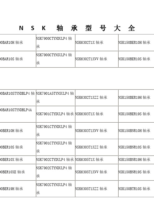
NSK100BTR10H轴承
NSK7905CTYNSULP4轴承
NSK65BAR10STYNDBLP4A轴承
NSK15TAC47B轴承
NSK100BTR10S轴承
NSK7906A5TYNSULP4轴承
NSK65BER10H轴承
NSK15TAC47BDBC10PN7A轴承
NSK100TAC03CMC轴承
NSK7906CTYDULP4轴承
NSK65BER10S轴承
NSK15TAC47BDFC10PN7A轴承
NSK100TAC20X+L轴承
NSK7906CTYNDULP4轴承
NSK65BER10X轴承
NSK15TAC47BSUC10PN7B轴承
NSK100TAC29X+L轴承
NSK105BNR19XE轴承
NSK7911CTYSULP4轴承
NSK65BTR10H轴承
NSK17TAC47B轴承
NSK105BTR10H轴承
NSK7912CTYNDULP4轴承
NSK65BTR10S轴承
NSK17TAC47BDBC10PN7A轴承
NSK105BTR10S轴承
NSK7912CTYNSULP4轴承
NSK170TAC20D+L轴承
NSK105BER19S轴承
NSK7908CTYNSULP4轴承
NSK65BNR10STYNDBLP4轴承
NSK170TAC29D+L轴承
NSK105BER19X轴承
NSK7909CTYDULP4轴承
NSK65BNR10STYNDUELP4轴承
NSK17BGR02H轴承
NSK7918CTYSULP4轴承
沃克夏发动机说明书

APPLICATION: Tractors: 77 Oliver Thru # 6502;WA-216-A 4/1/2004QTY ITEM # DESCRIPTION LETTERED ITEMSINCLUDED IN KIT1 994136 In-Frame Kit, 3.500" Overbore I1 994188 In-Frame Kit, 3.625" Overbore I1 995136 Out-of-Frame Kit, 3.500" Overbore O 1 995188 Out-of-Frame Kit, 3.625" Overbore O6 191197 Sleeve & Piston Assembly, 3.500" Overbore O I6 191195 Sleeve & Piston Assembly, 3.625" Overbore O I6 191192 Piston Assembly, 3.500" Overbore6 191193 Cylinder Liner, 3.500" Overbore (Includes O-Rings)6 191138 Cylinder Liner O-Ring Package1 191182 Block Repair Sleeve, Lower Liner Pilot Bore6 191194 Piston Ring Set, STD 3.312" Bore (3-1/8 1-1/4)6 191187 Piston Ring Set, 3.500" Overbore (3-1/8 1-3/16)6 191177 Piston Ring Set, 3.500" Overbore (3-1/8 1-1/4)6 191189 Piston Ring Set, 3.5625" Overbore (3-3/32 1-1/4)6 191191 Piston Ring Set, 3.5625" Overbore (3-1/8 1-1/4)6 191196 Piston Ring Set, 3.625" Overbore (3-3/32 1-3/16)1 191184 Piston Ring Set, 3.625" Overbore (3-3/32 1-1/4)1 191185 Piston Ring Set, 3.750" Overbore (3-3/32 1-1/4)6 191174 Piston Ring Set, 3.750" Overbore (3-1/8 1-3/16)1 191175 Piston Ring Set, 3.750" Overbore (3-1/8 1-1/4)6 291181 STD Rod Bearing O O I I6 291184 .003 Rod Bearing6 291182 .010 Rod Bearing6 291183 .020 Rod Bearing12 791134 Connecting Rod Shims, Used w/Early MS216 Rod Only1 291176 STD Main Bearing Set O O I I1 291177 010 Main Bearing Set1 291178 020 Main Bearing Set1 291179 030 Main Bearing Set1 391221 In-Frame Gasket Set I I1 391219 Head Gasket 6 391182 Intake Valve Seal (Rubber Q-Ring in Retainer Cup)9 391217 Manifold Gasket Set1 391212 Valve Cover Gasket (Cork)1 391222 Full Gasket Set w/Seals O O1 391159 Timing Cover Gasket1 391198 Pan Gasket1 391142 Front Crank Seal (Face Type) 1 391184 Front Pulley Felt Seal1 391147 Rear Crank Seal (Face Type)1 391148 Rear Lip Seal Conversion Kit(Hsg, Seal, Gkt, Bolts, Dowels)6 291147 Pin Bushing (1 Piece Bushing Upgrade)1 291148 Cam Bearing12 NLA Rod Bolt12 791131 Rod NutWA-216-A 4/1/2004 QTY ITEM #DESCRIPTIONLETTERED ITEMSINCLUDED IN KIT1999517 Cam KitC1 999114 Valve Train KitV1 591149 Camshaft (3/16" Key) C1 591124 Cam Key (3/16 X 1)1 591126 Cam Thrust Spring1 591127 Cam Thrust Button12 591123 Tappet C6 491213 Exhaust Valve V6 491214 Intake Valve V6 491188 Exhaust Valve Guide V6 491164 Intake Valve Guide V6 491147 Exhaust Valve Spring (Use Only w/Rotator) V6 491172 Intake Valve Spring V6 491148 Exhaust Valve Rotator V24 491149 Valve Keeper, Late (2 Lands) V12 491158 Valve Spring Cup (Needed When Replacing Flanged Guides)12 491193 Rocker Arm Bushing, Thru ESN 8682056 491153 LH Rocker Arm, After ESN 8682056 491154 RH Rocker Arm, After ESN 8682051 491198 Rocker Arm Shaft, After ESN 86820512 491169 Rocker Arm Adjusting Screw, After ESN 8682054 491139 Rocker Arm Shaft Spring1 591136 Cam Timing Gear (3/16" Key)1 591128 Crank Timing Gear12 591137 Push Rod1 691134 Oil Pump Assembly1 691129 Oil Pump Kit (2-Blades 1-Spring 1-Shaft 1-Gear 1-Hdw Pkg) 1 691131 Oil Pump Repair Kit (2-Blades 1-Spring)1 691132 Oil Pump Drive Gear1 691135 Oil Relief Valve Spring (1 9/16" Long)1 791132 Plug, Block/Cam (2" Flat Brass)1 791133 Plug, Block (1" Flat Brass) 1 791124 Plug, Oil Galley (21/32" Cup)7 791133 Plug, Cylinder Head (1" Flat Brass)1 291159 Governor Bushing, 1 1/8" OD (Front of Block)1 291161 Governor Bushing, 1 3/8" OD (Front of Block)1 291162 Governor Thrust Washer1 891151 New Water Pump (Cast# 190060, 190160, 190360)1 891155 New Water Pump (Cast# 180060, 180160)1 891148 Thermostat1 891142 Coolant Heater。
盾构机部件各英语词汇
盾构相关专业英语词汇词汇A部abnormal resistance 异常阻力abrasion resistant 耐磨性abrasion 磨损access 到达accumulator 蓄能器actual 实际的adopt 采用advance 推进agent 起泡母液agitator tank 搅拌罐air compressor 空气压缩机air conditioning 空调air filter unit 空气过滤装置air lock 气舱alignment control 线形控制allowable stress 容许应力angle 角度anti-corrosive paint 防锈漆anti-pressure seal 抗压密封appearance test 外观测试arching action effect 拱形效应articulate cylinder 铰接油缸articulation angle 铰接角度articulation jack 铰接千斤顶articulation stroke 铰接行程articulation system 铰接系统articulation 铰接assembling method K片组装方法assembling 组装automatic mode 自动模式automatic oil lubricating system 自动油脂润滑系统automatic 自动的auxiliary bit 保护切削刀头auxiliary cutter bit 辅助切削刀auxiliary pump 辅助泵axial 轴向的axis type screw conveyor 轴承螺旋输送机axis 轴词汇B部back filling injection device 壁后灌浆设备back filling injection 同步注入(背填)back grouting system 同步回填系统back up system 备份系统back-up gantry 支承架back-up pressure 备用压力balk head 隔板ball valve 球阀bar 巴(压强单位)baseline 基准线beam 梁bearing housing 轴承套bearing life 轴承寿命bearing roller 轴承滚轴bearing 轴承belt conveyor 带式输送机(传送带)bentonite 膨润土(皂土)blade 叶片bolt 螺杆bottom screw 底部螺旋机boundary condition 边界条件breasting plate 承冲板,面板brush packing 密封刷(注:packing 为填充) brush type tail seal 盾尾密封刷bulkhead 舱壁bull gear 大齿轮词汇C部cable reel电缆盘cable 电缆calibration 校验,标定cam switch 凸轮开关capacity 能力,运量casing I.D 螺旋输送机内径cavity 轴承腔center cutter 中央刀头center shaft radius 中心轴半径center shield 中盾chain hoist 链式葫芦circuit breaker 断路器(断路开关)clay layer 粘土层clay 粘土cleaning device 清洗装置clockwise and counterclockwise 顺时针和逆时针clogging 阻塞coefficient 系数cohesion 粘度,内聚力cohesive (土体)粘性coil 线圈compression system for man lock (regulator)人孔闸的压缩系统(调节阀) compression 压力compressor and slurry pumpcompressor 压缩机control cabin 控制室control circuit 控制电路control 控制cooling circuit 冷却回路copy cut device 仿形刀装置copy cutter 仿形刀(超挖刀)corrective operation 校正操作corresponding 相应的coupling 接头crack 断裂,破坏crane 起重机criterion 验收标准cross-sectional 截面积current 电流curvature 转弯段curve configuration 曲线轮廓curve radius 转弯半径,曲线半径curving performance 曲线段施工cutter bit 刀头cutter chamber 土仓cutter device 刀盘装置cutter driving unit 刀盘驱动单元cutter drum 刀盘滚筒cutter electric motorcutter head 刀盘cutter main sealing system 刀盘主密封系统cutting blade 切削刀cutting face 开挖面cutting resistance 切削阻力cylinder 汽缸词汇D部data logging system 数据录入系统data 数据date 日期dead load 恒载, 固定荷载defect 缺陷deformation 变形delivery 输送量density 密度description 名称designed figure 设计值detector 检测器deviation 偏差,误差device 装置diagram 图,图解diameter (dia.) 直径(outer diameter 外径;inner diameter 内径) dilution ratio 稀释倍率dimension 尺寸dimensional inspection 尺寸检验direct starting 直接启动discharge 排出displacement 排量,位移distance 距离distortion 变形,扭曲disturbance of ground 土体扰动disturbance 扰动down-stream equipment 后续设备drag bit 切削刀头drag type cutter bit 挖掘式切削刀drain water pump 废水泵drawing 图drilling 钻掘driving method 驱动方式driving motors 驱动马达drum 圆桶,卷盘duct 管,输送管词汇E部earth pressure gauge 土压计earth pressure 土压edge 边缘effective stroke 有效行程ELB 断路保护器electric control system 电控制系统electric drive (inverter drive) 电驱动(变频驱动)electric instruments 电气仪表electric items 电气项目electric motor capacity电动马达容量electric motor 电动马达electric system电气系统electronic pressure gauge 电子压力计emergency lighting 应急照明emergency stop 紧急停车energy-saving 节能EPB (EARTH PRESSURE BALANCED) 土压平衡盾构equipped force 装备推力erector operating box 拼装机操纵盒excavation diameter 挖掘直径explanation 解释,说明extension 伸出external unit of air conditioner ? 空调出风口?词汇F部face angle of cutting blade 切削刀面角facilitate 便于facility 设施,设备,工具filter circuit 过滤回路filter 滤芯filtration 过滤fine sand 细砂fish tail 中央转刀(鱼尾板)flexural rigidity 抗弯刚度flow divider 流量分配器flow rate 流速flow 流量,流速,流入flow-meter 流量计fluctuation 晃动,波动fluorescent light 荧光灯foam injecting system 泡沫注入系统foam unit 泡沫系统foaming ratio 发泡倍率following carriage 后续车架force-fed 强制输入form injection system 泡沫注入系统formula 公式frequency converter 变频器frequency relay 频率继电器frequency 频率friction摩擦front shield 前盾,前筒词汇G部gantry 门架,台车gap 间隙gate jack 闸门千斤顶gear box 齿轮(变速)箱gear reducer 齿轮减速机gearing 齿轮装置geological condition 地质条件geological 地质的gradient 坡度granule gravel 砂砾gravel 介质,砾石grease cavity 油脂腔grease lubrication 脂润滑grease purging system 油脂清除系统grip 手柄gross weight 总重量ground tunneling job 地下隧道施工grout hole 注浆孔grout injection 注浆grouting system 同步注入系统guidance system 导向系统词汇H部handing weight 可操作重量hauling capacity 输送能力heat exchanger 热交换器helical rotor pump 螺旋泵heterogeneity 不均匀性high voltage transformer 高压变压器high voltage 高压hinge 铰链hoist beamhood 护罩horizontally 水平地hose reel 软管盘hydraulic accumulator 液压蓄能器hydraulic circuit 液压回路hydraulic cylinder actuated 液压汽缸传动hydraulic items 液压项目词汇I部idler roller 惰辊index 指数,索引indicator 指示器industrial water supply system 工业送水系统injection holeinjection pipeinjection port 注入口injection pump 注入泵injection 注入inner race 内环inspection report 检验报告Inspection 检查installation 安装insulation resistance 绝缘电阻integration operation 积分操作intelligent terminal 智能终端intermediate beam 中间梁intermediate support type 中间支撑型internal free space 内部自由空间internal friction angle 内摩擦角invade 侵入Inverter control 变频控制Inverter electric motor 变频电机Inverter panelisolated 被隔离item 项目词汇J部jack 千斤顶词汇K部key segment 楔形片(K片),封顶块knife edge bitknife gate 闸门词汇L部labor safety hygiene regulations 劳动安全卫生规定Labyrinth seal 迷宫式密封laser space ?leaser guidance system 激光导向系统left wing 左侧length 长度lift cylinder 起重油缸lifting force 提升力lighting circuit 照明电路lighting 照明liquid 液体loading point 负载点lubricant 润滑油lubrication 润滑词汇M部magnetic flow meter 电磁式流量计main bearing 主轴承main component 主要部件maintenance 维修保养malfunction 故障man lock 人孔闸manhole 人闸孔manual mode 手动方式manual 手动的material 材料mean radius平均半径measured figure 测量值measurement device 计量装置measuring instrument 测量仪器medium sand 中砂metro 地铁middle screw 中部螺旋机moment 力矩mortar agitator 浆液搅拌器mortar injection 注浆mortar tank 储浆槽motor 马达moving average processing 移动平均处理muck discharging system 渣土排运系统(muck 意思为渣土)muddy clay 泥质粘土MV (manipulated value) 操作值词汇N部non-load operation 空载运行number of sampling 取样次数nut 螺帽词汇O部obstacle 障碍物oil lubrication 油润滑operating method 操纵方式operation panel 操纵盘,操作面板operation switch 操作开关over cut depth 超挖量over cutter 超挖刀overburden 覆土厚度overview 概述词汇P部painting 涂漆parameter 参数performance test 性能测试phase 相位pinion 小齿轮piping and wiring 管路和线路pitching rolling detector 俯仰、滚转检测器planetary gear 行星齿轮PLC control system and data collection system PLC控制系统和数据采集与监控系统plumbing 管件portable type 手提式portal shaped type 龙门型portal structure 门型结构powdery clay 粉质粘土powdery soil 粉土power board 配电板power circuit 电源电路power source 电源power 动力,功率precise 准确的,精确的preset earth pressure 预设土压pressure sensor压力传感器pressure transmitter 压力传感器pressure 压力prevent 防止primary transformer 一级变压器primary voltage 一级电压principle 原理procedure 程序,步骤propelling speed 推进速度proportional operation 比例操作propose 建议,推荐propulsion force per area 单位面积推力propulsion 推力protrusion allowance of cutter face 刀盘面的允许凸出长度protrusion 凸出provided torque 装备扭矩provisional 暂时的,临时的PU (power unit) 动力单元pulse monitoring device 脉冲控制装置pump 泵purge 清洗push button switch 按钮开关push-in force 推进力PV(process value) 进程值词汇Q部quantity 数量词汇R部radial 径向的radius 半径rail 轨道rake angle 前倾角range 范围rate 比率ratio 比例reaction load 反作用力rear shield 后筒rear 背部,后部regulate 调节,调整reinforced concrete segment 钢筋混凝土管片relatively 相对地reliability 可靠性relief valve 溢流阀remark 备注replacement 更换resin dry type 树脂干燥型resistance force 阻力retain 护圈?retract 收缩retraction 回缩reverse rotation 反转revolution 旋转ribbon type 带式right wing 右侧rigidity 刚度ring adjuster 整圆器ring gear 环形齿轮ring girder 环梁ring 环Robotic survey system 自动化测量系统robust 坚固的roll 滚转roller 滚轴room controller 控制室rotary speed 转速rotate 旋转rotating direction 回转方向rotation angle 转角rotation speed 转速rotation test 旋转测试roundness 圆度route 路线,航线rub 摩擦rubbing surface 摩擦表面rubbing wear 磨耗runnel 水的rust 锈蚀词汇S部Safety coefficient 安全系数Safety factor 安全系数safety valve 安全阀sampling cycle 取样周期sand paper 砂纸sandy silt 砂质粉土Scaffold 脚手架,支架Screw conveyor 螺旋输送机Screw gate opening 螺旋门开度Screw gate 螺旋门Screw inlet 螺运机进口Screw pitch 螺距Screw revolution 螺旋机转速Screw slide 螺旋滑动Screw trough 螺旋输送槽Screw’s angle of inclination 螺旋机倾角Screw’s lead angle 螺旋超前角seal mounting diameter 密封安装直径seal 密封sealing mastic 密封乳剂sealing system 密封系统secondary voltage 二级电压secondary 二次的Secure 保证,确保segment adjustor jack 整圆器千斤顶segment end surface 管片端面segment erector 管片拼装机segment feeder 喂片机segment hoist 管片提升器segment lining 管片内衬segment reformer 管片整圆器segment steel mould 管片钢模segment transportation system 管片输送系统segment 管片semi- 半sensor box 传感器盒sensor 传感器shaft slide 轴滑动shaft 轴shearing force 剪切力shield body 盾构壳体shield guidance system 盾构机导向系统shield machine 盾构机shield shell 盾构机体shield 盾体short-telescoped 小距离缩进side protection bitsilencer 消声器silty clay 粉质粘土silty sand 粉质砂土simultaneous back grouting system 同步反向注入系统skip 料罐,吊斗slide cylinder 滑动油缸slide jack 滑动千斤顶slide 滑动slurry injection system 泥浆注入系统soil conditioner injection system 加泥注入系统soil treatment 土质改良solenoid valve电磁阀solution 溶液SP(set point) 设定值spare electric plug 备用插头special knife bits 特殊切削刀头(先行刀) specification 规范spoke type 辐条式standard 标准star-delta starting 星形-三角形启动start condition 初始条件starting method 启动方式stationary 静止地steel construction 钢结构stoppage 停止,停工strain energy 应变能strain 应变strength 强度stress analysis 应力分析stress 应力stroke counter 行程测量stroke 行程submerged sand 含水砂层support cylinder 支撑油缸surface load 表面负载surrounding-preserve 环保survey inspection 验收symmetry 对称词汇T部tail clearance 盾尾间隙tail grease injecting system 盾尾油脂注入系统tail grease injection pipetail greasing system 盾尾油脂系统tail inner diameter 盾尾内径tail outer diameter 盾尾外径tail sealing compound 盾尾密封化合物tail sealing 盾尾密封tail thickness 盾尾厚度tank 箱,罐temperature 温度tension 张力terminal box 接线盒Terzaghi theory 太沙基理论thickness 厚度threaded muffle 螺纹消声器thrust cylinder pad 推力千斤顶顶靴thrust cylinder speed stroke detector 推力油缸速度、行程检测器thrust cylinder 推力油缸thrust jack 推进千斤顶timing 计时tolerance 公差torque 扭矩total station 全站仪total thrust 总推力totally enclosed fan-cooled outdoor 全封闭风扇冷却室touch-panel screen 触摸屏towing beam牵引梁transformer 变压器transistor megger 晶体管高阻表transmission 传递tungsten carbide tip 碳化钨刀刃tunnel 隧道tunneling machine 隧道掘进机tunneling routes 地铁沿线turning angle 回转角度turning 转弯two-chamber man lock 2室人孔闸type 类型词汇U部underground water level 地下水位unit weight 容重uptake 改善的词汇V部valve block 阀体valve 阀variable speed 速度可调ventilation duct 通风管道ventilation通风vertical earth pressure 垂直土压vertical stroke 垂直行程vertically 垂直地voltage 电压volume 容积词汇W部water injecting system 注水系统water tank 水箱water tightness 水密性wear 磨损wearing impact 磨损冲击weather 天气weight 重量weld 焊接wide opening ratio 开口率width 宽度wire connected pendant controller 有线控制器wireless controller 无限控制器wiring 配线。
A4 系列压料、自动抬压脚分组件说明书
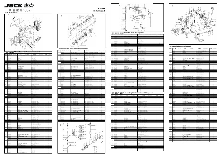
5零件手册Parts ManualA4 系列 A4 Series14. 压料、自动抬压脚分组件/Presser Presser Bar Bar ,Auto Auto Lifter Lifter Components公司件号 Part NO.名称 PartName零件描述 Description压脚扳手螺钉SM9/64"x40 L=11Screw SM9/64"x40 L=11压脚扳手螺钉垫圈Washer 压脚扳手Hand lifter O 型圈Rubber ring 压脚扳手凸轮分部件Hand lifter cam asm.前杠杆螺纹销Screw 螺纹销橡胶垫圈(厚)Washer (H )抬压脚前杠杆分部件Lift front lever component 抬压脚拉杆Knee lifter pull rod 5. 送料分组件/Feed Feed Mechanism Mechanism ComponentsGB/T896-1986挡圈 5Snap ring Main Shaft & Thread Take-up Components压脚升降板Lifting plate序号NO.公司件号 Part NO.名称 PartName零件描述 Description数量 Number抬压脚拉杆螺钉SM3/16"x32Hinge Screw SM3/16"x32Part NO.名称 PartName零件描述 Description后杠杆轴位螺钉SM15/64"x28Hinge screw SM15/64"x28111405015倒送料连杆Reverse feed connecting rod 11. 机壳、外装分组件/Machine Frame & Miscellaneous Cover Components抬压脚后杠杆Knee lifter back lever 11305015倒送料连杆(-7)Reverse feed connecting rod(-7)1挑线连杆销 (厚料)Thread take-up connecting rod pin (抬压脚顶杆Knee lifter connecting rod 211426021倒送料连杆销Connecting rod pin 1公司件号 Part NO.名称 PartName零件描述 Description挑线连杆销Thread take-up connecting rod pin 松线导管上支架Wire release bracket upper 11326011倒送料连杆销(-7)Connecting rod pin(-7)1上轮螺钉 SM15/64"x28 L=15Screw SM15/64"x28 L=15松线导管压板Wire release press plate 3101S11005螺钉 SM9/64"x40 L=6Screw SM9/64"x40 L=66101S11001后窗板螺钉SM3/16"×28 L=9Screw SM3/16"×28 L=9挑线连杆(厚料)Thread take-up connecting rod (H)油管压板螺钉SM3/16"x28 L=7Screw SM3/16"x28 L=7410101053送料调节器Feed regulator 110122003面板调节孔螺塞Rubber plug 挑线连杆Thread take-up connecting rod 松线导管压板螺钉M4x8Screw M4x8511403043送料调节器轴套Feed regulator bushing 113837002商标牌Head card GB/T896-1986挡圈Snap ring 抬压脚前杠杆组件Knee lifter lever asm 6101S11023送料调节器轴端螺钉SM3/16"x28 L=6.5Screw SM3/16"x28 L=6.51302591面板(喷漆)Face plate asm 垫片washer713826005标盘螺柱Feed regulator stud 113813005左线钩Thread guide left 针杆曲柄护板Needle bar crank protecting plate 810122016送料调节螺钉O形圈Rubber ring 1101S11007右线钩螺钉SM11/64"×40 L=6Screw SM11/64"×40 L=6挑线杆分组件Thread take-up lever asm.913811008固定表盘Fixing dial plate 113822006面板垫Face plate gasket 挑线杆组件(厚料)Thread take-up lever asm.(H )13811008固定表盘(-7)Fixing dial plate(-7)1101S11027防油板螺钉SM1/8"×44 L=3.4Screw SM1/8"×44 L=3.4挑线杆滚针轴承Needle bearing 13811013固定表盘(H-M )Fixing dial plate(H-M)110412007面部防油板Face oil shield asm.挑线曲柄分部件Thread take-up crank 10H05018GB/T896-1986挡圈3.5Snap ring 3.5111412082面部防油板(厚料)Face oil shield asm.(H)挑线曲柄分部件(厚料)Thread take-up crank (H )1113811009标盘按钮Dial plate button 110122013针杆上衬套孔塞Rubber plug 挑线曲柄分部件(H-M )Thread take-up crank (H-M )1213827002按钮复位簧Spring110122005挑线连杆销螺孔塞Rubber plug 针杆连杆Needle bar connecting rod 1313812010上限位片Upper limit patch 110122004针杆曲柄螺孔塞Rubber plug挑线曲柄螺钉(左旋)Screw141381100700标盘旋钮组件Knob component 1101S11004挑线杆护罩螺钉SM3/16"×28 L=7Screw SM3/16"×28 L=7针杆曲柄紧固螺钉 SM9/32"x28 L=16Screw SM9/32"x28 L=1615101S11022送料距旋钮螺钉SM3/16"x28 L=18Screw SM3/16"x28 L=181********挑线杆防护罩Thread take-up lever cover 针杆曲柄定位螺钉SM9/32"x28 L=16Screw SM9/32"x28 L=16101S11004挑线杆护罩螺钉SM3/16"×28 L=7Screw SM3/16"×28 L=7针杆曲柄Needle bar crank 13512004三孔线勾3-hole thread guide 针杆曲柄(厚料)Needle bar crank (H )10122005挑线连杆销螺孔塞Rubber plug送料轴挡圈螺钉SM1/4"x40 L=6Screw SM1/4"x40 L=6114S11015割线刀螺钉SM9/64"×40 L=6Screw SM9/64"×40 L=6上轴前轴套组件Main shaft bushing front 11419001割线刀Knife 夹线器螺钉SM15/64"x28 L=7Screw SM15/64"x28 L=720722002油塞Rubber plug 主轴中轴套Main shaft bushing mid 13822001操作屏孔塞Rubber plug 上轴中套挡圈螺钉Screw13822007后窗板垫Side plate gasket 上轴挡圈Main shaft thrust collar 302592后窗板(喷漆)Side plate挡圈20Snap ring 20101S11001后窗板螺钉SM3/16"×28 L=9Screw SM3/16"×28 L=9送料偏心轮 Feed eccentric cam 13811031一体机电控罩壳(鲍麦克斯)Electronic control box 送料偏心轮(厚料)Feed eccentric cam (H)W01009GB/T97.1-1985垫圈 5Washer 5送料偏心轮(H-M)Feed eccentric cam (H-M)114S13001直驱电机螺钉M5×20Screw M5×20送料偏心轮盖板Cover plate 114S30001螺栓(内六角)M5×25Screw M5×25送料偏心轮盖板(H-M)Cover plate(H-M)13833010一体机电控组件(琦星)Electronic control box(Q)送料偏心轮螺钉 SM1/4"x40 L=13Screw SM1/4"x40 L=1313833013一体机电控组件(鲍麦克斯)Electronic control box 护针片螺钉 SM9/64"x40 L=5Screw SM9/64"x40 L=510122006送料调节器孔塞Rubber plug 上轴后轴套The rear axle sleeve 10122007下轴工艺孔塞Rubber plug 上轴后套挡油油封Oil seal 138S05001操作面板螺钉ScrewGB/T894.1-1986挡圈15Snap ring 1513833012一体机电控面板组件(琦星)Control panel(Q)上轴Main shaft 13833015一体机电控面板组件(鲍麦克斯)Control panel 手轮贴条Handwheel lable 101S12001底板支柱Machine head stud 螺钉Screw 13822002装饰条Decorative article 手轮(喷漆)Handwheel 101S11004螺钉Screw电机罩壳组件(配琦星)Motor cover asm(Q)1381300400小夹线器组件Thread tension asm.电机罩壳组件(配鲍麦克斯)Motor cover asm138S16019小夹线器螺母Thread tension nut 电机光栅组件(配鲍麦)Motor grating sensor asm 11227001小夹线弹簧Thread tension spring6`12. 机头附件(1)-线架组件/Machine Head Accessories(1)-Thread Stand Components公司件号 Part NO.名称 PartName零件描述 Description8. 润滑、油量检测组件/Oil Oil Lublication 、Oil Oil Measuring Measuring Components20131019线架杆顶防护橡皮Spool rest rod rubber cap 公司件号 Part NO.名称 PartName零件描述 Description数量 S04050 十字槽凹穴六角头螺栓 M5 L=16 Screw M5 L=16 W01047垫圈M5Washer M5油窗Oil sight window N01034 螺母 M5Nut M510122019油窗O形圈Rubber ring 13831022上线架过线杆 Spool rest arm upper 上轴供油管Main shaft oil tube 10113011过线圈(内)Thread guide ring 112S30005油泵连接螺柱Oil pump connecting stud 10113010过线圈(外) Thread guide ring 11329010开口挡圈10Snap ring 1013831019线架杆上节Spool rest rod upper 6. 切线装置部件/Thread Trimmer Components供油管Hook oil tube13831021线架杆接头 Spool rest rod joint 10112020油泵安装板Oil pump installing base 13831020线架杆下节Spool rest rod lower 序号NO.公司件号 Part NO.名称 PartName零件描述 Description数量 NumberW03002弹垫Spring washer10122106橡胶垫圈Spool rest rod rubber ring 209S12001压脚螺钉SM11/64"×40 L=10.5Screw SM11/64"×40 L=10.5W01048垫圈M16Washer M161113S15002定刀调节螺钉SM1/8"x44 L=9.5Screw SM1/8"x44 L=9.5110103022油泵体衬套Oil pump bushing N02008六角薄螺母 M16Spool rest rod nut M16211319001定刀Secant knife 1101S30007柱塞螺钉Plunger Screw 10. 绕线器组件/ Bobbin ComponentsS04051十字槽凹穴六角头螺栓 M5Spool rest arm lower screw M53113S17001螺钉SM9/64"x40Screw SM9/64"x40110127013柱塞簧Plunger spring N01034 螺母 M5Nut M5411312003护针片Needle guard patch 110122018回油柱塞Plunger 公司件号 Part NO.名称 PartName零件描述 Description数量 W03002弹簧垫圈 5Spring washer 55201S11009螺钉SM9/64"x40 L=5.5Screw SM9/64"x40 L=5.5110120001油泵体Oil pump 6113S11001螺钉SM11/64"x40 L=12Screw SM11/64"x40 L=122油泵螺钉Screw1383103900绕线器组件Bobbin winder asm.油泵叶轮Oil pump impeller 114S11008螺钉M4x6Screw M4x6油泵叶轮托板Oil pump impeller cover GB/T97.1 垫圈4Washer油泵盖Lubricating oil pump cover 10113030压线控制板Thread press control plate 101S30006螺钉Screw10111120绕线衬垫Winding pad 1012000100油泵分部件Lubricating oil pump component 13831101绕线器装置主座Bobbin winder bed116S30003抬牙叉固定螺钉SM15/64"×28 L=14.5Screw SM15/64"×28 L=14.5GB/T 896-1986 开口挡圈5Snap ring 10136001供油管接头Rubber joint 10127061复位板拉簧Spring13812110调节板Regulating plate 10110030绕线凸轮Bobbin winder cam S09045螺钉Screw1380510600绕线器连杆组件Bobbin winder connecting rod 13827103满线复位簧spring 10127060弹簧Spring GB/T 896-1986开口挡圈4Snap ring13802111绕线器主轴Bobbin winder mian shaft 13802026绕线凸轮轴Bobbin winder cam shaft S09103绕线轮螺钉Screw13831102绕线轮Bobbin winder wheel O01110O 型圈Ring 11422062密封垫Washer114S11003螺钉SM3/16"×28 L=10Screw SM3/16"×28 L=101381300600底线夹线器Bobbin thread tension asm.13811004夹线螺母Thread tension nut 11427006小夹线弹簧Spring10112005夹线板Thread tension disk 11413022夹线过线板Thread tension guide plate 112S13004夹线螺钉Screw114S16001螺母SM11/64"×40Nut SM11/64"×4012. 机头附件(2)/Machine Head Accessories(2)公司件号 Part NO.名称 PartName零件描述 Description数量 1011203100机头连接钩部件 Hinge component10122060机头连接钩座 Head connecting rubber cushion 10117021机针(14#)Needle (14#)10117022机针DP×5#21(厚料)Needle (H)101S30010 机头连接钩座钉 Nail 10118003梭心 Bobbin机头支柱 Machine head rest pin 20731047螺丝刀(大)Screw driver10131003螺丝刀(中) Screw driver,medium9. 自动倒送料开关、感应抬压脚组件/Automatic Automatic Reverse Reverse Feed Feed ComponentsNO.公司件号 Part NO.名称 PartName零件描述 Description数量 NumberS05254GB/T70.1-2000螺钉M2.5×4Screw M2.5×411383004600下感应探头Lower sensor1201S11012螺钉SM9/64"×40 L=7.7Screw SM9/64"×40 L=7.7113813022过线压板Screw M4x8113822030橡皮塞(单孔)Rubber plug1101S11004挑线杆护罩螺钉SM3/16"×28 L=7Screw SM3/16"×28 L=711403003600双开关组件Auto reverse feed switch asm 1116S30003抬牙叉固定螺钉SM15/64"×28 L=14.5Screw SM15/64"×28 L=14.52W02004GB/T93-1987弹垫M6Spring washer M621011628005抬牙叉固定螺钉垫圈Washer2杰克缝纫机股份有限公司杰克缝纫机全球销量遥遥领先1383003400自动倒送料电磁铁Auto reverse feed solenoid 111. 油盘、膝抬压脚分组件/Oil Ceservoir,Knee Lifter Components1383003500自动倒送料电磁铁(-7)Auto reverse feed solenoid(-7)11211326005销子Pin 1序号NO.公司件号 Part NO.名称 PartName零件描述 Description数量 Number110122022油盘座垫Oil reservoir rubber cushion 1213801020油盘Oil Reservoir 1公司地址(Address of Company):310111005抬压脚顶杆Knee lifter push rod 1台州市椒江区机场南路15号410122020油盘垫Oil Reservoir gasket 1No.15 Rd Airport South,Jiaojiang District Taizhou City,Zhejiang,P.R.C 7. 自动抬压脚组件/Auto Lifter Components510122021O 型圈Rubber ring1邮编( Zip Code ):3180006101S11028排油孔螺钉SM5/16"×24 L=7Screw SM5/16"×24 L=72国内销售部(Domestic Trade Department):Part NO.名称 PartName零件描述 710131001油盘磁铁Oil reservoir magnet 1电话(TEL):0086-0576-******** 88177789810122023油盘支架Oil reservoir rubber cushion 1传真(FAX):0086-0576-********销子Pin 910112027抬压脚双向曲柄Knee lifter crank 1国贸部(International Trade Department):开口销 GB/T91 2×14Cotter pin电话(TEL):0086-0576-******** 88177774电磁铁接头Solenoid connector 传真(FAX):0086-0576-********法兰螺母M8Flange nuts M8服务热线:400-8876858电磁铁组件Solenoid asm.2018.12后窗板螺钉SM3/16"×28 L=9screw SM3/16"×28 L=9资料如有更改,恕不另行通知,以实物为准。
潘美亚双电机齿轮箱套件说明书

Tamiya 70097 Twin-Motor Gearbox KitTank-style chassis built using the Tamiya 70100track and wheel set, Tamiya 70098 universal plateset, and Tamiya 70097 twin-motor gearbox kit.OverviewThe Tamiya twin-motor gearbox is a small (3-inch long) plastic gearbox. It contains two small brushed DC motors that drive separate 3mm hexagonal output shafts. There are two ways to put the kit together: with a high-speed 58:1 gear ratio or with a slower 203:1 gear ratio. Either way, the motors provide plenty of power to drive any small robot. For a gearbox with a similar form factor and more gear ratio options, see the Tamiya double gearbox.Complementary productsThe output shafts included in this kit are 3 mm hexagonal axles that are 10 cm (about four inches) from tip to tip. The axles work with any of the Tamiya wheels we carry, giving you many options for your robot speed. The two low-voltage motors run on 3-6 volts and draw up to a few amps, making them perfect candidates for the Pololu low-voltage dual serial motor controller and the DRV8833 motor driver carrier. Motor overheating can be caused by excessive stalling, even at very low voltages. We recommend that you use stall-detection sensors, or just watch your robot, to make sure that it doesn’t stall for more than a few seconds at a time. For motor specs, see the Mabuchi motor FA-130 (#18100) data sheet (58k pdf).Note that you can replace the motor in this kit with a lower-current, higher-voltage motor if you want to use this gearbox with controllers such as the qik 2s9v1 dual serial motor controller, TB6612FNG dual motor driver carrier, or Baby Orangutan B-328 robot controller.Comparison to the Tamiya double gearboxThe twin-motor gearbox is very similar to the Tamiya 70168 double gearbox, as shown in the picture to the right. The gear ratio options of the two products complement each other well, but the mounting holes and overall dimensions vary slightly. The double gearbox is shorter and wider thanthe twin-motor gearbox, and the gears are a bit smaller and wider. This should make the double gearbox a bit more robust, though we have not heard any reports of the twin-motor gearbox gears breaking.To compare all Tamiya gear box kits, see the Tamiya Gearbox Gear Ratio Comparison.Note: The twin-motor gearbox is a kit; assembly is required. To use the kit in roboticsprojects, you need to connect the motors to your own robot controller.Documentation on producer website.。
日立钻机报警信息

日立钻孔机报警信息--------+------------------------------------------------------------------------+-------|系统参数错误|EMG--------+------------------------------------------------------------------------+-------1. 系统参数档 "NBACKUP" 已破坏.2. 系统参数档未正确格式化.当出现此错误讯息时,请使用系统备份档.--------+------------------------------------------------------------------------+-------|水平均等(TH) 错误|RESET--------+------------------------------------------------------------------------+-------读取程式带或是由通信回线下载至程式部时,文字单位下的parity(水平parity)发生错误.通常,1文字单位中的论理 "1" 位数,"EIA"指令是偶数,"ASCII"指令是奇数.--------+------------------------------------------------------------------------+-------|垂直均等(TV) 错误|RESET--------+------------------------------------------------------------------------+-------读取程式带或由通信回信下载至程式部时,TV(垂直parity)检查机能在有效状态下,语数parity发生错误.为使用此机能(TV检查机能),1区块中的语数就必须是 "偶数" .若1区块中的语数是 "奇" 的话,便会发生错误.--------+------------------------------------------------------------------------+-------|数字位数超出|RESET--------+------------------------------------------------------------------------+-------1字词(语句)中,数字资料的位数过多.请确认程式中的数字位数并修正之.--------+------------------------------------------------------------------------+-------|位址错误|RESET--------+------------------------------------------------------------------------+-------1字词(语句)或指令(命令)的格式不正确.程式中无指令,而数值资料却被输入.请修正程式.--------+------------------------------------------------------------------------+-------|数字错误|RESET--------+------------------------------------------------------------------------+-------1字词(语句)中仅有位址指令.意即,位址指令接连著却无数值资料.请修正程式.--------+------------------------------------------------------------------------+-------|不当"-" 指令|RESET--------+------------------------------------------------------------------------+-------在无法使用负号符号符 "-" 的字词(语句)下,使用了负向符号 "-" .请除负号符号.--------+------------------------------------------------------------------------+-------|不当"." 指令|RESET--------+------------------------------------------------------------------------+-------在无法使用小数点 "." 的字词(语句)下,使用了小数点 "." .请除小数点.--------+------------------------------------------------------------------------+-------|未定义位址|RESET--------+------------------------------------------------------------------------+-------1字词(语句)中,使用了未定义的字词位址.请确认在程式部中是否含有无法使用之指令,有无修正程式之必要,或变更参数263的位数,即由3改为0并忽视未定义位址.--------+------------------------------------------------------------------------+-------|未定义"G#" 指令|RESET--------+------------------------------------------------------------------------+-------使用了未定义的G号码命令.确认程式部是否含有无法使的G指令,有无修正程式的必要,或将参数263的位数由1变更为0并忽视未定义的G指令.--------+------------------------------------------------------------------------+-------|未定义"M#" 指令|RESET--------+------------------------------------------------------------------------+-------使用了未定义的M号码命令.确认程式部是否含有无法使用的M指令,有无修正程式的必要,或是将参数263的位数由2变更为0并忽视未定义M指令.--------+------------------------------------------------------------------------+-------|终了指令错误|RESET--------+------------------------------------------------------------------------+-------程式部未因终了指令(程式结束命令)而关闭.确认程式终了时有无终了指令(M02,M30,M99),并修正程式.--------+------------------------------------------------------------------------+-------|不当读出辅助程式指令|RESET--------+------------------------------------------------------------------------+-------副程式的呼出指令格式不正确.呼出副程式时,发现档名或基准标值未被输入.--------+------------------------------------------------------------------------+-------|不当重覆指令|RESET--------+------------------------------------------------------------------------+-------未正确使用重覆指令(重覆命令).在记忆型的的重覆指令(P)下,发现无座标值或其它指令.请修正程式.--------+------------------------------------------------------------------------+-------|辅助程式未登录|RESET--------+------------------------------------------------------------------------+-------从主程式呼叫副程式时,却找不到副程式.先确认由主程式所呼叫的副程式号码,或是对应此程式的档名後,再修正程式.--------+------------------------------------------------------------------------+-------|多重辅助程式读出超出|RESET--------+------------------------------------------------------------------------+-------多重副程式超出限度.修正程式,并将副程式的多重呼出减至8重 (圈) .--------+------------------------------------------------------------------------+-------|不当重覆位址|RESET--------+------------------------------------------------------------------------+-------在此区块中,相同的位址文字有2个或以上被使用.将重覆而无法使用的指令分割至其它区块或将它除.|诊断号码未寻获|RESET(枹巊梡)--------+------------------------------------------------------------------------+-------在程式部中找不到所指定的SEQUENCE号码 (No.) .请输入正确的SEQUENCE号码.--------+------------------------------------------------------------------------+-------|不当S&R 读出指令|RESET--------+------------------------------------------------------------------------+-------STEP&REPEAT(S&R)命令是在无S&R 开始命令的状态下,所受到的指令.请修正程式部.欲登录PATTERN的区块前端中,可追加开始指令(S;),或在不使用STEP&REPEAT的情况,除S&R (M08;)登录终了指令.|未实施原点复归|RESET--------+------------------------------------------------------------------------+-------实施原点复归前,先确认,是否已按下CYCLE SATRT钮,或已从键盘输入开始命令.为清除讯息,首先按下操作面板上的RESET钮,接下来为进行原点复归,请按下操作面板中的 HOME按钮.当实行原点复归後,机械即可操作.--------+------------------------------------------------------------------------+-------|不当终了辅助程式指令|RESET--------+------------------------------------------------------------------------+-------主程式的程式部,含有副程式的终了指令.确认副程式是否被当为主程式使用,若为主程式之程式部的话,请修正之.--------+------------------------------------------------------------------------+-------|不当S&R 开始指令|RESET--------+------------------------------------------------------------------------+-------副程式中含有STEP&REPEAT (S&R) 的开始指令.请除副程式中的S&R 开始指令(S;).--------+------------------------------------------------------------------------+-------|不当S&R 终了指令|RESET--------+------------------------------------------------------------------------+-------副程式中含有STEP&REPEAT (S&R) 的终了指令.请除副程式中的S&R 登录终了指令(M08;).--------+------------------------------------------------------------------------+-------|磁片格式不当|RESET--------+------------------------------------------------------------------------+-------1. T#C#命令(T号码C号码)下所指定的钻针直径,已在规定范围外.2. 字词(语句) 的组合未定义 (规定外) .--------+------------------------------------------------------------------------+-------|磁片容量已满|RESET--------+------------------------------------------------------------------------+-------因为在 TAPE模式, FD模式或 REMOTE模式下,若实行长的程式部,而此程式部的大小又比系统磁片中的程式缓冲器大的话,就会出现讯息.当发生此情时,请使用NC BUFF LOCK 机能.关于NC BUFF LOCK 机能,请参照操作手册.--------+------------------------------------------------------------------------+-------|磁片未就绪|RESET--------+------------------------------------------------------------------------+-------此讯息出现是因为程式部的档名在 FD模式下所指定之处,发现磁片(软碟片)未插入,#1 槽内.将程式部磁片插入#1 槽後,请作正确的操作.--------+------------------------------------------------------------------------+-------|速度指令指定范围外|RESET--------+------------------------------------------------------------------------+---------------+------------------------------------------------------------------------+-------|回转指定范围外|RESET--------+------------------------------------------------------------------------+-------T#S#命令(T号码S号码)下所指定的SPINDLE(RPM)在规定范围外.--------+------------------------------------------------------------------------+-------|工具径设定范围外|RESET(枹巊梡)--------+------------------------------------------------------------------------+-------T#C#命令(T号码C号码)下所指定的钻针直径在规定范围外.--------+------------------------------------------------------------------------+-------| 错误|RESET--------+------------------------------------------------------------------------+-------X,Y轴的任一轴都不在5mm网眼上.使网眼检查无效(参数500的第0位数为0),或请修正程式.--------+------------------------------------------------------------------------+-------|指定档读入错误|RESET--------+------------------------------------------------------------------------+-------禁止读取所指定的档案.--------+------------------------------------------------------------------------+-------|指定档防写|RESET--------+------------------------------------------------------------------------+-------禁止写入所指定的档案.--------+------------------------------------------------------------------------+-------|档案未登录|RESET--------+------------------------------------------------------------------------+-------当出现此讯息表示在FD模式下所指定的程式部档名并不存在于程式部的磁碟上.请检查档名及程式部磁碟.--------+------------------------------------------------------------------------+-------|档名不正确|RESET--------+------------------------------------------------------------------------+-------所指定的档名有错误.--------+------------------------------------------------------------------------+-------|辅助程式超出|RESET--------+------------------------------------------------------------------------+-------G26 和 G25 间的副程式个数超出64个.请将副程式的个数设于 64个以下.--------+------------------------------------------------------------------------+-------|多重S&R 超出|RESET--------+------------------------------------------------------------------------+-------在STEP&REPEAT(S&R)中,发现S&R 指令重复.请将程式部修正为仅有1组S&R 的指令.--------+------------------------------------------------------------------------+-------|不当"+" 指令|RESET--------+------------------------------------------------------------------------+-------在不可使用"+" 符号的位址下,使用了 "+" 符号.请将正号符号除.--------+------------------------------------------------------------------------+-------|数值指定范围外|RESET--------+------------------------------------------------------------------------+-------使用了过大或过小的数值.请修正为指定内的数值.--------+------------------------------------------------------------------------+-------|参数资料错误|RESET(枹巊梡)--------+------------------------------------------------------------------------+-------参数设定错误.--------+------------------------------------------------------------------------+-------|指令组合错误|RESET--------+------------------------------------------------------------------------+-------程式部中的指令未正确配置.请确认程式并修正之.请确认诊断画面的资料,并向日立VIA连络.--------+------------------------------------------------------------------------+-------|格式化错误|RESET--------+------------------------------------------------------------------------+-------1. 软碟片未格式化.2. 软碟片的recording格式化错误.3. 软碟片可能已遭破坏.请进行CHKDSK (检查软碟片),并尝试修复软碟.若无法修复的话,请中止使用此软碟片.若无特别指定,在 CNC 下所使用的软碟片,适用下列仕样.1. 3.5" (Inch),两面,密度,SOFTsector2. recording格式化:HITACHI 格式,IBM格式或是MS-DOS格式--------+------------------------------------------------------------------------+-------|I/O 装置使用中|RESET--------+------------------------------------------------------------------------+-------所指定的装置,现在使用中.(Tape-reader,Disk-driver,或是通信线)使用自动运转装置时,必须中止加工作业.当装置的运作终了时,即可使用之.--------+------------------------------------------------------------------------+-------|讯息档读入错误|EMG--------+------------------------------------------------------------------------+-------1. 系统讯息档 "NMSGFOR" 或是 "NMSGJPN" 已遭破坏.2. 系统参数档未正确格式化.当出现此错误时,请使用备份的系统软体片载入之.--------+------------------------------------------------------------------------+-------|机械MACRO 读入错误|EMG--------+------------------------------------------------------------------------+-------Sub No.6 : machine macro read error7 : translator1 read error8 : tape macro read error9 : machine macro EXIT errorA : translator1 EXIT errorB : tape macro EXIT errorC : message ID check-sum errorD : parameter structure body check-sum errorE : ET1 read errorF : ET2 read error10 : ET3 read error11 : ET4 read error12 : ET1 EXIT error13 : ET2 EXIT error14 : ET3 EXIT error15 : ET4 EXIT error1. The program file is destroyed.2. The format of system parameter file is not correct.3. Check the contents of DIAG. 21 and 25.If such an error has appeared, use (load) another system software disk (for backup).--------+------------------------------------------------------------------------+-------|不当辅助程式开始指令|RESET--------+------------------------------------------------------------------------+-------主程式以外的情形是副程式中已含开始(登录)指令.请在主程式下使用副程式登录开始指令(G26).--------+------------------------------------------------------------------------+---------------+------------------------------------------------------------------------+---------------+------------------------------------------------------------------------+-------|MACRO 演算错误|RESET--------+------------------------------------------------------------------------+---------------+------------------------------------------------------------------------+-------|MACRO 变数指定错误|RESET--------+------------------------------------------------------------------------+---------------+------------------------------------------------------------------------+---------------+------------------------------------------------------------------------+---------------+------------------------------------------------------------------------+-------|MACRO 容许范围外|RESET--------+------------------------------------------------------------------------+---------------+------------------------------------------------------------------------+-------|圆弧容许误差范围外|RESET--------+------------------------------------------------------------------------+-------圆弧补间的起点到中心距离及终点到中心距离的差,超出容许值.请修正圆弧的半径,起点或是终点.容许误差的设定是在参数261.--------+------------------------------------------------------------------------+-------|圆弧切削速度超出|RESET--------+------------------------------------------------------------------------+---------------+------------------------------------------------------------------------+-------|同时轴数指令超出|RESET--------+------------------------------------------------------------------------+---------------+------------------------------------------------------------------------+-------|平面选择指令异状|RESET--------+------------------------------------------------------------------------+-------|修饰面指令异状|RESET--------+------------------------------------------------------------------------+---------------+------------------------------------------------------------------------+-------|修饰面次指令异状|RESET--------+------------------------------------------------------------------------+---------------+------------------------------------------------------------------------+-------|工具径补正开始,取消不正确|RESET请在圆弧补间(G02,G03)下进行钻径补正的START-UP(G41,G42)及取消(G40).请直线补间(G01)下进行钻径补正的START-UP及取消.--------+------------------------------------------------------------------------+-------|工具径补正切进量过多|RESET--------+------------------------------------------------------------------------+-------若做比钻径off set还小的段差加工作业的话,将会发生此情形.请修正程式.详细请参照比手动程式之钻径补正的钻针半径还小的段差加工作业.--------+------------------------------------------------------------------------+-------|工具径补正干涉检查错误|RESET作锐角之角的加工时,依钻径off set若发生钻针切进到素材内时,将出现此错误讯息.请修正程式.详细请参照手动程式之钻径补正的切断干涉检查.--------+------------------------------------------------------------------------+-------|工具径补正无交点|RESET--------+------------------------------------------------------------------------+-------根据角的形状而无法计算钻径off set的经路时,将出现此错误讯息.请修正程式.详细请参照手动程式之钻径补正.--------+------------------------------------------------------------------------+-------|作业完了|START-Y若在程式中检测出 "作业终了"指令 (日立格式为: M04 )时,将会出现此讯息.若欲重新加工时,请按下操作面板上的CYCLE START钮.--------+------------------------------------------------------------------------+-------|程式停止|START-Y--------+------------------------------------------------------------------------+-------程式部实行中,若有下列情况时,将会出现此讯息.1. 程式头的最後端来到时2. 程式部中,发生程式停止命令时3. 根据 "TIL" 命令,钻针完成加工时重开程式部时,请按操作面板上的CYCLE START钮.|选择性项目停止|START-Y--------+------------------------------------------------------------------------+-------选购停止机能为"有效"的情况下,会依据程式部的选购停止命令而出现此讯息.重开程式部时,请按操作面板上的CYCLE START钮.--------+------------------------------------------------------------------------+-------|程式表头|START-Y--------+------------------------------------------------------------------------+-------程式中,若检测出"tape前头 "指令 (日立格式为: % )时,便会出现此讯息.重新加工时,请按操作面板上的CYCLE START钮.--------+------------------------------------------------------------------------+-------|程式重头|START-Y--------+------------------------------------------------------------------------+-------此讯息是表示SKIP命令已终了.硬体程式再开时,请按操作面盘上的CYCLE START钮.--------+------------------------------------------------------------------------+-------|表头指令不正确|RESET--------+------------------------------------------------------------------------+-------前头部,含有不适当资料.程式头指令(日立格式=G48 Excellon格式=M48)起到%间使用了不可使用之命令.请确认程式并进行修正.--------+------------------------------------------------------------------------+-------|NTRANS1 读入错误|EMG--------+------------------------------------------------------------------------+-------读取程式解析前处理部时,发生错误.「NTRANS1」档是否不存在,即使存在著,其内若已遭到损坏,当系统载入时,便会出现此讯息.不管是哪一种情况都必须从备份的磁碟片重灌,为使原因明确请如下述操作之.背景而言,DIR 0 FOR NTRANS1*[cr]请如上输入.若档案无任何表示的话,可能是有某种原因使得「NTRANS1」档消失了.若出现档名,表示其内已遭到破坏.并请告知所表示的内容(位组数,日期等).处置而言,请以备份的FDNo.5-2再重灌之.--------+------------------------------------------------------------------------+-------|NTPMAC 读入错误|EMG--------+------------------------------------------------------------------------+-------TAPE MACRO处理部(一个G指令让它变为复数动作的处理)发生读取错误.「NTPMAC」档是否未存在,即使存在其内也遭到破坏的情况,当系统载入时便会出现此错误讯息.不管是哪一种情况都必须从备份的磁碟片重灌,为使原因明确请如下述操作之.背景而言,DIR 0 FOR NTPMAC*[cr]请如上输入.若档案无任何表示的话,可能是有某种原因使得「NTPMAC」档消失了.若出现档名,表示其内已遭到破坏.并请告知所表示的内容(位组数,日期等).处置而言,请以备份的FDNo.5-2再重灌之--------+------------------------------------------------------------------------+-------|未定义装置指定|RESET--------+------------------------------------------------------------------------+-------所指定的装置未被定义.关于Device号码,请参下表,检查之.Device号码 (Device No.)0: Hard Disk Drive 01: Hard Disk Drive 12: FD Drive 23: Hard Disk Drive 3TR: Tape LeaderRI: RS232C输入埠RO: RS232C输出埠FR: DNC--------+------------------------------------------------------------------------+-------|等待开始|START-Y--------+------------------------------------------------------------------------+-------此讯息出现于下列情形.若机械呈现禁止作动状态的话(Interlock中),而欲使机械动作的话,当给予某一命令的话(例如,交换钻针,或JOG命令),即会出现此讯息.首先,以适当操作解除Interlock状态,接著为活用前述命令,请按操作面板上的CYCLE START钮.--------+------------------------------------------------------------------------+-------|内部演算部错误|EMG--------+------------------------------------------------------------------------+-------首先,关闭NC 电源後再重新启动电源.当此讯息无法消除时,请连络日立VIA.--------+------------------------------------------------------------------------+-------|选择性项目名未寻获|START-Y--------+------------------------------------------------------------------------+---------------+------------------------------------------------------------------------+-------|工具径未设定|RESET--------+------------------------------------------------------------------------+---------------+------------------------------------------------------------------------+-------|不当使用POST DRILL |START-R--------+------------------------------------------------------------------------+-------寿命设定值检查机能下,寿命设定值为0或欲在指定孔数以上的POST作钻孔时,便会出现此讯息.仅在作寿命设定值为0的POST之检查时,将指定孔数的设定值设为99999999.寿命设定值检查机能有效/无效切换参数位数6 0: 无效 1: 有效指定孔数参数 - S3--------+------------------------------------------------------------------------+-------|硬碟错误|EMG--------+------------------------------------------------------------------------+-------在Disk中,发生物理上的陷.当出现此讯息时,表示无法在使用此Disk了.请使用系统软体Disk的copy版(disk)或其它的程式部Disk.--------+------------------------------------------------------------------------+-------|伺服器未就绪|EMG--------+------------------------------------------------------------------------+-------伺服DRIVER AMP处于无法使用状态.当确认好伺服AMP的警报表示後,请连络日立VIA的维修人员.--------+------------------------------------------------------------------------+-------|参数设定错误|EMG--------+------------------------------------------------------------------------+-------伺服参数错误.当出现此讯息时,请使用备份的系统软体片载入之.Sub-Code Contents*602 wrong stored stroke range (+)*605 wrong processing speed establishment value*606 wrong JOG feed speed establishment value0410 time fixed number establishment error (Servo-main : CH) *612 wrong stored stroke range (-)*621 servo compensation parameter establishment error^* : A axis number.0: servo main1-F: servo sub--------+------------------------------------------------------------------------+-------|SEQUENCER 诊断光纤关系错误|EMG--------+------------------------------------------------------------------------+-------A communication error has occurred in signal transfer between MCU board and COMPACK/IOU board through the optical fiber cable.If this message has appeared, check the following items.1. Whether the machine is turned on.2. Cable connection.3. MCU board or COMPACK/IOU board may be troubled.Start sequencer diagnosis application and check "R546".Turn off and on power, and check whether the system restarts properly. b7 b6 b5 b4 b3 b2 b1 b0+----+----+----+----+----+----+----+----+R546 | MMC ALARM LIST | MMC No. |+----+----+----+----+----+----+----+----+b0-b3 : error occurrence MMC number (1 - 5)b4 : phase detection error (PDE)b5 : NO ACK error (NAE)b6 : continuous parity error (PCE)b7 : emergency stop (a fatal error) (EMG)--------+------------------------------------------------------------------------+-------|SEQUENCER 诊断硬体错误 [] |EMG--------+------------------------------------------------------------------------+-------Hard error or system error has occurred in the sequencer section. For details, refer to diagnosis No. 14.Diagnosis :08H = illegal timer interrupts09H = LADDER I/O establishment error10H = LADDER OBJECT wrong14H = MMC fatal error15H = LADDER ENGINE NOT READY17H = bus time out error20H = undefinition interrupts30H = Sequencer NOT RUNHard error or system error has occurred in the sequencer section. For details, refer to diagnosis No. 14.If this message has appeared, check the following items.1. Whether the machine is turned on.2. If diagnosis No. 14 s 14H, the cable connection may be faulty.3. If diagnosis No. 14 is 09H or 10H, use (load) another system software disk (for backup).4. MCU board or COMPACK/IOU board may be troubled.Turn off and on power, and check whether the system restarts properly. --------+------------------------------------------------------------------------+-------|RS-232C 转送错误|RESET--------+------------------------------------------------------------------------+-------During DNC1 communication, a parity error, a flaming error or a over runerror occurred.Check the next item when this message is indicated.1. Check the setting of DNC communication for NC with DNC utility program and check the setting is proper or not for HOST controller.2. Check the setting of DNC communication for HOST controller and checkthe setting is proper or not.3. Check interface cable and connector.4. Check interface wiring.5. Interface device.--------+------------------------------------------------------------------------+-------|PC-MCU 轻度通信错误|RESET--------+------------------------------------------------------------------------+-------The communications processing error between PC and MCU board occurred. Sub-Code Contents0001 Communication NOT READY0002 Channel number injustice0003 Undefinition comment0004 Recieve data is nothing0005 Chanel in under using0006 Illegal send sequence0007 Answer request without receive command--------+------------------------------------------------------------------------+-------|伺服 CPU 错误 [,0413] |EMG--------+------------------------------------------------------------------------+-------The obstacle of the servo CPU or the hard difficulty of the CPU circuit board occurred.As for the details of contents of an error, it is indicated in the sub-number.If it occurred in what kind of operation, and it asks for the record of the sub-number.Check the next item when this message is indicated.1 . DC power supply (+5V, MCU32 . MCU circuit board3 . PCNTS circuit board4 . SCOM circuit board5 . SCOM-PCNTS cableTurn off a power supply, and confirm whether a system stands up normallyby the re-injection.Sub-Code Contents*273 For the expansion[TLB protection exception (read)] *274 For the expansion[TLB protection exception (write)] *275 For the expansion[First page write excsption]*276 For the expansion[TLB Miss exception /TLB effect-less exception (write)]*277 For the expansion[TLB Miss exception /TLB effect-less exception (read)]*280 zero profit*281 address error*287 wrong slot rode*291 undefinition interrupts*493 DC power supply abnormal*494 time out error*295 SCOM difficulty (communication time out) .circuit board number of sheets error*296 There are no directions for the connection that a setup ofshaft classification is changed after power on.*498 Watchdog error*2A4 operation code error*2B1 integer operation overflow*0E0 servo-sub EPROM difficulty*0E1 servo-sub SRAM difficulty*0E2 servo-sub FROM difficulty*0E8 servo-sub DPRAM difficulty*0EA servo-sub FROM writing error (at the SYSGEN)*0F0 servo-main SRAM difficulty^* : A axis number.0: servo main1-F: servo subIf this message has appeared, check the following items.1. DC power supply (+5 V series, MCU3 V series).2. MCU board.3. PCNTS board4. SCOM board5. SCOM-PCNTS cableNote the alarm number and sub number when the alarm has occurred. Turn off and on power, and check whether the system restarts properly. --------+------------------------------------------------------------------------+-------|伺服实行错误|POWER--------+------------------------------------------------------------------------+-------The movement difficulty of the servo part occurred.As for the details of contents of an error, it is indicated in the sub-number.If it occurred in what kind of operation, and it asks for the record ofthe sub-number.Check the next item when this message is indicated.1. DC Slowdownpower supply (+5V, MCU32. MCU circuit board3. SCOM circuit board4. PCNTS circuit board5. SCOM-PCNTS cable6. the system version of the servo main / servo subTurn off a power supply, and confirm whether a system stands up normallyby the re-injection.Sub-Code Contents*607 data storage set error*310 servo-sub no answer(initials & parameter transmission)*311 servo-sub no answer(counter reset)*312 servo-sub no answer(For the expansion)*313 servo-sub no answer(servo ON)*314 servo-sub no answer(For the expansion)*315 servo-sub no answer(servo ON confirmation)*316 servo-sub no answer(coordinate)*317 servo-sub no answer(coordinate establishment confirmation)*318 servo-sub no answer(For the expansion)*319 servo-sub no answer(For the expansion)*31A servo-sub no answer(For the expansion)*520 the version inconsistency of the servo system*620 Acceleration/Slowdown calculation error*580 the slowdown process time out that is in a hurry*581 wrong command reception in the parameter reception(201 level)。
台邦无刷直流减速电机
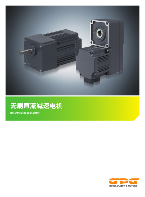
直流电机的一般规格 General speci cations of DC motor
项目 Item
绝缘电阻 Insulation resistance
绝缘电压 Insulation voltage
温度上升 Temperature rise
绝缘等级 Insulation class
使用温度 Using temperature
使用湿度 Using humidity
参数 Parameter
在常温、常湿度下,运转电机后,以 DC500V 电阻表测量线圈、外壳间时,测量值为 20MΩ 以上。 In the circumstance of normal ambient temperature and humidity, the resistance can be up to 20MΩ or more when 500VDC megge is applied between the windings and the frame after rated motor operations.
LORD 轴承抵抗器使用与维护指南说明书
LORD® Axial Isolator Use and Maintenance Manual Patent No.: US 10,480,260 B2LORD Axial Isolator Use and Maintenance Manual Table of ContentsQuick Reference Charts (iv)1.0 Introduction (1)2.0 Function (1)3.0 Assembly into MWD/LWD Tool String (1)3.1 Mechanical (1)3.2 Pressure Conduit (1)3.3 Location in MWD String (1)4.0 Operating Parameters (1)4.1 Maximum Operating Conditions (1)4.2 Maximum Static Loads (1)4.3 Explosive Decompression (1)5.0 Parts List (2)6.0 Redress Kits (3)7.0 Recommended Service Kit Stock (3)8.0 Illustrated Parts List (IPL) (4)9.0 Field Checks and Maintenance (5)9.1 Service Intervals (5)9.2 Overall Length (OAL) Inspection [Shoulder-to-Shoulder] (6)10.0 Service Tools (6)10.1 Standard Tools (6)10.2 Special Tools (6)11.0 Service Instructions (7)11.1 Service Levels (7)11.2 Disassembly (7)11.3 Assembly (8)11.4 J-28460-39 Sealing Sub Assembly/Disassembly (10)12.0 Fin Kit for Axial Isolator (11)12.1 Overview (11)12.2 Sealing Sub Assembly Parts List (11)12.3 J-28460-64-X Fin Kit Parts List (12)12.4 Fin Kit Sizes and Installation Diameter (12)12.5 Installation Torque Values (13)12.6 Overall Length Inspection (OAL) (13)12.7 Fin Installation (14)iiListing of TablesTable 1: Maximum Operating Conditions (1)Table 2: Maximum Static Loads (1)Table 3: Parts List (2)Table 4: Basic Redress Kits (3)Table 5: Suggested Stock (3)Table 6: Thread Lubricants & Locker (5)Table 7: Installation Torque (5)Table 8: Service Intervals (5)Table 9: OAL Shoulder-to-Shoulder (6)Table 10: Required Standard Tools (6)Table 11: Special Tools (6)Table 12: J-28460-40 Sealing Sub Assembly Parts List (11)Table 13: J-28460-64-X Fin Kit Parts List (12)Table 14: Fin Kit Part Number, Fin Part Number and Installed Diameter (12)Table 15: Installation Torque and Thread Lubricants/Sealant (13)Table 16: OAL Shoulder-to-Shoulder with Finned Sealing Sub (13)Listing of FiguresFigure 1: 1-7/8" Friction Wrench (1)Figure 2: Axial Isolator Location in MWD String (1)Figure 3: J-28348-52 Axial Isolator - Exploded View (4)Figure 4: J-28348-52 Axial Isolator External Joints (5)Figure 5: J-28348-52 Axial Isolator Internal Joints (5)Figure 6: J-28348-52 Shoulder-to-Shoulder Length (6)Figure 7: Standard Tools (6)Figure 8: FAS-60530 T-Seal Funnel (6)Figure 9: FAS-61430 Torque Wrench Adapter (6)Figure 10: Sealing Sub Section View (11)Figure 11: Sealing Sub Exploded View (11)Figure 12: J-28460-40 Sealing Sub Assembly (11)Figure 13: J-28460-64-X Fin Kit (12)Figure 14: Installed Diameter “A” (12)Figure 15: J-28348-52-FIN Axial Isolator External Joints (13)Figure 16: J-28348-52-FIN Axial Isolator Shoulder-to-Shoulder Length (13)iiiAxial Isolator Centralized Axial Isolator Part Number Nominal Minimum Length Nominalenvironment.Figure 1: 1-7/8" Friction WrenchFigure 2: Axial Isolator Location in MWD String15.0 Parts ListThe Isolator consists of the items shown below, in Table 3. An Illustrated Parts List (IPL) is shown in Figure 3, Section 8.0.Table 3: Parts ListPart Number Quantity Full Item DescriptionJ-28348-52X Axial IsolatorJ-28460-391Sealing Sub Assembly97725A125Crush Washer, CopperY-63700-140-1Sealing Sub, BodyY-63700-141-1Sealing Sub, NutY-63700-142-1Sealing Sub, Ceramic InsertY-63700-90-1*0Sealing SubY-63700-134-11Pin CatchY-63700-103-11Inner Member ShaftY-63700-104-11Outer HousingY-63700-105-11Tapered Drive WasherY-63700-106-11Anti-Rotation Sub (Female)Y-63700-106-2**0Anti-Rotation Sub (Female), QPQY-63700-107-11Anti-Rotation Inner Member (Male)Y-63700-107-2**0Anti-Rotation Inner Member (Male), QPQ J-28460-341Elastomer KitJ-28460-38***0Elastomer Kit, High TemperatureJ-28460-351Redress KitY-63700-58-1Threaded Seal Piston (TSP)J-28460-36T-Seal Kit (2 T-Seals)J-28460-37Dowel Pin Kit (6 Dowel Pins)Y-63700-138-1Guide Band (Peek)J-28460-71Thread Protector Set2-127-V0709-902-127 O-Ring, 1.424 ID, VITON, 90 Shore 2-125-V0709-90 1-125 O-Ring, 1.299 ID, VITON, 90 Shore-KOPR KOTE-DOW Corning 111 Lubricant-LOCTITE 243 -or- LOCTITE 262* Y-63700-90-1 Sealing Sub is the Generation 3.3 configuration, in which the metal housing and ceramic insert are permanently assembled into a single piece which can be used in place of theJ-28460-39 Assembly.** Y-63700-106-1 Anti-Rotation Sub (Female) and Y-63700-107-1 Anti-Rotation Inner Member (Male) are available with an alternative hardening process, Quench-Polish-Quench (QPQ), designated by changing the final dash number to a -2.*** Alternative to J-28460-34 Elastomer Kit.236.0 Redress KitsCertain components on the Isolator are intended to be replaced on a regular basis. These Items can be purchased as part of a basic redress kit, see Table 4. Additionally, major metals are available for purchase - refer to the Y-63700-XX Part Numbers listed in Table 3.7.0 Recommended Service Kit StockParker LORD recommends that certain service kit items be put in stock by the users of the Isolator to facilitate quick repair or replacement of wear items. This section will detail the recommended kits and quantities that should be kept on hand.Quantities of each kit are given per number of Isolators in service (see Table 5). For example, for each Isolator in service, five (5) Redress Kits are recommended to be kept in stock. For some lower wear items, a single kit can support several Isolators.Table 4: Basic Redress KitsKit Number Kit Description Qty Component Part Number DescriptionJ-28460-34Elastomer Kit4J-28348-53Elastomer Stack, Compression 2J-28348-45Elastomer Stack, Rebound J-28460-35Redress Kit1J-28460-36T -Seal Kit1Y-63700-58-1Threaded Seal Piston 1J-28460-37Pin Kit1Y-63700-138-1Guide Band, Peek J-28460-36T -Seal Kit 2N031B085TP009T -Seal – HNBR, Peek J-28460-37Pin Kit6LSTP9-18-10Dowel PinsTable 5: Suggested StockPart Number Short DescriptionSuggested StockQuantityper Axial Isolator(s)J-28460-34**Elastomer Kit 11J-28460-35*Redress Kit 51J-28460-36T -Seal Kit51Y-63700-103-1Inner Member Shaft 12Y-63700-106-1**Anti-Rotation Sub12Y-63700-107-1**Anti-Rotation Inner Member12* Customer’s discretion to be used, alternatively stock 1 each of J-28460-36, J-28460-37, Y-63700-58-1, and Y-63700-138-1 in place of J-28460-35.**Alternative versions could be stocked in place.48.0 Illustrated Parts List (IPL)Figure 3: J-28348-52 Axial Isolator - Exploded ViewKeyJ-28460-34: Elastomer Kit J-28460-35: Redress KitMajor MetalsJ-28460-39: Sealing Sub Assy.Y-63700-104-1: Outer HousingJ-28460-36: T -Seal KitY-63700-58-1: Threaded Sealing PistonJ-28348-53: Compression Bonded Assy., 4xY-63700-105-1: Drive WasherY-63700-106-1: Anti-Rotation Sub (Female)Y-63700-103-1: Inner Member (IM) ShaftY-63700-134-1: Pin CatchY-63700-138-1: Guide Band (Peek)Y-63700-107-1: Anti-Rotation IM (Male)J-28460-37: Pin KitJ-28348-45: Rebound Bonded Assy., 2xY-63700-140-1: BodyY-63700-142-1: Ceramic Insert97725A125: Crush WasherY-63700-141-1: NutJ-28460-39: Sealing Sub AssemblyFigure 5: J-28348-52 Axial Isolator Internal Joints Joint GJoint DJoint EJoint FC KOPR KOTED LOCTITE 243 -or- LOCTITE 262E LOCTITE 243F LOCTITE 243 GLOCTITE 243Table 7: Installation TorqueJoint A 350 ft-lb*B 350 ft-lb*C 350 ft-lb*D Hand Tight E Hand Tight F 100 ft-lb G100 ft-lb*Installation torque is intended to be typicalinstallation torque used on entire MWD Tool. Install using established best practices.Shoulder-to-Shoulder LengthFigure 8: FAS-60530 T-Seal FunnelFAS-61430 is a torque wrench adapterused to install and/or remove the nutfrom the Sealing Sub Assembly, which2. Remove Sealing Sub from OuterHousing [Joint A].5. Place Anti-Rotation Sub in afriction vise (or utilize a friction tong) and remove Threaded Seal Piston (TSP) using locking pliers [Joint D].9. Utilize 7/8" friction tong to removeInner Member Shaft from Anti-Rotation Sub [Joint F].711. Remove Guide Band from PinCatch.11.3 Assembly1. Install Guide Band into Pin Catch.3. Apply grease to cavities.4. Place (6) Pins in cavities.6. Hand-tighten Pin Catch [Joint C].7. Secure Anti-Rotation Sub in frictionvise.8. Apply LOCTITE 243 to InnerMember Shaft.9. Join Inner Member Shaft andAnti-Rotation Inner Member [Joint4] through Anti-Rotation Sub.Kopr-Kote may be added to tip ofInner Member shaft to lubricatetapered shoulder for assembly.811. [Optional] Joint F can be verified tobe fully seated by disconnectingthe Pin Catch from the Anti-Rotation Sub, exposing Joint F,and confirming undercut/threadrelief on Inner Member Shaft is50% exposed Inner Member Shaft.12. Slide on (2) Rebound Stacks.13. Apply LOCTITE 243 to threadson center thread of Inner MemberShaft.16. Apply LOCTITE 243 or LOCTITE262 to Threaded Seal Piston (TSP).17. Hand tighten TSP to End of Inner24. Install Sealing Sub to Outer HousingEngaging T-Seals [Joint A].It is critical to apply ample threadlubricant per Table 6 to this joint toavoid galling as pre-compression isapplied to the elastomer section.Joint GFigure 11. Sealing Sub Exploded ViewY-63700-153-1: BodyY-63700-142-1: Ceramic Insert97725A125: Crush WasherTable 12: J-28460-40 Sealing Sub Assembly Parts ListPart Number Y-63700-153-1Y-63700-142-19725A125Y-63700-141-1Figure 12: J-28460-40 Sealing Sub AssemblyY-65814-1: 1/8" Hex KeyLSTS63-11-3: 1/4-20 UNRC-2A x 0.25 LG LHSHCSJ-28735-X: FinFigure 13: J-28460-64-X Fin KitItem DescriptionLow Head Socket Cap Screw 0.25-20 X 0.25 LG, 316 SS 1/8 inch Hexagon KeyFigure 14: Installed Diameter “A”AShoulder-to-Shoulder LengthParker LORDEngineered Materials Group Oil & Gas Engineering 111 LORD DriveCary, NC 27511-7923USAphone +1 855 796 1595******************/OilandGasHouston Area Office 2455 FM 2920, Suite B Spring, TX 77388©2020 Parker Hannifin - All Rights ReservedInformation and specifications subject to change without notice and without liability therefor. Trademarks used herein are the property of their respective owners.Values stated in this document represent typical values as not all tests are run on each lot of material produced. For formalized product specifications for specific product end uses, contact the Customer Support Center.Information provided herein is based upon tests believed to be reliable. In as much as Parker LORD has no control over the manner in which others may use this information, it does not guarantee the results to be obtained. In addition, Parker LORD does not guarantee the performance of the product or the results obtained from the use of the product or this information where the product has been repackaged by any third party, including but not limited to any product end-user. Nor does the company make any express or implied warranty of merchantability or fitness for a particular purpose concerning the effects or results of such use.WARNING — USER RESPONSIBILITY . FAILURE OR IMPROPER SELECTION OR IMPROPER USE OF THE PRODUCTS DESCRIBED HEREIN OR RELATED ITEMS CAN CAUSE DEATH, PERSONAL INJURY AND PROPERTY DAMAGE.This document and other information from Parker-Hannifin Corporation, its subsidiaries and authorized distributors provide product or system options for further investigation by users having technical expertise.The user, through its own analysis and testing, is solely responsible for making the final selection of the system and components and assuring that all performance, endurance, maintenance, safety and warning requirements of the application are met. The user must analyze all aspects of the application, follow applicable industry standards, and follow the information concerning the product in the current product catalog and in any other materials provided from Parker or its subsidiaries or authorized distributors.To the extent that Parker or its subsidiaries or authorized distributors provide component or system options based upon data or specifications provided by the user, the user is responsible for determining that such data and specifications are suitable and sufficient for all applications and reasonably foreseeable uses of the components or systems.No part of this publication may be transmitted, transcribed, stored in a retrieval system or translated into any languages in any form by means without written permission of Parker LORD.OD UM1002 | MRO-00003 08/20 Rev.32. Remove Sealing Sub AssemblyJ-28460-39 from Outer Housing Y-63700-104-1.4. Apply LOCTITE 243 to threadedfin holes on Sealing Sub Assembly J-28460-40.。
轴承应变数据集 -回复
轴承应变数据集-回复什么是轴承应变数据集,它有什么用途,以及如何使用这个数据集进行分析和应用。
一、介绍轴承应变数据集的概念和背景(200-300字)轴承应变数据集是指一组记录了轴承在运行过程中产生的应变数据的集合。
轴承是机械设备中常见的元件,用于支撑旋转部件并减少摩擦。
随着工业自动化程度的提高,轴承的可靠性和性能对设备的正常运行至关重要。
轴承应变数据集提供了分析轴承工作状态和性能的重要依据。
二、轴承应变数据集的用途和重要性(400-600字)轴承应变数据集在工业领域中具有广泛的用途和重要性。
首先,通过分析轴承应变数据可以了解轴承的运行状态,包括轴承接受的载荷、摩擦和振动情况。
这些数据能够帮助工程师确定轴承的寿命,预测设备的故障发生概率,从而制定合理的维护计划,避免设备损坏和生产中断。
其次,轴承应变数据集还可以用于检测和诊断轴承故障。
轴承故障的早期发现对于设备的维修和维护至关重要。
通过分析轴承应变数据可以发现轴承运行中的异常振动、温升和噪音变化等指标,即使轴承故障未发生,也可以在预警状态下进行检修,避免故障对设备的进一步破坏。
最后,轴承应变数据集还可以用于优化设备的设计和运行。
通过分析大量的轴承应变数据,工程师可以深入了解轴承在不同负荷、转速和运行条件下的性能表现,为设备制造商和操作者提供宝贵的参考数据,优化轴承的选择、安装和运行方式,提高设备的效率和寿命。
三、如何使用轴承应变数据集进行分析和应用(800-1000字)使用轴承应变数据集进行分析和应用需要经过以下几个步骤:1. 数据采集和预处理:首先需要采集轴承应变数据,这可以通过传感器或数据记录器等设备进行实时监测和记录。
采集到的数据可能包含噪音和异常值,因此需要进行数据预处理,包括去除噪音、插值填补缺失值和异常值的处理等,确保数据的准确性和可靠性。
2. 特征提取和选择:在进行数据分析前,需要从原始数据中提取有用的特征。
常见的特征包括应变幅值、频率和相位等。
《Gearbox齿轮箱》幻灯片

Alar报m警:值
> 103 μm > 92 μm
Protection: 跳机值
> 137 μm
Month,Year
Power Generation | Industrial Applications 9
Month,Year
Power Generation | Industrial Applications 10
SSS离合器
1、 同步自换档〔Synchro-Self-Shifting)离合器简称SSS离合器,是由英国人创造的 ,最早应用于海军军舰上正常航行和战斗时对航速的不同需要。平时一台发动机承担 负荷,一旦情况紧急,就启动第二台发动机,SSS离合器啮合,两台发动机共同带动 推进装置,到达在很短的时间内突然增加航速的目的。
汽机侧连轴器 接线盒
主油泵
盘车
Month,Year
发电机侧连轴器 Power Generation | Industrial Applications 2
Gear Box 齿轮箱
温度测点接 线盒
High Speed Shaft 高速轴
Main oil pump 主油泵
GearBox变速箱
gear ratio HS/LS齿轮变速
2、 SSS离合器是纯机械的装置,其所实现的功能,概括起来就是,当输入侧的转速倾 向超过输出侧时,离合器啮合,输出侧被驱动;当输入侧转速倾向相对于输出侧减少 时,产生反向力矩,离合器脱开。
Month,Year
Power Generation | Industrial Applications 4
Turning Gear盘车装置
Start-up: 开启转速
0 rpm or
西门子系统数控机床学习笔记
西门子学习笔记西门子系统,在机床没有回零点时,也可以循环起动的方法。
在启动状态下(诊断—机床设定)输入DB126 DBX4.0,B,1西门子系统,等分圆周孔,钻孔循环的另一种方法,MACLL CYCLE81(100,0,5,,20)HOLES 1 或2(0,0,126,90,360/7,7)MACLL1,是直线2,是圆周0,起始角度0,起始点Z值126,半径90,第一孔的起始角度360/7,在360度内钻7个孔7,一共要钻7个孔西门子系统按键说明:区域转换键菜单扩展键返回键加工显示键自动方式单段运行手动方式;〈〈〈〈〈〈〈〈〈〈〈〈〈〈〈〈〈〈〈〈〈〈〈〈〈〈〈〈〈〈〈〈〈〈〈〈〈〈〈〈〈〈〈〈〈〈〈〈〈〈〈〈〈门子系统操作面板,英—汉对照说明:JOG 手动方式窗口:PresetScratch 对刀Handwheel 手轮ICN ICN…………………Gfct+transf G功能Auxiliary func 功能表Spindles 主轴功能Axis federate 轴功能表Zoom act .val 坐标值放大Act.val MCS 机床坐标系/绝对坐标系;<<<<<<<<<<<<<<<<<<<<<<<<<<<AUTO自动方式窗口:Over-storeDRF offsetProgram control 程序控制Block searchHandwheel 手轮Correct programProgram overview…………………Gfct+transf G功能Auxiliary func 功能表Spindles 主轴功能Axis federate 轴功能表Zoom act .val 坐标值放大Act.val MCS 机床坐标系/绝对坐标系;<<<<<<<<<<<<<<<<<<<<<<<<<<<MDA 方式窗口Program control 程序控制Handwheel 手轮Editor function 编辑MDA file fct MDA程序管理…………………Gfct+transf G功能Auxiliary func 功能表Spindles 主轴功能Axis federate 轴功能表Zoom act .val 坐标值放大Act.val MCS 机床坐标系/绝对坐标系Delete MDA buffer 删除MDA缓冲区;<<<<<<<<<<<<<<<<<<<<<<<<<<<<<<<<<<<<< 按区域转换键后的窗口:Machine 机床Parameter 参数Program 程序Services 服务Diagnosis 诊断Startup 起动…………………AUTO 自动方式MDA MDA方式JOG 手动方式R.EPOSREF;<<<<<<<<<<<<<<<<<<<<<<<<<<<<<<<<<<<<< 按Parameter参数选择键后的窗口:Magazine list 刀具补偿R parameter R参数Setting data 设定数据(维修时用)Zero offset 零点偏置User data 用户数据Actire ZO+compens 坐标激活Tool manageme 刀具管理…………………Axes+ 轴+Axes- 轴-Rotation scale mirr Base ZOSet ZO;<<<<<<<<<<<<<<<<<<<<<<<<<<<<<<<<<<<<< 按Program程序选择键后的窗口:Work—pieces 工件Part programs 工件程序Sub—programs 子程序User cycles 用户循环Clip—board 剪粘板Log 记录…………………Interactiv programing 对话式编程New 新的Copy 复制Inserl 粘贴Delete 删除Rename 重命名AlterenableInteractiv programing 对话式编程New 新的Load 装载Unload 卸载Smulation 模拟Manage programs 程序管理Seleet 选择Save setup data 保存数据;<<<<<<<<<<<<<<<<<<<<<<<<<<<<<<<<<<<<< 按Services服务选择键后的窗口:Data in 数据输入Data out 数据输出Manage data 数据管理Data selection 数据选择Interface 接口…………………V24 RS232C接口PG 编程器Disk 磁盘Archive…文档NC card NC卡;<<<<<<<<<<<<<<<<<<<<<<<<<<<<<<<<<<<<< 按Diagnosis诊断选择键后的窗口:Alarms 报警Messages 信息Alarm log 报警记录Serrice displays 服务显示Plc status PLC状态…………………Display newStore logSort young—old;<<<<<<<<<<<<<<<<<<<<<<<<<<<<<<<<<<<<<按Program control程序控制,选择键后的窗口:☐Skp:skip block 跳过语句☐Dry:dry run federate 空运行☐ROV:rap:trat o/ride 快速倍率☐M01:program stop 程序停止☐DRF:DRF offset DRF偏差☐PRT: program test 程序测试●SBL1: 每一个机床切削后停止●SBL2: 每一条语句后停止●SBL3: 循环停止Display 显示●Display all blocks 显示所有程序段●Display erav bloks anly 仅显示程序段移动;〈〈〈〈〈〈〈〈〈〈〈〈〈〈〈〈〈〈〈〈〈〈〈〈〈〈〈〈〈〈〈〈〈〈〈〈〈〈〈〈〈〈〈〈〈〈〈〈〈〈〈〈〈西门子系统打开两个程序窗口,可以相互复制程序段的操作步骤:新建一个文件或打开一个文件—→按“双页面键”—→打开第二个文件—→按“程序段选择键”,选中要复制的程序段—→按“复制程序段”键—→按NEXT/Window键,也就是把光标换到另一个文件下面—→按粘贴程序段键—→按“确定软键”。
- 1、下载文档前请自行甄别文档内容的完整性,平台不提供额外的编辑、内容补充、找答案等附加服务。
- 2、"仅部分预览"的文档,不可在线预览部分如存在完整性等问题,可反馈申请退款(可完整预览的文档不适用该条件!)。
- 3、如文档侵犯您的权益,请联系客服反馈,我们会尽快为您处理(人工客服工作时间:9:00-18:30)。
PdM Technical Communication Date: 2011/01/08
滚动轴承故障
故障 外圈缺陷 频谱频率分量 BPFO 及倍频 波形,频谱形态 BPFO 倍频带转速, FTF, 或 BSF 边 频带 BPFI 倍频带转速, FTF, 或 BSF 边 频带 FTF 及倍频, 或作为 BPFO 或 BPFI 的边频带 可能作为 BPFO 或 BPFI 的边频带 注释 剩余寿命对转速和负载 敏感 剩余寿命对转速和负载 敏感 最严重故障;立即失效
内圈缺陷
BPFI 及倍频
保持架缺陷
FTF 及倍频
滚动体缺陷
BSP 及倍频
有限的至失效时间
内间隙过大
固有频率
固有频率被转速调制
源于磨损的间隙
齿轮箱故障
故障 偏心齿轮 频谱频率分量 齿啮合 波形,频谱形态 啮合频率带偏心齿轮的边频带 啮合频率带磨损、刮伤、或点蚀的齿轮的边频带; 有时啮合频率的 1/2,1/3,1/4 谐频 啮合频率及其谐频带有(主动或从动齿轮)边频带
啮合磨损 尾端浮动的不适当 反冲 断,裂,或削齿
齿啮合和谐频
齿啮合和谐频
固有频率 齿啮合和/或 固有频率 齿啮合分频和/或 固有频率
时域波形周期性脉冲;频谱中固有频率 频谱中啮合频率及其谐频;时域波形中啮合幅值变化 ---- 轴转频加低幅值谐频 分数倍啮合频率,取决于齿数公约数
齿轮