39100-1010;中文规格书,Datasheet资料
40979;40980;40981;中文规格书,Datasheet资料

Limited Lifetime Warranty
Desco warrants for one year that Statfree® matting products will be free of defects in materials and workmanship and will guarantee dissipative/ conductive mat properties for the life of the mat. Damage to matting caused by misuse of any kind, including using inappropriate cleaners is not covered by Desco Limited Warranty.
© 2009 DESCO INDUSTRIES INC.
Employee Owned
/
分销商库存信息:
DESCO 40979 40980 40981
Size 24” x 36” 36” x 48” 36” x 60” 36” x 60’
Thickness 0.450” 0.450” 0.450” 0.450”
Radius 1” 1” 1” 1”
Mats include our complete Floor Ground Kit Item #14234. Rolls do not include hardware.
Look for the Statfree® brand on Desco ESD matting. Statfree DPL Plus™ Floor Mats are permanently marked for your protection and auditing purposes.
WP937GYW;中文规格书,Datasheet资料

Units mW mA mA
SPEC NO: DSAE9714 APPROVED: WYNEC
REV NO: V.5 CHECKED: Allen Liu
DATE: MAR/17/2011 DRAWN: J.Yu
PAGE: 2 OF 7 ERP: 1101008572
/
Package Dimensions
Notes: 1. All dimensions are in millimeters (inches). 2. Tolerance is ±0.25(0.01") unless otherwise noted. 3. Lead spacing is measured where the leads emerge from the package. 4. The specifications, characteristics and technical data described in the datasheet are subject to change without prior notice.
WP937GYW
SPEC NO: DSAE9714 APPROVED: WYNEC
REV NO: V.5 CHECKED: Allen Liu
DATE: MAR/17/2011 DRAWN: J.Yu
PAGE: 5 OF 7 ERP: 1101008572
/
SPEC NO: DSAE9714 APPYW Green
SPEC NO: DSAE9714 APPROVED: WYNEC
REV NO: V.5 CHECKED: Allen Liu
DATE: MAR/17/2011 DRAWN: J.Yu
0750190100;中文规格书,Datasheet资料
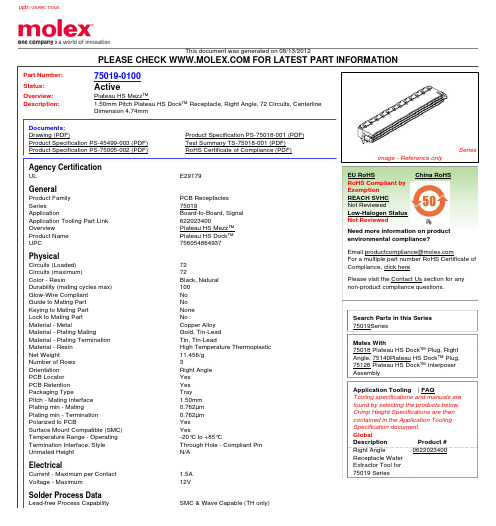
This document was generated on 08/13/2012PLEASE CHECK FOR LATEST PART INFORMATIONPart Number:75019-0100Status:ActiveOverview:Plateau HS Mezz™Description:1.50mm Pitch Plateau HS Dock™ Receptacle, Right Angle, 72 Circuits, Centerline Dimension 4.74mmDocuments:Drawing (PDF)Product Specification PS-75018-001 (PDF)Product Specification PS-45499-003 (PDF)Test Summary TS-75018-001 (PDF)Product Specification PS-75005-002 (PDF)RoHS Certificate of Compliance (PDF)Agency CertificationULE29179GeneralProduct Family PCB Receptacles Series75019ApplicationBoard-to-Board, Signal Application Tooling Part Link 622023400OverviewPlateau HS Mezz™Product Name Plateau HS Dock™UPC756054864937PhysicalCircuits (Loaded)72Circuits (maximum)72Color - ResinBlack, Natural Durability (mating cycles max)100Glow-Wire Compliant No Guide to Mating Part No Keying to Mating Part None Lock to Mating Part NoMaterial - MetalCopper Alloy Material - Plating MatingGold, Tin-Lead Material - Plating Termination Tin, Tin-LeadMaterial - Resin High Temperature Thermoplastic Net Weight11.456/g Number of Rows 3Orientation Right Angle PCB Locator Yes PCB Retention Yes Packaging TypeTray Pitch - Mating Interface 1.50mm Plating min - Mating0.762µm Plating min - Termination 0.762µm Polarized to PCBYes Surface Mount Compatible (SMC)YesTemperature Range - Operating -20°C to +85°CTermination Interface: Style Through Hole - Compliant Pin Unmated HeightN/A ElectricalCurrent - Maximum per Contact 1.5A Voltage - Maximum12VSolder Process DataLead-free Process CapabilitySMC & Wave Capable (TH only)Seriesimage - Reference onlyEU RoHSChina RoHSRoHS Compliant by Exemption REACH SVHC Not ReviewedLow-Halogen Status Not ReviewedNeed more information on product environmental compliance?Email productcompliance@For a multiple part number RoHS Certificate of Compliance, click herePlease visit the Contact Us section for any non-product compliance questions.Search Parts in this Series 75019SeriesMates With75018 Plateau HS Dock™ Plug, Right Angle, 75140Plateau HS Dock™ Plug,75126 Plateau HS Dock™ Interposer AssemblyApplication Tooling | FAQTooling specifications and manuals are found by selecting the products below.Crimp Height Specifications are then contained in the Application Tooling Specification document.GlobalDescription Product #Right Angle Receptacle Wafer Extractor Tool for 75019 Series0622023400Process Temperature max. C260Material InfoReference - Drawing NumbersProduct Specification PS-45499-003, PS-75005-002, PS-75018-001Test Summary TS-75018-001This document was generated on 08/13/2012PLEASE CHECK FOR LATEST PART INFORMATION分销商库存信息: MOLEX 0750190100。
39K100资料

Device 39K30 39K50 39K100 39K165 39K200
Notes: 3. Speed bins shown here are for commercial operating range. Please refer to Delta39K ordering information on industrial-range speed bins on page 38. 4. Self-boot solution integrates the boot PROM (flash memory) with Delta39K die inside the same package. This flash memory can endure at least 10,000 programming/erase cycles and can retain data for at least 100 years.
PIM
LB 5 LB 4
Cluster RAM
Channel RAM
LB 2 LB 3
Cluster RAM
PIM
LB 5 LB 4
Cluster RAM
Channel RAM
LB 2 LB 3
Cluster RAM
PIM
LB 5 LB 4
Cluster RAM
Channel RAM
GCLK[3:0] 4 4 4 4
元器件交易网
Delta39K™ ISR™
CPLD Family CPLDs at FPGA Densities™
Features
• High density — 30K to 200K usable gates — 512 to 3072 macrocells — 136 to 428 maximum I/O pins — Twelve dedicated inputs including four clock pins, four global I/O control signal pins and four JTAG interface pins for boundary scan and reconfigurability Embedded memory — 80K to 480K bits embedded SRAM • 16K to 96K bits of (dual-port) channel memory High speed – 233-MHz in-system operation AnyVolt™ interface — 3.3V, 2.5V,1.8V, and 1.5V I/O capability Low-power operation — 0.18-mm six-layer metal SRAM-based logic process — Full-CMOS implementation of product term array — Standby current as low as 5mA • Simple timing model — No penalty for using full 16 product terms/macrocell — No delay for single product term steering or sharing • Flexible clocking — Spread Aware™ PLL drives all four clock networks • Allows 0.6% spread spectrum input clocks • Several multiply, divide and phase shift options — Four synchronous clock networks per device — Locally generated product term clock — Clock polarity control at each register • Carry-chain logic for fast and efficient arithmetic operations • Multiple I/O standards supported — LVCMOS (3.3/3.0/2.5/1.8V), LVTTL, 3.3V PCI, SSTL2 (I-II), SSTL3 (I-II), HSTL (I-IV), and GTL+ • Compatible with NOBL™, ZBT™, and QDR™ SRAMs • Programmable slew rate control on each I/O pin • User-programmable Bus Hold capability on each I/O pin • Fully 3.3V PCI-compliant (to 66-MHz 64-bit PCI spec, rev. 2.2) • CompactPCI hot swap ready • Multiple package/pinout offering across all densities — 208 to 676 pins in PQFP, BGA, and FBGA packages — Simplifies design migration across density — Self-Boot™ solution in BGA and FBGA packages • In-System Reprogrammable™ (ISR™) — JTAG-compliant on-board programming — Design changes do not cause pinout changes • IEEE1149.1 JTAG boundary scan
40930;40931;中文规格书,Datasheet资料

0.5
0"
Sections are Interlocking
0.50" (Байду номын сангаас2.7mm) Thick Sections
Item No. 40930
Made in America
Description 24" x 36" (0.6m x 0.9m) Section 36" x 48" (0.9m x 1.2m) Section
Black Description:
This material is designed primarily to be used as a floor runner or to protect an entire room. The unique anti-fatigue dome/support cells provide extra comfort and prevent the mat from shifting on the floor. Its interlocking strip can be easily trimmed to give clean beveled edges. Statfree i™ will not trap moisture underneath. Its patented structure allows air to circulate under mat to eliminate mold or mildew problems. It will not delaminate. The Statfree i™ Floor Mat is made of 100% premium nitrile butadiene homogenous rubber material. It is heat, abrasion, and chemical resistant. Statfree i™ Exceeds ANSI/ESD S20.20 required limits of <1 x 10E9 ohms for ESD flooring and suitable for flooring component in Flooring - Footwear System as primary grounding method (<3.5 x 10E7ohms per ANSI/ESD STM97.1). Per section 3 Definitions of Floor standard ANSI/ESD STM97.1 "Conductive Flooring Material: A floor material that has a resistance to ground of less than 10E6 ohms." Statfree i™ is a manufactured rubber article and is excluded from the requirements of M.S.D.S. as defined by OSHA 29 CFR Ch. XVII §1910.1200.
MIC2044-1YTS;MIC2044-2YTS;MIC2045-1YTS;MIC2045-2YTS;MIC2044-1YTS TR;中文规格书,Datasheet资料
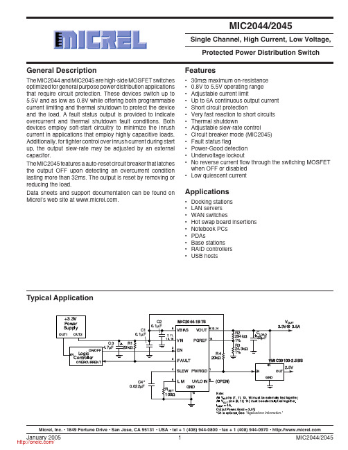
Typical Application*C4is optional.See"Applications Information."Micrel, Inc. • 1849 Fortune Drive • San Jose, CA 95131 • USA • tel + 1 (408) 944-0800 • fax + 1 (408) 944-0970 • Pin ConfigurationPWRGDEN /FAULT SLEW UVLOINILIMVIN VBIASVINPGREFVOUTVINVOUTVINGNDVOUT MIC2044/MIC204516-Pin TSSOP (TS)Ordering InformationPart NumberStandard Pb-Free Enable Circuit Breaker Package MIC2044-1BTS MIC2044-1YTS Active-High16-Pin TSSOP MIC2044-2BTS MIC2044-2YTS Active-Low16-Pin TSSOP MIC2045-1BTS MIC2045-1YTS Active-High X16-Pin TSSOP MIC2045-2BTS MIC2045-2YTS Active-Low X16-Pin TSSOPPin DescriptionPin Number Pin Name Pin Function1PWRGD Power-Good (Output):Open drain N-Channel device, active high. This pinasserts high when the voltage at PGREF exceeds its threshold.2EN Switch Enable (Input):Gate control pin of the output MOSFET available asan active high (–1) or active low (–2) input signal.3/FAULT Fault Status (Output):Open drain N-Channel device, active low. This pinindicates an overcurrent or thermal shutdown condition. For an overcurrentevent, /FAULT is asserted if the duration of the overcurrent condition lastslonger than 32ms.10GND Ground connection:Tie to analog ground.4SLEW Slew-Rate Control (Input):A capacitor connected between this pin andground will reduce (slow) the output slew-rate. The output turn-on time mustbe less than the nominal flag delay of 32ms in order to avoid nuisancetripping of the /FAULT output since V OUT must be “fully on” (i.e., within200mV of the voltage at the input) before the /FAULT signal delay elapses.The slew-rate limiting capacitor requires a 16V rating or greater, 25V isrecommended. See “Applications Information: Output Slew-Rate Adjust-ment” for further details.6ILIM Current Limit (Input):A resistor (R SET) connected from this pin to groundsets the current limit threshold as I LIMIT = CLF/R SET. CLF is the current limitfactor specified in the “Electrical Characteristics”table. For the MIC2044/45,the continuous output current range is 1A to 6A.5UVLOIN Undervoltage Lockout Adjust (Input):With this pin left open, the UVLOthreshold is internally set to 1.45V. When the switching voltage (V IN) is at orbelow 1.5V, connecting an external resistive divider to this input will lower theUVLO threshold. The total resistance of the divider must be less than 200kΩ.To disable the UVLO, tie this pin to VIN. See “Applications Information” forfurther detail.7,11,13,16VIN Switch Supply (Input):Connected to the drain of the output MOSFET. Therange of input for the switch is 0.8V to 5.5V. These pins must be externallyconnected together to achieve rated performance.9,12,14VOUT Switch (Output):Connected to the source of the output MOSFET. Thesepins must be externally connected together to achieve rated performance.8VBIAS Bias Supply (Input):This input pin supplies power to operate the switch andinternal circuitry. The input range for VBIAS is 1.6V to 5.5V. When switchedvoltage (V IN) is between 1.6V to 5.5V and the use of a single supply isdesired, connect VBIAS to VIN externally.15PGREF Power-Good Threshold (Input):Analog reference used to specify thePWRGD threshold. When the voltage at this pin exceeds its threshold, V TH,PWRGD is asserted high. An external resistive divider network is used todetermine the output voltage level at which V TH is exceeded. See the“Functional Description”for further detail. When the PWRGD signal is notutilized, this input should be tied to VOUT.Absolute Maximum Ratings (Note 1)V IN and V BIAS (6V)/FAULT, PWRGD Output Voltage (6V)/FAULT, PWRGD Output Current..............................25mA ESD Rating, Note 3Human Body Model...................................................2kV Machine Model........................................................200V Operating Ratings (Note 2)Supply VoltageV IN...............................................................0.8V to 5.5V V BIAS...........................................................1.6V to 5.5V Continuous Output Current...................................1A to 6A Ambient Temperature (T A)...........................–40°C to 85°C Package Thermal Resistance (Rθ(J-A))TSSOP................................................................85°C/WElectrical Characteristics (Note 4)V IN = V BIAS = 5V, T A = 25°C unless specified otherwise. Bold indicates –40°C to +85°C.Symbol Parameter Condition Min Typ Max Units V IN Switch Input Voltage V IN≤ V BIAS0.8 5.5V V BIAS Bias Supply Voltage 1.6 5.5V I BIAS V BIAS Supply Current - Switch OFF No load0.15µAV BIAS Supply Current - Switch ON No load300400µANote 5V EN Enable Input Voltage V IL(max) 2.4 1.5VV IH(min) 3.5 2.5V V ENHYST Enable Input Threshold Hysteresis100mV I EN Enable Input Current V EN = 0V to 5.5V–1.011µA R DS(ON)Switch Resistance V IN = V BIAS = 3V, 5V2030mΩI OUT = 500mAI LEAK Output Leakage Current Output off10µA CLF Current Limit Factor V IN = 3V, 5V, 0.5V ≤ V OUT < 0.5V IN300380460A•ΩNote 61A ≤ I OUT≤ 6AV TH PGREF Threshold V IN = V BIAS = 1.6V to 5.5V215230245mV V LATCH Output Reset Threshold V IN = 0.8V to 5.5V V IN–.0.2VV OUT rising (MIC2045)I LATCH Latched Output Off Current Output latched off (MIC2045)135mA V OL Output Low Voltage I OL (/FAULT) = 15mA0.4V (/FAULT, PWRGD)I OL (PWRGD) = 5mAI OFF/FAULT, PWRGD Off Current V FAULT = V PWRGD = 5V1µA V UV Undervoltage Lockout Threshold V IN rising 1.30 1.45 1.58VV IN falling 1.20 1.35 1.50V V UVHYST Undervoltage Lockout100mV Threshold HysteresisV UVINTH UVLO Adjust Pin Threshold Voltage V IN rising200230260mVV IN falling185215245mV V UVINHYST UVLO Adjust Pin Threshold Hysteresis15mV Overtemperature Threshold T J increasing140°CT J decreasing120°CSymbol ParameterConditionMin Typ Max Units t FLAG Flag Response Delay V IN = V BIAS = 3V, 5V 253240ms t ON Output Turn-on Delay R LOAD = 10Ω, C LOAD = 1µF 0.751 1.25ms t R Output Turn-on Rise Time R LOAD = 10Ω, C LOAD = 1µF 1.52.53.5ms t OFF Output Turn-off Delay R LOAD = 10Ω, C LOAD = 1µF 15µs t FOutput Turn-off Fall TimeR LOAD = 10Ω, C LOAD = 1µF24µsNote 1.Exceeding the absolute maximum rating may damage the device.Note 2.The device is not guaranteed to function outside its operating rating.Note 3.Devices are ESD sensitive. Handling precautions recommended. Human body model:1.5k Ω in series with 100pF.Note 4.Specification for packaged product only.Note 5.OFF is V EN < 1.0V for MIC2044/MIC2045–1 and V EN > 4.0V for MIC2044/MIC2045 –2. ON is V EN > 4.0V for MIC2044/MIC2045–1 and V EN < 1.0V for MIC2044/MIC2045 –2.Note 6.The current limit is determined as follows:I LIM = CLF/R SET .Timing DiagramsV ENV OUTV ENV OUTFigure 1. Turn-On/Turn-Off DelayV ENV OUTI OUT/FAULTFigure 2. Overcurrent Fault Response — MIC2044-2Test CircuitVS U P P L Y C U R R E N T (µA )TEMPERATURE (°C)Supply CurrentV E N (V )TEMPERATURE (°C)Enable Input Threshold(Rising)V E N (V )TEMPERATURE (°C)Enable Input Threshold(Falling)O U T P U T L E A K A G E (n A )TEMPERATURE (°C)Output Leakage CurrentO N R E S I S T A N C E (m Ω)TEMPERATURE (°C)ON ResistanceT F L A G (m s )TEMPERATURE (°C)Flag Response DelayT U R N O N D E L A Y (µs )TEMPERATURE (°C)Turn On Delayvs. TemperatureI R (m A )V OUT–V BIAS (V)V BIAS Reverse Current FlowTypical CharacteristicsU V L O T H R E S H O L D (V )TEMPERATURE (°C)UVLO ThresholdU V L O I N T H R E S H O L D (m V )TEMPERATURE (°C)UVLO Adjust Pin ThresholdS L E W P I N V O L T A G E (V )TEMPERATURE (°C)SLEW Voltage V T H (m V )TEMPERATURE (°C)Power-Good ReferenceThresholdFunctional CharacteristicsV IN =V BIAS =5.0VR LOAD =1.65V C LOAD =47m F R SET =100WTIME (500m s/div.)V IN = V BIAS = 5.0VR LOAD = 1.8ΩC LOAD = 47µF R SET = 220ΩLatched OutputTIME (5ms/div.)V IN = V BIAS = 5.0VR LOAD toggles from 2Ω to OPENC LOAD = 47µF R SET = 220Ω4.82VLatched Output ResetMIC2045TIME (50ms/div.)V IN ramps 0V to 1.8VR LOAD = 5ΩC LOAD = 47µF R SET = 220ΩUVLO ResponseTIME (2.5ms/div.)1.45VV IN = V BIAS = 5.0VR LOAD = 1.2ΩC LOAD = 47µF R SET = 100ΩCurrent Limit ResponseTIME (5ms/div.)Functional Characteristics (continued)V IN = 5.0VR LOAD =5ΩC LOAD =47µFC SLEW =0.033µFR SET =220ΩTIME (2.5ms/div.)V IN = V BIAS 5.0VR LOAD =2ΩC LOAD =47µFR SET =220ΩTIME (100ms/div.)Functional Diagram分销商库存信息:MICRELMIC2044-1YTS MIC2044-2YTS MIC2045-1YTS MIC2045-2YTS MIC2044-1YTS TR MIC2044-2YTS TR MIC2045-1YTS TR MIC2045-2YTS TR MIC2044-1BTS MIC2044-1BTS TR MIC2044-2BTS MIC2044-2BTS TR MIC2045-1BTS MIC2045-1BTS TR MIC2045-2BTS MIC2045-2BTS TR。
SQT-103-01-F-D;SQT-106-01-LM-D;SQT-110-03-F-D;SQT-120-01-F-S;中文规格书,Datasheet资料
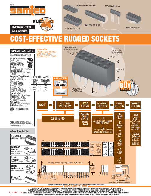
SPECIFICATIONS
For complete specifications see ?SQT
Mates with: TMMH, TMM, MTMM, MMT, TW, LTMM, ZLTMM, ESQT, TCMD
Choice of one through six rows
SQT-106-01-LM-D SQT-112-01-F-D SQT-110-01-L-Q
SQT-110-03-F-D SQT-107-01-L-T SQT-125-01-F-D
(2,29) .050 .090
(2,00) .0787
–RA OPTION
(–Q, –5 & –6 not available)
/
分销商库存信息:
SAMTEC SQT-103-01-F-D SQT-120-01-F-S SQT-110-01-LM-Q SQT-116-01-S-D
TMM/ SQT TMMH
HORIZONTAL
(2,00mm) .0787" pitch
1
NO. PINS PER ROW
LEAD STYLE
(6,35mm) .250"
PLATING OPTION
ROW OPTION
Note: Some lengths, styles and options are non-standard, non-returnable.
20°C
5.5A
(2,62mm) .103" to (5,03mm) .198" Insertion Force: (Single contact only)
40°C
5A
60°C
74435561100;中文规格书,Datasheet资料

74435561100
DATUM / DATE : 2009-11-02 Gurtspezifikation / Tape specification:
G H
SPEICHERDROSSEL WE-HCI POWER-CHOKE WE-HCI
I Rollenspezifikation / tape and reel specification:
74435561100
DATUM / DATE : 2009-11-02
SPEICHERDROSSEL WE-HCI POWER-CHOKE WE-HCI
H Induktivitätskurve / Inductance curve:
Induktivität vs Strom (typ.) Inductance vs Current (typ.)
08-09-29
Geprüft / checked
Kontrolliert / approved
Datum / date
D-74638 Waldenburg · Max-Eyth-Strasse 1 - 3 · Germany · Telefon (+49) (0) 7942 - 945 - 0 · Telefax (+49) (0) 7942 - 945 - 400 http://www.we-online.de
12,00
10,00
8,00
L (µH)
6,00
4,00
2,00
0,00 0 5 10 15 Current (A) 20 25 30 35
Freigabe erteilt / general release:
..................................................................................
0449150002;中文规格书,Datasheet资料
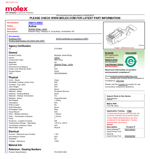
This document was generated on 09/20/2012PLEASE CHECK FOR LATEST PART INFORMATIONPart Number:44915-0002Status:ActiveOverview:Modular Plugs - JacksDescription:Modular Plug, Category 6, Long Body, Unshielded, 8/8Documents:Drawing (PDF)RoHS Certificate of Compliance (PDF)Product Specification PS-44915-003 (PDF)Agency CertificationULE107635GeneralProduct Family Modular Jacks/Plugs Series44915Component Type Wire Plug Magnetic NoOverviewModular Plugs - Jacks Performance Category 6Power over Ethernet (PoE)N/A Product Name RJ45UPC800756395548PhysicalColor - ResinClear Durability (mating cycles max)500Inverted / Top Latch N/A Jack HeightN/A Lightpipes/LEDs NoneMaterial - MetalPhosphor Bronze Material - Plating MatingGold Material - Plating Termination TinMaterial - Resin Polycarbonate Net Weight 1.504/g Orientation N/A PCB Locator No PCB Retention None Packaging Type Bag Panel MountN/A Pitch - Mating Interface1.02mm Pitch - Termination Interface 1.27mm Ports1Positions / Loaded Contacts 8/8Temperature Range - Operating -40°C to +85°C Termination Interface: Style N/A Wire/Cable TypeRound ElectricalCurrent - Maximum per Contact1.5A Grounding to Panel N/A ShieldedNo Voltage - Maximum125VMaterial InfoReference - Drawing NumbersProduct SpecificationPS-44915-003Seriesimage - Reference onlyEU RoHSChina RoHSELV and RoHS Compliant REACH SVHC Not ReviewedLow-Halogen Status Not ReviewedNeed more information on product environmental compliance?Email productcompliance@For a multiple part number RoHS Certificate of Compliance, click herePlease visit the Contact Us section for any non-product compliance questions.Search Parts in this Series 44915Series Mates With FCC 68 JacksApplication Tooling | FAQTooling specifications and manuals are found by selecting the products below.Crimp Height Specifications are then contained in the Application Tooling Specification document.GlobalDescription Product #ServiceGrade™Hand Crimp Tool -Ratchet0640160044Hand Crimp Tool 0622020500Sales Drawing SD-44915-001This document was generated on 09/20/2012PLEASE CHECK FOR LATEST PART INFORMATION分销商库存信息: MOLEX 0449150002。
760301105;中文规格书,Datasheet资料

1.1 1.02012-06-282012-04-01SStSStSStWWWürth Elektronik eiSos GmbH & Co. KGEMC & Inductive SolutionsMax-Eyth-Str. 174638 WaldenburgGermanyTel. +49 (0) 79 42 945 - 0A Dimensions: [mm]H1: Classification Reflow Profile for SMT components:H2: Classification Reflow ProfilesProfile FeaturePreheat- Temperature Min (T smin ) - Temperature Max (T smax ) - Time (t s ) from (T smin to T smax )Ramp-up rate (T L to T P )Liquidous temperature (T L )Time (t L ) maintained above T L Peak package body temperature (T p )Time within 5°C of actual peak temperature (t p )Ramp-down rate (T P to T L )Time 25°C to peak temperature Pb-Free Assembly 150°C 200°C60-180 seconds 3°C/ second max.217°C60-150 seconds See Table H320-30 seconds 6°C/ second max.8 minutes max.refer to IPC/JEDEC J-STD-020DH3: Package Classification Reflow TemperaturePB-Free Assembly PB-Free Assembly PB-Free Assembly Package Thickness< 1.6 mm 1.6 - 2.5 mm ≥ 2.5 mmVolume mm³<350260°C 260°C 250°CVolume mm³350 - 2000260°C 250°C 245°CVolume mm³>2000260°C 245°C 245°Crefer to IPC/JEDEC J-STD-020DH Soldering Specifications:I Cautions and Warnings:The following conditions apply to all goods within the product series of WE-GDTof Würth Elektronik eiSos GmbH & Co. KG:General:All recommendations according to the general technical specifications of the data sheet have to be complied with.The disposal and operation of the product within ambient conditions which probably alloy or harm the wire isolation has to be avoided.If the product is potted in customer applications, the potting material might shrink during and after hardening. Accordingly to this the product is exposed to the pressure of the potting material with the effect that the core, wire and termination is possibly damaged by this pressure and so the electrical as well as the mechanical characteristics are endanger to be affected. After the potting material is cured, the core, wire and termination of the product have to be checked if any reduced electrical or mechanical functions or destructions have occurred.The responsibility for the applicability of customer specific products and use in a particular customer design is always within the authority of the customer. All technical specifications for standard products do also apply for customer specific products.Washing varnish agent that is used during the production to clean the application might damage or change the characteristics of the wire in-sulation, the marking or the plating. The washing varnish agent could have a negative effect on the long turn function of the product.Direct mechanical impact to the product shall be prevented as the ferrite material of the core could flake or in the worst case it could break. Product specific:Follow all instructions mentioned in the datasheet, especially:•The solder profile has to be complied with according to the technical reflow soldering specification, otherwise no warranty will be sustai-ned.•Wave soldering is not applicable. Reflow soldering is recommended.•All products are supposed to be used before the end of the period of 12 months based on the product date-code, if not a 100% solderabi-lity can´t be warranted.•Violation of the technical product specifications such as exceeding the nominal rated current will result in the loss of warranty.1. General Customer ResponsibilitySome goods within the product range of Würth Elektronik eiSos GmbH & Co. KG contain statements regarding general suitability for certain application areas. These statements about suitability are based on our knowledge and experience of typical requirements concerning the are-as, serve as general guidance and cannot be estimated as binding statements about the suitability for a customer application. The responsibi-lity for the applicability and use in a particular customer design is always solely within the authority of the customer. Due to this fact it is up to the customer to evaluate, where appropriate to investigate and decide whether the device with the specific product characteristics described in the product specification is valid and suitable for the respective customer application or not.2. Customer Responsibility related to Specific, in particular Safety-Relevant ApplicationsIt has to be clearly pointed out that the possibility of a malfunction of electronic components or failure before the end of the usual lifetime can-not be completely eliminated in the current state of the art, even if the products are operated within the range of the specifications.In certain customer applications requiring a very high level of safety and especially in customer applications in which the malfunction or failure of an electronic component could endanger human life or health it must be ensured by most advanced technological aid of suitable design of the customer application that no injury or damage is caused to third parties in the event of malfunction or failure of an electronic component.3. Best Care and AttentionAny product-specific notes, warnings and cautions must be strictly observed.4. Customer Support for Product SpecificationsSome products within the product range may contain substances which are subject to restrictions in certain jurisdictions in order to serve spe-cific technical requirements. Necessary information is available on request. In this case the field sales engineer or the internal sales person in charge should be contacted who will be happy to support in this matter.5. Product R&DDue to constant product improvement product specifications may change from time to time. As a standard reporting procedure of the Product Change Notification (PCN) according to the JEDEC-Standard inform about minor and major changes. In case of further queries regarding the PCN, the field sales engineer or the internal sales person in charge should be contacted. The basic responsibility of the customer as per Secti-on 1 and 2 remains unaffected.6. Product Life CycleDue to technical progress and economical evaluation we also reserve the right to discontinue production and delivery of products. As a stan-dard reporting procedure of the Product Termination Notification (PTN) according to the JEDEC-Standard we will inform at an early stage about inevitable product discontinuance. According to this we cannot guarantee that all products within our product range will always be available. Therefore it needs to be verified with the field sales engineer or the internal sales person in charge about the current product availability ex-pectancy before or when the product for application design-in disposal is considered.The approach named above does not apply in the case of individual agreements deviating from the foregoing for customer-specific products.7. Property RightsAll the rights for contractual products produced by Würth Elektronik eiSos GmbH & Co. KG on the basis of ideas, development contracts as well as models or templates that are subject to copyright, patent or commercial protection supplied to the customer will remain with Würth Elektronik eiSos GmbH & Co. KG.8. General Terms and ConditionsUnless otherwise agreed in individual contracts, all orders are subject to the current version of the “General Terms and Conditions of Würth Elektronik eiSos Group”, last version available at .J Important Notes:The following conditions apply to all goods within the product range of Würth Elektronik eiSos GmbH & Co. KG:分销商库存信息: WURTH-ELECTRONICS 760301105。
0449140201;中文规格书,Datasheet资料

This document was generated on 08/20/2012PLEASE CHECK FOR LATEST PART INFORMATIONPart Number:44914-0201Status:ActiveOverview:Micro-Fit 3.0™ ConnectorsDescription:3.00mm Pitch Micro-Fit 3.0 CPI™ Header, Compliant Pin Interface, Dual Row, Vertical,2 Circuits, Tin (Sn) Plating, Glow Wire CompatibleDocuments:3D ModelRoHS Certificate of Compliance (PDF)Drawing (PDF)Product Literature (PDF)Product Specification PS-43045 (PDF)Agency CertificationCSA LR19980TUV R72081037ULE29179GeneralProduct Family PCB Headers Series44914ApplicationPower, Wire-to-Board Application Tooling Part Link 622008400Application Tooling Part Link 622030455Comments"High Temperature|Square Pin<P><P>This Molex product is manufactured from material that has the following ratings, tested by independent agencies:.a) A Glow Wire Ignition Temperature (GWIT) of at least 775 deg C per IEC 60695-2-13.. b) A Glow Wire Flammability Index (GWFI) above 850 deg C per IEC 60695-2-12.and hence complies with therequirements set out in the International Standard IEC 60335-1 5th edition - household and similar electrical appliances - safety, section 30 Resistance to heat and fire. <P><P> The customers using this product must determine its suitability for use in their particular application through testing or other acceptable means as described in end-product glow-wire flammability test standard IEC 60695-2-11 and any applicable product end-use standard(s). <P> If it is determined during the customer’s evaluation of suitability, that higher performance is required, please contact Molex for possible product options."OverviewMicro-Fit 3.0™ Connectors Product Literature Order No 987650-5984Product Name Micro-Fit 3.0 CPI™UPC756054637630PhysicalBreakawayNo Circuits (Loaded)2Circuits (maximum)2Color - ResinBlack Durability (mating cycles max)30Flammability94V-0Glow-Wire Compliant YesMaterial - MetalHigh Performance Alloy (HPA)Material - Plating MatingTinSeriesimage - Reference onlyEU RoHSChina RoHSELV and RoHS Compliant REACH SVHCContains SVHC: No Low-Halogen Status Low-HalogenNeed more information on product environmental compliance?Email productcompliance@For a multiple part number RoHS Certificate of Compliance, click herePlease visit the Contact Us section for any non-product compliance questions.Search Parts in this Series 44914Series Mates With 430250200Application Tooling | FAQTooling specifications and manuals are found by selecting the products below.Crimp Height Specifications are then contained in the Application Tooling Specification document.GlobalDescription Product #Compliant Pin Insertion Flat Rock Tool0622008400Removal Tool 0622030455Material - Plating Termination TinMaterial - Resin High Temperature ThermoplasticNet Weight0.480/gNumber of Rows2Orientation VerticalPCB Locator YesPCB Retention YesPackaging Type TrayPitch - Mating Interface 3.00mmPlating min - Mating 5.080µmPlating min - Termination 5.080µmPolarized to PCB YesShrouded FullyStackable NoSurface Mount Compatible (SMC)NoTemperature Range - Operating-40°C to +105°CTermination Interface: Style Through Hole - Compliant PinElectricalCurrent - Maximum per Contact5AVoltage - Maximum250VMaterial InfoReference - Drawing NumbersProduct Specification PS-43045, RPS-43045-003, RPS-43045-004Sales Drawing SD-44914-001This document was generated on 08/20/2012PLEASE CHECK FOR LATEST PART INFORMATION分销商库存信息: MOLEX 0449140201。
MIC39100中文资料

Micrel
MIC39100/39101/39102
1A Low-Voltage Low-Dropout Regulator
General Description
The MIC39100, MIC39101, and MIC39102 are 1A lowdropout linear voltage regulators that provide low-voltage, high-current output from an extremely small package. Utilizing Micrel’s proprietary Super βeta PNP™ pass element, the MIC39100/1/2 offers extremely low dropout (typically 410mV at 1A) and low ground current (typically 11mA at 1A). The MIC39100 is a fixed output regulator offered in the SOT-223 package. The MIC39101 and MIC39102 are fixed and adjustable regulators, respectively, in a thermally enhanced power 8-lead SOP (small outline package). The MIC39100/1/2 is ideal for PC add-in cards that need to convert from standard 5V to 3.3V, 3.3V to 2.5V or 2.5V to 1.8V. A guaranteed maximum dropout voltage of 630mV over all operating conditions allows the MIC39100/1/2 to provide 2.5V from a supply as low as 3.13V and 1.8V from a supply as low as 2.43V. The MIC39100/1/2 is fully protected with overcurrent limiting, thermal shutdown, and reversed-battery protection. Fixed voltages of 5.0V, 3.3V, 2.5V, and 1.8V are available on MIC39100/1 with adjustable output voltages to 1.24V on MIC39102.
0190190011;中文规格书,Datasheet资料
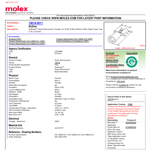
This document was generated on 08/13/2012PLEASE CHECK FOR LATEST PART INFORMATIONPart Number:19019-0011Status:ActiveDescription:Avikrimp™ Quick Disconnect, Female, for 18-22 (0.80-0.35mm²) Wire, Mylar Tape, Tab 4.75 x 0.51mmDocuments:Drawing (PDF)Product Specification PS-19902-015 (PDF)Product Specification PS-19902-011 (PDF)RoHS Certificate of Compliance (PDF)Product Specification PS-19902-014 (PDF)Agency CertificationCSA LR18689ULE79133GeneralProduct Family Quick Disconnects Series19019Crimp Quality Equipment YesProduct Name Avikrimp™Type Quick Disconnect UPC800753037908PhysicalBarrel Type Closed Flammability 94V-2GenderFemale Glow-Wire Compliant NoInsulationNylon (PA)Lock to Mating Part None Material - Metal Brass Net Weight 0.716/g OrientationStraightPackaging TypeAdhesive Tape on Reel Polarized to Mating Part NoTab Thickness 0.51mm Tab Width4.75mmTemperature Range - Operating -65°C to +105°C Wire Insulation Diameter 2.90mm max.Wire Size AWG 18, 20, 22Wire Size mm²0.35 - 0.80ElectricalVoltage - Maximum300V Material InfoOld Part NumberAA-8137TReference - Drawing NumbersProduct Specification PS-19902-011, PS-19902-014, PS-19902-015Sales DrawingSD-19019-001Seriesimage - Reference onlyEU RoHSChina RoHSELV and RoHS Compliant REACH SVHC Not ReviewedLow-Halogen Status Not ReviewedNeed more information on product environmental compliance?Email productcompliance@For a multiple part number RoHS Certificate of Compliance, click herePlease visit the Contact Us section for any non-product compliance questions.Search Parts in this Series 19019SeriesApplication Tooling | FAQTooling specifications and manuals are found by selecting the products below.Crimp Height Specifications are then contained in the Application Tooling Specification document.GlobalDescription Product #Mini-Mac™Applicator 0638850800Crimp Dies for MTA-100 Tape Applicator used in 3BF Press, MTA-105Tape Applicator used in TM-2000™ Press,and ATP-301 Air Crimping Press for Mylar Tape Mounted Terminals0192880048This document was generated on 08/13/2012PLEASE CHECK FOR LATEST PART INFORMATION分销商库存信息: MOLEX 0190190011。
0190160098;中文规格书,Datasheet资料

This document was generated on 08/13/2012PLEASE CHECK FOR LATEST PART INFORMATIONPart Number:19016-0098Status:ActiveDescription:Krimptite™ Quick Disconnect, Female, for 24-26 (0.20-0.12mm²) Wire, Box, Tab 4.75 x 0.51mmDocuments:Drawing (PDF)Product Specification PS-19902-013 (PDF)Product Specification PS-19902-011 (PDF)RoHS Certificate of Compliance (PDF)GeneralProduct Family Quick Disconnects Series19016CommentsButted Seam Crimp Quality Equipment YesProduct Name Krimptite™Type Quick Disconnect UPC800755047585PhysicalBarrel Type Closed GenderFemale Glow-Wire Compliant No InsulationNone Lock to Mating Part None Material - Metal Brass Net Weight 0.360/g OrientationStraight Packaging TypeBag Polarized to Mating Part NoTab Thickness 0.51mm Tab Width4.75mmTemperature Range - Operating Per Wire Specification Wire Size AWG 24, 26Wire Size mm²0.12 - 0.20ElectricalVoltage - MaximumPer Wire Specification Material InfoOld Part NumberM-1136Reference - Drawing NumbersProduct Specification PS-19902-011, PS-19902-013Sales DrawingSD-19016-004Seriesimage - Reference onlyEU RoHSChina RoHSELV and RoHS Compliant REACH SVHCContains SVHC: No Low-Halogen Status Low-HalogenNeed more information on product environmental compliance?Email productcompliance@For a multiple part number RoHS Certificate of Compliance, click herePlease visit the Contact Us section for any non-product compliance questions.Search Parts in this Series 19016SeriesApplication Tooling | FAQTooling specifications and manuals are found by selecting the products below.Crimp Height Specifications are then contained in the Application Tooling Specification document.GlobalDescription Product #Hand Crimp Tool 0640030400Crimp Head for the AT-200™ Pneumatic Hand Tool0640070400This document was generated on 08/13/2012PLEASE CHECK FOR LATEST PART INFORMATION/分销商库存信息: MOLEX 0190160098。