PNOZ m EF 8DI2DO安全压机监控模块
PNOZ m EF 8DI4DO操作手册说明书

PNOZ m EF 8DI4DO}Configurable control systems PNOZmulti 2This document is a translation of the original document.All rights to this documentation are reserved by Pilz GmbH & Co. KG. Copies may be made for internal purposes. Suggestions and comments for improving this documentation will be gratefully received.Pilz®, PIT®, PMI®, PNOZ®, Primo®, PSEN®, PSS®, PVIS®, SafetyBUS p®,SafetyEYE®, SafetyNET p®, the spirit of safety® are registered and protected trademarks of Pilz GmbH & Co. KG in some countries.SD means Secure Digital1.2Using the documentation4 1.3Definition of symbols42.2Unit features6 2.3Front view73.2System requirements8 3.3Safety regulations8 3.3.1Use of qualified personnel8 3.3.2Warranty and liability9 3.3.3Disposal9 3.3.4For your safety94.2Functions10 4.3System reaction time10 4.4Block diagram105.2Dimensions in mm11 5.3Connecting the base unit and expansion modules116.2Connection13 6.3Download modified project to the PNOZmulti system1410.2Accessories221Introduction1.1Validity of documentationThis documentation is valid for the product PNOZ m EF 8DI4DO. It is valid until new docu-mentation is published.This operating manual explains the function and operation, describes the installation andprovides guidelines on how to connect the product.1.2Using the documentationThis document is intended for instruction. Only install and commission the product if youhave read and understood this document. The document should be retained for future ref-erence.1.3Definition of symbolsInformation that is particularly important is identified as follows:NOTICEThis describes a situation in which the product or devices could be dam-aged and also provides information on preventive measures that can betaken. It also highlights areas within the text that are of particular import-ance.INFORMATIONThis gives advice on applications and provides information on special fea-tures.2Overview2.1Scope of supply}Expansion module PNOZ m EF 8DI4DO}Jumper2.2Unit featuresUsing the product PNOZ m EF 8DI4DO:Expansion module for connection to a base unit from the configurable control systemPNOZmulti 2 .The product has the following features:}Can be configured in the PNOZmulti Configurator}Semiconductor outputs:4 safety outputsDepending on the application, up to PL e of EN ISO 13849-1 and up to SIL CL 3 of ENIEC 62061}8 inputs for connecting, for example:–E-STOP pushbutton–Two-hand button–Safety gate limit switch–Start button–Light beam devices–Scanner–Enabling switch–PSEN–Operating mode selector switch}LED for:–Error messages–Diagnostics–Supply voltage–Output circuits–Input circuits}Test pulse outputs used to monitor shorts across the inputs}Monitoring of shorts between the safety outputs}Plug-in connection terminals:Either spring-loaded terminal or screw terminal available as an accessory (see orderreference)}Please refer to the document "PNOZmulti System Expansion" for the PNOZmulti base units that can be connected.2.3Front viewKey:}0 V, 24 V: Supply connections}Inputs I0 – I7}Outputs O0 – O3}LEDs:–POWER–Run–Diag–Fault–I Fault–O Fault3Safety3.1Intended useThe expansion module may only be connected to a base unit from the configurable systemPNOZmulti 2 (please refer to the document "PNOZmulti System Expansion" for details ofthe base units that can be connected).The configurable system PNOZmulti 2 is used for the safety-related interruption of safetycircuits and is designed for use in:}Emergency stop equipment}Safety circuits in accordance with VDE 0113 Part 1 and EN 60204-1The following is deemed improper use in particular:}Any component, technical or electrical modification to the product}Use of the product outside the areas described in this manual}Use of the product outside the technical details (see Technical details [ 17]).NOTICEEMC-compliant electrical installationThe product is designed for use in an industrial environment. The productmay cause interference if installed in other environments. If installed in otherenvironments, measures should be taken to comply with the applicablestandards and directives for the respective installation site with regard to in-terference.3.2System requirementsPlease refer to the "Product Modifications PNOZmulti" document in the "Version overview"section for details of which versions of the base unit and PNOZmulti Configurator can beused for this product.3.3Safety regulations3.3.1Use of qualified personnelThe products may only be assembled, installed, programmed, commissioned, operated,maintained and decommissioned by competent persons.A competent person is someone who, because of their training, experience and current pro-fessional activity, has the specialist knowledge required to test, assess and operate thework equipment, devices, systems, plant and machinery in accordance with the generalstandards and guidelines for safety technology.It is the company’s responsibility only to employ personnel who:}Are familiar with the basic regulations concerning health and safety / accident preven-tion}Have read and understood the information provided in this description under "Safety"}And have a good knowledge of the generic and specialist standards applicable to the specific application.3.3.2Warranty and liabilityAll claims to warranty and liability will be rendered invalid if}The product was used contrary to the purpose for which it is intended}Damage can be attributed to not having followed the guidelines in the manual}Operating personnel are not suitably qualified}Any type of modification has been made (e.g. exchanging components on the PCB boards, soldering work etc.).3.3.3Disposal}When decommissioning, please comply with local regulations regarding the disposal of electronic devices (e.g. Electrical and Electronic Equipment Act).3.3.4For your safetyThe unit meets all the necessary conditions for safe operation. However, you should alwaysensure that the following safety requirements are met:}This operating manual only describes the basic functions of the unit. The expanded functions are described in the PNOZmulti Configurator's online help. Only use thesefunctions once you have read and understood the documentations.}Do not open the housing or make any unauthorised modifications.}Please make sure you shut down the supply voltage when performing maintenance work (e.g. exchanging contactors).Function description4Function description4.1Integrated protection mechanismsThe relay conforms to the following safety criteria:}The circuit is redundant with built-in self-monitoring.}The safety function remains effective in the case of a component failure.}The safety outputs are tested periodically using a disconnection test.4.2FunctionsThe expansion module provides additional inputs and additional semiconductor outputs.The function of the inputs and outputs on the control system depends on the safety circuitcreated using the PNOZmulti Configurator. A chip card is used to download the safety cir-cuit to the base unit. The base unit has 2 microcontrollers that monitor each other. Theyevaluate the input circuits on the base unit and expansion modules and switch the outputson the base unit and expansion modules accordingly.The online help on the PNOZmulti Configurator contains descriptions of the operatingmodes and all the functions of the PNOZmulti control system, plus connection examples.4.3System reaction timeCalculation of the maximum reaction time between an input switching off and a linked out-put in the system switching off is described in the document "PNOZmulti System Expan-sion".4.4Block diagram5Installation5.1General installation guidelines}The unit should be installed in a control cabinet with a protection type of at least IP54.}Fit the safety system to a horizontal mounting rail. The venting slots must face upward and downward. Other mounting positions could damage the safety system.}Use the locking elements on the rear of the unit to attach it to a mounting rail.}In environments exposed to heavy vibration, the unit should be secured using a fixing element (e.g. retaining bracket or end angle).}Open the locking slide before lifting the unit from the mounting rail.}To comply with EMC requirements, the mounting rail must have a low impedance con-nection to the control cabinet housing.}The ambient temperature of the PNOZmulti units in the control cabinet must not exceed the figure stated in the technical details, otherwise air conditioning will be required.NOTICEDamage due to electrostatic discharge!Electrostatic discharge can damage components. Ensure against dischargebefore touching the product, e.g. by touching an earthed, conductive sur-face or by wearing an earthed armband.5.2Dimensions in mm5.3Connecting the base unit and expansion modulesConnect the base unit and the expansion modules as described in the operating manualsfor the base modules.}The terminator must be fitted to the last expansion module}Install the expansion module in the position configured in the PNOZmulti Configurator.The position of the expansion modules is defined in the PNOZmulti Configurator. The ex-pansion modules are connected to the left or right of the base unit, depending on the type.Please refer to the document "PNOZmulti System Expansion" for details of the number of modules that can be connected to the base unit and the module types.6Commissioning6.1General wiring guidelinesThe wiring is defined in the circuit diagram of the PNOZmulti Configurator.Please note:}Information given in the Technical details [ 17] must be followed.}Use copper wire that can withstand 75° C.6.2ConnectionSupply voltageConnection examples for the input circuitConnection examples for semiconductor outputs*Two loads may be connected to each safety output with advanced fault detection, even onapplications in accordance with EN IEC 62061, SIL CL 3. Prerequisite: Feedback loop isconnected, shorts across contacts and external power sources are excluded (e.g. throughseparate multicore cables). Please note that, in the event of an error in the feedback loop,the safety system switches to a safe condition and shuts down all the outputs.Connection examples for feedback loop6.3Download modified project to the PNOZmulti systemAs soon as an additional expansion module has been connected to the system, the projectmust be amended using the PNOZmulti Configurator. Proceed as described in the operat-ing instructions for the base unit.NOTICEFor the commissioning and after every program change, you must checkwhether the safety devices are functioning correctly.Operation7OperationWhen the supply voltage is switched on, the PNOZmulti safety system copies the configur-ation from the chip card.The LEDs “POWER”, “DIAG”, “FAULT”, “IFAULT” and “OFAULT” will light up on the baseunit.7.1MessagesLegendLED onLED flashesLED off8Technical detailsApprovals BG, CCC, CE, GOST, TÜV, cULus Listed Application range Failsafefor Supply to the SC outputsVoltage24 VKind DCVoltage tolerance-20 %/+25 %Current load capacity at UB8,0 APotential isolation yesSupply voltagefor Module supplyinternal Via base unitVoltage24,0 VKind DCCurrent consumption39 mAPower consumption1,0 WMax. power dissipation of module4,50 WStatus indicator LEDInput voltage in accordance with EN 61131-2 Type 124 V DCInput current at rated voltage 5 mAInput current range2,5 - 5,3 mAPulse suppression0,5 msMaximum input delay8 msductor outputs4Switching capabilityVoltage24 VTyp. output current at "1" signal and rated voltage ofsemiconductor output2,00 APermitted current range0,00 - 2,50 AResidual current at "0" signal0,05 mAMax. transient pulsed current12 AMax. capacitive load 1 µFMax. internal voltage drop500 mVMax. duration of off time during self test330 µsSwitch-off delay 3 msIn accordance with the standard EN 60068-2-14Temperature range0 - 60 °CForced convection in control cabinet off55 °CStorage temperatureIn accordance with the standard EN 60068-2-1/-2Temperature range-25 - 70 °CClimatic suitabilityIn accordance with the standard EN 60068-2-30, EN 60068-2-78 Condensation during operation Not permittedEMC EN 61131-2VibrationIn accordance with the standard EN 60068-2-6Frequency5,0 - 150,0 HzAcceleration1gShock stressIn accordance with the standard EN 60068-2-27Acceleration15gDuration11 msMax. operating height above sea level2000 mAirgap creepageIn accordance with the standard EN 61131-2Overvoltage category IIPollution degree2Rated insulation voltage30 VProtection typeIn accordance with the standard EN 60529Mounting area (e.g. control cabinet)IP54Housing IP20Potential isolation between SC output and system voltage Type of potential isolation Basic insulationDIN railTop hat rail35 x 7,5 EN 50022Recess width27 mmMax. cable lengthMax. cable length per input1,0 kmBottom PC Front PC TopPCConnection type Spring-loaded terminal, screw terminal Mounting typeplug-inConductor cross section with screw terminals 1 core flexible0,25 - 2,50 mm², 24 - 12 AWG 2 core with the same cross section, flexible without crimp connectors or with TWIN crimp connectors 0,20 - 1,50 mm², 24 - 16 AWG Torque setting with screw terminals0,50 NmConductor cross section with spring-loaded terminals:Flexible with/without crimp connector0,20 - 2,50 mm², 24 - 12 AWG Spring-loaded terminals: Terminal points per connec-tion2Stripping length with spring-loaded terminals 9 mm Dimensions Height 101,4 mm Width 22,5 mm Depth 120,0 mm Weight105 gWhere standards are undated, the 2012-04 latest editions shall apply.8.1Safety characteristic dataNOTICEYou must comply with the safety-related characteristic data in order to achieve the required safety level for your plant/machine.SC inputs 2-channel PL e Cat. 4SIL CL 34,27E-1120SC inputs1-ch., pulsedlight barrier PL eCat. 4SIL CL 32,10E-1020with ad-vanced faultdetection PL e Cat. 4SIL CL 32,12E-1120SC outputs1-channel PL d Cat. 2SIL CL 22,29E-1020SC outputs2-channel PL e Cat. 4SIL CL 31,64E-1020All the units used within a safety function must be considered when calculating the safetycharacteristic data.INFORMATIONA safety function's SIL/PL values are not identical to the SIL/PL values ofthe units that are used and may be different. We recommend that you usethe PAScal software tool to calculate the safety function's SIL/PL values.Supplementary data9Supplementary data9.1Permitted ambient temperature Tamb dependent on the totalcurrent IsumOrder reference10Order reference 10.1Product10.2AccessoriesConnection terminalsTerminator, jumperSupportTechnical support is available from Pilz round the clock. Americas Brazil+55 11 97569-2804Canada+1 888-315-PILZ (315-7459)Mexico+52 55 5572 1300USA (toll-free)+1 877-PILZUSA (745-9872)Asia China+86 21 60880878-216 Japan+81 45 471-2281South Korea +82 31 450 0680Australia +61 3 95446300Europe Austria+43 1 7986263-0Belgium, Luxembourg +32 9 3217575France+33 3 88104000Germany+49 711 3409-444Ireland+353 21 4804983Italy+39 0362 1826711Scandinavia +45 74436332Spain+34 938497433Switzerland +41 62 88979-30The Netherlands +31 347 320477Turkey+90 216 5775552United Kingdom +44 1536 462203You can reach our international hotline on: +49 711 3409-444 ****************C M S E ®, I n d u r a N E T p ®, P A S 4000®, P A S c a l ®, P A S c o n fi g ®, P i l z ®, P I T ®, P L ID ®, P M C p r i m o ®, P M C p r o t e g o ®, P M C t e n d o ®, P M D ®, P M I ®, P N O Z ®, P r i m o ®, P SE N ®, P S S ®, P V I S ®, S a f e t y B U S p ®, S a f e t y E Y E ®, S a f e t y N E T p ®, T h E S P I r I T O f S A f E T Y ® a r e r e g i s t e r e d a n d p r o t e c t e d t r a d e m a r k s o f P i l z G m b h & C o . K G i n s o m e c o u n t r i e s . W e w o u l d p o i n t o u t t h a t p r o d u c t f e a t u r e s m a y v a r y f r o m t h e d e t a i l s s t a t e d i n t h i s d o c u m e n t , d e p e n d i n g o n t h e s t a t u s a t t h e t i m e o f p u b l i c a t i o n a n d t h e s c o p e o f t h e e q u i p m e n t . W e a c c e p t n o r e s p o n s i b i l i t y f o r t h e v a l i d i t y , a c c u r a c y a n d e n t i r e t y o f t h e t e x t a n d g r a p h i c s p r e s e n t e d i n t h i s i n f o r m a t i o n . P l e a s e c o n t a c t o u r T e c h n i c a l S u p p o r t i f y o u h a v e a n y q u e s t i o n s .Pilz develops environmentally-friendly products using ecological materials and energy-saving technologies. Offices and production facilities are ecologically designed, environmentally-aware and energy-saving. So Pilz offers sustainability, plus the security of using energy-efficient products and environmentally-friendly solutions.Pilz Gmbh & Co. KG felix-Wankel-Straße 2 73760 Ostfildern, Germany Tel.: +49 711 3409-0 fax: +49 711 3409-133 100X X X X -D E -0X 0-0-1-3-000, 2015-00 P r i n t e d i n G e r m a n y © P i l z G m b h & C o . K G , 20151002661-E N -03, 2016-02 P r i n t e d i n G e r m a n y © P i l z G m b H & C o . K G , 2015。
系列主令控制器

c2 平头或凸头按钮手柄:该手柄机构与c1) 相同,但操作头是固定的,只有按钮可以 改变相关触点状态。
6
术语名词 (续)
方向
2 方向
运动机构
4 方向
2 方向同步
1 副运动机构 AB
手柄运动类型
2 副运动机构 AB和CD
电气触点 闭合顺序图
操作周期
XK系列主令控制器
控制杆从零位可被移动的方向,2方向或4方向,南北方向 (A-B) 和/或东西方向 (C-D)某些限位套筒允许控制杆在两个方向同时运动,如东+南 (B+C)。
一副运动机构包含两个运动方向,成一条直线,在零位的两侧,如:南北运动机构 (A-B)
IEC 337-1, NF C 63-140, VDE 0660第2部分
XKBA:CSA ~300 V“重载”,c“标准负载”, ASE:最大500 mV, 最大10 A, 最大100 VA,USSR,CCC 标准“TC”处理
贮藏 运行
˚C
- 40...+ 70
˚C
- 20...+ 70
所有位置
6 gn (从1到70 Hz)
每个方向有三种不同类型的手柄运动方式可以选择 1 有档位手感,手柄自保持 控制手柄从零位有级地向最大偏移方向运动,保持机构使控制杆能够在手柄释放 后,保持在相应的档位。 2 有档位手感,手柄自动回零 控制手柄从零位有级地向最大偏移方向运动,弹簧机构使控制杆能够在手柄释放 后,返回到中心零位。 3 无档位手感,手柄自动回零 控制手柄从零位无级地向最大偏移方向运动,弹簧机构使控制杆能够在手柄释放 后,返回到中心零位。
皮尔磁:实战机械压机的安全控制
│31皮尔磁:实战机械压机的安全控制••皮尔磁工业自动化(上海)有限公司机械压力机安全1. 危险性在机械行业的各类机器中,机械压力机一直以来都是危险性极高的机器之一,每年由于机器本身没有完善的安全防护而使得操作人员在使用机器时受伤的情况屡见不鲜。
机械压力机在运行时可能会导致挤压、摩擦、拖曳等危险,这些危险一旦发生,将导致严重的人员伤害。
2. 安全强制标准因为机械压力机的危险性之高,国际上有专门针对它的安全标准——EN 692。
该标准针对机械压机做出了明确的安全要求。
国内也参照EN 692的压机标准,结合自身的特点,制定并推行了最新的强制性国标—— GB 27607-2011。
3. 皮尔磁:解决方案今天,我们将结合GB 27607-2011标准中对于机械压机控制系统相关安全要求,使用皮尔磁PNOZ m B1基础模块搭配PNOZ m EF 8DI2DOT压机扩展模块,来实现压机的完整安全控制系统设计。
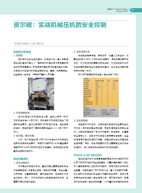
安全功能设计1. 安全功能设计对于单台机械压机来说,整台机器上需要监控的安全功能通常包括:紧急停止按钮、联锁防护装置、安全光幕、双手按钮、光幕屏蔽信号、模式选择开关、主控电机及安全双联阀。
另外,对于机械压机这类特定结构的机械,还需要对其凸轮进行监控。
2. 安全功能冗余标准规定急停按钮,联锁防护,光幕以及安全阀,均需达到GB/T 16855.1-2008中的4类要求,满足该等级要求的元件,它们的任何故障都应被检测到,不应存在由于元件发生故障而导致安全功能丢失的情况。
因此安全元器件都采用冗余输入形式。
我们将可能遇到的安全输入输出点做了统计:3. 安全双联阀在控制执行机构中,双联阀是机械压机的主要安全执行机构,用于驱动离合制动器,使压机滑块启动或停止运行。
双联阀的通断除了取决于如急停、安全联锁、光幕等安全信号之外,还取决于机械压力信号等标准信号,这些标准信号可通过标准PLC采集,并通过现场总线传递给安全控制器。
安迪桑(EATON)电路保护器和密封式电子开关安装说明书

Installation Instructions for R-Frame Circuit Breakers and Molded Case SwitchesContentsDescription Page1. Introduction (2)2. Installation (5)3. Manual Operation (6)4. Inspection and Field Testing (7)2Instruction Leaflet IL29C107NE ective January 2012Installation Instructions for R-FrameCircuit Breakers and Molded Case SwitchesEATON CORPORATIONWARNINGWARNING DO NOT ATTEMPT TO INSTALL ORPERFORM MAINTENANCE ON EQUIPMENT WHILE IT IS ENERGIZED. DEATH, SEVERE PERSONAL INJURY, OR SUBSTANTIAL PROPERTY DAMAGE CAN RESULT FROMCONTACT WITH ENERGIZEDEQUIPMENT. ALWAYS VERIFY THAT NO VOLTAGE IS PRESENT BEFORE PROCEEDING WITH THE TASK AND ALWAYS FOLLOW GENERALLY ACCEPTED SAFETY PROCEDURES.MISAPPLICATION OR MISINSTALLATION OF ITS PRODUCTS.The user is cautioned to observe all recommendations, warnings, and cautions relating to the safety of personnel and equipment as well as all general and local health and safety laws, codes, and procedures.The recommendations a nd information contained herein are based on Eaton experience and judgment, but should not be considered to be all -inclusive or coveringevery application or circumstance which may arise. Ifany questions arise, contact Eaton for further information or instructions.EATON IS NOT LIABLE FOR THEF 11TFig. 1-1 R -Frame Circuit BreakerFrame with Digitrip RMS Trip Unit Installed 1. INTRODUCTION 1.1 General InformationThe R -Frame circuit breakers (Fig. 1-1) have interchangeable electronic trip units rated 2500A maximum. Refer to Table 2-2 for allThis instruction leaflet (IL) gives procedures for installation and field testing of R-Frame circuit breakers. For this publication, the term circuitavailable trip unit rating plug ratings. R-Frame breakers and molded case switches are listedin accordance with Underwriters Laboratories, Inc.S tandard U L489 and s atisfy t he r equirements of the International Electrotechnical Commission Recommendations No. IEC 60947-2. For more information, see Selection Data 29-120R.breaker shall also include the molded case switch.3Instruction Leaflet IL29C107NE ective January 2012Installation Instructions for R-Frame Circuit Breakers and Molded Case SwitchesEATON CORPORATION Fig.2-1Terminal InstallationStep 1.Install OneRear Connector Step 2.Install One Set of Heat SinksStep 3.Repeat Steps One and Two to Adjacent PolesFig.2-22500A RearConnector Instructions4Instruction Leaflet IL29C107NE ective January 2012Installation Instructions for R-FrameCircuit Breakers and Molded Case SwitchesEATON CORPORATIONRequired and shipped with 100% rated frames Available Trip Unit Rating Plug Adjustable Long Delay up(Standard)Setting Range Using0.1 to 0.5 2 to 24 X The current pick -up setting is a multiple of the fixed rating plug value or setting of the adjustable rating plug. Adjustable Rating Plugs are not available for Digitrip RMS 510, 610, 810, 910, 750 and 1050 Trip Units.The adjustable long time pick -up adjustcment permits a pick-- .e u l a v g u l p g n i t a r e h t f o o t %001 05 f o e g n a r p u This defines the I, rating which is both the long delay and short delay protection. A 1600A c ircuit breaker can provide 400A circuit protection when e quipped with a Digitrip RMS 510,610, 810,910,750 or 1050 Trip Unit with theadjustable long time pick -up adjustment set to .5 with an 800A rating plug. A 2000A c ircuit breaker can likewise provide 500A circuit protection.In m ultiples of the I , rating.Rating plugsfor the Digitrip RMS 510, 610.810.910. 750 or 1050 Trip Unit are marked 50 Hz/60 Hz.Torque Valves Lb-in (N.m)Catalog NumberMaximumBreaker Amps Terminal Body Material HardwareAWG/MCM Wire Range/No. Conductors Metric Wire Range mm² Wire Type Wire Lug Mtg.HardwareTA1600RD 1600 Aluminum English 500-1000(4) 300-500 Cu/Al 550 (62) 300 (34 T1600RD 1600 Copper English 1-600 (4) 50-300 Cu 375 (42) 300 (34) TA1600RDM 1600 Aluminum Metric 500-1000(4) 300-500 Cu/Al 550 (62) 300 (34) Wire TerminalsT1600RDM 1600 Copper Metr ic 1-600 (4)50-300 Cu 375 (42) 300 (34)B2016RD 2000 Copper English 180 (20) Rear Connectors B2016RDM 2000 Copper Metric 180 (20) B2016RDL2000 Copper English180 (20)Rear Connectors B2016RDLM2000 Copper Metric 180- (20) B2500RD 2500 Copper English 180 (20) Rear ConnectorsB2500RDM2500CopperMetric180 (20)Required and shipped with 2500 Amp frames.Table 2-1. Terminal TypesInstruction Leaflet IL29C107NInstallation Instructions for R-FrameCircuit Breakers and Molded Case Switches5EATON CORPORATION The current pick-up setting is a multiple of the I r setting.6Instruction Leaflet IL29C107NInstallation Instructions for R-Frame Circuit Breakers and Molded Case SwitchesEATON CORPORATION 1.2100Percent Rated R -Frame Circuit Breakers CRD and CRDC circuit breakers are suitable for continu -ous operation at 100percent of the frame rating if used with the supplied rear connectors B2016EDL and in an enclosurewhich measures at least 21.5in.high x 18 in. wide x 13 in. deep.Ventilation is not required in an enclo -sure having these minimum dimensions. If cable connec -tions are made to these rear connectors, use only 90°Cwire with based on 75°C conductors and copper onlyor terminals.1.32500Amp R -Frame Circuit BreakersWhen placed in an enclosure with minimum size of 26in.x 18 in. x 10 in., the enclosure cover must be insulated with a barrier on the line end having minimum dimensions of 18 in. x 8 in. x 1/32 in..438 (11.13)Dia (4Use 375Dia.BoltsMounting Circuit Breaker7Breaker HandleI4-Pole 19.000(482.60)3-Pole 14.500(368.30)Dimensions Inches (Millimeters)Fig.2-3CircuitBreaker Mounting Bolt Drilling PlansCircuit Circuit Breaker Breaker HandleHandle. . . . . . . .. 5.094(129.39))Circuit Breaker Handle17.406(327.81)(442.11)2.INSTALLATIONThe installation procedure consists of inspecting thecircuit breaker and, as applicable, installingthe trip unit and rating plug,accessories,and terminals; mounting the circuit breaker; connecting the line and load conductors; and torquing terminals. Circuit breakers, rating plugs, accessories, mounting hardware, and unmounted termi -nals may be supplied in separate packages. T o install the circuit breaker, perform the following steps.Note:If required, internal accessory installation in any type of circuit breaker should be done before the circuit breaker is mounted and connected.Refer to individual accessory instruction leaflets.2-1.Make sure that the circuit breaker is suitable for theintended installation by comparing nameplate data with existing equipment ratings and system require -ments. Inspect the circuit breaker for completeness,and check for damage before mounting.2-2.Remove cover screws and cover.Note:The breaker is equipped with a Cover Interlock feature,so that when the cover is removed,thebreaker will trip and cannot be reset or operated until the cover is replaced and screwed down securely.Note:Instructions for installing the trip unit rating plug and accessories in the R -Frame circuit breaker are supplied with each item.2-3.If not already installed, mount trip unit rating plug andaccessories (if required)in circuit breaker frame.2-4. Re -install cover and secure with pan -head screwsprovided. Torque cover screws to 24 in-lbs. If not already installed,mount terminals as shown inFig. 2-1or 2-2.If warning label is supplied with the terminal,place on upper portion of circuit breakercover.WARNINGVOLTAGES IN ENERGIZED EQUIPMENT CAN CAUSE DEATH OR SEVERE PERSONAL INJURY.BEFORE MOUNTING THE CIRCUIT BREAKER IN ANELECTRICALSYSTEM,MAKE SURETHERE IS NO VOLTAGE PRESENTWHEREWORK IS TO BE PERFORMED.SPECIAL ATTENTION SHOULD BE PAID TO REVERSE FEED APPLICATIONS ENSURE NOVOLTAGE IS PRESENT.3 and 4-Pole Circuit BreakersWhen installing the R-Frame 2500 amp breaker at80% of the full rating and inside an enclosure, it is necessary to use coated or painted buswork.Radius(If Required)Dimensions in Inches (Millimeters)Fig. 2-4 Circuit Breaker Escutcheon Dimensions for2-5.7Instruction Leaflet IL29C107NInstallation Instructions for R-FrameCircuit Breakers and Molded Case SwitchesEATON CORPORATION 2-6. To mount the circuit breaker,perform the followingsteps:a.For individual surface mounting, drill mounting panel using the drilling plan shown in Fig. 2-3.For dead -front cover applications,cut out cover to correct escutcheon dimensions, see Fig. 2-4.If circuit breaker includes factory or field installed internal accessories, make sure accessory wiring is accessible when the circuit breaker is mounted.b.Note:Labels with accessory connection schematic diagrams are provided on the side of the circuitbreaker.A note should be made of the diagrams if the labels cannot be seen when the circuit breaker is mounted.c. Position c ircuit breaker on mounting surface.Install circuit breaker (mounting hardware notsupplied).CAUTIONOVERHEATING CAN CAUSE NUISANCE TRIPPING AND DAMAGETOTHECIRCUIT BREAKER.WHEN ALUMINUMCONDUCTORS ARE USED, THE APPLICATION OF A SUITABLE JOINT C OMPOUND IS RECOMMENDED TO REDUCE THE POSSIBILITY O F TERMINALOVERHEATING .2-7. Connect line and load conductors and accessoryNote:The circuit breaker is suitable for reverse feed application.Observe warning label on cover before attempting to removecover.the circuit breaker is installed, check all mount -ing hardware and terminal connecting hardware for correct torque loading. T orque values for line/load terminals are given in Table 2-1and on the circuit breaker nameplates.leads.3.MANUALOPERATIONNote:The trip unit and rating plug must be installed before attempting to close the circuit breaker.Manual operation of the circuit breaker is controlled by the circuit breaker handle and the PUSH -TO -TRIP button. The circuit breaker handle has three positions, two of which are shown on the cover with raised lettering to indicate ON and OFF.On the handle,ON,OFF,and tripColor: Red -ON-1I I IInternational Trip Unit SymbolsI -ON Rating PlugFig.3-1CircuitBreaker Manual Controlsare also shown by a color -coded strip for each circuitbreaker handle position: red for ON,white for tripped, and green for OFF.(See Fig. 3-13.1Circuit Breaker ResetAfter an automatic or accessory initiated trip,or a manual PUSH -TO -TRIP operation, the circuit breaker is reset by moving the circuit breaker handle to the extreme OFF position.Note:No circuit breaker should be reclosed until the cause of trip is known and the situation rectified.PUSH -TO -TRIP ButtonThe PUSH -TO -TRIP button checks the circuit breaker tripping function and may be used to periodically exercise the operating mechanism. T he button is designed to be operated by finger pressure. Interchangeable Trip UnitsInformationfor the Digitrip RMS trip units is shown in Table 2-2.For additional information on interchangeable t rip units,refer to the following instruction leaflets: Digitrip RMS 310...........................................I.L.Digitrip RMS 51 0.............................................I.L.29-885Digitrip RMS 610.............................................I.L.29-886Digitrip RMS 810.............................................I.L.29-888Digitrip RMS 910.............................................I.L.29-889Digitrip OPTIM 750or 1050...........................I.L. 29C891d.3.33.2White TRIPControlsI - OFFSeries G RMS 310+ ......................................... IL01210003E29C8838Instruction Leaflet IL29C107NInstallation Instructions for R-Frame Circuit Breakers and Molded Case SwitchesEATON CORPORATION 4.INSPECTION AND FIELD TESTINGR-Frame molded case circuit breakers are designed toprovide years of almost maintenance -free operation.T he following procedure describes how to inspect and test a circuit breaker in service.InspectionCircuit breakers should be inspected periodically.This inspection can best be done during normal equipment maintenance periods when no voltage to the equipment is available.The inspection should include the following checks 4-1 through 4-9.AWARNINGVOLTAGES IN ENERGIZED EQUIPMENT CAN CAUSE SEVERE PERSONAL INJURY OR DEATH.BEFOREINSPECTING T HE CIRCUIT BREAKER IN ANELECTRICAL SYSTEM, MAKE SURE THE CIRCUITBREAKER IS SWITCHED TO THE OFF POSITION ANDTHATTHERE IS NOVOLTAGE PRESENTWHEREWORK IS BEING PERFORMED.SPECIAL ATTENTION SHOULD BE PAID TO REVERSE FEED APPLICATIONS TO ENSURE NO VOLTAGE ISPRESENT.CAUTIONSOME COMMERCIAL CLEANING AGENTS WILL DAMAGETHE NAMEPLATES OR MOLDED PARTS.MAKE SURE THAT CLEANING AGENTS ORSOLVENTS USEDTO CLEAN THE CIRCUIT BREAKER ARE SUITABLE FOR THE JOB.4-1.Remove dust, dirt, soot, grease,or moisture from thesurface of the circuit breaker using a lint -free dry cloth, brush, or vacuum cleaner. Do not blow debris into circuit breaker.If contamination is found, look for the source and eliminate the problem. be sure that the mechanical linkages are free and do not bind.If mechanical linkages are not free, replace circuit breaker.4-3.W ith the circuit breaker in the ON position, press the PUSH -TO -TRIP button to mechanically trip the circuit breaker.Trip,reset, and switch circuit breaker ON several times. If mechanism does not reset each time the circuit breaker is tripped, replace the circuit breaker.4-2. Switch circuit breaker to ON and OFF several times to4-4. Check base, cover, and operating handle for cracks,chipping, and discoloration. C ircuit breakers should be replaced if cracks or severe discoloration is found.Check terminals and connectors for looseness orsigns of overheating. O verheating will show as discoloration, melting, or blistering of conductor insulation,or as pitting or melting of conductor surfaces due to arcing.If there is no evidence ofoverheating or looseness,do not disturb or tighten the connections.If there is evidence of overheating,terminations should be cleaned or replaced.Before re -energizing the circuit breaker,all terminations and cable should be refurbished to the condition when originally installed. 4-6. Check circuit breaker mounting hardware,and tightenif necessary.4-7. Check area where circuit breaker is installed for any safety hazards, including personal safety and fire hazards.Exposure to certain types of chemicals can cause deterioration of electrical connections. operation of circuit breakers with Digitrip RMS 310trip units can be field tested using the Seltronic test kit,Catalog Number SKT2. (See Selection Data29-120R).operation of circuit breakers with Digitrip RMS510,610,810,and 910trip units can be field tested on a bench using the Auxiliary Power Module,Cata -log Number PRTAAPM.The D igitripm OPTIM 750, and 1050 trip units also require a Digitrip OPTIMIZER for bench testing.Field T estingAny field testing should be done in accordance with NEMA Standards Publication A B4-1990.4-5.4-8.The 4-9.The 4-10. The operation of circuit breakers with Series G RMS 310+ trip units can be field tested using the G Series test kit general assembly number: 70C1056G54.Instruction Leaflet IL29C107N Installation Instructions for R-FrameCircuit Breakers and Molded Case SwitchesNOTES:9 EATON CORPORATION Eaton Corporation Electrical Group1000 Cher rington Parkway Moon Township, PA 15108 United St ates877-ETN-CARE (877-386-2273) © 2012 Eaton CorporationAll Rights ReservedPrinted in US APublication No. IL29C107N / TBG000683 Part No. 6645C84H14January 2012 Eaton is a registered trademark of Eaton Corporation.All other trademarks are property of their respective owners.Instruction Leaflet IL29C107N Installation Instructions for R-FrameCircuit Breakers and Molded Case SwitchesThe instructions for installation, testing, maintenance, or repairherein are provided for the use of the product in general commercialapplications and may not be appropriate for use in nuclear applica-to replace, amend, or supplement these instructions to qualify themfor use with the product in saf ety-related applications in a nuclearfacility.This Instr uction Booklet is published solely for information purposesand should not be considered all-inclusive. If further information isrequired, you should consult an authorized Eaton sales represent a-tive.The sale of the product shown in this literature is subject to theterms and conditions outlined in appropriate Eaton selling policiesor other contractual agreement between the parties. This literatureis not intended to and does not enlarge or add to any such contract.The sole source governing the rights and remedies of any purchaserof this equipment is the contract between the purchaser and Eaton.NO WARRANTIES, EXPRESSED OR IMPLIED, INCLUDINGWARRANTIES OF FITNESS FOR A PARTICULAR PURPOSE ORMERCHANTABILITY, OR WARRANTIES ARISING FROM COURSEOF DEALING OR USAGE OF TRADE, ARE MADE REGARDINGTHE INFORMATION, RECOMMENDATIONS, AND DESCRIPTIONSCONTAINED HEREIN.In no event will Eaton be responsible to the purchaser or user incontract, in tort (including negligence), strict liability or other wisefor any special, indirect, incidental or consequential damage or losswhatsoever, including but not limited to damage or loss of use ofequipment, plant or power system, cost of capital, loss of power,additional expenses in the use of existing power facilities, or claimsagainst the purchaser or user by its customers resulting from theuse of the information, recommendations and description containedherein.。
微电脑控制器说明书

喷油螺杆空气压缩机微电脑控制器说明书上海康可尔压缩机有限公司SHANGHAI KANGKEER COMPRESSOR CO.LTD件号:119000-KE001 日期:2009-03-1螺杆压缩机控制器操作使用说明No. Contents Page142 3 5 技术参数2 保存/使用条件及说明3 注意事项 8 联网说明 8 1 2 3456 接线原理图 9 6 参数设置 47 英文说明 10 7 8英文版图表13811、技术参数1、开关量:8路光电隔离输入,5路继电器输出(最大7路);2、模拟量:1路4~20mA压力检测1路Pt100温度检测两组两路电流检测(含配套互感器两个);3、显示界面:最多同时显示48个16×16点汉字(4行,每行12个字)4、显示器控制器电源:AC18V 10VA 交流电源;总工作电流<150mA5、量程a)、电流测量范围:0~240A(更大电流检测需定制)。
分辨率0.1Ab)、温度测量范围:—20~120℃分辨率1℃c)、压力测量范围:0~1.60MPa 分辨率0.01MPad)、时间记录:0~999999小时分辨率1小时(按照小时记录)e)、输出继电器容量220V 5A(50万次寿命)6、相序保护:错相无法开机缺相保护时间小于1秒相不平衡保护时间16秒7、电机过载保护:电机电流大于额定电流的1.2倍时保护时间小于60秒;电机电流大于额定电流的1.3倍时保护时间小于48秒;电机电流大于额定电流的1.5倍时保护时间小于24秒;电机电流大于额定电流的1.6倍时保护时间小于8秒;电机电流大于额定电流的2.0倍时保护时间小于5秒;8、急停时间、超温、超压动作时间小于1秒。
9、温度校准精度≤0.5℃,压力传感器校准精度≤0.01MPa22、保存/使用条件1、保存环境:温度-20℃~+70℃干燥2、使用环境温度:-10℃~+60℃3、相对湿度:5%~95%,无结露4、其他要求:无腐蚀金属、破坏绝缘的气体存在,无显著的震动,无强磁场、电场。
SDC安全门控系统产品说明书
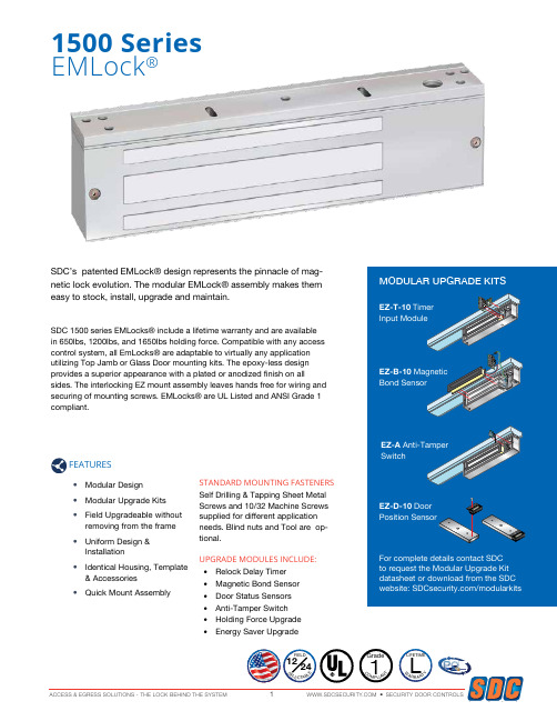
SDC’s patented EMLock® design represents the pinnacle of mag-netic lock evolution. The modular EMLock® assembly makes them easy to stock, install, upgrade and maintain.SDC 1500 series EMLocks® include a lifetime warranty and are available in 650lbs, 1200lbs, and 1650lbs holding force. Compatible with any access control system, all EmLocks® are adaptable to virtually any application utilizing Top Jamb or Glass Door mounting kits. The epoxy-less design provides a superior appearance with a plated or anodized finish on allsides. The interlocking EZ mount assembly leaves hands free for wiring and securing of mounting screws. EMLocks® are UL Listed and ANSI Grade 1 compliant.1500 SeriesEMLock®FEATURES• Modular Design • Modular Upgrade Kits • Field Upgradeable withoutremoving from the frame• Uniform Design &Installation• Identical Housing, Template& Accessories• Quick Mount AssemblySTANDARD MOUNTING FASTENERS Self Drilling & Tapping Sheet Metal Screws and 10/32 Machine Screws supplied for different application needs. Blind nuts and Tool are op-tional.UPGRADE MODULES INCLUDE:• Relock Delay Timer • Magnetic Bond Sensor • Door Status Sensors • Anti-Tamper SwitchSecurity Door ControlsSECURITY DOOR CONTROLS ACCESS & EGRESS SOLUTIONS - THE LOCK BEHIND THE SYSTEM21510 SERIES GRADE 11650 LB / 748 KG HOLDING FORCE1570 SERIES GRADE 11200 LB / 544 KG HOLDING FORCE 3 WATTS ENERGY SAVER1580 SERIES GRADE 1650 LB / 295 KG HOLDING FORCESPECIFICATIONSVoltage 12/24VDC Voltage Sensing InputSingle350mA @ 24VDC; 670mA @ 12VDC11” L x 2-3/4” H x 1-9/16” D Double700mA @ 24VDC; 1.34A @12VDC22” L x 2-3/4” H x 1-9/16” DSPECIFICATIONSVoltage 12/24VDC Voltage Sensing InputSingle125mA @ 24VDC; 250mA @ 12VDC11”L x 2-3/4”H x 1-9/16”DDouble 250mA @ 24VDC;500mA @ 12VDC22” L x 2-3/4” H x 1-9/16” DSPECIFICATIONSVoltage 12/24VDC Voltage Sensing InputSingle220mA @ 24VDC; 440mA @ 12VDC8-3/4”L x 2-1/8”H x 1-1/4”D Double440mA @ 24VDC; 880mA @ 12VDC17-1/2” L x 2-1/8” H x 1-1/4”D15821581151315121511UL Listed U.S. & Canada: GWXT Auxiliary LocksCVXJ Burglary Resistant Electrically Operate-Door LockUL10C: Position Positive Pressure CompliantUBC: Classified in accordance with Uniform Building Code standard 7-2 “Fire Test for Door Assemblies”ANSI/BHMA A156.23: Grade 1, one million cycles BHMA CertifiedCSFM: California State Fire Marshal Listed 3774-0324:100MEA: City of New York 61-95-E157315721571LISTINGS & PERFORMANCE SPECIFICATIONS1511 Single EMLock®1512 Double EMLock®1513 Single, split armature for pair of doors1571 Single EMLock®1572 Double EMLock®1573 Single, split armature for pair of doors1581 Single EMLock®1582 Double EMLock®MODELSFIELD INSTALLED OPTION KITS Ordered separately for field upgrade. For complete details contact SDC to request more information on Modular Upgrade Kits.EZ-T-10 Adjustable Timer InputModule: Specify (1) for single or double EmLocks®(not available with 1580 series) EZ-D-10 1510, 1570 Door Position Sensor Module: Specify (2) for double EMLocks®(not available with 1513 and 1573) EZ-D-80 1580 Door Position Sensor Module: Specify (2) for double EM-Locks®EZ-B-10 1510, 1570 Magnetic Bond Sensor Module: Specify (2) for double EMLocks®(Not available with 1513,1573) EZ-B-80 1580 Magnetic Bond Sensor Module: Specify (2) for double EM-Locks®EZ-A Anti-Tamper Switch Module: Indicates cover plate removal.EZ-1510W Holding Force Module: Ex-change a 1200lb wire coil (1570 series) with this 1650lb wire coil.Specify (2) for double EMLocks® EZ-1570W Energy Saver Module: Save on power supply and long term energy costs by exchanging 8.4 Watt, 1650lb coil with 3 Watt, 1200lb hold-ing force coil. Specify (2) for double EMLocks®All available throughACCESSORIESSpecify housings with your EMLocks ®. Example : 1511V-30; 1512V-60DC-2DC-1Anodized FinishesV Aluminum (standard) Y Black anodizedPainted FinishesC Brass powder coat X Dark bronze powder coat Plated Finishes (special order)P Bright chrome Q Dull chromeFEATURESVertical Housings - Side jamb mount, providing 2400 or 3300 lbs of holding force.FINISHACCESSORIESPRE-DRILLED & TAPPED HEADER BRACKETMachined Wire ChaseHoles Pre-Drilled & Countersunk For Frame MountingPre-Drilled and TappedLock Mounting HolesUF81VUF11VAluminum frames with blade stop - lowers EmLock below blade stop. Concrete filled hollow metal frames provides multiple points for concealed wire entry• Pre-drilled and tapped specifically for 1511, 1571, 1581 EmLock • Machined wire chase provides multiple points for concealed wireentry from concrete filled frames.• 628 Aluminum AnodizedFEATURESUsed in lieu of angle brackets, the Universal Header Bracket provides a faster mounting solution, saving time and labor costs for several EmLock models. Reduce potential for mis-sized and misaligned mounting holes, broken taps, removal of broken taps. Combined with interlocking. E-Z mount assembly, save up to a half days labor with the instal-lation of 12 locks.• Solid 1” bar provides higher security and superior aesthetics.• Machined wire chase provides concealed and secure wiring• Multiple pre-drilled and tapped mounting holes to accommodate theuse of several different locks on either 4” or 4.5” aluminum framesFEATURESFINISHV 628 Aluminum (standard)C 605 Bright BrassD 606 Dull BrassP 625 Bright Chrome Q 626 Dull Chrome X 313 Dark Bronze Y 335 BlackSecurity Door ControlsSECURITY DOOR CONTROLS ACCESS & EGRESS SOLUTIONS - THE LOCK BEHIND THE SYSTEM659mm51mm2"BA2 5/16"FILLER PLATESFor 22” (559mm) Double Emlock Models 1512 / 1572PART # A x BFP21 1/8” x 1-1/4” FP22 1/4” x 1-1/4” FP23 3/8” x 1-1/4” FP24 1/2” x 1-1/4” FP255/8” x 1-1/4”For 17-1/2” (445mm) Double Emlock Model 1582PART # A x BFP30 1/8” x 1-1/4” FP31 1/4” x 1-1/4” FP32 3/8” x 1-1/4” FP33 1/2” x 1-1/4” FP34 5/8” x 1-1/4”For 10”-11” Single Emlock & Exit CheckModels 1511, 1513, 1571, 15731511S, 1511T, 1511DEV, 1571DEV PART # A x B FP11 1/8” x 1-1/4” FP12 1/4” x 1-1/4” FP13 3/8” x 1-1/4” FP14 1/2” x 1-1/4” FP155/8” x 1-1/4”For 8-3/4” Single Emlock & Exit Check Models 1581, 1581DEPART # A x B FP01 1/8” x 1-1/4” FP02 1/4” x 1-1/4” FP03 3/8” x 1-1/4” FP04 1/2” x 1-1/4” FP05 5/8” x 1-1/4”2"2 5/16"59mm51mmGlass DoorTop RailGlassARMATURE MOUNTING PLATEAR11Y Armature mounting plate for 1511, 1571335 Black Anodized (Specify two for models 1512, 1572)AR11YD A rmature mounting plate with DPS for 1511, 1571.335 Black Anodized(Specify two for models 1512, 1572)The AR Mounting plate provides a solution for mounting the EMLock® armature to the top rail of herculite, aluminum and glass, wood and hollow metal doors that do not permit the use of thru bolts.APPLICATIONMODELSMODELSAPPLICATIONFor extension of the stop to provide a proper mounting surface on the underside of the header See Figure 1B.ANGLE BRACKETSREUSABLE HEAVY DUTYDRILL FIXTUREBLIND NUTPLACEMENT TOOLINTERLOCKING QUICK MOUNT ASSEMBLY1511-DF1581-DFadequate mounting surface. See Figure 1C.© 2018 SECURITY DOOR CONTROLS Security Door ControlsLIT-EMLOCK-BROCHURE 04/18[t] 800.413.8783 805.494.0622 [f] 866.215.3138 801 Avenida Acaso, Camarillo, CA 93012 PO Box 3670, Camarillo, CA 93011TYPICAL DOOR APPLICATIONS1511 1571 1581• AB Angle bracket • Aluminum frame• Aluminum & glass door • Push side mounting 1511-HDB1 1571-HDB11581-HDB1• Glass door mounting kit • AB series angle brackets • Metal or aluminum frame • Glass door w/o top rail • Push side mounting 1511-(36) 1571-(36)• Full width architecturalhousing• Specify length(30”, 36”, 40”, 48”)• Aluminum frame• Aluminum & glass door • Push side mounting 1511 1571 1581• Hollow metal frame • Wood/hollow metaldoor• Push side mounting1511-TJ1 1571-TJ11581-TJ81• Top jamb mounting kit • Hollow metal frame• Wood or hollow metal door • Pull side mounting 1512 1572 1582• AB Angle bracket • Aluminum frame• Aluminum & glass doors • Push side mounting1513 1573• Split armature• Hollow metal frame • Wood or hollowmetal doors• Push side mounting1512 1572 1582• Hollow metal frame • Wood or hollow metaldoors• Push side mounting1512-HDB2 1572-HDB21582-HDB2• HDB Glass door mountingkit• AB series angle bracket • Metal or aluminum frame • Glass door without top rail • Push side mountingCOMMUNICATING BATHROOM EMLOCKS®Single hospital bathroom shared by two patient rooms.SYSTEM OPERATIONBoth doors must be closed to lock.Activating CB401A (B) locks both doors.Activating CB401A (B) again unlocks both doors.When doors are locked, activating either CB401B (C) emergency release will unlock both doors.Both doors will unlock automatically via signal from fire panel.SYSTEM COMPONENTS (A)Fail Safe locks with door position switch. Example: 1511-DPS(B) CB401A System activation push switch.(C)CB401B Emergency release push switch to be mounted above each door. CB701B key switch optional.(D)631RF-UR1 Power Supply with Fire Panel Tie-In and Communicating Bath ControllerFROM FIRE PANEL 110 VAC INPUTPOWER SUPPYAABCC D。
派诺马达保护器定值整定

保护参数设置界面数码管显示内容表: 显示内容 启动超时保护 启动时间 执行方式 过载保护 K系数 执行方式 过流堵转 动作值 延动作值 延时时间 执行方式 短路保护 动作值 延时时间 执行方式 接地保护 动作值 延时时间 执行方式 漏电保护 动作值 延时时间 执行方式 欠载保护 动作值 延时时间 执行方式 外部故障 延时时间 执行方式 过压保护 动作值 延时时间 执行方式 欠压保护 动作值 延时时间 执行方式 TE时间 代号 Stover T Act Overid K Act Locked VL DT Act Phase DT Act UnbaI VL DT Act Short VL DT Act Earth VL DT Act Leakags VL DT Act UnderL VL DT Act ExternaL DT Act Overy VL DT Act Underv VL DT Act Te Act Locked VL DT Act Phase DT Act UnbaI VL DT Act Short VL DT Act Earth VL DT Act Leakags VL DT Act UnderL VL DT Act DT Act VL DT Act VL DT Act PTOSET 数码管显示 Stover T Act Overid 设置时间 设置范围 2-60s 报警(A) 跳闸(T) 10.16.24.40.60.80.1 00.130.180.280.400. 600.800.1000. 报警(A) 跳闸(T) 100-600%Ie 0.5-60.0s 报警(A) 跳闸(T) 0.02-5.00s 报警(A) 跳闸(T) 20-60% 0.5-5.0S 报警(A) 跳闸(T) 400%Ie-接触器允许分 断电流 0.10-5.00s 报警(A) 跳闸(T) 20-100%Ie 0.02-60.00s 报警(A) 跳闸(T) LE 20-100%Ie 0.02.60.00s 报警(A) 跳闸(T) 20-100%Ie 0.5-60.00s 报警(A) 跳闸(T) 1.0-60.0 报警(A) 跳闸(T) 105-150%Ue 0.5-60.00s 报警(A) 跳闸(T) 45-95%Ue 0.5-60.00s 报警(A) 跳闸(T) 打开(ON) 关闭(OFF) 实际整定设置
上海永日电梯资料
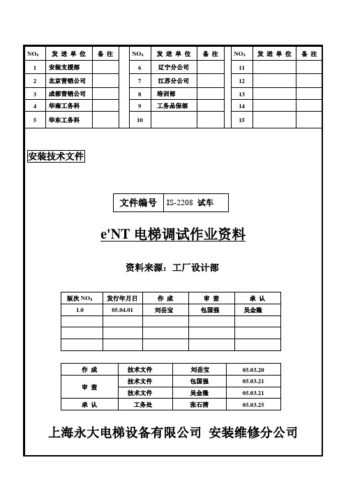
e’NT调试试运转及调整要领目录一、e’NT与NT差异对照表二、e’NT系统构成图三、e’NT的概要四、各PC板安装及工事配线确认五、各接地线连接取付实况六、R E及MOTOR配线CHECK七、作业上的注意事项八、电梯低速运转前的作业事项九、绝缘测定、PC板电压设定及调整十、低速试运转十一、高速运转前准备十二、高速运转准备十三、LINKLESS门机十四、阶高测定十五、高速确认十六、平衡电流测试十七、起动补偿调整十八、着床平层调整十九、电梯微速时间调整二十、MICRO运转水平调整二十一、乘场及车厢LED楼层显示器之点检二十二、各楼层开关门时间调整二十三、HALL LAN系统二十四、ANN操作二十五、特殊功能检查及设定二十六、车厢内照明及风扇的自动休止设定二十七、定位按钮功能二十八、PCB作业注意事项二十九、电梯命名规则三十、最终故障发生时间三十一、TCD码目录解说三十二、具体TCD码三十三、PCB连接器与端子说明.......................................1~4 (5).......................................6~8 .......................................9~18 .......................................19~21 .......................................22~23 (23).......................................24~25 .......................................25~26 (27) (28) (29).......................................30~34.......................................35~36 (36).......................................36~38.......................................38~40 (41) (42) (43) (43) (44).......................................45~51.......................................52~70.......................................70~74.......................................74~75 .......................................75~76.......................................77~79 (80) (81)…………………………………82~84…………………………………另附…………………………………85~101技术文件上海永大电梯设备有限公司版次第1.0版编号IS-2208 e’NT调试作业资料页次20 附图一、附图二、技术文件上海永大电梯设备有限公司版次第1.1版。
Samson定位器简介

当输入控制信号变化或有阀位偏差,则对气动执行机构加压 或泄压。若需要,可调整输出气量改善信号压力作用,还可 由软件设置输出信号压力限制值1.4、2.4、3.7巴。
装配到角行程气动执行机构(VDI/VDE 3845) 24 至 100O 开启角
在已初始化的行程/旋转角度:最大可调比为1:5
Байду номын сангаас总线连接
现场总线接口物理层 现场设备按照
IEC 61158-2,总线供电 113(没有防爆保护) 111(防爆保护型) FM3610实体,FISCO和FNICO
通信
现场总线
数据传输符合FOUNDATIONTM现场总线规范, 通信文件级别:31PS、32L; 互用性测试按互用性系统IST版本4.6
所需软件(本机)
SAMSON SSP接口和串行接口适配器 TROVIS-VIEW带3730-5数据库模块
允许工作电压
9 至 32 VDC · 通过总线供电 防爆型按EC检定证书中的限值。
最大工作电流
15mA
出错时的附加电流
0mA
气源
气源 空气质量
1.4 至 7 巴(20至105psi) 按ISO 8573-1(2001):最大颗粒尺寸和密度:4级 · 含油量:3级 露点:3级或必须低于预期的最低环境温度10K
– 集成的电磁阀 – 集成的增强版EXPERT+自诊断(T 8388 ZH) – 不锈钢外壳
相关产品信息表
T 8350 ZH
2008 年 8 月版
数据表
T 8384-5 ZH
AES 1235 安全门监控和应急停止安全控制模块 微处理器基于安全控制器(Series AES)
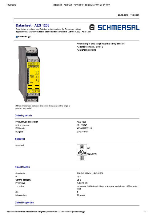
25.10.2016 11:34:08hDatasheet AES 1235Guard door monitors and Safety control modules for Emergency Stopapplications / Micro Processor based safety controllers (Series AES) / AES 123x Preferred typ(Minor differences between the printed image and the original product may exist!)• Monitoring of BNS range magnetic safety sensors • 2 safety contacts, STOP 0• 2 Signalling outputsOrdering detailsProduct type description AES 1235Article number 101170049EAN code 4030661297118eCl@ss 27371901ApprovalApprovalBG USA/CANClassificationStandards EN ISO 138491, IEC 61508PLup d Control category up 3PFH value 1.0 x 10⁷/h notice up to max. 50.000 switching cycles/year and at max. 80% contact load SIL 2Mission time 20 Y earsGlobal PropertiesProduct name AES 123xStandards IEC/EN 602041, IEC 6094753, EN 9541, BGGSET14, BGGSET20Compliance with the Directives (Y/N) Y esClimatic stress EN 6006823, BGGSET14Mounting snaps onto standard DIN rail to EN 60715Terminal designations IEC/EN 609471Materials Material of the housings Plastic, glassfibre reinforced thermoplastic, ventilated Material of the contacts AgNi, 0,2 µm gold flashedWeight160 gStart conditions Automatic or Start buttonStart input (Y/N)NoFeedback circuit (Y/N)Y esStartup test (Y/N)NoReset after disconnection of supply voltage (Y/N)Y esAutomatic reset function (Y/N)Y esReset with edge detection (Y/N)NoPullin delay ON delay with automatic start adjustable 0,1 / 1.0 sDropout delay Dropout delay in case of emergency stop< 50 msMechanical dataConnection type Screw connectionCable section Min. Cable section0,25 mm² Max. Cable section 2.5 mm²Prewired cable rigid or flexibleTightening torque for the terminals0,6 NmDetachable terminals (Y/N)NoMechanical life20.000.000 operationsElectrical lifetime150.000 operations for 230 VAC, 5 A (cos φ = 1)restistance to shock30 g / 11 msResistance to vibration To EN 600682610...55 Hz, Amplitude 0,35 mm, ± 15 %Ambient conditionsAmbient temperature Min. environmental temperature0°C Max. environmental temperature+55 °CStorage and transport temperature Min. Storage and transport temperature−25 °C Max. Storage and transport temperature+70 °CProtection class Protection classEnclosure IP40 Protection classTerminals IP20 Protection classClearance IP54Air clearances and creepage distances To IEC/EN 606641 Rated impulse withstand voltage U imp 4.8 kV Overvoltage category III To VDE 0110 Degree of pollution2 To VDE 0110Electromagnetic compatibility (EMC)EMC rating10 V/mElectrical dataRated DC voltage for controls Min. rated DC voltage for controls20.4 V Max. rated DC voltage for controls27.6 VRated AC voltage for controls, 50 Hz Min. rated AC voltage for controls, 50 Hz Max. rated AC voltage for controls, 50 HzRated AC voltage for controls, 60 Hz Min. rated AC voltage for controls, 60 Hz Max. rated AC voltage for controls, 60 HzContact resistance max. 100 mΩPower consumption< 5 WType of actuation DCSwitch frequency1 HzRated insulation voltage U i250 VRated operating voltage U e24 VDC ±15%Thermal test current I the6 AOperating current I e0,2 AElectronic protection (Y/N)NoInputsMonitored inputs Shortcircuit recognition (Y/N)optional Wire breakage detection (Y/N)Y es Earth connection detection (Y/N)Y esNumber of shutters adjustable 1 piece > 0 pieceNumber of openers adjustable 1 piece > 2 pieceInput resistance approx. 4000 Ω at GNDInput signal "1"10 ... 30 VDCInput signal "0"0 ... 2 VDCCable length1000 m with 0,75 mm² (for Rated voltage)OutputsStop category0Number of safety contacts2 pieceNumber of auxiliary contacts0 pieceNumber of signalling outputs2 pieceSwitching capacity Switching capacity of the safety contacts min. 10 mA, max. 6 A Switching capacity of the signaling/diagnostic outputs min. U e −4V / Y1, Y2: max. 100 mAFuse rating Protection of the safety contacts6 A gG Dfuse Fuse rating for the signaling/diagnostic outputs shortcircuit proof, ptypeSignalling output Y1: Authorized operation, safety contacts on;2 YNo authorised operation off:, safety contacts Utilisation category To EN 6094751AC15: 230 V /3 ADC13: 24 V / 2 ANumber of undelayed semiconductor outputs with signalingfunction2 pieceNumber of undelayed outputs with signaling function (withcontact)0 pieceNumber of delayed semiconductor outputs with signalingfunction.0 pieceNumber of delayed outputs with signalling function (with contact).0 pieceNumber of secure undelayed semiconductor outputs withsignaling function0 pieceNumber of secure, undelayed outputs with signaling function,with contact.0 pieceNumber of secure, delayed semiconductor outputs withsignaling function0 pieceNumber of secure, delayed outputs with signaling function (withcontact).0 pieceLED switching conditions displayLED switching conditions display (Y/N)Y esNumber of LED´s1 pieceIntegral system diagnosis ISDIntegral system diagnosis ISD The following faults are registered by the safety monitoring modules and indicated by ISD Failure of door contacts to open or close Crosswire or shortcircuit monitoring of the switch connections Interruption of the switch connections Failure of the safety relay to pullin or dropout Fault on the input circuits or the relay control circuits of the safety monitoring moduleMiscellaneous dataApplicationsSafety sensorGuard systemDimensionsDimensions Width22.5 mm Height100 mm Depth121 mmnoticeInductive loads (e.g. contactors, relays, etc.) are to be suppressed by means of a suitable circuit.notice Wiring exampleTo secure a guard door up to PL 3 and Category #03#Monitoring 1 guard door(s), each with a magnetic safety sensor of the BNS rangeThe feedback circuit monitors the position of the contactors K3 and K4.Start push button A start push button (NO) can optionally be connected into the feedback circuit. With the guard door closed, the enabling paths are then not closed until the start push button has been operated.If neither start button nor feedback circuit are connected, a jumper connection must be mounted between X1 and A1.If only one external relay or contactor is used to switch the load, the system can be classified in Control Category 3 to EN 9541, if exclusion of the fault “Failure of the external contactor” can be substantiated and is documented, e.g. by using a reliable downrated contactor. A second contactor leads to an increase in the level of security by redundant switching to switch the load off. Modification for 2 NC contacts:The safety monitoring module can be modified to monitor two NC contacts by bridging the terminals A1 and X2. The shortcircuit recognition between connections then becomes inoperative.Expansion of enable delay time:The enable delay time can be increased from 0,1 s to 1 s by changing the position of a jumper link connection under the cover of the unit.The wiring diagram is shown with guard doors closed and in deenergised condition.The ISD tables (Intergral System Diagnostics) for analysis of the fault indications and their causes are shown in the appendix.DocumentsOperating instructions and Declaration of conformity (de) 221 kB, 18.12.2012Code: mrl_aes_1235_1236_deOperating instructions and Declaration of conformity (it) 207 kB, 18.01.2013Code: mrl_aes_1235_1236_itOperating instructions and Declaration of conformity (jp) 314 kB, 18.01.2013Code: mrl_aes_1235_1236_jpOperating instructions and Declaration of conformity (en) 216 kB, 18.12.2012 Code: mrl_aes_1235_1236_enOperating instructions and Declaration of conformity (da) 211 kB, 18.01.2013 Code: mrl_aes_1235_1236_daOperating instructions and Declaration of conformity (fr) 208 kB, 18.01.2013 Code: mrl_aes_1235_1236_frOperating instructions and Declaration of conformity (es) 209 kB, 18.01.2013 Code: mrl_aes_1235_1236_esOperating instructions and Declaration of conformity (pl) 249 kB, 05.02.2015 Code: mrl_aes_1235_1236_plOperating instructions and Declaration of conformity (nl) 208 kB, 18.01.2013 Code: mrl_aes_1235_1236_nlOperating instructions and Declaration of conformity (br) 426 kB, 12.07.2010 Code: mrl_aes_1235_1236_brOperating instructions and Declaration of conformity (sv) 208 kB, 18.01.2013 Code: mrl_aes_1235_1236_svOperating instructions and Declaration of conformity (pt) 212 kB, 18.01.2013 Code: mrl_aes_1235_1236_ptOperating instructions and Declaration of conformity (cs) 254 kB, 18.01.2013 Code: mrl_aes_1235_1236_csWiring example (99) 20 kB, 22.08.2008Code: kaes1l41Wiring example (99) 20 kB, 22.08.2008Code: Maes1l11ISD tables (Intergral System Diagnostics) (de) 51 kB, 29.07.2008Code: i_ae2p01ISD tables (Intergral System Diagnostics) (en) 35 kB, 29.07.2008Code: i_ae2p02BGtest certificate (en) 134 kB, 03.11.2011Code: z_135p02BGtest certificate (de) 136 kB, 03.11.2011Code: z_135p01BGtest certificate (en) 265 kB, 15.04.2016Code: z_113p02BGtest certificate (de) 71 kB, 04.03.2016Code: z_113p01EAC certification (ru) 833 kB, 05.10.2015Code: q_6042p17_ruImagesProduct photoWiring exampleWiring exampleK.A. Schmersal GmbH & Co. KG, Möddinghofe 30, D42279 WuppertalThe data and values have been checked throroughly. Technical modifications and errors excepted. Generiert am 25.10.2016 11:34:09h Kasbase 3.2.5.F.64I。
DORIN压缩机电机保护模块精
OIL PRESSURE AND MOTOR PROTECTION MODULE 油压和电机保护模块SUMMARY/ 目录Introduction / 简介03 Technical characteristic and codes/ 技术特性和代码06 Electrical connection/电气接线09Introduction 简介All semi-hermetic compressors, from the model K1500CS to the model K7500CC, are fitted with the electronic module CPM.Officine Mario Dorin have developed a new model, called CPM3, which is perfectly interchangeable with previous model CPM2 seeBT005/99; new model is more reliable and its cabling is easier. It is interchangeable with relay INT69TM.The CPM3 provides a total protection of the compressor electrical part protection with termistor and the mechanical part protection against insufficient oil pressure. In order to obtain the two protections it is necessary to connect the CPM3 following the instructions given below for thermistor protection and also the differential pressure sensor DPS oil pressure protection which is optional . 从 K1500CS 到 K7500CC 的所有型号半封闭压缩机配置 CPM 电子模块;DORIN 公司开发了一种 CPM3的新型号,可与以前的 CPM2见 BT005/99 完全互换; 新型号更可靠,接线更容易;它与 INT69TM 继电器互换;CPM3为压缩机电气元件带热敏电阻器保护和机械元件油压不足保护提供完全保护; 为获得这 2种保护,有必要按以下说明连接 CPM3热敏电阻器保护和备选DPS 差动压力传感器油压保护Technical characteristics技术特性AdvantagesThe principal advantage, in comparison with traditional mechanical oil pressure switch, is that the capillary and the risk of leak is substituted by an electrical cable.Moreover there is the possibility to monitor the oil Pressure without having to connect pressure lines to the oil pump or the body of the Compressor.The Differential Pressure Sensor DPS is fitted directly on the oil pump and transmits a signal corresponding to the effective pressure value of the differential oil pressure to the electronic module via an electrical cable.All running parameters of CPM3 are already input at the factory and unchangeable. It is sufficient to put the DPS sensor on the body of the oil pump and connect it to the electronic module CPM3.The new CPM3 module is equipped with two terminals L that permit to be energized with 230V or 115V supply.Reset :By manually disconnecting the supply L–N to the module in case of insufficient oil pressure.Automatic in case of trip by termistors and anti short-cycle. 优点比较传统机械油压开关,其主要优点为毛细管和泄漏风险被电线取代;另外,可以监测油压而不用将压力管与油泵或压缩机机体连接;差动压力传感器DPS 直接装在油泵上,并通过电缆将差动油压的相应有效压力值信号传送到电子模块中;CPM3的所有工作参数均已在工厂输入, 是不可更改的;只要将 DPS 传感器装在油泵的泵体上并与 CPM3模块连接就足够了;新的 CPM3模块配置 2个接线端L 允许连接 230V 或 115V 电源;复位:在油压不足时,将电源火线 -零线L-N 与模块手动断开;遇到热敏电阻器触发和防止短路循环,自动断开;supply voltage standard option 电源电压标准备选 115 / 230 V ± 10% 24V ± 10% supply frequency电源频率50 / 60 Hzabsorbed power吸收功率3 VAcompressor contactor coil压缩机接触器线圈5 Amp. Ind.oil pressure alarm 油压报警 2 Amp. ind. maximum output power最大输出功率220 V - ACthermistors alarm热敏电阻器报警2 Amp. ind.electric terminals dimension for wire电线接线端尺寸mm thermistors set value热敏电阻器设定值kohm千欧姆temperature range温度范围-10 / + 60 °Crefrigerant compatibility制冷剂匹配性HCFC / HFCsetting differential oil pressure setting value standard 标准设定差动油压设定值option 备选 bar barlow oil pressure delay time seconds低油压延迟时间秒90delay after thermistors alarm热敏电阻器报警后延时5lubricating oil pressure switch润滑油压开关MANUAL 手动thermistors on electric motor电机热敏电阻器AUTOMATIC 自动part codes元件代号 Standard 标准 Optional 备选electronic module 电子模块 2CC1140115 / 2302CG2140 24Vpressure sensor 压力传感器 CPM3DPS 2CG4030bar2CG5030 barSetting values are made at the factory. They are unchangeable.We can propose as an option a sensor with an oil differential pressure setting at bar.This is for special installations.设定值为工厂设定,是不可更改的;我们可以提出一个选项,将传感器的油差动压力设定在巴; 用于特殊装置;Installation of the oil sensor DPS油差动压力开关传感器安装To install the sensor on the oil pump of the compressor follow the instructions below. Before acting on the compressor, it is necessary to:disconnect the electric motor from the mains supplyclose suction and discharge valves let make cold to room temperature depressurize compressor casing.按以下说明在压缩机油泵上安装传感器;在压缩机动作之前,有必要: 将电机与电源断开关闭吸气和排气阀让温度冷却到室温将压缩机壳体减压1 Unscrew the plug 1 and the copper gasket2 from the oil pump 5.4 Connect the sensor DPS with the electronic CPM as indicated below:Remove the existing bridge between terminal A-B of the module CPM.Connect the two wires of the DPS indifferently to terminals A-BRemarks 1: for cabling with CPM2 cod. 2CC1120 220V- 2CC2120 24V – 2CC3120 110VPrevious model of sensor DPS had three wires that were connected to terminals A-B-C; in case of substitution of the DPS with new model, connect the two wires of the DPS to terminals A-B leave C un-connected.Remarks 2: for cabling with previous sensor cod. 2CG1030 2CG3030 barDPS FITTED WITH CPM2 MUSTN’T BE USED WITH CPM3 1 从油泵5卸下旋塞1和铜垫2;2 用传感器提供的铜垫将4 DPS 传感器 3拧紧到位;3 用紧固扭矩35Nm ±10% 锁紧传感器;4 将 DPS 传感器与电子 CPM 模块按以下所示连接:拆下 CPM 模块接线端 A-B 之间的现有跨接线;将 DPS 两根线与接线端 A-B 任意连接;注 1:对 CPM2的接线代号 2CC1120 220V- 2CC2120 24V – 2CC3120 110VDPS 传感器的以前型号有三根线与接线 A-B-C 连接 ; 如果用新型号更换, 将DPS 的两根线与接线端 A-B 留下 C 不接连接;注 2:对以前传感器的接线代号 2CG1030 2CG3030 bar装配 CPM2的 DPS 不得与 CPM3使用;A Copper gasket 铜垫 G oil pressure alarm油压报警B oil pump油泵 H thermistors alarm热敏电阻器报警C remove this bridge when you connect thesensor DPS连接 DPS 传感器时拆下该跨接线ICommon 公共线D electric motor thermistor protection电机热敏电阻器保护Lconnected with LED alarm 与 LED 报警连接E compressor is stopped压缩机停机时开关 CC 或 C1关闭 Mon series with other protections 与其他保护装置串联F Run 运行 O Supply 电源Caution:Remove the link between the terminal A and B before sensor DPS installation.After the sensor DPS installation check that there are no leaks between the sensor and the pump.It is possible to check the correct running of the CPM/DPS.Switch off the connection cable between the sensor and the terminals A-B leaving the with live voltage.After 90 secs the electronic board must switch off the contact of the relay of the compressor and switch on the outlet of the oil pressure alarm.Remarks:The new electronic CPM3 has the same numbering as the Kriwan INT69TM module see above drawing. 注意:安装 DPS 传感器之前,拆下接线端 A 和 B 之间的连接;安装 DPS 传感器之后,检查传感器和泵之间无泄漏;可以检查 CPM /DPS的正确运行; 断开传感器和接线端 A-B 之间的连接线,让CPM 带电压; 90秒后,电路板须断开压缩机继电器的触点并接通油压报警的输出端;注:新电子模块 CPM3与 KriwanINT69TM 模块具有相同的编号见上图;PART WINDING UNLOADED START SE K5-K6-K7-Y6-Y7 系列分线圈卸载起动RO on / off contact接通 /断开触点C1contactor 1st winding 接触器线圈 1A0 oil pressure alarm油压报警C2contactor 2nd winding 接触器线圈 2PTC Thermistors热敏电阻器RCcrankcase heater 曲轴箱加热器T time delay relay for PWD sPWD秒延时继电器Atthermistors intervention alarm 热敏电阻器动作报警CPM3 protection module保护模块S1solenoid valve . for unloaded start 卸载启动常闭电磁阀DPS differential pressure sensor差动压力传感器PBlow pressure switch 低压开关Re1 DPS relayDPS 继电器PAhigh pressure switch 高压开关Re2 PTC relayPTC 继电器CContactor 接触器DIRECT STARTSE K5-K6-K7-Y6-Y7直接起动Re1 DPS RelayDPS 继电器Re2PTC relay PTC 继电器CPM3 protection module 保护模块RO ON/OFF contact 接通 /断开触点 At thermistors intervention alarm 热敏电阻器动作报警 RC crankcase heater 曲轴箱加热器 A0 oil pressure alarm 油压报警 PB low pressure switch 低压开关 PTC Thermistors 热敏电阻器 PA high pressure switch 高压开关CCContactor 接触器DPSdifferential pressure sensor 差动压力传感器STAR CONNECTION TYPE SE K5-K6-K7-Y6-Y7 Y型接线 DPS Relay PTC relay Re1 CPM3 At A0 PTC CC DPS继电器 protection module 保护模块 thermistors intervention alarm 热敏电阻器动作报警 oil pressure alarm 油压报警 Thermistors 热敏电阻器 Contactor 接触器 Re2 PTC继电器 ON/OFF contact 接通/断开触点 crankcase heater 曲轴箱加热器 low pressure switch 低压开关 high pressure switch 高压开关differential pressure sensor 差动压力传感器 RO RC PB PA DPSDELTA CONNECTION TYPE SE K5-K6-K7-Y6-Y7 △型接线 Re1 CPM3 At A0 PTC CC DPS Relay Re2 PTC relay PTC继电器 DPS继电器 protection module 保护模块 thermistors intervention alarm 热敏电阻器动作报警 oil pressure alarm 油压报警Thermistors 热敏电阻器 Contactor 接触器 RO RC PB PA DPS ON/OFF contact 接通/断开触点 crankcase heater 曲轴箱加热器 low pressure switch 低压开关 high pressure switch 高压开关 differential pressure sensor 差动压力传感器。
苏州新亚科技有限公司产品技术手册 V1.0 1 PLC3.0_SC02 螺杆压缩机控制模块 技术手册
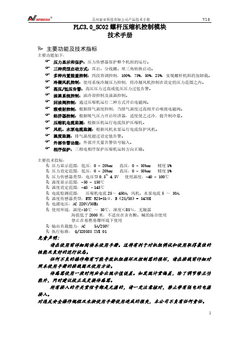
PLC3.0_SC02螺杆压缩机控制模块技术手册主要功能及技术指标主要功能如下:☞压力显示和保护:压力传感器保护整个机组的运行。
☞三种类型启动方式:直启、分线圈、星三角转换启动。
☞多种内置能量控制:四段容调控制,100%、75%、50%、25%,实现螺杆机组的加卸载。
☞冷凝风机控制:使用系统冷凝压力控制,将冷凝风机控制在设定的压力范围之内。
☞高压/低压告警:高压压力过高或低压压力过低告警。
☞油温系统控制:油冷却控制及油温控制。
☞回油阀控制:通过压缩机运行二种方式开启电磁阀。
☞液喷射控制:根据排气温度控制,当排气温度过高则开启喷液电磁阀。
☞经济器控制:根据吸气压力开启经济器,适度使之过冷,提升制冷量。
☞压缩机电流监测:根据压机运行电流保护压缩机。
☞风机、水泵电流监测:根据风机水泵运行电流保护风机。
☞温度监测:排气温度超过设定值告警。
☞外部告警功能:外部开关量告警信号输入。
☞相序保护:三相电相序保护压缩机运转方向正确。
主要技术指标:压力显示范围:低压:0 - 20bar 高压:0 - 50bar 精度1%压力设定范围:低压:0 - 20bar 高压:0 - 50bar 精度1%压力传感器类型:电压型0.5~ 4.5V 使用温度:-40 - 100℃温度显示范围:-50 - 150℃温度设定范围:-45 –145℃电流检测范围:压缩机电流25~ 450A;风机、水泵电流5 ~ 30A;温度传感器类型:NTC R25=5kΩ,B(25/50)= 3470K电源电压:AC 220V/50Hz使用环境:温度-10℃~ 50℃,湿度≤85%,无凝露海拔低于2000米,不适宜在含有酸、碱的场合使用禁止在易燃易爆环境下使用输出负载能力:AC 5A/250V执行标准: Q/320585 XYK 01免责声明:请在使用前详细阅读本使用手册。
这将有利于对机组调试和使用取得最佳的性能及良好的运行状态。
任何不良的操作都有可能导致机组损坏及控制器的损坏,请在接线前仔细对照本使用手册的接线图及使用方法。
西门子品牌的ASIsafe安全监控设备3RK1105-1BE04-2CA0的数据表说明书
Subject to change without notice © Copyright Siemens
104 81
Service&Support (Manuals, Certificates, Characteristics, FAQs,...) https:///cs/ww/en/ps/3RK1105-1BE04-2CA0
Reference code acc. to DIN 40719 extended according to IEC 204-2 acc. to IEC 750 Reference code acc. to DIN EN 61346-2
Ambient conditions Ambient temperature ● during operation ● during storage Protection class IP
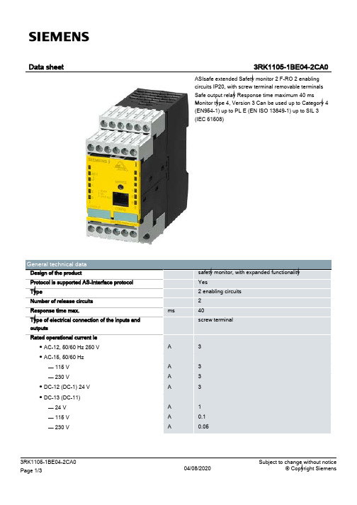
safety monitor, with expanded functionality
Yes
2 enabling circuits
2
ms
40
screw terminal
A
3
A
3
A
3
A
3
A
1
A
0.1
A
0.05
3RK1105-1BE04-2CA0 Page 1/3
04/08/2020
Subject to change without notice © Copyright Siemens
Data sheet
3RK1105-1BE04-2CA0
ASIsafe extended Safety monitor 2 F-RO 2 enabling circuits IP20, with screw terminal removable terminals Safe output relay Response time maximum 40 ms Monitor type 4, Version 3 Can be used up to Category 4 (EN954-1) up to PL E (EN ISO 13849-1) up to SIL 3 (IEC 61508)
DCM3A新版08
YVPT90-6
额定功率
180W
额定频率
0-50Hz
额定转矩
3.1N.m
绝缘等级
F
额定电压
220V
防护等级
IP20
速
880r/min
工作制式
S1
一、 导 言:本文目的说明如何正确使用、设置BLT DCM3A电梯门控制器(简称门控制器)。
二、电梯门控制器说明:
一导言二电梯门控制器说明1外型尺寸2操作面板3主电路接口及端子定义4双稳态开关信号接口及端子定义5门电机接口及端子定义6接地三基本运行方法1通则2利用操作面板监测双稳态开关和光电编码器四参数设置和变更的方法五参数详细说明六故障显示内容及其处置方法七异常情况及其对策八标准规格九其它电气部分说明1位置示意图2门电机3双稳态开关附录一sch模式下双稳态开关状态显示说明附录二常用操作简要说明1数码管位置功能描述熄灭点亮1ef开到达开关状态开关断开开关闭合1bc开变速开关状态开关断开开关闭合3ef关变速开关状态开关断开开关闭合3bc关到达开关状态开关断开开关闭合附录二常用操作简要说明
1、外型尺寸:300X124X87.5(长X宽X高)mm
蒂森控制板操作器说明
蒂森控制板操作器说明 Company Document number:WUUT-WUUY-WBBGB-BWYTT-1982GTD I A G N O S T I C U N I T IFunction 01 00 Display of error stackas per:显示故障堆栈 Example: Error ExplanationWeighting BW14 03AAjob-specific error messag 任务特性故障信息 N emergency stop 紧急停梯 XX landing 楼层 S stopping 停止YY undefined 未定义 M spontaneous message 自发信息 NN explanations from page 21 解释见21页 Blift blocked 电梯被锁定ZZ Number of marking flag 标志编号..B operation phase运行阶段Significance:Frequency levels of error:含义:故障频繁度Level 1 infrequent 1度不频繁发生Error code number 故障代码Level10Start/Stop buttonLK sensorRun: IS/RS 2)UP direction with IS DOWN direction with IS Program selector wheel LN sensorW/W1 contactor WO/WU S chützSeven-segment-function display flashing 1)PulsesCheck-back SR module Safety circuit EK HK TK KT1) can be suppressed with switch 6S1 on circuit board MZ or with switch S5 on circuit board MZ1.1) Dependenton the function involved, reset can either mean emergency stop following by adjusting run or stopping of the lift installation2) Handshake is defined as cyclical data exchange (telegram) between two data carriers.1) SR module can be masked out via teach-in mode function AF 0d. Running-open operation and re-levelling with door open is notpossible.1) Error from TCI work program 7 – no longer used.2) Error 35 00 and 3b 00 can no longer occur from work program 4 and error 36 00 can no longer occur from 25.1) SR module can be masked out through teach-in-mode function AF 0d. N Runnin-open operation and re-levelling with open door notpossible.2) 0C 04 to 0C 0C leads also to stopping, if not provided otherwise in the lift-specific EPROM !1) DSP is the digital signal processor in the CPI controller2) Handshake is defined as cyclical data exchange (telegram) between two data carriers.04 NN TCI control – Interrogation of ZSE solenoid switchesNN is represented as a hexadecimal number; in the event of errors, it indicates the number of ZSE switches (no other than the ZSE switch of the car position may be actuated).04 00 applies to ZSE 25 to ZSE 3104 00 applies to ZSE 17 to ZSE 2404 00 applies to ZSE 9 to ZSE 1604 0C applies to ZSE 1 to ZSE 8Example: 0 4 0 CHexadecimal number 0CBinary number 0 0 0 0 1 1 0 0assigned ZSE switch8 7 6 5 4 3 2 1The example shows that ZSE switches ZSE3 and ZSE4 (in 3. and 4. landing) have beenactivated. (Also compare hexadecimal code in part 4, page 2)04 NN TCM control – Interrogation of ZSE solenoid switchesIf ZSE switches are closed in the third and fourth landing, the TCM control will file two errors: 0403 und 04 0406 XX TCI control–Door locking not possible (from work program version 9)The lift will be put out of service for 15 min. after 3 unsuccessful door locking attempts. A newlocking attempt will be initiated after expiry of this period of time.XX = StandortDoor variant – hinged door:A new locking attempt will also be made within these 15 min. after opening of the landing door(TK open) and closingit again (TK closed).Door variant D4 (with mechanical locking device)A start attempt will be enabled within 15 min., as soon as the control receives the bolt contact.06 XX TCM control–Door locking not possibleIf open bolt contact is recognized in the command chain preceding the position the following errorwill follow14 XX (XX = bolt contact main side)18 XX (XX = bolt contact rear side)09 NN Car will be blocked in the landing >4 minExample 0 9 3 1LED Signal name (LED display on diagnostic unit I row A)0 KKD0 LSD1 KK .1 LS .0 TSUD0 TSOD0 TSU1 TSO activatedFor LEDs and signal names see Operating Instructions of Diagnostic Unit I, function 05 00,column 0d (display of predefined memory locations, from page 25).19 NN Door zone not detectedExample 1 9 C 81 VR1 A5A0 TO0 TU1 FL0 FS0 FO0 FUIn the operation phase STOP (lift at standstill), the CPU recognizes that the door zone calculatedfrom the landing vanes was left.For LEDs and signal names see Operating Instructions Diagnostic Unit I function 05 00, column05 (display of predefined memory locations,from page 25)1d NN Emergeny stop (wrong run direction)No run direction or both run directions were produced with the run contactor activated and thebrake disengaged.For LEDs and signal names see Operating Instructions, Diagnostic Unit I, function 05 00, column05 (display of predefined memory locations from page 25).In case of error 1d C8 the processor outputs the signals VR, A5A and FL (but without rundirections); compare above representation of error 19 NN1E NN Deceleration not effectiveBinary display of car positionIt will be examined whether deceleration has been initiated already on reaching the markedterminal landing vanes.The position is indicated by the five bitst 20 to 25 as binary number.Example: 1 E 9 d0 27FO (run direction UP)1 26FU activated (run direction DOWN)0 251 241 23Position (hexadecimal number converted into1 22binary number)0 211 201 E 9d: bits 20 to 27 stand for landing 29, therefore only run direction UP exists, since 26 = 0 and27 = 1, and consequently 9 d will follow.Function 02 00 Display of order number (fromTCI work program version 6 and with TCM)显示定单号码(从TCI 6版工作程序起以及TCM梯)Example: Order No.: 2770 06 42 105 12 3 10 1B A B A B Function 03 00 Position indicator (decimal) 楼层显示(十进制)Function 04 00 Operation phase1) Set function 05 00 with program selector wheel2) Press start-stop button3)Select desired column in 7-segment display with program selector wheelExample: Column 0d is desired. For example, select 0C 0d in 7-segment display, then left LED row B applies to column 0C and right LED row A applies to column 0d, etc.4) Interrogate LED display (compare overview and signal description)5) Exit: press start-stop button for longer than 2 s.The LEDs listed in the table will light on selecting the respective column (Col) :1) Error marking1) pulses are counted dependent on the run direction (20 to 27 is displayed in LED row A/B)1) will be displayed as hexadecimal number in LED row A. Example: 09 in LED row A LEDs 0000 1001 light up2)displays last failure before current failure cause column 2C. Is displayed in hexadecimal numbers as in column 2C1) MF3 (VA) stands for circuit board MF3 with double-sided insertion 1) MF3 (VA) stands for circuit board MF3 with double-sided insertion1) MF3 (VA) stands for circuit board MF3 with double-sided insertion1) not assigned currently.显示CPI。
微电脑控制器说明书
喷油螺杆空气压缩机微电脑控制器说明书上海康可尔压缩机有限公司SHANGHAI KANGKEER COMPRESSOR CO.LTD件号:119000-KE001 日期:2009-03-1螺杆压缩机控制器操作使用说明No. Contents Page142 3 5 技术参数2 保存/使用条件及说明3 注意事项 8 联网说明 8 1 2 3456 接线原理图 9 6 参数设置 47 英文说明 10 7 8英文版图表13811、技术参数1、开关量:8路光电隔离输入,5路继电器输出(最大7路);2、模拟量:1路4~20mA压力检测1路Pt100温度检测两组两路电流检测(含配套互感器两个);3、显示界面:最多同时显示48个16×16点汉字(4行,每行12个字)4、显示器控制器电源:AC18V 10VA 交流电源;总工作电流<150mA5、量程a)、电流测量范围:0~240A(更大电流检测需定制)。
分辨率0.1Ab)、温度测量范围:—20~120℃分辨率1℃c)、压力测量范围:0~1.60MPa 分辨率0.01MPad)、时间记录:0~999999小时分辨率1小时(按照小时记录)e)、输出继电器容量220V 5A(50万次寿命)6、相序保护:错相无法开机缺相保护时间小于1秒相不平衡保护时间16秒7、电机过载保护:电机电流大于额定电流的1.2倍时保护时间小于60秒;电机电流大于额定电流的1.3倍时保护时间小于48秒;电机电流大于额定电流的1.5倍时保护时间小于24秒;电机电流大于额定电流的1.6倍时保护时间小于8秒;电机电流大于额定电流的2.0倍时保护时间小于5秒;8、急停时间、超温、超压动作时间小于1秒。
9、温度校准精度≤0.5℃,压力传感器校准精度≤0.01MPa22、保存/使用条件1、保存环境:温度-20℃~+70℃干燥2、使用环境温度:-10℃~+60℃3、相对湿度:5%~95%,无结露4、其他要求:无腐蚀金属、破坏绝缘的气体存在,无显著的震动,无强磁场、电场。
螺杆式空压机MAM880控制器

螺杆空压机微电脑控制器MAM880用户手册深圳市普乐特电子有限公司地址:深圳市福田区商报路天健工业区25栋西六楼电话:(0755)83172098 83172822 邮编:518034传真:(0755)83172966 E-mail:*************网址:特点:●LCD中英文显示.●远程/机旁选择控制.●联动/独立选择运行.●对电机具有起停控制.●对空压机进行防逆转保护.●对温度进行检测与控制保护.●对电压进行检测与保护●RS-485通讯功能,支持MODBUS RTU协议。
●对电机具有缺相、过载、不平衡、电压过高、电压过低保护功能.●高度集成,高可靠性,高性价比.目录一、基本操作 (4)1、按键说明 (4)2、指示灯说明 (4)3、状态显示与操作 (5)4、运行参数、菜单 (5)3、用户参数查看及修改 (6)4、用户参数表及功能 (6)5、厂家参数查看及修改 (8)6、厂家参数表及功能 (9)7、调整参数 (10)8、操作权限及密码管理 (11)二、控制器功能及技术参数 (11)三、型号规格 (12)1、型号说明 (12)2、适用电机功率规格表 (12)四、安装 (13)1、机械安装 (13)2、电气安装接线 (14)五、控制过程 (15)1、单机运行 (15)2、联网控制 (16)3、风机运行 (16)六、预警与提示 (16)1、空滤器预警指示 (16)2、油滤器预警指示 (16)3、油分器预警指示 (17)4、润滑油预警指示 (17)5、润滑脂预警指示 (17)6、皮带使用时间到预警提示 (17)七、安全保护 (17)1、对电机的保护 (17)2、排气超温保护 (17)3、空压机防逆转保护 (17)4、供气压力超压保护 (17)5、传感器失灵保护 (17)八、常见故障的处理 (18)1、查看现场故障 (18)2、常见故障及原因 (18)九、联动控制、联网通信 (19)1、联动控制 (19)2、联网通信 (21)十、电气接线图 (22)一、基本操作1、按键说明图1.1.1——启动键:空压机处于待机状态时,按此键可启动空压机运行;联动控制功能正确设置时,如果空压机为1号机并设置为主机,按启动键启动空压机,同时启动联动控制功能。
- 1、下载文档前请自行甄别文档内容的完整性,平台不提供额外的编辑、内容补充、找答案等附加服务。
- 2、"仅部分预览"的文档,不可在线预览部分如存在完整性等问题,可反馈申请退款(可完整预览的文档不适用该条件!)。
- 3、如文档侵犯您的权益,请联系客服反馈,我们会尽快为您处理(人工客服工作时间:9:00-18:30)。
精品推介I Product Express
的省空间化做出贡献。
使用3线式,通过IO-Link主站连接支持IO-Link
的传感器和控制器,可实时发现异常位置和现象,缩短恢复时间。
可燃气体传感器预校准模块FSM-10Y-01是一种搭载了费加罗半导体式传感器TGS2610-D00的模块,具有耐久性好、稳定性高的特点。
此模块可提供与被检测浓度成比例的PWM输岀(模块中带有一存储器,岀厂前预标定数据存储其中),同时,模块还能够检测到传感器断线及短路故障。
模块操作温度范围广。
此外如检测甲烷、丙烷、氢气等,对有机气体的交叉灵敏度很低,对硅化合物的耐受性更佳,更适应恶劣环境。
丙烷气体预校准检测模块FSM-10Y-01的特点:与气体浓度成比例的PWM、USART数字输出;免维护;体积小;符合RoHS要求。
FSM-10Y-01丙烷气体预校准检测模块主要应用于检测可燃气体泄漏、可燃气体泄漏检测仪、工业用探测器等。
安全可编程控制器PNOZmulti2的使用通过软件配置十分简单易用。
用户现在还可以依靠新的扩展模块—
—PNOZ m EF8DI2DOT双极半导体输出模块来实现对机械压力机的安全监控。
模块提供两个安全双极输出用于控制压力机安全阀,或其他需要双极半导体信号切换的执行机构。
另外提供八个安全输入,它们 可以配置独立的滤波时间,所有相关的安全功能都可以被连接到该模块中,以便能够使用各种输入信号进行正确操作,比如急停、光栅、双手启动、凸轮监控传感器、断轴监控传感器和安全阀输出等。
配置PNOZ m EF8DI2DOT模块后,在软件工具PNOZmulti configurator(V10.7.0或以上)中可直接调用经过认证的压机功能块,例如用于压机操作模式或凸轮监控功能等,且全面的诊断选项帮助排故,从而 减少停机时间,非常简便经济。
一个特别的优势在于程序中会给该模块配置一个独立的模块程序(mIQ),其在模块上本地运行,循环时间短,仅为3ms,可以更快地控制输出切断从而获得更高的安全性。
除此之外,与上一代PNOZmulti classic系列相比,原压机功能集成在主模块PNOZ m2p之中,现在通过扩展模块使用更灵活,且组合主模块PNOZ m B0或m Bl后,整体解决方案体积相比原先减小50%,大大节省电柜空间。
产品特性:8个安全输入,可配置滤波参数:2个安全双极输岀,负载2A:2个测试脉冲输出,检测触点间短路;最大安全性可达PLe/SIL3;尺寸:101.4mm X22.5mm X120mm。
传感器世界2019.06 Vol.25NO.06Total
288。