Juniper JUNOS CLI 介绍
Juniper_JUNOS_CLI_介绍

输入以下命令,使用空格键将其补齐: sh<space>ow ro<space>ute sh<space>ow ch<space>assis h<space>ardware sh<space>ow conf<space>iguration cl<space>ear rip s<space>tastics res<space>tart ro<space>uting g<space>racefully
rollback只是将配置恢复到Candidat配置e
rollback 或者 rollback 0 恢复上次commit之前的配置
rollback 1 上两次commit之前的配置
总共可以恢复49份配置
rollback ? 可以显示每次commit的时间,确定恢复那份配置
run file show /config/juniper.conf.n.gz n为1-3,可以查看需要恢复配置的内容,对应于rollback 1-3 run file show /config/juniper.conf.gz对应rollback 0
run file show /var/db/config/juniper.conf.n.gz
n为4-49,可以查看需要恢复配置的内容,对应于rollback 4-
49
Copyright © 2009 Juniper Networks, Inc.
Juniper简单入门介绍-端口,静态路由,策略

Juniper简单入门介绍(配置端口,静态路由,配置防火墙策略)登陆Juniper设备后,需输入edit或者configuration 命令进入系统配置模式Juniper 系统自带命令和变量可按“空格”键补齐Juniper 系统“用户自定义”变量可按TAB键补齐一、配置端口Juniper配置端口是基于物理端口下的逻辑端口进行配置,例如set interfaces ge-0/0/5 unit 0 family inet address 192.168.1.1以上命令为ge-0/0/5口添加一个ip地址为192.168.1.1,其中unit为逻辑端口单元,范围0~16385,若再执行命令set interfaces ge-0/0/5 unit 1 family inet address 192.168.2.1则ge-0/0/5现在有两个ip分别为192.168.1.1和192.168.2.1以上命令也可以写成set interfaces ge-0/0/5.0 family inet address 192.168.1.1其中.0代表unit 0二、配置静态路由举例:现有网段125.39.91.240/28Juniper ge-0/0/0.0 设置ip为192.168.88.1set routing-options static route 0.0.0.0/0 next-hop 192.168.88.1其中0.0.0.0/0 表示任意目标地址,192.168.88.1为路由器直连网关。
再举例:让所有访问192.168.77.X的路由走192.168.99.1set routing-options static route 192.168.77.0/24 next-hop 192.168.99.1以上192.168.77段,掩码为24,而192.168.99.1为路由器直连网关。
三、配置zoneJunos基于zone开放防火墙策略,zone可以自己建立,建立之后再将需要的端口划到zone里。
Juniper+CLI基本配置(小结)

CLI配置:操作模式进入和退出操作模式:下面的例子显示了使用用户名root登陆到路由器进入到操作模式login: rootPassword:Last login: Wed Nov 28 18:40:03 from 192.168.161.250--- JUNOS 5.0R2.4 built 2001-09-25 02:34:13 UTCroot@52network>Exit the operational mode by using the quit command:root@52network> quit52network (ttyd0)login:设置CLI:1. set cli命令:root@52network> set CLI ?Possible completions:complete-on-space Toggle word completion on spaceidle-timeout Set the CLI maximum idle timeprompt Set the CLI command prompt stringrestart-on-upgrade Set CLI to prompt for restart after a software upgrade screen-length Set number of lines on screenscreen-width Set number of characters on a lineterminal Set terminal type2.set CLI complete-on-space这个命令将允许自动完成命令,语法如下:set CLI complete-on-space <on|off>例子:root@52network> show p^'p' is ambiguous.Possible completions:pfe Show packet forwarding engine datapim Show information about PIMpolicy Show policy informationroot@52network> show po<space>root@52network> show policy3.set CLI idle-timeout设置CLI会话空闲时的最大时间语法:set CLI idle-timeout <timeout> (0-100000 minutes)例子:root@52network> set CLI idle-timeout 1Idle timeout set to 1 minuteroot@52network> Warning: session will be closed in 10 seconds if there is no activityIdle timeout exceeded: closing session4.set CLI prompt设置cli会话操作模式下的提示符语法:set cli prompt <cli-prompt>例子:root@52network>set cli prompt newpromptnewprompt>5.set CLI restart-on-upgrade设置当软件更新完成,将提示去重新启动路由器,默认打开语法:set CLI restart-on-upgrade <on|off>6.set CLI screen-length and screen-width设置cli屏幕长度和宽度语法:set CLI screen-length <length> Number of lines on screen (0..100000) set CLI screen-width <width> Number of characters on a line (0..100000) 例子:root@52network> set CLI screen-length 2Screen length set to 2root@52network> set CLI screen-width 5Screen width set to 57. set CLI terminal设置路由器的终端类型root@52network> set CLI terminal ?Possible completions:ansi ANSI-compatible terminalsmall-xterm Small (24 line) xterm windowvt100 VT100-compatible terminalxterm Large (65 line) xterm window7. set date设置时间语法:set date <time> New date and time (YYYYMMDDhhmm.ss)例子:root@52network> set date 200202171448.00Sun Feb 17 14:48:00 UTC 20028. 操作模式中的基本操作:Function Keyboard SequenceMove cursor back one character Ctrl-bMove cursor forward one character Ctrl-fMove cursor to beginning of line Ctrl-aMove cursor to end of line Ctrl-eDelete character before the cursor Ctrl-h, Delete, Backspace Delete character the cursor is on Ctrl-dDelete word before cursor Ctrl-w, Esc-Backspace, Alt-Backspace Insert most recently deleted text at the cursor Ctrl-yRedraw the current line Ctrl-lScroll backward through history Ctrl-pScroll forward through history Ctrl-nSearch CLI history in reverse order Ctrl-rMove cursor back one word Esc-b or Alt-bMove cursor forward one word Esc-f or Alt-fDelete the word after the cursor Esc-d, Alt-dSearch CLI history Esc-/Specify the number of times to execute a key-board sequence (number from one to nine)Esc-number sequence, Alt-number sequence9. cli注释信息:root@52network> show con^'con' is ambiguous.(命令不完整)root@52network> set CLI^syntax error, expecting <command>(语法错误)10.控制cli输出信息:1.显示输出:root@52network> show configurationversion 5.0R3.3;system {host-name 52network;login {user test {uid 2001;class superuser;authentication {encrypted-password "$Upc0"; # SECRET-DATA}}user root {uid 2000;class superuser;authentication {encrypted-password "0"; # SECRET-DATA---(more)---定制输出信息使用管道参数:这个参数可以帮助在一个大的文件中快速的找到制定的信息root@52network> show configuration | ?Possible completions:count Count occurrencesdisplay Display additional informationexcept Show only text that does not match a patternfind Search for the first occurrence of a patternhold Hold text without exiting the --More-- prompt match Show only text that matches a patternno-more Don't paginate outputresolve Resolve IP addressessave Save output text to a filetrim Trim specified number of columns from start of line 2.过滤输出信息1. count:显示文件或列表行数语法:show route protocol isis | count例子:root@52network> show configuration | countCount: 143 linesroot@52network> show route protocol isis | countCount: 59 lines2.display:display命令提供显示输出xml格式语法:show configuration | display xml例子:root@52network> show configuration | display xml | find interfaces <interfaces><interface><name junos:key="key">fxp0</name><speed>100m</speed><link-mode>full-duplex</link-mode><unit><name junos:key="key">0</name><encapsulation>802.3-llc</encapsulation><family><inet><address><name junos:key="key">192.168.161.16/24</name></address></inet></family></unit></interface></interfaces></configuration></rpc-reply>3.except:此参数设置显示输出信息不包含指定信息语法:show configuration | except <pattern> pattern to avoid例子:root@52network> show configurationversion 5.0R3.3;system {host-name 52network;login {user test {uid 2001;class superuser;authentication {encrypted-password "$1$A"; # SECRET-DATA }}user root {uid 2000;class superuser;authentication {encrypted-password "niG0"; # SECRET-DATAroot@52network> show configuration | except uidversion 5.0R3.3;system {host-name 52network;login {user test {class superuser;authentication {encrypted-password "$1$A"; # SECRET-DATA}}user root {class superuser;authentication {encrypted-password "niG0"; # SECRET-DATA4.find 和match命令find查找指定信息,并且显示所有相似信息match查找指定信息,并且只显示此指定信息语法:show route | find <pattern> pattern to search forshow route | match <pattern> pattern to match against例子:root@52network> show route | find 192.168.161.0192.168.161.0/24 *[Direct/0] 3d 02:05:58> via fxp0.0192.168.161.16/32 *[Local/0] 3d 02:05:58Localroot@52network> show route | match 192.168.161.0192.168.161.0/24 *[Direct/0] 3d 02:06:085.holdhold参数设置通过up和down翻动查看文件。
juniper交换机基本操作手册

juniper交换机操作手册信息中心网络产品开发部一、Juniper管理界面说明: (4)二、典型配置 (4)2.1系统配置模式典型配置 (4)2.1.1 configure (4)2.1.2 Monitor (4)2.1.3 Ping (4)2.1.4 telnet (5)2.1.5 Traceroute (5)2.1.6 Restart (5)2.1.7 Request (5)2.1.7.1 系统重启 (5)2.1.7.2 保存救援配置 (5)2.1.7.3 系统软件升级: (5)2.1.8 Show (6)2.1.8.1查看系统硬件信息: (6)2.1.8.1.1查看系统硬件警告: (6)2.1.8.1.2查看系统硬件环境信息 (6)2.1.8.1.3查看板卡cpu和内存情况 (7)2.1.8.1.4查看交换机硬件的注册及型号 (7)2.1.8.1.5查看插槽具体信息 (7)2.1.8.1.6查看路由引擎的CPU/内存/启动时间等信息: (7)2.1.8.2查看当前系统配置 (8)2.1.8.3 查看poe口的供电情况: (9)2.1.8.4 查看系统信息: (9)2.1.8.4.1查看系统备份配置 (10)2.1.8.4.2 查看系统保存操作的基本信息 (10)2.1.8.4.3 查看系统当前时间及启动时间 (10)2.1.8.4.4查看系统传输层连接情况 (10)2.1.8.4.5查看系统进程占用资源情况 (11)2.1.8.4.6查看系统各类软件版本情况 (11)2.2管理配置模式典型配置 (12)2.2.1配置模式介绍 (12)2.2.1.1使用set命令 (12)2.2.1.2使用edit命令 (13)2.2.2 相关注意事项 (13)2.2.3配置二层端口 (14)2.2.4 配置三层端口 (14)2.2.5配置基本接口参数: (15)2.2.6 vlan的相关配置 (15)2.2.6.1配置vlan (15)2.2.6.2 将vlan部署到接口上 (15)2.2.6.3配置三层vlan端口 (16)2.2.6.4将三层vlan接口与vlan匹配 (16)2.2.7三层协议配置 (16)2.2.7.1静态路由相关配置 (16)2.2.7.2 OSPF协议相关配置 (16)2.2.7.2.1 区域配置 (16)2.2.7.2.2 配置末节及nssa区域 (17)2.2.7.2.3 ospf类型配置 (17)2.2.7.2.4 ospf邻居参数配置 (17)2.2.8 链路聚合配置 (17)2.2.8.1 配置链路聚合参数 (17)2.2.8.2 配置接口进入链路聚合接口 (18)2.2.8.3 配置聚合接口参数 (18)2.2.9 日常保障配置 (19)2.2.9.1 密码恢复 (19)2.2.9.2 恢复出厂设置 (19)一、Juniper管理界面说明:Juniper交换机一共有两种管理界面:传统CLI界面与J-web界面。
juniper交换机基本操作手册

j u n i p e r交换机基本操作手册work Information Technology Company.2020YEARjuniper交换机操作手册信息中心网络产品开发部一、Juniper管理界面说明: (5)二、典型配置 (5)2.1系统配置模式典型配置 (5)2.1.1 configure (5)2.1.2 Monitor (5)2.1.3 Ping (6)2.1.4 telnet (6)2.1.5 Traceroute (6)2.1.6 Restart (6)2.1.7 Request (6)2.1.7.1 系统重启 (6)2.1.7.2 保存救援配置 (6)2.1.7.3 系统软件升级: (6)2.1.8 Show (7)2.1.8.1查看系统硬件信息: (7)2.1.8.1.1查看系统硬件警告: (7)2.1.8.1.2查看系统硬件环境信息 (7)2.1.8.1.3查看板卡cpu和内存情况 (8)2.1.8.1.4查看交换机硬件的注册及型号 (8)2.1.8.1.5查看插槽具体信息 (8)2.1.8.1.6查看路由引擎的CPU/内存/启动时间等信息: (8)2.1.8.2查看当前系统配置 (9)2.1.8.3 查看poe口的供电情况: (10)2.1.8.4 查看系统信息: (10)2.1.8.4.1查看系统备份配置 (11)2.1.8.4.2 查看系统保存操作的基本信息 (11)2.1.8.4.3 查看系统当前时间及启动时间 (11)2.1.8.4.4查看系统传输层连接情况 (11)2.1.8.4.5查看系统进程占用资源情况 (12)2.1.8.4.6查看系统各类软件版本情况 (12)2.2管理配置模式典型配置 (13)2.2.1配置模式介绍 (13)2.2.1.1使用set命令 (13)2.2.1.2使用edit命令 (14)2.2.2 相关注意事项 (14)2.2.3配置二层端口 (15)2.2.4 配置三层端口 (15)2.2.5配置基本接口参数: (16)2.2.6 vlan的相关配置 (16)2.2.6.1配置vlan (16)2.2.6.2 将vlan部署到接口上 (16)2.2.6.3配置三层vlan端口 (17)2.2.6.4将三层vlan接口与vlan匹配 (17)2.2.7三层协议配置 (17)2.2.7.1静态路由相关配置 (17)2.2.7.2 OSPF协议相关配置 (18)2.2.7.2.1 区域配置 (18)2.2.7.2.2 配置末节及nssa区域 (18)2.2.7.2.3 ospf类型配置 (18)2.2.7.2.4 ospf邻居参数配置 (18)2.2.8 链路聚合配置 (18)2.2.8.1 配置链路聚合参数 (19)2.2.8.2 配置接口进入链路聚合接口 (19)2.2.8.3 配置聚合接口参数 (19)2.2.9 日常保障配置 (20)2.2.9.1 密码恢复 (20)2.2.9.2 恢复出厂设置 (20)一、Juniper管理界面说明:Juniper交换机一共有两种管理界面:传统CLI界面与J-web界面。
juniper路由器入门资料

自己总结的一点juniper 路由器入门资料juniperbbs 2007-09-1922:41:55由于文档全是鸟语的,再加上哥们鸟语水平非常有限,所以可能在理解上有所偏差,大家将就着看吧!感谢大猫猫,红头发等前辈!访问路由器你可以通过三种管理接口访问路由器console(Db9 EIA-232 @ 9600 Bps, 8/N/1-pre-configured)、auxiliary 、f xp 0Telnet 、SSH 也可访问路由器你必须掌握需要访问路由器的密码当你第一次访问路由器时,你必须使用root 帐号登陆访问CLI(用户命令行),然后为路由器配置一个新的帐号用户登录访问必须用户名和密码个人帐户和路由器地址帐户可控制路由器的级别必须要有管理员授权当你通过用户帐号及密码登录路由器后,你就可以顺利的进入控制平台,可以在用户名和路由器名前看到“>”提示符Juniper需要通过用户名和密码来访问,路由器管理员可以创建用户帐号和分配权限,新的Juniper路由器只有没有密码的root帐号访问,你必须使用cli命令从CLI开始配置CLI模块及其重要内容CLI操作方式编辑命令行执行命令和命令历史相关内容和帮助Unix风格的管理模式CLI的配置方式不同的操控级别不同的配置权限同级别命令集之间的跳跃配置命令的自动检错系统自动回滚功能输入多命令行的可以一次执行在配置状态中执行操作命令保存、载入、删除配置文件CLI的两种模式操作模式(opera tional mode)显示路由器当前状态、监视、检测JUNOS、网络连通性及路由器硬件可以使用monitor、ping、show、test、tr acer oute命令展示JUNOS在执行时的信息和统计信息、路由表、可以测试网络的连通性Doug@lab2>配置模式(configuration mode)配置路由器、包括接口、普通路由信息、路由协议、用户访问、系统硬件相关[edit]Doug@lab2#CLI命令层次CLI操作模式命令(user@host>状态下配置)showrequestrestartpingtracerouteclearmonitorfiletesttelnetsetsshstartquit命令类型破坏性的非破坏性的进入配置模式控制CLI环境跳出CLI监视和检错命令clear monitor ping show test traceroute连接其他的网络系统复制文件重启软件程序使用过滤/管道命令输出compare(filename|rollback n):在这里可用的配置模式只能使用show命令,可以与所选择的配置文件进行比较count:显示输出线路数量display detail:只能在配置模式里使用,显示配置内容的其他信息except regular-express ion:当搜索输出时忽视正确的表达式文本,当正确的表达式包含空间、操作、通配符信息,你必须把它封装find regular-expression: 显示首先发现的输入文本holdmatchno-moreresolvesave控制CLI环境使用set cli 命令可以配置:Screen length(lines)Screen width(columns)Idle timeout(minutes)空闲时间Pro mpt(string)提示信息Terminal(terminal type)user@host> set cli ?Possible completions:complete-on-space Toggle word completion on spaceidle-timeout Set the cli maximum idletimeprompt Set the cli command promptstringrestart-on-upgrade Set cli to prompt forrestart after asoftware upgradescreen-length Set number of lines onscreenscreen-width Set number of characters onterminal Set terminal type可编辑命令行快捷键命令配置模式进入配置:使用configure命令进入配置模式在配置水平层面之间转换:使用edit、up、top、exit命令实现显示候选配置:在配置模式里使用show命令批量配置:执行候选配置:使用commit命令执行配置配置接口命名永久接口配置接口(物理道具和逻辑道具)使用configure命令进入配置模式root@lab2> configureEntering configuration mode[edit]root@lab2#容许单一的用户进行配置和编辑,configure exclusive Configure private 容许多用户编辑候选配置多用户可以同时编辑私有的候选配置信息在执行命令时,用户的个人选择是可以在全部信息中返回的????选择可执行的命令user@host# set alarm sonet lol reduser@host# delete alarm sonet pll yellow显示候选和可执行命令的不同[edit chassis]user@host# show | comparealarm {sonet {+ lol redlos red;- pll yellow;}}其他命令选项user@host# show | compare filenameuser@host# show | compare rollback number配置群声明的群能应用不同部分的配置应用相同参数的捷径方式可以配置更多的端口共同的群声明可以重复配置不同的地方想要配置的地方可以从原配置数据继承相关信息[edit]lab@San Jose-re0# show groups re0 re0 {system {host-name SanJose-re0;}interfaces {fxp0 {unit 0 {family inet {a ddr ess 192.168.200.51/24;}}}}}[edit]lab@SanJose-re0# show groups re1 re1 {system {host-name SanJose-re1;}fxp0 {unit 0 {family inet {address 192.168.200.52/24;}}}}}[edit]lab@SanJose-re0# showap ply-groups [ re0 re1 ];执行配置命令按你的需求使配置改变可能会破坏路由器的连通性可能会破坏网络的连通使用commit命令的缺点慢执行配置可能花费一点时间,默认10分钟假如配置是由缺陷的,路由器自动返回原来的配置可以使用rollback命令来恢复九种以保存的配置使用rollback(rollback 0)去恢复候选配置Rollback 1 载入意见的配置Rollback n[edit]user@host# rollbackload completeTo activate the configuration that you loaded, issue the commit command,as shown below.[edit]user@host# commit[edit]user@host# rollback versionload complete[edit]user@host#退出配置模式使用exit命令返回顶层使用exit configuration-mode返回其他层保存配置文件来自当前水平层面和向下的所有当前候选配置文件可以使用save命令以ASC II码的形式保存[edit]cli# save filename[edit]cli#必须指定详细的目录文件可以URL多余的路由引擎SSH user@host:filename载入配置文件Load命令不考虑现有配置Load override filename合并新的声明到现有配置Load merge filename取代现有声明在当前配置Load replace filename只选择候选配置你必须使用commit命令来执行能从终端载入Load(replace|merge|override)terminal端口配置端口contained包含PICPIC plugs堵塞FPCFPC有四个PIC插槽FPC flexible pic concentrator把交换控制板和路由器接口进行连接For example, so-1/2/3 is a SONET/SD H interface in FPC slot 1, PIC slot 2, and PIC port 3. _ at—ATM over SONET/SDH ports_ e1—E1 ports_ e3—E3 ports_ fe—Fast Ethernet ports_ so—SONET/SDH ports_ t1—T1 ports_ t3—DS-3 ports_ ge—Gigabit Ethernet ports_ ae—Aggregated合计Ethernet portslogi ca l合理的端口是设置帧中继和ATM虚拟circuit电路端口号是separate分离actual实际的DLCI ATM VC 和能获取任意值Suggest 暗示converntion协定是保持他们相同可能路由器有两个永久接口Fxp0对外管理接口管理对外以太网接口Fxp1用于信息包发送的引擎内在路由引擎连接管理对内以太网接口Juniper 的命令行接口简介:(详见文档:/techpubs/software/junos/junos60/index.html)Juniper 路由器的操作系统JOS建立在FreeBSD之上,使用超级终端连接到路由器前面板的Console口上之后,看到的是UNIX的登录提示:Login:使用用户名root,密码为空登录系统,出现提示:root#使用命令cli启动JOS的命令行接口(Command Line Interface):root#cliroot@Hostname>此时的状态为Operation Mode(操作模式),可以使用show、monitor等命令检查系统各项功能的运行状态。
Juniper-MX路由器restart chassis-control-不同的CLI命令行为

Junos OS提供了不同的关键字来重启chassis-control 依赖于不同的要求,这个KB主要是提供每个命令的使用情况。
使用命令:restart chassis-control不同,依赖于是否开启了GRES。
当GRES启用时,不同的Knobs时有不同的行为:1. restart chassis-control: SIGTERM存在的chassis-control进程将会停止,新的一个进程ID将会开始SIGTERM(终止进程)很流程化的去Kill掉这个进程,这个进程抓住了这个信号之后,识别到想要它Shut down,关闭它可能想要打开的任何日志文件,在Shutting down之前,通常在关机之前完成它正在做的事情。
某些情况下,进程可能会忽略SIGTERM,如果它正在处理一些不能被打断的任务PFE( fpc/feb/cfeb/dpc/mpc/)将不会被重启。
m20-a-re0> restart chassis-controlChassis control process started pid 576692. restart chassis-control gracefully:SIGTEM存在的chassis-control进程将会停止,新的进程将会开始,SIGTERM会优雅的去Kill掉这个进程,这个进程将会抓取到这个信号,识别到自己将将要shut down,关闭它可能想要打开的任何日志文件,在Shutting down之前,通常在关机之前完成它正在做的事情。
某些情况下,进程可能会忽略SIGTERM,如果它正在处理一些不能被打断的任务PFE( fpc/feb/cfeb/dpc/mpc/)将不会被重启。
m20-a-re0> restart chassis-control gracefullyChassis control process started pid 581173. restart chassis-control immediately:SIGKILL (无条件终止)存在的chassis-control进程将会停止,启用新的一个进程,SIGKILL(无条件终止)不能被进程忽略掉。
Juniper路由产品简介

JUNOS Internet软件 RE
转发表
更新
Internet
处理器 II
PFE
转发表
交换结构
I/O 卡
I/O 卡
Juniper路由产品简介
ASIC实现IP高性能转发服务
控制与转发分离的架构, 服务与性能兼得
使用特定ASIC开启多种业务, 同时保持性能的报文过 滤, DDoS识别,限速, CAR, QoS, Differserv, DS-TE
600 300 200Biblioteka J2320J2350
J4350
J6350
小型办公室
中小型分支
中型企业
Juniper路由产品简介
M系列高性能企业路由器
▪ 运营商级的高可靠性满足企业网络高性能的需求 ▪ 依靠IP/MPLS, IPv6, QoS, multicast 以及 VPN 等高级技术,为网络提供服务 ▪ 提供灵活的服务: NAT, stateful firewall, J-Flow accounting, IPSec, Tunnel, cRTP ▪ JUNOS软件确保有效而准确的技术部署
2007 T1600
超过150个用户网络部署了2500台 T-series 路由器
投资保护 ------7-10 年的生命周期
持续的扩展性 持续的扩展能力
Juniper路由产品简介
Juniper M/MX-Series 产品-大中型园区网的选择
Gbps 960
480
所有M系列路由器使用统一的JUNOS系统
1st 40G platform (8) Ports in ½ rack
Optimal Scale 3rd Dimension
Juniper_SRX配置手册
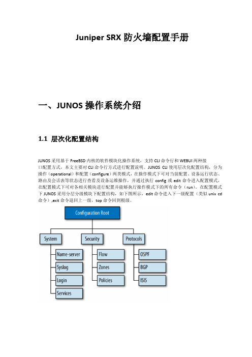
Juniper SRX防火墙配置手册一、JUNOS操作系统介绍1.1 层次化配置结构JUNOS采用基于FreeBSD内核的软件模块化操作系统,支持CLI命令行和WEBUI两种接口配置方式,本文主要对CLI命令行方式进行配置说明。
JUNOS CLI使用层次化配置结构,分为操作(operational)和配置(configure)两类模式,在操作模式下可对当前配置、设备运行状态、路由及会话表等状态进行查看及设备运维操作,并通过执行config或edit命令进入配置模式,在配置模式下可对各相关模块进行配置并能够执行操作模式下的所有命令(run)。
在配置模式下JUNOS采用分层分级模块下配置结构,如下图所示,edit命令进入下一级配置(类似unix cd 命令),exit命令退回上一级,top命令回到根级。
1.2 JunOS配置管理JUNOS通过set语句进行配置,配置输入后并不会立即生效,而是作为候选配置(Candidate Config)等待管理员提交确认,管理员通过输入commit命令来提交配置,配置内容在通过SRX 语法检查后才会生效,一旦commit通过后当前配置即成为有效配置(Active config)。
另外,JUNOS 允许执行commit命令时要求管理员对提交的配置进行两次确认,如执行commit confirmed 2命令要求管理员必须在输入此命令后2分钟内再次输入commit以确认提交,否则2分钟后配置将自动回退,这样可以避免远程配置变更时管理员失去对SRX的远程连接风险。
在执行commit命令前可通过配置模式下show命令查看当前候选配置(Candidate Config),在执行commit后配置模式下可通过run show config命令查看当前有效配置(Active config)。
此外可通过执行show | compare比对候选配置和有效配置的差异。
SRX上由于配备大容量硬盘存储器,缺省按先后commit顺序自动保存50份有效配置,并可通过执行rolback和commit命令返回到以前配置(如rollback 0/commit可返回到前一commit配置);也可以直接通过执行save configname.conf手动保存当前配置,并执行load override configname.conf / commit调用前期手动保存的配置。
juniper基本概念

juniper基本概念Juniper是一家提供各种网络产品和解决方案的技术公司,其产品主要用于构建和管理企业级网络和云服务。
以下是一些Juniper的基本概念:1. 路由器和交换机:Juniper生产高性能的路由器和交换机,用于连接和转发数据包在网络中的不同设备和地点之间。
2. Junos操作系统:Junos是Juniper开发的操作系统,用于驱动其路由器和交换机。
Junos以其高度可靠和可扩展的特性而闻名,具有丰富的网络功能和管理工具。
3. SRX防火墙:SRX系列是Juniper的安全设备,用于提供高级网络安全功能,包括防火墙、入侵检测和防御、虚拟专用网络(VPN)和流量分析等。
4. Contrail:Contrail是Juniper的软件定义网络(SDN)解决方案,提供网络虚拟化和自动化的功能。
Contrail可以帮助企业构建可扩展和灵活的网络基础设施,简化网络部署和管理。
5. MX系列路由器:MX系列是Juniper的高性能路由器,专注于服务提供商和企业级网络的需求。
MX系列路由器具有高密度接口、高容量和可靠性,适用于大规模的数据中心和广域网络。
6. QFX系列交换机:QFX系列是Juniper的高性能和可编程性交换机,用于数据中心和企业级网络。
QFX系列交换机具有低延迟、高吞吐量和灵活的配置选项,支持虚拟化和云计算环境。
7. 高级威胁防护:Juniper提供各种高级威胁防护解决方案,包括防火墙、入侵检测和预防系统(IDP)、威胁情报服务和行为分析等。
这些解决方案可以帮助企业保护其网络免受恶意软件、网络攻击和数据泄露等威胁的侵害。
总而言之,Juniper提供了一系列的网络产品和解决方案,以满足企业和服务提供商的需求,并帮助他们构建和管理高性能、安全和可靠的网络基础设施。
juniper防火墙常用命令

juniper防火墙常用命令Juniper Networks提供了一系列用于管理其设备的命令行接口(CLI)命令。
以下是一些Juniper防火墙设备上常用的一些CLI命令:
进入CLI模式:
cli
显示系统信息:
show version
查看当前配置:
show configuration
查看接口信息:
show interfaces
查看接口详细信息:
show interfaces extensive
查看路由表:
show route
查看NAT信息:
show security nat source rule all
查看安全策略:
show security policies
查看安全策略统计信息:
show security policies hit-count
查看VPN信息:
show security ike security-associations
show security ipsec security-associations
重新启动设备:
restart
保存配置:
commit check
commit and-quit
检查配置更改:
show | compare
回滚到之前的配置:
rollback <number>
请注意,Juniper设备的命令可能会有所不同,具体取决于设备型号、JunOS版本和配置。
建议查阅设备的官方文档,以获取准确和最新的信息。
在使用CLI命令时,请小心,确保了解命令的含义,以避免不必要的配置更改。
juniper_srx配置手册()

J u n i p e r S R X防火墙配置手册一、JUNOS操作系统介绍1.1 层次化配置结构JUNOS采用基于FreeBSD内核的软件模块化操作系统,支持CLI命令行和WEBUI 两种接口配置方式,本文主要对CLI命令行方式进行配置说明。
JUNOS CLI使用层次化配置结构,分为操作(operational)和配置(configure)两类模式,在操作模式下可对当前配置、设备运行状态、路由及会话表等状态进行查看及设备运维操作,并通过执行config或edit命令进入配置模式,在配置模式下可对各相关模块进行配置并能够执行操作模式下的所有命令(run)。
在配置模式下JUNOS采用分层分级模块下配置结构,如下图所示,edit命令进入下一级配置(类似unix cd命令),exit命令退回上一级,top命令回到根级。
1.2 JunOS配置管理JUNOS通过set语句进行配置,配置输入后并不会立即生效,而是作为候选配置(CandidateConfig)等待管理员提交确认,管理员通过输入commit命令来提交配置,配置内容在通过SRX语法检查后才会生效,一旦commit通过后当前配置即成为有效配置(Active config)。
另外,JUNOS允许执行commit命令时要求管理员对提交的配置进行两次确认,如执行commit confirmed 2命令要求管理员必须在输入此命令后2分钟内再次输入commit以确认提交,否则2分钟后配置将自动回退,这样可以避免远程配置变更时管理员失去对SRX的远程连接风险。
在执行commit命令前可通过配置模式下show命令查看当前候选配置(Candidate Config),在执行commit后配置模式下可通过run show config命令查看当前有效配置(Active config)。
此外可通过执行show | compare比对候选配置和有效配置的差异。
SRX上由于配备大容量硬盘存储器,缺省按先后commit顺序自动保存50份有效配置,并可通过执行rolback和commit命令返回到以前配置(如rollback 0/commit可返回到前一commit配置);也可以直接通过执行save configname.conf 手动保存当前配置,并执行load override configname.conf / commit调用前期手动保存的配置。
Juniper CLI基本配置

'con' is ambiguous.
(命令不完整)
root@52network> set CLI
^
syntax error, expecting <command>
(语法错误)
10.控制cli输出信息:
设置cli屏幕长度和宽度
语法:
set CLI screen-length <length> Number of lines on screen (0..100000)
set CLI screen-width <width> Number of characters on a line (0..100000)
policy Show policy information
root@52network> show po<space>
root@52network> show policy
3.set CLI idle-timeout
设置CLI会话空闲时的最大时间
语法:
set CLI idle-timeout <timeout> (0-100000 minutes)
例子:
root@52network> set CLI idle-timeout 1
Idle timeout set to 1 minute
root@52network> Warning: session will be closed in 10 seconds if there is no activity
语法:
show configuration | display xml
juniper交换机基本操作手册
j u n i p e r交换机基本操作手册work Information Technology Company.2020YEARjuniper交换机操作手册信息中心网络产品开发部一、Juniper管理界面说明: (5)二、典型配置 (5)2.1系统配置模式典型配置 (5)2.1.1 configure (5)2.1.2 Monitor (5)2.1.3 Ping (6)2.1.4 telnet (6)2.1.5 Traceroute (6)2.1.6 Restart (6)2.1.7 Request (6)2.1.7.1 系统重启 (6)2.1.7.2 保存救援配置 (6)2.1.7.3 系统软件升级: (6)2.1.8 Show (7)2.1.8.1查看系统硬件信息: (7)2.1.8.1.1查看系统硬件警告: (7)2.1.8.1.2查看系统硬件环境信息 (7)2.1.8.1.3查看板卡cpu和内存情况 (8)2.1.8.1.4查看交换机硬件的注册及型号 (8)2.1.8.1.5查看插槽具体信息 (8)2.1.8.1.6查看路由引擎的CPU/内存/启动时间等信息: (8)2.1.8.2查看当前系统配置 (9)2.1.8.3 查看poe口的供电情况: (10)2.1.8.4 查看系统信息: (10)2.1.8.4.1查看系统备份配置 (11)2.1.8.4.2 查看系统保存操作的基本信息 (11)2.1.8.4.3 查看系统当前时间及启动时间 (11)2.1.8.4.4查看系统传输层连接情况 (11)2.1.8.4.5查看系统进程占用资源情况 (12)2.1.8.4.6查看系统各类软件版本情况 (12)2.2管理配置模式典型配置 (13)2.2.1配置模式介绍 (13)2.2.1.1使用set命令 (13)2.2.1.2使用edit命令 (14)2.2.2 相关注意事项 (14)2.2.3配置二层端口 (15)2.2.4 配置三层端口 (15)2.2.5配置基本接口参数: (16)2.2.6 vlan的相关配置 (16)2.2.6.1配置vlan (16)2.2.6.2 将vlan部署到接口上 (16)2.2.6.3配置三层vlan端口 (17)2.2.6.4将三层vlan接口与vlan匹配 (17)2.2.7三层协议配置 (17)2.2.7.1静态路由相关配置 (17)2.2.7.2 OSPF协议相关配置 (18)2.2.7.2.1 区域配置 (18)2.2.7.2.2 配置末节及nssa区域 (18)2.2.7.2.3 ospf类型配置 (18)2.2.7.2.4 ospf邻居参数配置 (18)2.2.8 链路聚合配置 (18)2.2.8.1 配置链路聚合参数 (19)2.2.8.2 配置接口进入链路聚合接口 (19)2.2.8.3 配置聚合接口参数 (19)2.2.9 日常保障配置 (20)2.2.9.1 密码恢复 (20)2.2.9.2 恢复出厂设置 (20)一、Juniper管理界面说明:Juniper交换机一共有两种管理界面:传统CLI界面与J-web界面。
Juniper Junos alg概要介绍

App Note JUNOS Application Layer Gateway Overview Updated 11/06/2009App NoteIntroduction (3)ALG Overview (3)Specific ALG implementations (4)DNS (4)FTP (4)H.323 (6)MGCP (7)MS-RPC (10)PPTP (11)RSH (12)RTSP (13)SCCP (14)SIP (15)SQL (16)Sun-RPC (17)TALK (18)TFTP (19)ALG Application Time Out Values (20)Common ALGs (20)JUNOS Version / ALG Timeline (21)ALG (21)J-series (21)SRX 100 (21)SRX 210 (21)SRX 240 (21)SRX 650 (21)ALG (21)SRX 3000 (21)SRX 5000 (21)ALG (22)SRX 3000 (22)SRX 5000 (22)Useful CLI commands (22)Summary (22)About Juniper Networks (23)App NoteIntroductionThis document is designed to provide a more detailed examination of the JUNOS Application Layer Gateway (ALG) functionality with respect to particular supported protocols. It provides some insight into the specific protocol behaviors, and the aspects of them that would require the intervention of the ALG. It assumes that the reader is familiar with most ScreenOS policy elements and the requirements of a stateful firewall. This document is for internal use only.ALG OverviewJUNOS policies are the method through which the firewall determines which traffic is allowed to flow between security zones and interfaces. It is a stateful process, which means that the traffic only needs to be explicitly defined in the initiating direction and replies to the valid traffic are implicitly allowed as well. If a user is allowed to send HTTP traffic to a server in a different zone, then the server’s replies are understood to be allowed to return to the client. This is controlled though the use of firewall sessions. The following exchange is an example of a simple TCP session, in this case HTTP is the application protocol.clientIP:30009 ServerIP:80 HTTP GET <object>clientIP:30009 ← serverIP:80 200 <object>It is easy enough to identify the valid retuning traffic by examining the source and destination address / port values. However there are protocols that use multiple or dynamic client and server ports for different parts of the communication. Additionally some protocols embed network address information in the packet payload which will need to be modified for Network Address Translation (NAT) to work for them.clientIP:port serverIP:<control channel port> Session StartclientIP:port ← serverIP:<control clannel port> ACKclientIP:port ← serverIP:<data channel port> DataIn this type of communication, the data channel seems to be a new connection originating from the server to the client. Unless there is a specific policy in place to allow this traffic it will be dropped by the firewall. It is not feasible to create these explicit policies for the secondary connections. Not only would it be a security flaw, by allowing untrusted systems to in initiate connections to trusted client ports, but there is no scalable way to plan for all of the possible secondary connections required by the trusted clients.The ALG is a software process that is used to associate these secondary connections with the initial sessions that exist in the firewall session table. Each ALG must be designed for a specific protocol, and will function slightly differently then other ALG’s. There are certain common functions that are used by more then one ALG. One is the concept of a “pinhole”. In the above protocol example, the ALG would know to look for a message originating from the servers data channel port, only after the two initial messages on the control channel portApp Notehad completed. When that first data channel message was received the ALG would create a “dynamic session” for that traffic. This “dynamic session” or “pinhole” in the firewall would be based on the policy that allowed the original control traffic. The data channel traffic would be expected to arrive at the firewall within a certain amount of time from the control channel establishment. If it took longer, the pinhole would not be created. Effectively, the session that supports the pinhole is a child session of the control traffic.Specific ALG implementationsDNSProtocol DescriptionThe Domain Name Service provides host name to IP resolution for both the Internet and for private networks. A given DNS server will be responsible for a portion of the total DNS name space. This responsibility involves knowing the addresses or the location of the address data for all records within that portion of the DNS tree. For example, a DNS server that is authoritative for would have information on all hosts within the domain. The information may just be the name of another name server, or it could be the actual IP address.In its simplest form, the DNS client will submit a Recursive Query to its configured Name Server. This kind of query is either answered with a successful lookup, or a record not found error. The Name server receiving the recursive query would check to see if it had the data within its own database or cache. If it did not it would begin to “walk the tree”. In the worst case it would start by querying a top level name server with a Iterative query. These queries can be answered with a successful lookup, a record not found or the name of another server with authority over the host in question. In this way the clients DNS server can work its way through the DNS namespace until it arrives at a system that can provide a definitive yes / no answer.ALG BehaviorThe DNS ALG is different then most of the other protocol ALG’s mentioned in this document. There are no secondary connections to be managed. Rather the job of the DNS ALG is to close the firewall session as soon as a reply is returned from the DNS server. DNS does not have any session tear down procedure and the sessions would remain until the protocol time out expired. The time out needs to be long enough to support the iterative query process, which could be involved. With the ALG in place DNS queries that are completed are removed from the session table in a timely manner without have to adjust the protocol time out to a level that could cause problems for slower valid queries. For IPv6 the DNS ALG will perform the IPv4 / v6 address transformations. FTPProtocol DescriptionThe File Transfer Protocol (FTP) is a widely and commonly used method of exchanging files over IP networks. There are numerous vendors of both FTP clients and servers. In addition to being very common, FTP also supports data exchange between different host operating systems. The default behavior of a FTP session involves both a control and a data channel set up between the client and the server. The control channel is established from the client to the server on a well known port. TCP/21 is the assigned port for FTP, althoughApp Notesome internet servers will host FTP on non-standard ports in an attempt to increase security through obfuscation. Once the client successfully establishes a control connection, the serve would open a data connection, originating from a port one lower then the control session. For the internet standard ports we would expect to see this connection coming from TCP/20. This default communication looks like this:clientIP:port serverIP:21 USER jdoeclientIP:port ← serverIP:21 331- User OKclientIP:port serverIP:21 PASS blahclientIP:port ← serverIP:21 230 User jdoe logged inclientIP:port serverIP:21 RETR file.docclientIP:port ← serverIP:21 150 File OK, opening data connectionclientIP:port ← serverIP:20 DATAclientIP:port ← serverIP:21 226 Closing data connectionThere are two FTP control channel commands that can alter this behavior. One can be used to change the client port that is to receive the traffic and the other can be used to set the server data port that will listen for the user’s request. The PORT command instructs the server to make the data connection to a port other then the initiating client port. It can also be used to instruct the server to open the connection to a different IP address as well as port. It alters the communication structure as follows:clientIP:port serverIP:21 USER jdoeclientIP:port ← serverIP:21 331- User OKclientIP:port serverIP:21 PASS blahclientIP:port ← serverIP:21 230 User jdoe logged inclientIP:port serverIP:21 PORT clientIP:newPortclinetIP:port ← serverIP:21 200 Command OKclientIP:port serverIP:21 RETR file.docclientIP:port ← serverIP:21 150 File OK, opening data connectionclientIP:newPort ← serverIP:20 DATAclientIP:port ← serverIP:21 226 Closing data connectionThe final command that affects this behavior is Passive (PASV). By placing the server into passive mode, the client becomes the one to initiate the data connection. The servers reply to the PASV command will provide the port to be used for the client initiated data transfer. The command sequence for PASV mode FTP follows: clientIP:port serverIP:21 USER jdoeclientIP:port ← serverIP:21 331- User OKclientIP:port serverIP:21 PASS blahclientIP:port ← serverIP:21 230 User jdoe logged inclientIP:port serverIP:21 PASVclinetIP:port ← serverIP:21 227 Entering Passive Mode dataPortclientIP:port serverIP:21 RETR file.docclientIP:port serverIP:21 150 File OK, opening data connectionclientIP:port serverIP:dataPort DATAclientIP:port ← serverIP:21 226 Closing data connectionApp NoteALG BehaviorSince FTP uses a different connection for data transfer it will require intervention of the ALG. The initial FTP request will be to a standard port (TCP/21, but others could be defined as custom services as well.) and this will invoke the ALG. For the case of the standard FTP behavior the ALG will open a pinhole for replies from the server to the client port that originate from a server port one lower then the FTP control session.With the use of the PORT command, the ALG will parse the statement and extract the specified client port. A pinhole session holder can then be created from the server’s data port to the new client port.Passive FTP is most commonly used to improve interoperability with firewalls. Since the client initiates both the control and the data session there is not much that the ALG needs to do. For this scenario the ALG ‘s only purpose is to associate the data session to the FTP control connection for purposes of firewall policy. In this way, a single policy allowing FTP out would also allow the client initiated data session without the need for additional policy.In addition to this functionality, the ALG can parse and drop other FTP control channel messages. Specifically FTP-GET and PUT commands can be limited. This way a single policy could allow users to download file from a target FTP server, but not upload them, or vice versa.The FTP ALG also monitors PORT, EPRT, PASV and 227, EPSV and 229 commands.H.323Protocol DescriptionH.323 is an older protocol designed originally to support Voice over IP type applications. In many cases it is being superseded by SIP; however it had wide deployment and will continue to be used to some degree in the near future. H.323 covers the various set up and call control functions of the media connection rather then the actual data exchange which is accomplished through RTP/RTCP. Within the H.323 specification are a number of more specific protocols that address the various needs of the media exchange. The ones of interest to our discussion include H.225.0 used in the Registration, Admission and Status (RAS) process as well as the Call Signaling Channel and H.245 which is used in the Call Control Channel.Most H.323 communication is between a client and a gatekeeper. The gatekeeper system passes the required information between all clients on the call. Data streams and call control can also be sent directly between clients.The first step is for a client to associate itself with a gatekeeper through a Gatekeeper Request message (GRQ). This can be unicast to one or more know gatekeeper IP addresses on UDP/1718 or multicast to the IP 224.0.1.41. After this discovery phase the client can then initiate or join calls. This portion of the communication is the RAS portion and it uses H.225.0. There are a number of messages that are sent in this phase. They will be sent to either the well know port UDP/1719 or to a dynamically assigned port specified in either the discovery (GCF – Gatekeeper Confirmation message) or the first RAS exchange (RCF – Registration Confirmation message).App NoteOnce the RAS channel is set up, the Call Signaling channel is built to either TCP/1720 or a dynamic port specified in additional RAS session messages. Following the Call Signaling Channel is the Call Control Channel which uses H.245 and connects through a dynamic port defined in the Call Signaling Channel data. Finally the clients use RTP / RTCP connections on ports defined in the H.245 data to actually send the media stream.ALG BehaviorThere are a number of requirements for the ALG in working with the H.323 stack. As can be seen there are a number potentially dynamic ports in the exchange. Each of these ports will need to be determined to open the appropriate pinholes for the return traffic. Only the initial discovery process is reliably sent on a well known port. The ALG will parse the various confirmation and response messages and extract the network and transport addresses that they contain. This data will be altered if NAT is in effect to replace public and private addresses as needed. In addition the embedded transport layer address will be used to open pinholes for future communications to the gatekeeper or peer client.MGCPProtocol DescriptionMGCP is a text-based, application layer protocol that can be used for setting up and controlling Media Gateways on Internet Protocol (IP) networks and the public switched telephone network (PSTN). The protocol is based on a master/slave call control architect: the media gateway controller (call agent) maintains call control intelligence while the Media Gateways are "low-intelligence" devices and mostly simply carry out the instructions from the call agent. The protocol represents a decomposition of other VoIP models, such as H.323, in which the media gateways (e.g., H.323's gatekeeper) have higher levels of signaling intelligence.The distributed system is composed of a Call Agent (or Media Gateway Controller), at least one Media Gateway (MG) that performs the conversion of media signals between circuits and packets, and at least one Signaling gateway (SG) when connected to the PSTN.MGCP is used by the Media Gateway to report events (such as off-hook, or dialed digits) to the Call Agent and is used by the Call Agent to tell the Media Gateway:* what events should be reported to the Call Agent* how endpoints should be connected together* what signals should be played on endpoints.* to auditMGCP uses the Session Description Protocol (SDP) for specifying and negotiating the media streams to be transmitted in a call session and the Real-time Transport Protocol (RTP) for framing of the media streams.App Note Every issued MGCP command has a transaction ID and receives a response.Commands begin with a four-letter verb. Responses begin with a three number response code.There are nine (9) command verbs:AUEP - used by a call agent to audit the status of an endpoint.AUCX - used by a call agent to collect the parameters applied to a connection.CRCX - used by a call agent to instruct a MG to create a connection terminating at a specific endpoint.DLCX - used by call agent to instruct a MG to delete an existing connection. MG use the command to release a connection that it can no longer be sustainedMDCX - used by a call agent to instruct a MG to change the parameters for an existing connection.RQNT - used by a call agent to instruct a MG to monitor for certain event(s) or signal(s) for a specific endpoint.EPCF - used by a call agent to instruct a MG the bearer encoding (A-law or mu-law) for a specific endpoint.NTFY - used by a MG to inform the call agent when the requested event(s) or signal(s) occurRSIP - used by a MG to notify the call agent that one or more endpoints are being taken out-of-service or are being placed back in-service.The ranges of response codes have been defined as below:000 – 099: indicate a response acknowledgement100 – 199: indicate a provisional response200 – 299: indicate a successful completion (final response)400 – 499: indicate a transient error (final response)500 – 599: indicate a permanent error (final response)App NoteALG BehaviorThe ALG has to open pinholes for two kinds of address: Gateway addresses embedded in MGCP messages in the endpoint representation will be processed if needed. Addresses defined in the SDP body data would most likely be processed to open pinholes.Notified entities: This can be a domain name or IP address and only IP address would be used to create a pinhole. If it is a domain name, nothing would be done.The final pinholes are constructed as follows:Source IP/ Port = AnyProtocol = UDPDestination Address = Notified entity ip address; <Notified entities>Destination Port – Notified entity portThis pinhole is opened on the first CRCX message.C Attributes:Network Type: This has to be IN for Internet.Address Type: This has to be IP4 for IPv4, when IPv6 support is available this field could also be IP6.Connection Address: This can be a domain name or IP address and will be the addressed used for pinhole creation. SDP also allows a multicast address to be used here, but the ALG does not support this option. M Attributes:Media: The only media designation that the ALG supports is “Audio”. Other media types exsist in the SDP specification.Port: this will be the port used to create the pinhole for RTP. The pinhole for RTCP will be (port+1).Transport: The only transport option supported by the ALG is RTP.Format List: This is not used. It provides application layer data for the media.The final pinholes are constructed as follows:Source IP/ Port = AnyProtocol = UDPApp Note Destination Address = c attribute; <Connection Address>Destination Port – RTP = m attribute; <port>Destination Port – RTCP = m attribute; <port> +1This pinhole is opened on the first CRCX message.ALG TimeoutThere are two lifetimes that can be used to control the MGCP connection. One is the Group Timeout which is the maximum inactivity allowed on the MGCP control channel. The other is Inactivity Timeout which would time out based on inactivity in any media stream in the call (RTP / RTCP traffic).MS-RPCProtocol DescriptionMicrosoft Remote Procedure Call is a Microsoft implementation of the Distributed Computing Environment (DCE) RPC specification. It provides a conduit for clients to call applications running on a remote system. These applications are referred to as interfaces. Interfaces are not identified by the traditional layer 4 port address, but by a Universal Unique Identifier (UUID). In addition to interfaces, MS-RPC defines a service which consists of numerous interfaces. In practice applications refer to services rather then individual interfaces.A MS-RPC client has a number of methods available to connect to desired interfaces. The options are TCP/135, UDP/135, Named Pipes, or RPC over HTTP (TCP/593 using IIS). A given application could be reached though more then one of these methods. When using TCP/UDP/135 the client will connect over this known port and submit the interface UUID to the server. The server would then reply with the current network port supporting this interface. The client could then connect to the RPC interface and access the requested process. There are three types of request used by clients in this case.MAP: This request includes the interface UUID and version. The reply would provide the transport protocol and endpoint.LOOKUP: This message is used to enumerate interfaces available on the server. RemoteCreateInstance: This message is the operation used for interface binding, similar to MAP in EPM and GETPORT in SUN-RPC which is used to ORPC calls.ALG BehaviorAs with Sun-RPCs the MS – RPC ALG functions differently then most of the other gateways. The control channel created on TCP/UDP/135 is used only to identify the port hosting the particular interface. The data channel connection to that port is the actual client – server communication. In addition while the firewall mustApp Notebe capable of filtering RPC traffic based on interface UUID, users will mostly be interested in allowing services, which will consist of multiple interfaces. To address this the firewall allows the creation of both custom MS-RPC services (interfaces) and custom MS-RPC groups (services) that are used in firewall policy. The ALG functions in the same way as the Sun-RPC ALG. It is invoked when the first session to TCP/UDP/135 is created. The ALG then parses the reply to determine the UID and the port that the actual service is running on. This information is compared to the firewall policy and added to an RPC map that functions as the session table for the new RPC connection. It is important to note that although MS-RPC can use TCP, UDP, named pipes and HTTP as transport, the MS-RPC ALG only supports TCP and UDP.ALG TimeoutThe MS RPC ALG is another example of and ALG where the parent session is not linked to the child sessions spawned by the ALG. If the control channel times out the specific RPC connections will not be effected. The time out for specific RPCs can be set based on the UUID of the RPC or taken from the default value set on the MS-RPC-ANY service.PPTPProtocol DescriptionPPTP is used to provide IP security at the network layer. PPTP uses TCP 1723 for its control connection and GRE (IP protocol 47) for its PPP data. The PPTP protocol consists of a control connection and a data tunnel. The control connection runs over TCP and is used to establish and disconnect calls. The data tunnel carries PPP packets encapsulated in GRE packets which are carried over IP.After the underlying TCP connection is established, either the client or server can send a Start Control Connection Request message to establish a control connection. The other end replies with a Start Control Connection Reply message. Either end can then request a call to be established. ScreenOS only considers client-initiated calls. In this scenario, the client sends an Outgoing Call Request message. It assigns a call ID (bytes12-13 of the control message) that is unique to the tunnel. The call ID is used to identify the call a particular PPP packet belongs to. The server replies with an Outgoing Call Reply message, which carries its own call ID (bytes 12-13) and the client’s call ID (bytes 14-15). The detailed working of the protocol is described in RFC 2637.Communication between the client and server can be modeled as follows:clientIP:port serverIP:1723(TCP) Start Control Connection RequestclientIP:port ← serverIP:1723(TCP) Start Control Connection ReplyclientIP:port serverIP:1723(TCP) Outgoing Call Request <with Call ID>clientIP:port ← serverIP:1723(TCP) Outgoing Call Reply <with Peer’s Call ID>client(GRE) server(GRE) GRE data <wit server’s Call ID>client(GRE) ← server(GRE) GRE data <wit client’s Call ID>App Note clientIP:port serverIP:1723(TCP) Call Clear RequestclientIP:port ← serverIP:1723(TCP) Call Disconnect NotifyclientIP:port serverIP:1723(TCP) Stop Control Connection RequestclientIP:port ← serverIP:1723(TCP) Stop Control Connection ReplyALG BehaviorThe ALG parses the control messages, looking for the Outgoing Call Request and Outgoing Call Reply messages, open up one gate to accept GRE traffic sent by the server and the other gate to accept GRE traffic sent by the client. Each of the gates opened above will create a session for data traffic arriving in that direction. This means that there will be 2 data sessions opened for each tunnel: one for client-to-server traffic using the server’s call ID as the destination port and the other for server-to-client traffic using the client’s translated call ID as the destination port.The ALG can support PAT for PPTP on all platforms.ALG TimeoutThe default timeout value of the control connection will be 30 minute. The data session will use the same timeout value. So if the data session is idle for too long it will be closed. When the parent control session terminates, then all the data session created by the control connection will also be closed. The call ID value for the session can be reused after the session is closed and no earlier than that.RSHProtocol DescriptionRemote Shell (rsh) provides a conduit to execute commands on a remote host. Unlike telnet or ssh which create a terminal shell session on the remote system, rsh merely passes the command and authentication data. The protocol uses port TCP 514 to pass the authentication data and the command. The server returns the stdout of the command to the client’s source port. The reason that rsh requires an ALG is that it can also pass a second client port to the server for transmission of the stderr stream. To support this secondary connection the ALG is invoked to create a pinhole for the stderr data. Traditionally any errors generated by the process would be returned via the stderr rather then the stdout. The rsh client will always try and use a source port < 1024. clientIP:1023 serverIP:514 <connect>clientIP:1023 serverIP:514 <stderr port><<luser><ruser><command>clinetIP:1023 ← serverIP:514 <null>clientIP:1023 ← serverIP:514 commands and stdoutclientIP:<stderr port> ← serverIP:514 stderrALG BehaviorThe ALG captures the stderr port in the second message and uses the port information to open a pinhole for the resulting secondary connection. An additional concern is the rsh imposed limitation on client source ports. In an attempt to make the protocol more secure, it will only accept connections from client source ports under 1024.App NoteThe theory here is that on most linux / unix systems, access to these ports are restricted and thus the rsh client must be running with proper privileges. The unfortunate side effect with this is that client port translation through NAT will not work. The NAT process on the firewall will always pick a high number port for source port translation, which will be subsequently denied by the rsh server. This is an application design issue and not a result of the ALG implementation.ALG TimeoutThe stderr session is a child of the rsh data session. When the data session times out, the stderr will as well. It inherits it’s time out value from the RSH service timeout value as defined on the firewall.RTSPProtocol DescriptionReal Time Streaming Protocol (RTSP) is designed to provide a framework for accessing and controlling media streams. Unlike SIP and H.323 the purpose of RTSP is to access existing media files over the network and to control the replay of the media. The typical communication is between a client (running Real Player for example) and a streaming media server (such as Real G2 server). Commands include the ability to pause and play media files from the remote server.The initial RTSP connection is made using a well known port of TCP/554. While RTSP could be used for all of the media transmission functions, SDP and STP/STCP are usually used to provide access information and media delivery, leaving RTSP as the control protocol. The client port used to receive the media is communicated in the RTSP SETUP method, the server port to send the media can be defied by either the SDP “m=” field or as part of the RTSP SETUP reply. These ports will be used with UDP for the RTP/RTCP media transfer.Communication between the client and server can be modeled as follows:clientIP:port serverIP:554(TCP) OPTIONS <requesting server information>clientIP:port ← serverIP:554(TCP) RTSP OK <server data> <RTSP Session ID>clientIP:port serverIP:554(TCP) DESCRIBE <Media URL to be viewed>clientIP:port ← serverIP:554(TCP) RTSP OK <SDP data>clientIP:port ← serverIP:554(TCP) SDP [m=portY]clientIP:port serverIP:554(TCP) SETUP <Client listen port = portX>clientIP:port ← serverIP:554(TCP) RTSP OK <server send port = portY>clientIP:port serverIP:554(TCP) PLAYclientIP:port ← serverIP:554(TCP) RTSP OKclientIP:portX(UDP) ← serverIP:portY(UDP) RTP <Media>clientIP:portX(UDP) ← serverIP:portY(UDP) RTP <Media>clientIP:portX(UDP) serverIP:portY(UDP) RTCP <Control>。
Juniper CLI 基本操作
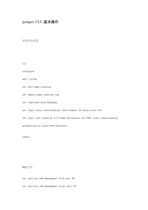
juniper CLI 基本操作系统基本配置:cliconfigureedit systemset host-name xiaoxiaoset domain-name set time-zone Asia/Shanghaiset login class xiaoxiaogroup idle-timeout 30 permissions allset login user xiaoxiao full-name fuxiaoxiaouid 2002 class xiaoxiaogroup authentication plain-text-passwordcommitWEB管理:set services web-management http port 80set services web-management https port 80set services web-management session idle-timeout 30 set services web-management session session-limit 30 Telnet配置:edit systemset services telnetset services telnet rate-limit 10set services telnet connection-limit 30日志管理:edit systemset syslog file messages any noticeset syslog archive size 1m files 20set syslog host 202.15.26.156.158 any anyset syslog console any noticeset syslog file messages archive size 2M files 20juniper os可以把syslog发送到console(控制台口)日志服务器,本地硬盘默认是存放到本地硬盘:/var/log 下set syslog console any notice 可以指定日志输出到控制台set syslog host 202.15.26.156.158 any any 可以指定日志输出到远程主机关闭日志从控制台输出delete syslog console any noticeSSH配置:edit systemset services sshset services ssh rate-limit 10set services ssh connection-limit 30SNMP配置:set snmp community key-string authorization read-only clients ipaddressset snmp community key-string authorization read-only clients default restrict set snmp community key-string authorization read-write clients ipaddressset snmp community key-string authorization read-only clients default restrict set snmp interface interfacelistset snmp trap-group groupname version [v1|v2|all] destination-port portnumber targets ipaddressset snmp trap-options source-address lo0例子:setsnmp community xiao3 authorization read-writeset snmp community xiao3 authorization read-write clients 192.168.1.200set snmp trap-group xiao5 version allset snmp trap-group xiao5 targets 192.168.1.200FTP:edit systemset services ftpset services ftp rate-limit 10set services ftp connection-limit 30 set name-server 192.168.1.1。
Juniper资料

Juniper资料HI,这是我学习JNO-341时做的一些摘录.大纲上的内容基本都有涉及,如果你想参加这个考试的话,我想对你会有帮助的.欢迎转摘,但请标名出处,尊重作者的劳动成果.如果有什么疑问的话,可以发送e-mail给我,希望能够帮得上忙,欢迎加入juniper学习交流群~ J *************************************************************** ****************Operating Juniper NetworksRouters in the EnterpriseJuniper Networks Enterprise Routers企业路由的位置:J系列路由器应用在小型企业M系列路由器应用在大型企业M系列和T系列路由器一般应用在网络服务提供商的网络中心M系列与J系列路由的主要不同点:M系列是基于硬件的转发,使用专门的ASICs来应用主要的硬件转发功能,分隔的控制和转发面板不会互相干扰,从而提高了运行性能, 保护了数据的稳定性.J系列是基于软件的控制和转发,使用了实时的操作系统,保证了包转发过程给予了最高的优先级别.基于软件的设计保持了低的消耗(cost)和更大的功能灵活性.J系列的版权保护:Juniper使用公钥(public-key)加密JUNOS软件,这意味着你无法在PC上运行此软件.J系列的主板的EPROM中写入了私钥(private key),这项保护措施确保JUNOS软件只运行在支持Juniper产品的硬件上.没有经过私钥认证,JUNOS软件不会转发包.分隔的控制和转发面板:路由引擎(RE):RE是平台的核心,它负责执行路由更新和系统管理.RE运行着多种协议并且管理受内存保护环境下的软件进程.RE是基于x86结构微处理器的一般用途电脑平台.RE包含路由器的主要转发表;通过一条内部链接到PFE.包转发引擎(PFE):PFE负责转发传送来的包通过路由器.PFE在J系列平台上使用实时线程,在M和T系列平台在使用ASICs.因为这个体系从包过滤中分隔了控制操作,像路由更新和系统管理,因此路由器具有更高的执行性能,甚至在基于软件的J系列PFE中也如此.PFE只能简单的做告诉它做的事情,这种低的智能性却提供了高的执行性能和稳定性.路由表和转发表:JUNOS软件路由协议进程(routing protocol process)允许多种路由协议运行在路由器上.路由协议进程开启所有配置的路由协议并处理所有的路由消息.路由进程包含一个或多个路由表,巩固了从所有路由协议学习来的路由信息.从这些路由信息中,路由协议进程决定到目的网络的活动路由,并把这些路由装入RE的转发表(FT).路由引擎:RE处理所有路由协议进程以及其他软件进程像控制路由器的接口,底盘组件,系统管理和接入路由器的用户.这些和PFE互相作用的路由和软件进程运行在JUNOS内核的最高层.所有从网络的路由协议包都直接到RE.RE通过提供一个准确的和最新的转发表和下载微代码(microcode)以及管理在PFE微代码中的软件进程来控制PFE.RE从PFE接收硬件和环境状态消息,并以它们为准.J系列软件体系:JUNOS软件是基于FreeBSD操作系统,开放式的源代码,可以增加特定的守护进程(daemon)来增加路由的功能。
juniper ssg 5常用CLI指南
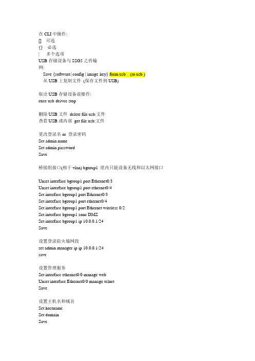
在CLI中操作:[] 可选{} 必选| 多个选项USB存储设备与SSG5之传输例:Save {software| config | image-key} form usb (to usb )从USB上复制文件(保存文件到USB)取出USB存储设备前操作:exce usb-deivce stop删除USB文件delete file usb:文件查看USB或内部get file usb:文件更改登录名or 登录密码Set admin nameSet admin passwordSave桥接组接口(相于vlan) bgroup1 组内只能设备无线和以太网接口Unset interface bgroup1 port Ethernet0/3Unset interface bgroup1 port ethernet0/4Set interface bgroup1 port Ethernet0/3Set interface bgroup1 port ethernet0/4Set interface bgroup1 port Ethernet wireless 0/2Set interface bgroup1 zone DMZSet interface bgroup1 ip 10.0.0.1/24Save设置登录防火墙网段set admin manager-ip ip 10.0.0.1/24save设置管理服务Set interface ethernet0/0 manage webUnset interface Ethernet0/0 manage telnetSave设置主机名和域名Set hostnameSet domainSave缺省路由Set route 0.0.0.0/0 interface Ethernet0/2 gateway ip 地址Save备份untrust 接口设置Set interface bgroup0 port ethernet0/4Set interface ethernet0/4 zone untrustSet interface Ethernet0/0 backup interface Ethernet0/4 type track-ip SaveISDN配置set interface bri0/0 dialer-enableset interface bri0/0 primary-number “123456”set interface bri0/0 encap pppset interface bri0/0 ppp profile isdnprofilesave。
- 1、下载文档前请自行甄别文档内容的完整性,平台不提供额外的编辑、内容补充、找答案等附加服务。
- 2、"仅部分预览"的文档,不可在线预览部分如存在完整性等问题,可反馈申请退款(可完整预览的文档不适用该条件!)。
- 3、如文档侵犯您的权益,请联系客服反馈,我们会尽快为您处理(人工客服工作时间:9:00-18:30)。
res<space>tart ro<space>uting g<space>racefully
Copyright © 2009 Juniper Networks, Inc.
Copyright © 2009 Juniper Networks, Inc.
4 | Copyright © 2009 Juniper Networks, Inc. |
层次化配置结构
配置结构采用树型构架,类似于UNIX/windows的 目录结构
5 | Copyright © 2009 Juniper Networks, Inc. |
层次化配置命令
使用edit来进入配置的层次 类似于UNIX的
cd 命令
edit system login user lab
使用up来返回上一层配置层次 类似于UNIX的
3 | Copyright © 2009 Juniper Networks, Inc. |
用户模式和配置模式之间切换
% % cli > configure # show configuration # exit > start shell % cli > exit % exit default when you login as “root”
Copyright © 2009 Juniper Networks, Inc.
10 | Copyright © 2009 Juniper Networks, Inc. |
管道符 |
>show interfaces | ?
>show interfaces | count
commit提交生效即可; 极大的简化了配置的时间和精力, 任何时间任何地点, 可以在1-2秒内恢复原 有配置; 支持一行一行察看命令的方式;
[edit] admin# show system domain-name ; time-zone Asia/Hong_Kong; root-authentication { encrypted-password "$1$Y1lF.qft$nKjoqliNCQ/b4ZpAbKgXz/"; ## SECRET-DATA } login { class netops { permissions view; } user jnpr {
统计输出行数
>show interfaces | match fxp1 包含fxp1的输出行 >show interfaces | find fxp1 从包含fxp1行以后的内容 >show interfaces | save filename 保存到文件
lab@M7i_GZ> show interfaces | save /var/tmp/in.txt Wrote 859 lines of output to '/var/tmp/in.txt'
12 | Copyright © 2009 Juniper Networks, Inc. |
配置文件的管理
配置文件可以直接存在本地或输出到外部主机;
可以随时保存50个配置文件(机器自动保存); 可以另存任意的配置文件(手工保存); 以上配置文件可以直接在设备上查看,也可以下载到PC中查看; 使用时直接load文件,
user@hostname%
进入用户模式,显示的提示符:>
user@hostname>
进入配置模式,显示的提示符:#
user@hostname#
初次配置防火墙: 管理员账号root,密码为空,进入的是shell模式,输入cli 命令进入用户模式
Copyright © 2009 Juniper Networks, Inc.
Copyright © 2009 Juniper Networks, Inc.
14 | Copyright © 2009 Juniper Networks, Inc. |
基本命令-rollback
使用
rollback 命令来恢复commit以前的配置 或者 rollback 0 恢复上次commit之前的配置 1 上两次commit之前的配置 ? 可以显示每次commit的时间,确定恢复那份配置
top
Less Specific
chassis firewall interfaces protocols system more…
alarm
clock
fpc
atm
e3
ethernet
sonet
t3
More Specific
Copyright © 2009 Juniper Networks, Inc.
基本命令-rename
ge-4/0/2 接口的地址被错误设置为10.73.24.103/24。 [edit interfaces] user@hostname# show
7 | Copyright © 2009 Juniper Networks, Inc. |
获取帮助
可以在命令行中任何地方输入
助 帮助内容取决于你在哪里输入? 命令行开始处输入”?” 显示最上层的帮助 命令最后输入”?” 显示下一层次的帮助 如 root@hostname>show ? 显示命令show命 令下一层可带参数 命令中间输入”?” 显示当前层次匹配的命令 root@hostname>s? 显示set、show、ssh、 start
Copyright © 2009 Juniper Networks, Inc.
13 | Copyright © 2009 Juniper Networks, Inc. |
加载配置文件
Configuration information can come from an ASCII file prepared offline
9 | Copyright © 2009 Juniper Networks, Inc. |
历史命令
用户模式和配置模式下都可以使用历史命令
上、下箭头键(VT100)
(Ctrl-P / Ctrl-N)
show
cli history (CLI mode only)
默认可以显示最后100条操作命令 <count> 最多显示count条记录
空格键用于补齐大部分 Tab
CLI 命令。
键不仅用于补齐 CLI 命令,还用于补齐文件名和 用户定义的变量,如策略名称、Zone名称和 IP 地址。
example :使用空格键和 Tab 键
输入以下命令,使用空格键将其补齐: sh<space>ow ro<space>ute
sh<space>ow ch<space>assis h<space>ardware
}
admin# show system | display set set system host-name JUNOS-lab set system domain-name set system time-zone Asia/Hong_Kong set system saved-core-context
Copyright © 2009 Juniper Networks, Inc.
2 | Copyright © 2009 Juniper Networks, Inc. |
JUNOS 提示符
默认通过Root账号登录,显示shell模式提示符:%
help
reference ?
命令参考说明
help
syslog <tag>
系统日志错误信息帮助 help
syslog CHASSISD_ANTICF_PIM_CHECK_FAILED
Copyright © 2009 Juniper Networks, Inc.
置
候选配置(Candidate
Config):进入配置模式修 改的配置,是活动配置的副本,执行commit命令成 为Active config | compare比较候选配置和
此外可通过执行show
活动配置之间的差异
Copyright © 2009 Juniper Networks, Inc.
Syntax load (replace | merge | override) filename
只改变candidate 配置 需要 commit 来生效 Use the load command to
Override 覆盖已经存在的配置 要覆盖整个配置,使用override 选项 merge 新的配置语句合并到已经存在的配置文件中 replace 用新的配置替代已经存在的配置
cd ..命令
使用top返回最上层
类似于UNIX的cd
/命令
Copyright © 2009 Juniper Networks, Inc.
6 | Copyright © 2009 Juniper Networks, Inc. |
命令补齐--TAB和空格键
rollback只是将配置恢复到Candidat配置e rollback rollback
总共可以恢复49份配置 rollback run
file show /config/juniper.conf.n.gz n为1-3,可以查看需要恢复配置的内容,对应于rollback 1-3 run file show /config/juniper.conf.gz 对应rollback 0