SFH618A-5X006中文资料
HT66FXX中文版详细资料
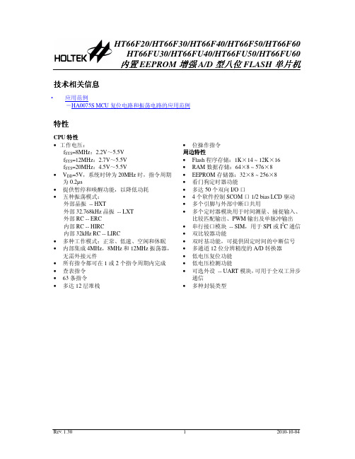
内置 EEPROM 增强 A/D 型八位 FLASH 单片机
技术相关信息
· 应用范例 -HA0075S MCU 复位电路和振荡电路的应用范例
特性
CPU 特性 • 工作电压:
这款单片机提供了丰富的 HXT、LXT、ERC、HIRC 和 LIRC 振荡器功能选项,且内建完整的系 统振荡器,无需外围元器件。其在不同工作模式之间动态切换的能力,为用户提供了一个优化单片 机操作和减少功耗的手段。
HT66FUx0 系列单片机内含 UART 模块,它可以支持诸如单片机之间的数据通信网络,低成本 PC 和外部设备间的数据连接,便携式和电池供电设备间的通信等。
HT66F30
2.2V~ 5.5V
2K×14
96×8
64×8
22
2
12-bit×8
10-bit CTM×1 10-bit ETM×1
√
HT66FU30
14
16DIP/NSOP/SSOP
—
4
20DIP/SOP/SSOP 24SKDIP/SOP/SSOP
√
24SKDIP/SOP
HT66F40
2.2V~ 5.5V
P C 1 /T P 1 B _ 1 /[S D O ]/S C O M 1 9 P C 0 /T P 1 B _ 0 /[S D I/S D A ]/S C O M 0 1 0
2 0 P A 1 /T P 1 A /A N 1 1 9 P A 2 /T C K 0 /C 0 + /A N 2 1 8 P A 3 /IN T 0 /C 0 -/A N 3 1 7 P A 4 /IN T 1 /T C K 1 /A N 4 1 6 P A 5 /C 1 X /S D O /A N 5 1 5 P A 6 /S D I/S D A /A N 6 1 4 P A 7 /S C K /S C L /A N 7 1 3 P B 5 /S C S /V R E F 1 2 P C 2 /P C K /C 1 + 1 1 P C 3 /P IN T /C 1 -
6187R10KL1.0LF;6187R5KL1.0LF;6187R10KL1.0;6187R5KL1.0;中文规格书,Datasheet资料
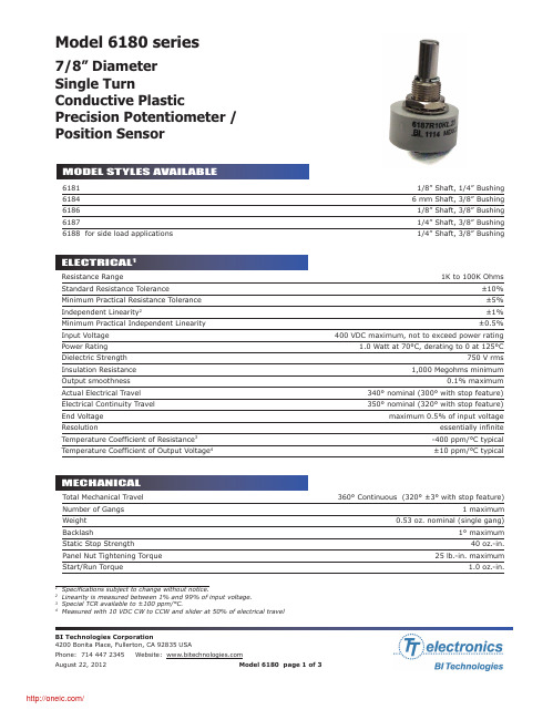
7/8” Diameter Single TurnConductive PlasticPrecision Potentiometer /Position SensorModel 6180 series61811/8” Shaft, 1/4” Bushing 6184 6 mm Shaft, 3/8” Bushing 61861/8” Shaft, 3/8” Bushing 61871/4” Shaft, 3/8” Bushing 6188 for side load applications1/4” Shaft, 3/8” BushingTotal Mechanical Travel 360° Continuous (320° ±3° with stop feature)Number of Gangs 1 maximumWeight 0.53 oz. nominal (single gang)Backlash1° maximumStatic Stop Strength 40 oz.-in.Panel Nut Tightening Torque 25 lb.-in. maximumStart/Run Torque1.0 oz.-in.11Specifications subject to change without notice.2Linearity is measured between 1% and 99% of input voltage.3Special TCR available to ±100 ppm/°C.4Measured with 10 VDC CW to CCW and slider at 50% of electrical travelResistance Range1K to 100K OhmsStandard Resistance Tolerance±10% Minimum Practical Resistance Tolerance ±5%Independent Linearity 2±1%Minimum Practical Independent Linearity ±0.5%Input Voltage 400 VDC maximum, not to exceed power ratingPower Rating 1.0 Watt at 70°C, derating to 0 at 125°CDielectric Strength 750 V rmsInsulation Resistance 1,000 Megohms minimumOutput smoothness 0.1% maximumActual Electrical Travel 340° nominal (300° with stop feature)Electrical Continuity Travel 350° nominal (320° with stop feature)End Voltage maximum 0.5% of input voltageResolutionessentially infinite Temperature Coefficient of Resistance 3-400 ppm/°C typical Temperature Coefficient of Output Voltage 4±10 ppm/°C typicalOperating Temperature Range-40°C to +125°C dynamic, -65°C to +125°C staticTemperature Cycling 5 cycles, -65°C to +125°C, maximum 10% ΔRShock 6 ms Saw-tooth, 100 G’s, 0.1 ms maximum discontinuityVibration10 G’s, 10 to 500 Hz, maximum 2% ΔR, 0.1 ms maximum discontinuityMoisture Resistancefive 24 hour cycles, maximum 25% ΔR High Temperature Exposure 1,000 hours at 125°C, maximum 0.5% ΔV RRotational Life 5 million shaft revolutions Rotational Load Life5 million shaft revolutions, maximum 10% ΔRIngress Protection Rating (IP Code)IP40Model Series Resistance PrefixResistance ValueOptional Feature Code (see table)Optional Non-standard Tolerance6187 R 10K T5 L1.0 xx LFLinearityOptional RoHS Compliant Product CodeSTANDARD RESISTANCE VALUESWhen multiple feature codes are used the P/N shall be in thesame sequence as listed in this table (top to bottom).分销商库存信息:OPTEK-TECHNOLOGY6187R10KL1.0LF6187R5KL1.0LF6187R10KL1.0 6187R5KL1.0。
XC6106F618资料

1/26XC6101_07_XC6111_17 ETR0207_009Preliminary◆CMOS Voltage Detector◆Manual Reset Input ◆Watchdog Functions ◆Built-in Delay Circuit ◆Detect Voltage Range: 1.6~5.0V, ± 2% ◆Reset Function is Selectable V DFL (Low When Detected) V DFH (High When Detected)■GENERAL DESCRIPTION The XC6101~XC6107, XC6111~XC6117 series aregroups of high-precision, low current consumption voltage detectors with manual reset input function and watchdog functions incorporating CMOS process technology. The series consist of a reference voltage source, delay circuit, comparator, and output driver.With the built-in delay circuit, the XC6101 ~ XC6107, XC6111 ~ XC6117 series’ ICs do not require any external components to output signals with release delay time. Moreover, with the manual reset function, reset can be asserted at any time. The ICs produce two types of output; V DFL (low when detected) and V DFH (high when detected).With the XC6101 ~ XC6105, XC6111 ~ XC6115 series’ ICs, the WD pin can be left open if the watchdog function is not used. Whenever the watchdog pin is opened, the internal counter clears before the watchdog timeout occurs. Since the manual reset pin is internally pulled up to the V IN pin voltage level, the ICs can be used with the manual reset pin left unconnected if the pin is unused.The detect voltages are internally fixed 1.6V ~ 5.0V in increments of 100mV, using laser trimming technology. Six watchdog timeout period settings are available in a range from 6.25msec to 1.6sec. Seven release delay time 1 are available in a range from 3.13msec to 1.6sec.■APPLICATIONS●Microprocessor reset circuits●Memory battery backup circuits ●System power-on reset circuits ●Power failure detection■TYPICAL APPLICATION CIRCUIT* Not necessary with CMOS output products.■FEATURESDetect Voltage Range: 1.6V ~ 5.0V, +2% (100mV increments)Hysteresis Range : V DF x 5%, TYP .(XC6101~XC6107)V DF x 0.1%, TYP .(XC6111~XC6117)Operating Voltage Range : 1.0V ~ 6.0V Detect Voltage Temperature Characteristics : +100ppm/O C (TYP .) Output Configuration : N-channel open drain,CMOSWatchdog Pin : Watchdog inputIf watchdog input maintains ‘H’ or ‘L’ within the watchdog timeout period, a reset signal is output to the RESET output pinManual Reset Pin : When driven ‘H’ to ‘L’levelsignal, the MRB pin voltage asserts forced reset on theoutput pin.Release Delay Time : 1.6sec, 400msec, 200msec,100msec, 50msec, 25msec, 3.13msec (TYP .) can be selectable.Watchdog Timeout Period : 1.6sec, 400msec, 200msec,100msec, 50msec,6.25msec (TYP .) can be selectable.■TYPICAL PERFORMANCE CHARACTERISTICS ●Supply Current vs. Input Voltage* ‘x’ represents both ‘0’ and ‘1’. (ex. XC61x1⇒XC6101 and XC6111)2/26XC6101~XC6107, XC6111~XC6117 SeriesPIN NUMBERXC6101, XC6102 XC6103 XC6104, XC6105XC6106, XC6107XC6111, XC6112 XC6113 XC6114, XC6115XC6116, XC6117SOT-25 USP-6C SOT-25 USP-6C SOT-25 USP-6C SOT-25USP-6CPIN NAMEFUNCTION1 4 - - 1 4 1 4 R ESETB Reset Output(V DFL : Low Level When Detected)2 5 2 5 2 5 2 5 V SSGround3 2 3 2 - -4 1 M RB ManualReset 4 1 4 1 4 1 - - WDWatchdog5 6 5 6 5 6 5 6 V IN Power Input - - 1 4 3 2 3 2 RESETReset Output (V DFH: High Level When Detected)■PIN CONFIGURATION SOT-25 (TOP VIEW)MRBV IN WD RESETBV SSMRBWD RESETV SSV IN RESETWD RESETBV SS V IN SOT-25 (TOP VIEW)RESETMRB RESETBV SS V IN SOT-25 (TOP VIEW) ■PIN ASSIGNMENT●SOT-25XC6101, XC6102 SeriesXC6111, XC6112 SeriesSOT-25 (TOP VIEW)XC6103 & XC6113 SeriesXC6104, XC6105 Series XC6114, XC6115 SeriesXC6106, XC6107 Series XC6116, XC6117 Series●USP-6CXC6101, XC6102 Series XC6111, XC6112 SeriesXC6103 & XC6113 SeriesXC6104, XC6105 Series XC6114, XC6115 SeriesXC6106, XC6107 Series XC6116, XC6117 SeriesUSP-6C (BOTTOM VIEW)USP-6C (BOTTOM VIEW)USP-6C (BOTTOM VIEW)USP-6C (BOTTOM VIEW)* The dissipation pad for the USP-6C package should be solder-plated in recommended mount pattern and metal masking so as to enhance mounting strength and heat release. If the pad needs to be connected to other pins, it should be connected to the V SS pin.3/26XC6101 ~ XC6107, XC6111~ XC6117SeriesRESET OUTPUTSERIES WATCHDOGMANUAL RESET V DFL (RESETB)V DFH (RESET)XC6101 XC6111 Available Available CMOS - XC6102XC6112AvailableAvailableN-channel open drain-XC6103 XC6113 Available Available - CMOS XC6104 XC6114 Available Not AvailableCMOS CMOS XC6105 XC6115 Available Not Available N-channel open drain CMOS XC6106 XC6116 Not Available AvailableCMOSCMOS XC6107XC6117Not AvailableAvailableN-channel open drainCMOSDESIGNATORDESCRIPTIONSYMBOLDESCRIPTION0 : V DF x 5% (TYP .) with hysteresis ① Hysteresis Range1 : V DF x 0.1% (TYP .) without hysteresis② Functions and Type of Reset Output1 ~ 7: Watchdog and manual functions, and reset output type as per Selection Guide in the above chartA : 3.13msec (TYP .)B : 25msec (TYP .) C: 50msec (TYP .) D : 100msec (TYP .) E : 200msec (TYP .) F : 400msec (TYP .) ③ Release Delay Time * H : 1.6sec (TYP .)0 : No WD timeout period forXC6106, XC6107, XC6116, XC6117 Series 1: 6.25msec (TYP .) 2 : 50msec (TYP .) 3 : 100msec (TYP .) 4 : 200msec (TYP .) 5 : 400msec (TYP .) ④ Watchdog Timeout Period6: 1.6sec (TYP .) ⑤⑥ Detect Voltage 16 ~ 50: Detect voltageex.) 4.5V: ⑤⇒4, ⑥⇒5M : SOT-25 ⑦ Package E : USP-6C R : Embossed tape, standard feed ⑧ Device OrientationL: Embossed tape, reverse feed* Please set the release delay time shorter than or equal to the watchdog timeout period. ex.) XC6101D427MR or XC6101D327MR■PRODUCT CLASSIFICATION ●Selection Guide ●Ordering Information XC61①②③④⑤⑥⑦⑧4/26XC6101~XC6107, XC6111~XC6117 Series■PACKAGING INFORMATION●SOT-25●USP-6C5/26XC6101 ~ XC6107, XC6111~ XC6117Series④ Represents production lot number0 to 9 and A to Z and inverted 0 to 9 and A to Z repeated. (G, I, J, O, Q, W expected.) * ‘X’ represents both ‘0’ and ‘1’. (ex. XC61X1⇒XC6101 and XC6111)■MARKING RULE●SOT-25①②③④SOT-25 (TOP VIEW)6/26XC6101~XC6107, XC6111~XC6117 Series① Represents product series② Represents release delay time MARK RELEASE DELAY TIME PRODUCT SERIES A 3.13msec XC61XxAxxxxx B 25msec XC61XxBxxxxx C 50msec XC61XxCxxxxx D 100msec XC61XxDxxxxx E 200msec XC61XxExxxxx F 400msec XC61XxFxxxxx H 1.6sec XC61XxHxxxxx③ Represents watchdog timeout period MARK WATCHDOG TIMEOUT PERIOD PRODUCT SERIES 0 XC61X6, XC61X7 series XC61Xxx0xxxx 1 6.25msec XC61Xxx1xxxx 2 50msec XC61Xxx2xxxx 3 100msec XC61Xxx3xxxx 4 200msec XC61Xxx4xxxx 5 400msec XC61Xxx5xxxx 6 1.6sec XC61Xxx6xxxx④⑤ Represents detect voltage MARK④ ⑤DETECT VOLTAGE (V)PRODUCT SERIES3 3 3.3 XC61Xxxx33xx 5 0 5.0XC61Xxxx50xx⑥ Represents production lot number0 to 9 and A to Z repeated. (G, I, J, O, Q, W excepted.)* No character inversion used. ** ‘X’ represents both ‘0’ and ‘1’. (ex. XC61X1⇒XC6101 and XC6111)MARK PRODUCT SERIES MARK PRODUCT SERIES 3 XC6101xxxxxx 8 XC6111xxxxxx 4 XC6102xxxxxx 9 XC6112xxxxxx 5 XC6103xxxxxx A XC6113xxxxxx 6 XC6104xxxxxx B XC6114xxxxxx 7 XC6105xxxxxx C XC6115xxxxxx 3 XC6106xxxxxx 8 XC6116xxxxxx 4 XC6107xxxxxx 9 XC6117xxxxxx■MARKING RULE (Continued)●USP-6CUSP-6C (TOP VIEW)7/26XC6101 ~ XC6107, XC6111~ XC6117Series■BLOCK DIAGRAMS●XC6101, XC6111 Series●XC6102, XC6112 Series●XC6103, XC6113 Series8/26XC6101~XC6107, XC6111~XC6117 Series■BLOCK DIAGRAMS (Continued)●XC6107, XC6117 Series●XC6106, XC6116 Series●XC6105, XC6115 Series●XC6104, XC6114 Series9/26XC6101 ~ XC6107, XC6111~ XC6117SeriesPARAMETERSYMBOL RATINGSUNITSV INV SS -0.3 ~ 7.0 VM RBV SS -0.3 ~ V IN +0.3 VInput Voltage WD V SS -0.3 ~ 7.0V Output Current I OUT 20 mACMOS Output RESETB/RESET V SS -0.3 ~ V IN +0.3Output Voltage N-ch Open Drain Output RESETB V SS -0.3 ~ 7.0VSOT-25 250Power Dissipation USP-6C Pd 100mWOperational Temperature Range Topr -40 ~ +85 OCStorage Temperature Range Tstg -40 ~ +125 OC■ABSOLUTE MAXIMUM RATINGSTa = 25O C10/26XC6101~XC6107, XC6111~XC6117 SeriesNOTE:*1: XC6101~XC6107 (with hysteresis) *2: XC6111~XC6117 (without hysteresis)*3: ‘X’ represents both ‘0’ and ‘1’. (ex. XC61X1⇒XC6101 and XC6111) *4: V DF(T): Setting detect voltage*5: If only “V DF ” is indicated, it represents both V DFL (low when detected) and V DFH (high when detected).PARAMETERSYMBOLCONDITIONSMIN.TYP .MAX. UNITS CIRCUITDetect Voltage V DFL V DFHV DF(T)× 0.98V DF(T) V DF(T)× 1.02 V 1 Hysteresis Range XC6101~XC6107 (*1) V HYS V DF × 0.02V DF × 0.05 V DF× 0.08 V 1Hysteresis Range XC6111~XC6117 (*2) V HYS 0 V DF × 0.001 V DFx 0.01V 1V IN =V DF(T)×0.9V - 5 11 V IN =V DF(T)×1.1V- 10 16 XC61X1/XC61X2/XC61X3XC61X4/XC61X5 (*3)(The MRB & the WD Pin: No connection) V IN =6.0V - 1218 V IN =V DF(T)×0.9V - 4 10 V IN =V DF(T)×1.1V - 8 14 Supply Current I SS XC61X6/XC61X7 (*3)(The MRB Pin: No connection)V IN = 6.0V - 1016 µA 2Operating Voltage V IN 1.0 - 6.0 V 1VIN = 1.0V 0.15 0.5 -V IN =2.0V (V DFL(T)> 2.0V) 2.0 2.5 - V IN =3.0V (V DFL(T) >3.0V) 3.0 3.5 -N-ch.V DS = 0.5V V IN =4.0V (V DFL(T) >4.0V) 3.5 4.0 - 3 V DFL Output Current (RESETB) I RBOUTCMOS,P-chV DS = 0.5V V IN = 6.0V - - 1.1 -0.8 mA 4 N-chV DS = 0.5VV IN =6.0V 4.4 4.9 - 3V IN =1.0V - - 0.08 - 0.02 V IN =2.0V (V DFH(T)> 2.0V)- - 0.50 - 0.30 V IN =3.0V (V DFH(T)>3.0V)- - 0.75 - 0.55V DFHOutput Current (RESET) I ROUT P-ch. V DS = 0.5V V IN =4.0V (V DFH(T)>4.0V)- - 0.95 - 0.75 mA 4Temperature Characteristics △V DF / △Topr ・V DF -40OC < Topr < 85 O C - +100 - ppm / O C12 3.13 5 13 25 3825 50 75 60 100 140 120 200 280 240 400 560Release Delay Time(V DF <1.8V)T DR Time until V IN is increased from1.0V to2.0Vand attains to the release time level,and the Reset output pin inverts.960 1600 2240 ms 5 2 3.13 5 13 25 38 25 50 7560 100 140 120 200 280 240 400 560 Release Delay Time(V DF >1.9V)T DRTime until V IN is increased from1.0V to (V DF x1.1V) and attains to the releasetime level,and the Reset output pin inverts. 960 1600 2240ms 5 Detect Delay Time T DFTime until V IN is decreased from 6.0V to 1.0V and attains to the detect voltage level, and the Reset output pin detectswhile the WD pin left opened.- 3 30 µs 5V DFL /V DFH CMOS Output Leak CurrentI LEAK V IN =6.0V, RESETB=6.0V (V DFL ) V IN =6.0V, RESET=0V (V DFH )- 0.01 - µA 3V DFL N-ch Open DrainOutput Leak CurrentI LEAKV IN =6.0V, RESETB=6.0V-0.010.10µA 3■ELECTRICAL CHARACTERISTICS●XC6101~XC6107, XC6111~XC6117 SeriesTa = 25O CSeriesPARAMETERSYMBOL CONDITIONS MIN.TYP . MAX. UNITS CIRCUIT3.13 6.25 9.38 25 50 7560 100 140 120 200 280240 400 560 Watchdog Timeout Period (V DF <1.8V)T WDTime until V IN increases form1.0V to2.0V andthe Reset output pin is released to go into the detection state. (WD=V SS )960 1600 2240 ms 6 3.13 6.25 9.38 25 50 75 60 100 140 120 200 280240 400 560 Watchdog Timeout Period (V DF >1.9V)T WDTime until V IN increases form1.0V to (V DF x1.1V)and the Reset output pin is released to go into the detection state. (WD=V SS )960 1600 2240 ms 6 WatchdogMinimum Pulse Width T WDIN V IN =6.0V,Apply pulse from 6.0V to 0Vto the WD pin. 300 - - ns 7 Watchdog High Level VoltageV WDH V IN =V DF x 1.1V ~ 6.0V V IN x 0.7- 6 V 7 Watchdog Low Level Voltage V WDL V IN =V DF x 1.1V ~ 6.0V0 - V IN x 0.3 V 7 V IN =6.0V, V WD =6.0V (Avg. when peak )- 12 19Watchdog Input Current I WD V IN =6.0V, V WD =0V (Avg. when peak) - 19 -12 -µA 8 Watchdog Input ResistanceR WDV IN =6.0V, V WD =0V, R WD =V IN / |I WD |315500880k Ω8PARAMETERSYMBOL CONDITIONS MIN.TYP . MAX.UNITS CIRCUITMRBHigh Level VoltageV MRH V IN =V DF x1.1V ~ 6.0V 1.4 - V IN 9MRBLow Level VoltageV MRL V IN =V DF x1.1V ~ 6.0V-0.35 V9MRBPull-up Resistance R MR V IN =6.0V, MRB=0V, R MR =V IN / |I MRB | 1.6 2.4 3.0 M Ω 10 MRB Minimum Pulse Width (*3) XC6101~XC6105 XC6111~XC6115 T MRINV IN =6.0V,Apply pulse from 6.0V to 0V tothe MRB pin 2.8 - -MRB Minimum Pulse Width (*4) XC6106, XC6107 XC6116, XC6117T MRIN V IN =6.0V,Apply pulse from 6.0V to 0V tothe MRB pin1.2 - -µs11●XC6101 ~ XC6103, XC6106 ~ XC6107, XC6111 ~ XC6113, XC6116 ~ XC6117 Series NOTE:*1: V DF(T): Setting detect voltage *2: If only “V DF ” is indicated, it represents both V DFL (low when detected) and V DFH (high when detected). *3: Watchdog function is available. *4: Watchdog function is not available.Ta = 25O CTa = 25O C ■ELECTRICAL CHARACTERISTICS (Continued)●XC6101~XC6105, XC6111~XC6115 Series■OPERATIONAL EXPLANATIONThe XC6101~XC6107, XC6111~XC6117 series compare, using the error amplifier, the voltage of the internal voltage reference source with the voltage divided by R1, R2 and R3 connected to the V IN pin. The resulting output signal from the error amplifier activates the watchdog logic, manual reset logic, delay circuit and the output driver. When the V IN pin voltage gradually falls and finally reaches the detect voltage, the RESETB pin output goes from high to low in the case of the V DFL type ICs, and the RESET pin output goes from low to high in the case of the V DFH type ICs.<RESETB / RESET Pin Output Signal>* V DFL (RESETB) type - output signal: Low when detected.The RESETB pin output goes from high to low whenever the V IN pin voltage falls below the detect voltage, or whenever the MRB pin is driven from high to low. The RESETB pin remains low for the release delay time (T DR) after the V IN pin voltage reaches the release voltage. If neither rising nor falling signals are applied to the WD pin within the watchdog timeout period, the RESETB pin output remains low for the release delay time (T DR), and thereafter the RESET pin outputs high level signal. * V DFH (RESET) type – output signal: High when detected.The RESET pin output goes from low to high whenever the V IN pin voltage falls below the detect voltage, or whenever the MRB pin is driven from high to low. The RESET pin remains high for the release delay time (T DR) after the V IN pin voltage reaches the release voltage. If neither rising nor falling signals are applied to the WD pin within the watchdog timeout period, the V OUT pin output remains high for the release delay time (T DR), and thereafter the RESET pin outputs low level signal.<Hysteresis>When the internal comparator output is high, the NMOS transistor connected in parallel to R3 is turned ON, activating the hysteresis circuit. The difference between the release and detect voltages represents the hysteresis range, as shown by the following calculations:V DF (detect voltage) = (R1+R2+R3) x Vref(R2+R3)V DR (release voltage) = (R1+R2) x Vref(R2)V HYS (hysteresis range)=V DR-V DF (V)V DR > V DF* Detect voltage (V DF) includes conditions of both V DFL (low when detected) and V DFH (high when detected).* Please refer to the block diagrams for R1, R2, R3 and Vref.Hysteresis range is selectable from V DF x 0.05V (XC6101~XC6107) or V DF x 0.001V (XC6111~XC6117).<Watchdog (WD) Pin>The XC6101~XC6107, XC6111~XC6117 series use a watchdog timer to detect malfunction or “runaway” of the microprocessor. If neither rising nor falling signals are applied from the microprocessor within the watchdog timeout period, the RESETB/RESET pin output maintains the detection state for the release delay time (T DR), and thereafter the RESET/RESETB pin output returns to the release state (Please refer to the FUNCTION CHART). The timer in the watchdog is then restarted. Six watchdog timeout period settings are available in 1.6sec, 400msec, 200msec, 100msec, 50msec, 6.25msec.<MRB Pin>Using the MRB pin input, the RESET/RESETB pin signal can be forced to the detection state. When the MRB pin is driven from high to low, the RESETB pin output goes from high to low in the case of the V DFL type ICs, and the RESET pin output goes from low to high in the case of the V DFH type. Even after the MRB pin is driven back high, the RESET/RESETB pin output maintains the detection state for the release delay time (T DR). Since the MRB pin is internally pulled up to the V IN pin voltage level, leave the MRB pin open if unused (Please refer to the FUNCTION CHART). A diode, which is an input protection element, is connected between the MRB pin and V IN pin. Therefore, if the MRB pin is applied voltage that exceeds V IN, the current will flow to V IN through the diode. Please use this IC within the stated maximum ratings (V SS -0.3 ~ V IN+0.3) on the MRB pin.<Release Delay Time>Release delay time (T DR) is the time that elapses from when the V IN pin reaches the release voltage, or when the watchdog timeout period expires with no rising signal applied to the WD pin, until the RESET/RESETB pin output is released from the detection state. Seven release delay time (T DR) watchdog timeout period settings are available in 1.6sec, 400msec, 200msec, 100msec, 50msec, 25msec, 3.13msec.<Detect Delay Time>Detect Delay Time (T DF) is the time that elapses from when the V IN pin voltage falls to the detect voltage until the RESET/ RESETB pin output goes into the detection state.Series■TIMING CHARTS●CMOS Output●T DF (CMOS Output)VINVDFL LevelGNDVIN Level VDFL Level GNDVIN x 0.1V■NOTES ON USE1. Please use this IC within the stated maximum ratings. Operation beyond these limits may cause degrading or permanent damage to the device.2. When a resistor is connected between the V IN pin and the input, the V IN voltage drops while the IC is operating and a malfunction may occur as a result of the IC’s through current. For the CMOS output products, the V IN voltage drops while the IC is operating and malfunction may occur as a result of the IC’s output current. Please be careful with using the XC6111~XC6117 series (without hysteresis).3. In order to stabilize the IC’s operations, please ensure that the V IN pin’s input frequency’s rise and fall times are more than 1 µ sec/V.4. Noise at the power supply may cause a malfunction of the watchdog operation or the circuit. In such case, please strength the line between V IN and the GND pin and connect about 0.22µF of a capacitor between the V IN pin and the GND pin.5. Protecting against a malfunction while the watchdog time out period, an ignoring time (no reaction time) occurs to the rise and fall times. Referring to the figure below, the ignoring time (no reaction time) lasts for 900µsec at maximum.GNDGNDGNDVIN Pin Wave FormWD Pin Wave FormRESETB Pin Wave Form (VDFL)SeriesPIN NAMELOGIC CONDITIONSH V IN >V DF +V HYS V IN L V IN <V DF H MRB>1.40V MRBL MRB<0.35V H When keeping W D >V WDH more than T WD L When keeping W D <V WDL more than T WD L → H V WDL → V WDH , T WDIN >300nsec WDH → L V WDH →V WDH , T WDIN >300nsecV IN MRB WD RESETB (*2) H HH LRepeat detect and release (H →L →H)H OpenH L → HH H or Open H → L H HLL *1 LV IN MRB WD RESETB (*3) H HH LRepeat detect and release (L →H →L)H OpenH L → HH H or Open H → L L HLL *1 HV IN WD RESETB (*2) RESET (*3) H HH L Repeat detect and release (H →L →H)Repeat detect and release (L →H →L)H OpenH L → HH H → L H L HL*1 L HV IN MRB RESETB (*2)RESET (*3)H H or Open H LH LL L H■PIN LOGIC CONDITIONSNOTE:*1: If only “V DF ” is indicated, it represents both V DFL (low when detected) and V DFH (high when detected).*2: For the details of each parameter, please see the electrical characteristics. V DF : Detect VoltageV HYS : Hysteresis RangeV WDH : WD High Level Voltage V WDL: WD Low Level Voltage T WDIN : WD Pulse Width T WD : WD Timeout Period■FUNCTION CHART●XC6103/XC61113 Series●XC6104/XC61114, XC6105/XC6115 Series●XC6106/XC61116, XC6107/XC6117 Series●XC6101/XC61111, XC6102/6112 Series*1: Including all logic of WD (WD=H, L, L →H, H →L, OPEN). *2: When the RESETB is High, the circuit is in the release state. When the RESETB is Low, the circuit is in the detection state. *3: When the RESET is High, the circuit is in the release state. When the RESET is Low, the circuit is in the detection state.■TEST CIRCUITSCircuit 1Circuit 2Circuit 3Circuit 4Series ■TEST CIRCUITS (Continued)Circuit 5Circuit 6Circuit 7■TEST CIRCUITS (Continued)Circuit 8Circuit 9Circuit 10Circuit 11Series■TYPICAL PERFORMANCE CHARACTERISTICS(1.1) Supply Current vs. Input Voltage(1.2) Supply Current vs. Input Voltage■TYPICAL PERFORMANCE CHARACTERISTICS (Continued)(2) Detect, Release Voltage vs. Ambient Temperature(1.2) Supply Current vs. Input Voltage (Continued)Series■TYPICAL PERFORMANCE CHARACTERISTICS (Continued) (3-1) Output Voltage vs. Input Voltage (V DFL ) (3.1) Detect, Release Voltage vs. Input Voltage (V DFL )(3.2) Detect, Release Voltage vs. Input Voltage (V DFH )■TYPICAL PERFORMANCE CHARACTERISTICS (Continued)(4) N-ch Driver Output Current vs. V DSSeries(6) P-ch Driver Output Current vs. Input Voltage 1■TYPICAL PERFORMANCE CHARACTERISTICS (Continued)(8) Release Delay Time vs. Ambient Temperature(7) P-ch Driver Output Current vs. Input Voltage 2■TYPICAL PERFORMANCE CHARACTERISTICS (Continued) (10) Release Delay Time vs. Input Voltage(11) Watchdog Timeout Period vs. Input VoltageSeries■TYPICAL PERFORMANCE CHARACTERISTICS (Continued)(14) MRB Low Level Voltage vs. Ambient Temperature(15) MRB High Level Voltage vs. Ambient Temperature* ‘X’ represents both ‘0’ and ‘1’. (ex. XC61X1⇒XC6101 and XC6111)。
Endress+Hauser Liquiphant FailSafe XA00661F-A 安全说明
Products Solutions Services XA00661F-A/00/B2/01.1271188028Safety InstructionsLiquiphant FailSafeFTL80, FTL81, FTL85Ex nA IIC T6...T2 Ga/GcEN Document: XA00661F-ASafety instructions for electrical apparatus for explosion-hazardous areas→ 3ZH文档资料代号:XA00661F-A防爆危险区中使用的电气设备的安全指南→ 13XA00661F-A Liquiphant FailSafe 2Endress+HauserLiquiphant FailSafe XA00661F-AEndress+Hauser 3Liquiphant FailSafe FTL80, FTL81, FTL85Table of ContentsAssociated documentation . . . . . . . . . . . . . . . . . . . . . . . . . . . . . . . . . . . . . . . . . . . . . . . . . . . .4Supplementary documentation . . . . . . . . . . . . . . . . . . . . . . . . . . . . . . . . . . . . . . . . . . . . . . . .4Manufacturer's certificates . . . . . . . . . . . . . . . . . . . . . . . . . . . . . . . . . . . . . . . . . . . . . . . . . . . .4Extended order code . . . . . . . . . . . . . . . . . . . . . . . . . . . . . . . . . . . . . . . . . . . . . . . . . . . . . . . . .4Safety instructions: General . . . . . . . . . . . . . . . . . . . . . . . . . . . . . . . . . . . . . . . . . . . . . . . . . . .6Safety instructions: Special conditions . . . . . . . . . . . . . . . . . . . . . . . . . . . . . . . . . . . . . . . . . .6Safety instructions: Installation . . . . . . . . . . . . . . . . . . . . . . . . . . . . . . . . . . . . . . . . . . . . . . . .7Safety instructions: Zone 0 . . . . . . . . . . . . . . . . . . . . . . . . . . . . . . . . . . . . . . . . . . . . . . . . . . . .8Explosion protection with heat insulation . . . . . . . . . . . . . . . . . . . . . . . . . . . . . . . . . . . . . . .8Temperature tables . . . . . . . . . . . . . . . . . . . . . . . . . . . . . . . . . . . . . . . . . . . . . . . . . . . . . . . . . .8Connection data . . . . . . . . . . . . . . . . . . . . . . . . . . . . . . . . . . . . . . . . . . . . . . . . . . . . . . . . . . . . .11XA00661F-A Liquiphant FailSafe4Endress+HauserAssociated documentationThis document is an integral part of the following Operating Instructions:BA01037F/00The Operating Instructions pertaining to the device apply.Supplementary documentation Explosion-protection brochure:CP00021Z/11The Explosion-protection brochure is available:•In the download area of the Endress+Hauser website: → Download → Advanced → Documentation Code: CP00021Z•On the CD for devices with CD-based documentationManufacturer's certificates NEPSI Declaration of Conformity Certificate number:GYJ14.1057XAffixing the certificate number certifies conformity with the standards under (depending on the device version).•GB3836.1-2010•GB3836.8-2003•GB3836.20-2010Extended order codeThe extended order code is indicated on the nameplate, which is affixed to the device in such a way that it is clearly visible. Additional information about the nameplate is provided in the associated Operating Instructions.Structure of the extended order code•Basic specificationsThe features that are absolutely essential for the device (mandatory features) are specified in the basic specifications. The number of positions depends on the number of features available. The selected option of a feature can consist of several positions.•Optional specificationsThe optional specifications describe additional features for the device (optional features). The number of positions depends on the number of features available.The features have a 2-digit structure to aid identification (e.g. JA). The first digit (ID) stands for the feature group and consists of a number or a letter (e.g. J = test, certificate). The second digit constitutes the value that stands for the feature within the group (e.g. A = 3.1 material (wetted parts), inspection certificate).More detailed information about the device is provided in the following tables. These tables describe the individual positions and IDs in the extended order code which are relevant to hazardous locations.FTL8x-*************+A*B*C*D*E*F*G*..------------------------------------------------------------------Device typeBasic specificationsOptional specifications* =PlaceholderAt this position, an option (number or letter) selected from the specification is displayed instead of the placeholders.Liquiphant FailSafe XA00661F-AEndress+Hauser 5Device type: FTL80, FTL81, FTL85Basic specificationsOptional specificationsPosition Selected option Description1, 2ApprovalFTL8x:NL Ex nA IIC T6...T2 Ga/Gc 3Electronics; Output FTL8x:S FEL85; 2-wire, 4-20 mA 4Display; Operating FTL8x:A LED; switch5HousingFTL8x:CD EH IF17 Alu, IP66/67 NEMA Type 4X Encl.F13 Alu, IP66/68 NEMA Type 4X/6P Encl.T13 Alu, separate conn. compartment, IP66/68 NEMA Type 4X/6P Encl.F15 316L hygiene, IP66/67 NEMA Type 4X Encl.F27 316L, IP66/68 NEMA Type 4X/6P Encl.6Electrical ConnectionFTL8x:AB C D E Gland M20Thread M20Thread G1/2Thread NPT1/2Thread NPT3/47ApplicationFTL80:ACD YProcess max. 150 °C/302 °F, 64 bar/928 psi Process max. 230 °C/446 °F, 100 bar/1450 psi; incl. gas-tight feed throughProcess max. 280 °C/536 °F, 100 bar/1450 psi; incl. gas-tight feed throughProcess max. 300 °C/572 °F, 100 bar/1450 psi FTL81:AB CD YProcess max. 150 °C/302 °F, 64 bar/928 psi Process max. 150 °C/302 °F, 100 bar/1450 psi Process max. 230 °C/446 °F, 100 bar/1450 psi; incl. gas-tight feed throughProcess max. 280 °C/536 °F, 100 bar/1450 psi; incl. gas-tight feed throughProcess max. 300 °C/572 °F, 100 bar/1450 psi FTL85:NP TECTFE, Process max. 120 °C/248 °F, 40 bar/580 psi PFA, Process max. 150 °C/302 °F, 40 bar/580 psi Enamel, Process max. 150 °C/302 °F, 25 bar/362 psi 9Surface RefinementFTL85:NP Q R TCoating ECTFECoating PFA (Edlon)Coating PFA (RubyRed)Coating PFA (conductive)Coating EnamelID Selected option DescriptionMxSensor DesignFTL8x:MPMR MS Ambient temperature –50 °C/–58 °F Temperature separatorPressure tight feed through, incl. temperature separator Nx Accessory MountedFTL8x:NCND NE NHCover, housing F17 Alu, window Cover, housing F13 Alu, window Cover, housing T13 Alu, window Cover, housing F15 316L, windowXA00661F-A Liquiphant FailSafe6Endress+HauserSafety instructions:General•Staff must meet the following conditions for mounting, electrical installation, commissioning and maintenance of the device:–Be suitably qualified for their role and the tasks they perform –Be trained in explosion protection –Be familiar with national regulations•For installation, use and maintenance of the device, users must also observe the requirements stated in the Operating Instructions and the standards:–GB50257-1996: "Code for construction and acceptance of electric device for explosion atmospheres and fire hazard electrical equipment installation engineering".–GB3836.13-1997: "Electrical apparatus for explosive gas atmospheres, Part 13: Repair and overhaul for apparatus used in explosive gas atmospheres".–GB3836.15-2000: "Electrical apparatus for explosive gas atmospheres, Part 15: Electrical installations in hazardous area (other than mines)".–GB3836.16-2006: "Electrical apparatus for explosive gas atmospheres, Part 16: Inspection and maintenance of electrical installation (other than mines)".•Install the device according to the manufacturer's instructions and national regulations.•Do not operate the device outside the specified electrical, thermal and mechanical parameters.•Only use the device in media to which the wetted materials have sufficient durability.•Avoid electrostatic charging:–Of plastic surfaces (e.g. housing, sensor element, special varnishing , attached additional plates, ..)–Of isolated capacities (e.g. isolated metallic plates)•Refer to the temperature tables for the relationship between the permitted ambient temperature for the sensor and/or transmitter, depending on the range of application, and the temperature class (→ 8).•Modifications to the device can affect the explosion protection and must be carried out by staff authorized to perform such work by Endress+Hauser.Safety instructions:Special conditionsPermitted ambient temperature range at the electronics housing: –50 °C ≤ T a ≤ +70 °C.Observe the information in the temperature tables.Device type FTL85, Basic specification, Position 9 (Surface Refinement) = N, P, Q•In the case of process connections made of polymeric material or with polymeric coatings, avoid electrostatic charging of the plastic surfaces.Gas group IIC•If electrostatic charging of the probe can be avoided (e.g. through friction, cleaning, maintenance, strong medium flow), a probe coated with non-conductive material can be used.Gas group IIB•A probe coated with non-conductive material can be used.•In the case of process connections made of polymeric material or with polymeric coatings, avoid electrostatic charging of the plastic surfaces.•In the event of additional or alternative special varnishing on the housing or other metal parts: –Observe the danger of electrostatic charging and discharge. –Do not rub surfaces with a dry cloth.Liquiphant FailSafe XA00661F-AEndress+Hauser 7Safety instructions:Installationå 1A Zone 21Tank; Zone 0, Zone 12Electronic insert, electronics compartment Ex nA3Connection compartment Ex nA (only Basic specification, Position 5 (Housing) = E)4Power supply5Potential equalization line 6Potential equalization•Perform the following to achieve the degree of protection IP66/67 or IP66/68: –Screw the cover tight.–Mount the cable entry correctly.•Observe the maximum process conditions according to the manufacturer's Operating Instructions.•At high medium temperatures, note flange pressure load capacity as a factor of temperature.•When mounting the device:–Exclude any mechanical damage or friction during the application. –Pay particular attention to flow conditions and tank fittings.•Support extension tube of the device if a dynamic load is expected.•Only use certified cable entries suitable for the application. Observe national regulations and standards.•When operating the transmitter housing at an ambient temperature under –20 °C, use appropriate cables and cable entries permitted for this application.•Seal unused entry glands with approved sealing plugs that correspond to the type of protection.The plastic transport sealing plug does not meet this requirement and must therefore be replaced during installation.•Continuous service temperature of the connecting cable: –40 to ≥ +85 °C; in accordance with the range of service temperature taking into account additional influences of the process conditions (T a,min ), (T a,max +20 K).•In potentially explosive atmospheres:–Do not open the electrical connection of the power supply circuit when energized.–Do not open the connection compartment cover and the electronics compartment cover when energized.•Before operation:–Screw in the cover all the way.–Tighten the securing clamp on the cover.Accessory high pressure sliding sleeve•The high pressure sliding sleeve can be used for a continuous setting of the switch point and is suited for zone division if mounted properly (→ Operating Instructions).Basic specification, Position 5 (Housing) = C, D, E •Avoid sparks caused by impact and friction.Non-sparking•In a potentially explosive atmosphere: Do not disconnect electrical connections when energized.XA00661F-A Liquiphant FailSafe8Endress+HauserPotential equalization•Integrate the device into the local potential equalization.Safety instructions: Zone 0•In the event of potentially explosive vapor/air mixtures, only operate the device under atmospheric conditions.–Temperature: –20 to +60 °C–Pressure: 80 to 110 kPA (0.8 to 1.1 bar)–Air with normal oxygen content, usually 21 % (V/V)If no potentially explosive mixtures are present, or if additional protective measures have been taken, the device may also be operated under non-atmospheric conditions in accordance with the manufacturer's specifications.•The sensor part of the device approved for Zone 0 does not cause any ignition hazards if it is operated under non-atmospheric pressures and temperatures.•Only use the device in media to which the wetted materials have sufficient durability (e.g. process connection seal).Explosion protection with heat insulationDevice type FTL80, FTL81, Basic specification, Position 7 (Application) = C, D, Y•While observing the "temperature derating", the device is suitable for process temperatures up to 300°C (→ 10).•When operating, ensure that you rule out contact between hot component surfaces and potentially explosive atmospheres beyond the limits of the corresponding temperature class (→ 9).Suitable measures: e.g. thermal insulation at container and/or pipes.•The temperature of 85 °C specified at the reference point may not be exceeded.•To protect the electronics, observe the specified ambient temperature at the electronics housing.å 2T a Ambient temperature T p Process temperature 1Sensor2Temperature class, e.g. T63Housing4Reference point: max. +85 °C 5E.g. thermal insulationTemperature tables Ambient temperature electronicsProcess temperature sensorWhen used outside Zone 0–50...+70 °CWhen used in Zone 0–20...+60 °CLiquiphant FailSafe XA00661F-AEndress+Hauser 9Device type FTL80, FTL81, Basic specification, Position 7 (Application) = A, B, C, D, YDevice type FTL85, Basic specification, Position 7 (Application) = N, P, TThe dependency of the ambient and process temperatures upon the temperature class:Device type FTL80, FTL81, Basic specification, Position 7 (Application) = A, BDevice type FTL80, FTL81, Basic specification, Position 7 (Application) = C, D, YDevice type FTL85, Basic specification, Position 7 (Application) = N, P, TWhen used outside Zone 0–50...+150 °C (A, B)–60...+230 °C (C)–60...+280 °C (D)–60...+300 °C (Y)When used outside Zone 0–50...+120 °C (N)–50...+150 °C (P, T)Temperature class Process temperature T p (process): sensor Ambient temperature T a (ambient): electronics T6–50…+85 °C –50…+70 °C T5–50…+100 °C –50…+70 °CAdditional temperature range for sensors withoptional specifications Mx = MR, MS → 3T4–50…+135 °C T3–50…+150 °CTemperature class Process temperature T p (process): sensor Ambient temperature T a (ambient): electronics T6–60…+85 °C –50…+70 °C T5–60…+100 °C –50…+70 °CFor restrictions → 4T4–60…+135 °C T3–60…+200 °C T2–60…+230 °C (C)–60…+280 °C (D)–60…+300 °C (Y)Temperature class Process temperature T p (process): sensor Ambient temperature T a (ambient): electronics T6–50…+85 °C –50…+70 °C T5–50…+100 °C –50…+70 °CAdditional temperature range for sensors withoptional specifications Mx = MR, MS → 3T4–50…+120 °C (N)T4–50…+135 °C (P, T)T3–50…+150 °C (P, T)XA00661F-A Liquiphant FailSafe10Endress+HauserDevice type FTL80, FTL81, Basic specification, Position 7 (Application) = A, B Device type FTL85, Basic specification, Position 7 (Application) = N, P, Tå 3A Additional temperature range for sensors with optional specifications Mx = MR, MS 1Temperature separator or pressure tight feed through 2ECTFE 3PFA, EnamelDevice type FTL80, FTL81, Basic specification, Position 7 (Application) = C, D, Yå 41Temperature separator: 1.1insulated 1.2free-standingConnection data Basic specification, Position 1, 2 (Approval) = NLEx nA!Note!Only connect the device to terminals 1 and 2 or terminals 2 and 3, respectively.Terminal 1 (–) MAX safetyTerminal 2 (+)Terminal 3 (–) MIN safetyPower supply:U e= 30 V DCU m = 250 V ACI Nom= 4...20 mAP max 660 mWLiquiphant FailSafeFTL80、FTL81、FTL85目录相关文档资料 . . . . . . . . . . . . . . . . . . . . . . . . . . . . . . . . . . . . . . . . . . . . . . . . . . . . . . . . . . . . . . .14补充文档资料 . . . . . . . . . . . . . . . . . . . . . . . . . . . . . . . . . . . . . . . . . . . . . . . . . . . . . . . . . . . . . . .14制造商证书 . . . . . . . . . . . . . . . . . . . . . . . . . . . . . . . . . . . . . . . . . . . . . . . . . . . . . . . . . . . . . . . . .14扩展订货号 . . . . . . . . . . . . . . . . . . . . . . . . . . . . . . . . . . . . . . . . . . . . . . . . . . . . . . . . . . . . . . . . .14安全指南:概述 . . . . . . . . . . . . . . . . . . . . . . . . . . . . . . . . . . . . . . . . . . . . . . . . . . . . . . . . . . . . .16安全指南:特殊条件 . . . . . . . . . . . . . . . . . . . . . . . . . . . . . . . . . . . . . . . . . . . . . . . . . . . . . . . . .16安全指南:安装 . . . . . . . . . . . . . . . . . . . . . . . . . . . . . . . . . . . . . . . . . . . . . . . . . . . . . . . . . . . . .17安全指南:0区 . . . . . . . . . . . . . . . . . . . . . . . . . . . . . . . . . . . . . . . . . . . . . . . . . . . . . . . . . . . . . .18带隔热的防爆保护 . . . . . . . . . . . . . . . . . . . . . . . . . . . . . . . . . . . . . . . . . . . . . . . . . . . . . . . . . . .18温度表 . . . . . . . . . . . . . . . . . . . . . . . . . . . . . . . . . . . . . . . . . . . . . . . . . . . . . . . . . . . . . . . . . . . . .18连接参数 . . . . . . . . . . . . . . . . . . . . . . . . . . . . . . . . . . . . . . . . . . . . . . . . . . . . . . . . . . . . . . . . . . .21相关文档资料本文档是下列《操作手册》的组成部分:BA01037F各种设备须参考各自的《操作手册》。
雷泰红外说明书
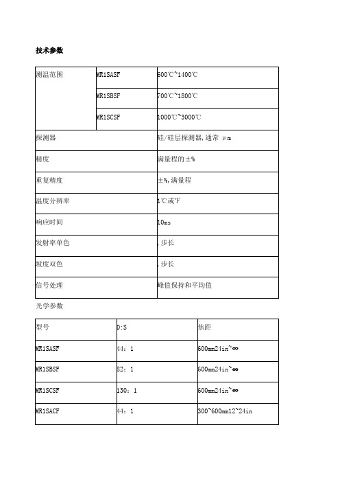
技术参数光学参数95%能量时,CF=近焦,SF=标准焦距最小焦距时的最小光点尺寸最小的光点尺寸直径=最小焦距/最小的D:S 一般参数电气参数仪器特点Marathon FA红外测温仪技术参数:1、温度测量范围: 250℃到 3000℃482°F to 5432°F2、光学分辨率最高可达 100:13、特别适用于现场安装空间狭小的安装条件4、精度高,测量值的± %5、更快速响应时间 10 毫秒,可选到10秒6、提供模拟量和数字量输出技术参数Marathon FA 红外测温仪介绍雷泰马拉松 FA 系列红外测温仪使用光纤技术可克服测量过程中各种极端的环境条件;FA 系列红外测温仪由电子盒和光纤探头、光缆组成,探测器和信号处理部分集成在一电子盒中,此电子盒可远距离放置,光纤探头和光缆可安装在强电磁场中的环境中,并且可耐的最高环温达200℃;雷泰马拉松FA 系列光纤测温仪的测温范围为250℃到3000℃482°F to 5432°F ,FA 光纤探头由耐用光缆将光学探头连接到电路盒上,电路盒包括:探测器、电子线路、内置用户接口、LED 显示及连接电缆的接线端子;FA1 和FA2 系列尤其适用于目标不能接近的、恶劣的工业环境,安装空间狭小的现场测温应用;雷泰 FA 系列单色光纤式测温仪的固定焦距的光学探头包括一个小的不锈钢圆柱形外壳和透镜,其可承受的环境温度高达200℃ ,并且符合NEMA-4的标准;雷泰 FA 系列的光纤探头可装一空气吹扫器以防止透镜被污染,光缆由金属套保护,并由VITON 保护套所密封,以防止水和油的流入,这种装配可使光缆以很小的半径弯曲以便其方便地穿过狭小的空间;雷泰 FA 系列单色光纤式测温仪还提供可在PC 上使用的WINDOWS下的马拉松软件,以实现远程进行参数设置、数据读取、数据的图形显示及RS485的多点网络配置;雷泰 FA 系列单色光纤式测温仪主要应用于以下行业:1、冶金及金属加工、热处理2、玻璃加工3、半导体加工等仪器特点Marathon FR红外测温仪技术参数:1、测温范围: 500°C 到2500°C 932°Fto 4532°F2、光学分辨率最高可达 60:13、使用光纤技术克服测量过程中的各种极端环境条件4、独特的"脏镜头"报警功能5、光缆可在现场更换,无需用黑体标定;马拉松FR1光纤双色测温仪测温范围为500~2500°C;这种测温仪可测量处于十分恶劣的工业环境中的目标,包括难以接近的,处于高温的以及靠近强磁场的目标;小巧焦距可选的光学头,由柔软可变形的光纤将其连接到安装在远处的电子盒上;Marathon FR红外测温仪特点:1、光缆可现场更换2、光缆组装系统可承受200°C 392°F高温,密封等级NEMA-43、粗糙的光缆可防水或油4、小于38mm 英寸的光缆弯曲半径5、高光学分辨率>60:1可测小目标6、单色或双色工作方式可选独有性能7、可聚焦的光学头8、快速响应时间可达10毫秒9、双向RS-485通讯可组成多头网络10、一个多点网络支达持多32个马拉松传感头11、同时模拟和数字输出并带用户报警设定12、独有的不洁窗口报警功能13、马拉松软件可遥控设置和监测14、现场标定和传感头诊断软件技术参数测量参数光学参数90%能量时,CF=近焦,SF=标准焦距可选激光瞄准电气参数产品详情雷泰MM在线式红外测温仪1、高光学分辨率,最高可达70:12、实时背景环境温度补偿、3、简单易用的操作界面4、光学和激光或视频瞄准方式5、坚固的不锈钢外壳6、模拟量和数字同步输出7、现场标定软件8、Windows操作系统下的datatemp多探头操作软件可以显示和分析测量到的数据9、传感头可以很容易的设置为标准单头运行模式,所有的MARATHOR MM系列探头又具有易于对准目标的光学瞄准和激光瞄准方式,MARATHON MM 还具有可选的视频瞄准方式;MARATHON系列测温仪包括双向485串口通讯能在工厂现场的单个探头或多探头测量网络与中控室的计算机之间进行通讯,这使得能对探头进行远程设置,监视,标定与维护,特别适合将探头安装在不易接近目标的位置;技术参数① 2ML型精度为±读数的%+2℃下②精度在环温23℃±5℃73°F± 9°F③在聚焦点处的光学系数电气性能概述环境参数概述更宽的测温范围:1、-40°C 到3000°C-40°F到5432°F2、光学分辨率最高可达 300:13、提供精确可变焦镜头4、可选择彩色视频瞄准模式5、配备光学瞄准和激光瞄准模式6、坚固的不锈钢外壳7、简单易用的操作界面8、实时视频监控和记录功能9、集单镜头反光式取景器TTL和视频或激光瞄准等多种观察方式于一身新型 Marathon MM 系列平台,温度测量范围为 -40℃ ~ 3000℃-40℉ ~ 5432℉,由 6 种红外线IR温度传感器组成,每一种传感器都可以测量一定范围的波长,并分别可以测量低温-40℃~800℃/-40℉~1472℉、中温250℃~1100℃/482℉~2012℉,或者高温300℃~3000℃/572℉~3273℉等温度范围的物体; 所有传感器均采用相同的安装硬件和雷泰RaytekDataTemp Multidrop 软件,安装、组态和数据采集方便、准确,用途广泛:1、钢铁和金属加工锻造和热处理2、新MM3M特别适用于低发射率的物体如铜、铝的金属加工3、玻璃热弯、成型、回火、退火,以及密封4、纸加工行业油墨干燥/固化和成型5、塑料加工和热力塑型;以及半导体加工等6、为满足多种行业的需求并扩大产品的应用范围,雷泰提供有六种 MM 传感器:型号温度范围光谱响应响应时间95% 响应LT-40°C - 800°C-40°F - 1472°F8 - 14 μm120 ms G5L250°C - 1650°C482°F - 3002°F5 μm60 ms450°C - 2250°CG5H5 μm60 ms232°F - 1322°F250°C - 1100°Cμm120 ms MT482°F - 2012°F100°C - 600°Cμm 2 ms 3ML212°F - 1112°F300°C - 1100°C2MLμm 2 ms572°F - 2012°F350°C - 2250°Cμm 2 ms 2MH852°F - 4082°F450°C - 1740°C1ML1 μm2 ms842°F - 2732°F650°C - 3000°C1 μm2 ms1MH1202°F - 5432°F特点:1、IP65 密封标准,可以防止安装、设置和使用过程中的污染和损伤2、标准模拟量、数字量和分布式继电器输出,可以同时传输数据、报警触发和控制信号3、内置 RS485 接口,可以以多分支multi-drop连接方式连接多达 32 个传感器4、使用雷泰软件,通过一台 PC,即可以进行远程监控、传感器控制,以及数据采集5、实时视频监控和记录功能6、更宽的温度测量范围: -40 ~ 3000℃/-40 ~ 5432℉7、集单镜头反光式取景器TTL和视频或激光瞄准等多种观察方式于一身8、高达 300:1 的高分辨率光学系统9、不锈钢外壳10、操作界面简单易用产品详情仪器特点XR系列为工业生产过程的工业控制提供持续的温度监测,秉承雷泰产品坚固、耐用的风格,其一体化的产品设计将可以帮助你在更多的应用环境下进行温度测量;雷泰XR系列特别适用较小目标或是使用较长瞄准管的温度测量,此外,直观的内置用户操作界面大大减少了产品设置时间,并且增加了强大的现场问题处理能力;雷泰XR系列使用最通用的安装配件和软件,极大降低了设备安装和调整的成本,可被安装在任何已经存在或运行的系统中,为生产过程提供持续的温度监测,从而精确控制温度变化,帮助客户降低能源损耗;性能亮点:1、提供多种温度的测量范围2、内置电子操作面板3、提供数字和模拟量输出4、高光学分辨率5、符合NEMA-4密封标准技术参数可选附件产品描述:雷泰 XR 系列为工业生产过程的工艺控制提供持续的温度监测;XR 系列秉承雷泰产品坚固、耐用的风格,符合 NEMA-4 密封标准,其一体化的产品设计将可以帮助您在更多的应用环境下进行温度测量;雷泰XR 系列提供多种温度的测量范围,高光学分辨率, RS485数字输出,简单易于使用的电子操作面板可以帮助您解决工业生产中所遇到的测温难点;具备激光瞄准方式可选和高光学分辨率的雷泰 XR 系列特别适用于较小目标或是使用较长的瞄准管的温度测量;此外,直观的用户操作界面大大减少了产品设置时间并且增加了强大的问题处理能力;雷泰XR 系列使用最通用的安装配件和软件,极大降低了设备安装和调整的成本;此外,雷泰XR 系列可提供模拟量输出,这种方式使 XR 系列可被安装在任何已经存在或运行的系统中;雷泰 XR 系列为生产过程提供持续的温度监测,从而精确控制温度变化,帮助客户降低能源消耗;响应波长光学分辨率型号温度范围-40°C到600°CLT 低温型8到14 μm33:1-40°F to 1112°F-40°C到600°CLTHSF 低温型8到14 μm50:1-40°F to 1112°F250°C到1200°CMT 中温型μm30:1482°F to 2190°F250°C到1650°Cμm33:1 G5 玻璃专用型482°F to 3002°F10°C到360 °CP7 塑料专用型μm30:150°F to 680 °F产品详情仪器特点TX/SX系列集成式传感头提供精确的温度测量从适于多变的过程控制应用,通过双通道的数字通道;1、简单的双线安装2、坚实耐用的传感头符合IP65NEMA4标准3、款温度范围:-18~2000度4、在单一多头网络上安装可多达15个传感头5、Windows下软件以远程探头设置和监测6、通过透镜或激光瞄准7、4-20mA和数字同时输出8、信号处理9、焦距多种可选10、玻璃和塑料的特殊型号TX系列红外测温仪集高性能的非接触温度测量和标准二线技术于一体;用户可选择基本型或智能型;LT:印刷、造纸、层压、干燥/加工、食品、纺织、制药MT:冶金、窑炉、平板玻璃、耐火材料、加热炉HT:感应加热、加热炉、金属冶炼G5:玻璃表面测量如回火、退火、热成型、封接、弯曲等P7:氟塑料、特氟龙、丙烯酸、尼龙、聚乙烯、聚氯乙烯薄膜和复合材料的生产技术参数可选附件1、瞄准镜2、空气吹扫器3、NIST/DKD标定证书4、空气/冷却套可选5、直角反射镜6、热保护套7、℃/℉适用于基本型8、本证安全型表示订货时必须说明Thermalert TX红外线温度传感头现有两种配置可选:1. TX基本型传感头单探头使用时提供优良性能.2. TX智能型传感头, 具有远程寻址功能,可以方便安装在多点网络上如监测玻璃和塑料的工艺生产线;TX系列智能型传感头在简单的二线回路上采用HART通讯协议进行通讯;输出信号同时包括工业标准的4-20mA和数字信号;Thermalert TX一般性能指标:1、简单的二线安装2、温度范围宽,从-18° 到2000°C -0° to 3600°F3、对于TX智能型传感头可同时有4-20 mA和数字输出4、耐用的传感头符合NEMA-4 IP 65标准5、先进的信号处理6、点对点或者多点安装最多安装15个传感头7、Windows操作系统软件,可进行远程设置和显示8、多种焦距范围可选9、有玻璃和塑料的专用型号10、DataTemp TX软件专门为PC机上的运行而编写的DataTemp TX软件大大简化了Thermalert TX的操作;DataTemp TX软件允许你设定温度和输出范围、发射率、报警点,而且在实时图形显示上,可以从一个点或者多个传感头监测温度数据;你可以记录和保存这些数据并导入总分析表和数据库程序;程序还有下拉菜单、友好用户界面,外加在线提示信息和帮助;产品详情仪器特点雷泰在线红外测温仪中国一级代理提供Raytek MI3 红外测温仪报价咨询,欢迎选购;Raytek MI3是一款功能强大的分体式红外线温度测量系统,具有微型传感头和独立的通讯电子盒;该传感器体积小巧,几乎可安装于任何地方,其性能却远远优于大型系统;Raytek MI3是一款功能强大的分体式红外线温度测量系统,具有微型传感头和独立的通讯电子盒;该传感器体积小巧,几乎可安装于任何地方,其性能却远远优于大型系统;同时具有坚固的金属铸造电子盒外壳,创新的DIN安装的多通道连接盒或低廉的OEM配置供选择;MI3提供其它昂贵的传感器所不具备的大量高级信号处理功能;为OEM设计的MI3可以直接和主机控制器进行数字通信而无需另外的通信盒;创新的8个传感头设计,可独立寻址,降低红外测温成本,简化测温设置和方案实施的故障率,并且测量点成本更为低廉;MI3 也可实现在封装测试中实现USB和RS485数字通信;技术参数应用:工业OEM;印刷,纸业,纺织,锻造, 干燥和固化;沥青和建筑材料;制塑,热成形,制模,焊接,密封;固化烘箱和工业干燥箱;食品加工,制药业;设备检测与保养;导线和开关检测 ;电气技电气技术指标MI3COMM电气技术指标MI3MCOMM感应头技术指标产品详情仪器特点雷泰GP红外测温仪产品特点:1、温度范围是从-18 到538°C 0 到1000°F2、最新GPS激光瞄准头3、耐用的1/8 DIN 数字显示表,4位数字大窗口4、监视器和传感器功能设置位于前面板5、具有许多只有在大系统上才有的数据处理能力6、发射率和环温参数可调7、全球统一的110-220 V交流电源8、用户设置的4-20 mA或者热电偶输出J, K, E, N, R, S, T9、可调的双设置点和死区报警输出10、根据不同应用,可接多种探头11、标准或近焦距可选12、冷却和空气吹扫附件13现场可更换探头技术参数测量参数电参数探头参数产品详情仪器特点raytek 在线红外测温仪中国一级代理提供raytek cm在线红外测温仪报价咨询,欢迎选购;雷泰新一代CM 高性能迷你型红外测温仪, 专为工业设备用户的多种应用需求选择. CM红外测温仪温度范围广、精度高、体积小、多种输出模式、性价比高,是系统集成商、设备配套Raytek CM红外线测温仪特点:OEM用户的最佳选择1、测温范围: -20 ~ 500 ℃ -4 to 932°F2、光学分辨率: 13:13、响应时间:150 毫秒4、机身为不锈刚外壳,密封等级: NEMA-4X, IP655、输出:0-5 V 输出, J 型或K型输出, RS232, 报警输出6、LED 探头故障自检功能7、RS232 数字通讯,可远程控制、设置探头参数8、信号处理可调9、WINDOWS 下DataTemp 多探头专用温度监控软件10、多种附件可选:空气吹扫器及镜头保护附件技术参数性能描述:雷泰新一代CM 高性能迷你型红外测温仪, 专为工业设备用户的多种应用需求选择. CM红外测温仪温度范围广、精度高、体积小、多种输出模式、性价比高,是系统集成商、设备配套商的最佳选择;C M探头自带J型或K型热偶输出,可以很容易地替代设备中已使用的传统热偶, 此外,CM还提供0-5伏的输出方式;CM 新一代迷你型红外测温仪采用不锈钢机身,仪器的密封等级达到“IP 65 NEMA-4 ”,使得CM探头在即使没有水冷套的情况下,依然可以在最高70°C 160°F 的环境温度下正常工作;CM新一代红外测温仪是目前市场上同类产品中,功能最强大的一款小尺寸产品; CM 的RS232 数字通讯接口、专用的WINDOWS下操作软件为操作者远程设置参数、探头远程监控可同时监控多个探头提供极大的方便; 此外,CM 还内置LED 故障指示灯,当探头在非常状态下时,该指示灯会提示不同灯光信号提示,用户可根据操作手册的上面的灯光指示对应的状态来实时了解仪器的工作状态;电参数物理性能产品详情仪器特点雷泰MID系列红外测温仪由很小的传感头和电路盒组成,电路盒内置LCD温度显示和设置按键,具有多种信号处理功能和输出方式,还具有环温补偿、报警、传感头可换等特点;技术参数美国RAYTEK MID系列在线式产品介绍:雷泰MID系列红外测温仪由很小的传感头和电路盒组成,电路盒内置LCD温度显示和设置按键,具有多种信号处理功能和输出方式,还具有环温补偿、报警、传感头可换等特点;主要应用:OEM、塑料、造纸、印刷、铁路、烟草、食品加工及包装机械等;美国雷泰RAYTEK MID系列在线式红外测温仪主要特性1、输出:4~20mA,0~20mA,0~5V 三种标准信号 J 或 K 型热偶,10mV/℃传感头环温信号,2、RS232/RS485可选3、光谱响应:LT/G5/MTP:8~14μm/5μm/~4μm4、响应时间:150ms5、重复性:±1% 或±1 ℃,取最大值6、发射率可调:~,步长7、尺寸:传感头:28 x 14mm;8、电路盒:80 x 60 x 25mm9、重量:传感头带1m 电缆50g;电路盒270g10、美国雷泰RAYTEK MID系列在线式红外测温仪技术参数:。
卡西欧电子表电池型号大全

AW-582 电池----CR1220AW-590 电池----CR1220 机芯-----4778AW-591 电池----CR1220 机芯-----4778AWG-100 电池----光动能--CTL1616-----4765AWG-101 电池----光动能--CTL1616-----4765DW-5600C 电池----CR2016 机芯-----691 / 901DW-5600E 电池----CR2016 机芯-----1545DW-56RT 电池----CR2016 机芯-----2991DW-56RTB 电池----CR2016 机芯-----2991DW-6600 电池----CR2016 机芯-----1199DW-6900 电池----CR2016 机芯-----1289DW-9052 电池----CR2016 机芯-----1659G-011 电池----CR1220 机芯-----4762G-1000 电池----SR927W 机芯-----5034G-1700 电池----CR1220 机芯-----4731G-1710 电池----CR1220 机芯-----4737G-1800 电池----CR1220G-2300 电池----光动能-----ML2016-----2184G-2500 电池----CR1616 机芯-----2266G-304 电池----SR927W x 2 机芯-----4367G-314 电池----SR927W x 2 机芯-----4367G-540 电池----SR927W x 2 机芯-----4314G-7100 电池----CR2025 机芯-----2821G-7600 电池----CR2016 机芯-----G-7710 电池----CR2025 机芯-----3095G-9000 电池----CR2025 机芯-----3031G-9100 电池----CR2025 机芯-----GS-1000 电池----光动能-----CTL102 机芯-----4343GS-1100 电池----光动能-----CTL1025 机芯-----4777 GW-002 电池----光动能--CTL1616 机芯-----2913GW-1200 电池----光动能-----CTL1025 x 2 机芯-----3335 GW-1500 电池----光动能--CTL1616 机芯-----3366GW-5600 电池----光动能--CTL1616 机芯-----2924GW-5600BCJ 电池----光动能--CTL1616 机芯-----2924 GW-600 电池----光动能--CTL1616 机芯-----2971GW-700 电池----光动能--CTL1616 机芯-----2818GW-800 电池----光动能--CTL1616 机芯-----3061GW-800D 电池----光动能--CTL1616 机芯-----3061GW-810 电池----光动能--CTL1616 机芯-----3050MTG-1000 电池----光动能-----CTL1025 机芯-----5022 PAW-1500 电池----光动能--CTL1616 机芯-----3134 PAW-1500T 电池----光动能--CTL1616 机芯-----3134 PRG-40 电池----SR927Wx4 机芯-----2271PRG-80 电池----光动能--CTL1616PRG-80T 电池----光动能--CTL1616DW-5000C-1A 机芯型号---240 年代---1983 电池型号---BR-2320DW-5000C-1B 机芯型号---240 年代---1983 电池型号---BR-2320WW-5100C-1 机芯型号---491 年代---1983 电池型号---BR-2320WW-5100C-9 机芯型号---491 年代---1983 电池型号---BR-2320DW-5200C-1 机芯型号---240 年代---1984 电池型号---BR-2320DW-5200C-9 机芯型号---240 年代---1984 电池型号---BR-2320WW-5300C-1 机芯型号---491 年代---1984 电池型号---BR-2320DW-5400C-1 机芯型号---240 年代---1985 电池型号---BR-2320DW-5400C-9 机芯型号---240 年代---1985 电池型号---BR-2320DW-5500C-1 机芯型号---240 年代---1985 电池型号---BR-2320DW-5600C-1 机芯型号---691 年代---1987 电池型号---CR-2320DW-5600C-1V 机芯型号---691 年代---1987 电池型号---CR-2320DW-5600C-9V 机芯型号---691 年代---1987 电池型号---CR-2320DW-5600C-9CV 机芯型号---691 年代---1990 电池型号---CR-2320DW-5600C-9BV 机芯型号---691 年代---1989 电池型号---CR-2320DW-5600C-9B 机芯型号---901 年代---1992 电池型号---CR-2016DW-5600D-1 机芯型号---901 年代---1992 电池型号---CR-2016DW-5600B-2V 机芯型号---901 年代---1991 电池型号---CR-2016DW-5600B-3V 机芯型号---901 年代---1991 电池型号---CR-2016DW-5700C-1V 机芯型号---691 年代---1987 电池型号---CR-2320DW-5700C-9V 机芯型号---691 年代---1987 电池型号---CR-2320DW-5700C-9GV 机芯型号---691 年代---1987 电池型号---CR-2320DW-5800C-1V 机芯型号---691 年代---1987 电池型号---CR-2320DW-1983-1 机芯型号---901 年代---1993 电池型号---CR-2016大家可以用搜索功能找自己的资料,另外,如果这里没有的型号,请按照机芯数据查找,只要知道自己表的机芯就知道用什么电池了,如下表所示。
futaba6EXHP原厂中文使用说明书
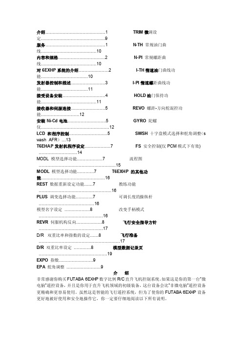
介绍..........................................1TRIM微调设定 (9)服务..........................................1N-TH常规油门曲线 (10)内容和规格.................................2N-PI常规螺距曲线 (10)对6EXHP系统的介绍…………………2I-TH惰速油门曲线功能 (10)发射器控制和描述……………………3I-PI惰速螺距曲线功能 (11)接受设备安装…………………………4HOLD油门保持功能 (11)接收器和伺服连接........................5REVO螺距-方向舵混控功能 (12)安装Ni-Cd电池...........................5GYRO陀螺仪 (12)LCD 和程序控制...........................5SWSH十字盘模式选择和舵角调整(s washAFR) (13)T6EHAP发射机程序设定..................7FS安全控制(仅PCM模式下有效) (14)MODL 模型选择功能..................7流程图 (15)MODL模型选择功能…………7 T6EXHP的其他功能 (16)REST数据重新设定功能......7教练功能 (16)PLUS调变选择功能............7可调长度的操纵杆 (16)模型名字设定..................8改变手柄模式 (16)REVR伺服机构反向..................8飞行安全指导方针 (17)D/R 双重比率和指数的设定......8飞行准备 (17)D/R双重比率设定............8模型数据记录页 (19)EXPO指数 (9)EPA舵角调整 (9)介绍非常感谢你购买FUTA BA 6EXHP数字比例R/C直升飞机控制系统。
轻触开关,按键开关图纸
30,000 cycles-----260gf,520gf
CTSL(f)-6
Size: Total Height: Operating Force: gf,520gf Stroke: Life: 160gf 20gf,520gf
6.2mm*6.4mm 2.0mm,2.5mm 100gf,160gf,260gf,320
TA(S)-6
Size:
Stem Height: 35mm Operating Force:
Stroke: m Life: f, 260gf
6.1mm*7mm 0mm,0.8mm,1.0mm,2.
180gf,260gf 0.45+0.20/-0.20m 500,000 cycles-----180g
5˚+2.5˚/1.5˚----------0.25+0.10/-0.20mm-----
產品結構
• 正向式觸動開關 • 側向式觸動開關 • 複合式觸動開關
正向式觸動開關
Stem Cover Contact Disc Base Terminal
側向式觸動開關
Stem Cover Tape Contact Disc Base Terminal
CTSM-6(2)
Size:
6*6 ----- 6.2mm*6.2mm
12*12 ----- 12mm*12mm
Total Height:
4.3mm,5.0mm,7.0mm,7.3mm,9.5mm,13.0mm----DTSM-6
4.3mm,7.3mm,8.5mm----------------------------------DTSM-2
• 一般機構設計上不會做死點設計 • 設計於推柄為軟性材質上
H160A中文资料
25.00 MHz TO 31.9MHz 32.00 MHz TO 70.00 MHz
.110
1.5 ± 0.1 DIA .059 ± .004 DIA
2.0 ±ቤተ መጻሕፍቲ ባይዱ0.1 .079 ± .004
16 ± 0.3 .630 ± .012
260 °C 255 °C TEMPERATURE 217°C 200°C 150°C +3°C/s MAX PREHEATING 25 °C
8.4 ±0.10 .331±.004
PEAK - 10 SECONDS MAX
.295 ± .004
SOLDER REFLOW PROFILE
4.0 ± 0.1 .157 ± .004
7.5 ± 0.1
1.75 ± 0.1 .069 ± .004
1.5 .06
.110
2.8
2.0
.08
2.8
CARRIER TAPE DIMENSIONS
元器件交易网
SURFACE MOUNT MICROPROCESSOR CRYSTAL
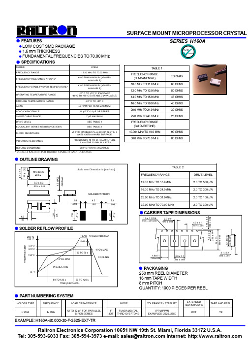
FEATURES LOW COST SMD PACKAGE 1.6 mm THICKNESS FUNDAMENTAL FREQUENCIES TO 70.00 MHz SPECIFICATIONS
EXTENDED TEMPERATURE (PPM/PPM) EXAMPLES: 2525, 2550 EXT TR
PART NUMBERING SYSTEM
HOLDER TYPE H160A IN MHz FREQUENCY 12 TO 32 pF FOR PARALLEL S FOR SERIES LOAD CAPACITANCE F 3OT FUNDAMENTAL THIRD OVERTONE MODE TOLERANCE / STABILITY TAPE AND REEL
FSA66M5X中文资料
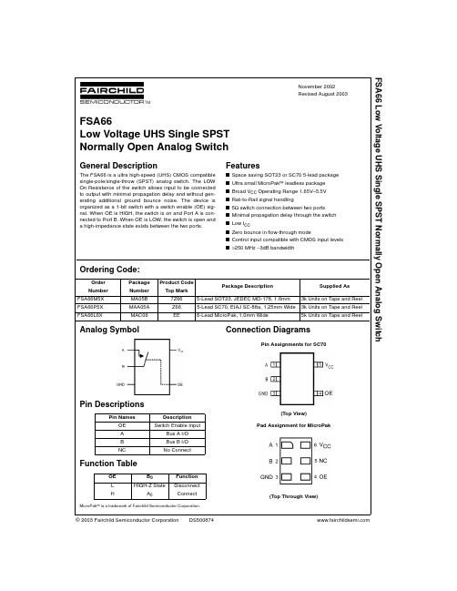
The FSA66 is a ultra high-speed (UHS) CMOS compatible single-pole/single-throw (SPST) analog switch. The LOW On Resistance of the switch allows input to be connected to output with minimal propagation delay and without generating additional ground bounce noise. The device is organized as a 1-bit switch with a switch enable (OE) signal. When OE is HIGH, the switch is on and Port A is connected to Port B. When OE is LOW, the switch is open and a high-impedance state exists between the two ports.
−0.5V to +7.0V −0.5V to VCC +0.5V −0.5V to +7.0V −50 mA
128 mA
Recommended Operating Conditions (Note 3)
Power Supply Operating (VCC) Control Input Voltage (VIN) Switch Input Voltage (VIN) Switch Output Voltage (VOUT) Input Rise and Fall Time (tr, tf) Control Input; VCC = 2.3V−3.6V Control Input; VCC = 4.5−5.5V Switch I/O Operating Temperature (TA) Thermal Resistance (θJA) SOT23-5 300°C/Watt 425°C/Watt SC70-5 0 ns/V to 10 ns 0 ns/V to 5 ns 0 ns/V to DC 1.65V to 5.5V 0V to 5.5V 0V to VCC 0V to VCC
HID618A伺服驱动器
HID618 系列液压伺服专用驱动器
目录 CONTENTS
HID618 系列伺服驱动器
1
功能特点
2
应用领域
4
技术参数
6
产品命名
7
产品选型
7
规格型号
8
产品外型图
8
HM 系列伺服电机
9
产品特点
9
产品命名
9
规格参数
10
传感器接线说明
11
接线注意事项
11
HID618 系列伺服驱动器
液压系统控制示意图
公司针对客户的不同需求,特别设计 HID619 异步伺服专用驱动器,主要适用于三相交流异步电机或者变频电机拖 动的液压设备。该产品内部集成电流转电压转换板,直接采样比例流量阀、比例压力阀的电流信号控制系统油泵电机的转速; 其无需更换异步电机,不必改变系统自身油路,改造更方便快捷。
传统定量泵注塑机电机转速不可调,输入功率不变,通过阀门调节改变系统流量和压力。改造后驱动器可根据控制指 令调节电机转速,在满足成型要求的前提下,改变油泵输出液压油流量,减少液压油从溢流阀会流油箱的损耗,节省了大 量电能。
1 组 CAN 通讯端子,可实现多台驱动器间的高速 CAN 总线通讯,控制多台泵的合流和分流 1 组 485 通讯端子
过压保护、欠压保护、过流保护、模块保护、散热器过热保护、电机过载保护、外部故障保护、电流检测异常、 输入电源异常、输出缺相异常、EEPROM 异常、继电器吸合异常
IP20 垂直安装在良好通风的电控柜内,无尘、无腐蚀性气体、无可燃性气体、无油雾、无蒸汽、无滴水的环境, 不受阳光直晒 -10℃ ~+40℃(环境温度高于 40℃,请降额使用,每升高 1℃,额定输出电流减少 1%) 0~2000 米,1000 米以上降额使用,每升高 100 米,额定输出电流减少 1% 20%~90%RH(无凝露) 小于 5 米 / 平方秒(0.5g) -25℃ ~+65℃
无线发射氧化锌避雷器测试仪说明书

无线发射氧化锌避雷器带电测试仪无线发射氧化锌避雷器带电测试仪是用于检测氧化锌避雷器电气性能的专用仪器,该仪器适用于各种电压等级的氧化锌避雷器的带电或停电检测,从而及时发现设备内部绝缘受潮及阀片老化等危险缺陷。
仪器操作简单、使用方便,测量全过程由单片机控制,可测量氧化锌避雷器的全电流、阻性电流及其谐波、工频参考电压及其谐波、有功功率和相位差,大屏幕可显示电压和电流的真实波形。
仪器运用数字波形分析技术,采用谐波分析和数字滤波等软件抗干扰方法使测量结果准确、稳定,可准确分析出基波和3~7次谐波的含量,并能克服相间干扰影响,正确测量边相避雷器的阻性电流。
本机配有高速面板式打印机,可充电电池,试验人员在现场使用十分方便。
仪器采用独特的高速磁隔离数字传感器直接采集输入的电压、电流信号,保证了数据的可靠性和安全性。
一、仪器特点1)本机采用大屏幕液晶显示,全中文菜单操作,使用简便。
2)高精度采样、处理电路,先进的付里叶谐波分析技术,确保数据更加可靠。
3)仪器采用独特的高速磁隔离数字传感器直接采集输入的电压、电流信号,保证了数据的可靠性和安全性。
4)本仪器可以使用电场感应的方法代替PT二次接线。
5)本仪器可以不接PT二,直接测量阻性电流。
6)本仪器可以三相同测,自动补偿。
使用特别方便7)具有阻性电流基波峰值输出、边相校正等功能。
8)仪器配有可充电电池、日历时钟、微型打印机,可存储120组测量数据;二、仪器面板示意图1 8234 9567 10图一面板说明:1---参考电压输入端;2---天线;3---测量接地端;4---微型打印机;5---电源开关;6---充电插座;7---串口;8---泄漏电流输入端;9---液晶显示器;10—触摸键盘主要技术参数全电流测量范围:0~10mA有效值准确度:±(读数×5%+5uA)阻性电流基波测量准确度(有线不含相间干扰):±(读数×5%+5uA)* 电流谐波测量准确度:±(读数×10%+10uA)电流通道输入电阻:≤2Ω参考电压输入范围:25V~250V有效值准确度:±(读数×5%+0.5V)电压谐波测量准确度:±(读数×10%)参考电压通道输入电阻:≥1800kΩ电场强度输入范围:30kV/m~300kV/m电场强度测量准确度:±(读数×10%)电场谐波测量准确度:±(读数×10%)交流充电:AC 220V 10%,50Hz 1%电池连续工作时间:8小时以上电池充电时间:6小时以上仪器尺寸:34cm×22cm×20cm仪器重量:5kg(不含电缆箱)三、操作模式1.(PT二次)模式,(PT二次同步显示)模式:仪器输入PT二次电压作为参考信号,同时输入MOA电流信号,经过傅立叶变换可以得到电压基波U1、电流基波峰值Ix1p和电流电压角度Φ。
618NN;中文规格书,Datasheet资料
ml = max. load · me = max. efficiency · fa = running at free air · cs = customer specs · cu = customer unit Subject to alterations
Web data sheet XI · Page 1 of 4 ebm-papst St. Georgen GmbH & Co. KG · Hermann-Papst-Straße 1 · D-78112 St. Georgen · Phone +49 7724 81-0 · Fax +49 7724 81-1309 · info2@ ·
618 NN
DC axial compact fan
ebm-papst St. Georgen GmbH & Co. KG Hermann-Papst-Straße 1 D-78112 St. Georgen Phone +49 7724 81-0 Fax +49 7724 81-1309 info2@
Mass Dimensions Material of impeller Housing material Direction of air flow Direction of rotation Bearing Lifetime L10 at 40 °C Lifetime L10 at maximum temperature Connection line Motor protection Locked-rotor protection Approval
/
618 NN
DC axial compact fan
Charts: Air flow
CW6185(天水机床)

CWA6185×5000mm卧式车床技术说明一、机床总体介绍CWA6185卧式车床是我厂系列产品之一,它具有精度高、功率大、刚性高、制造精良、功能齐全等特点。
该系列产品是我厂依据CW61100E系列产品成熟技术的基础上,充分研究国内外现有卧式车床的不同特点,重新开发的新产品系列。
其主要部件和结构均经过优化设计,现经多家用户使用验证,该产品在同类产品中具有明显的优势,其高精度、高效率、高可靠性等特点受到了用户的好评,其全新的主传动变频调速系统的应用,不仅得到用户的高度青睐,而且在同行业也是首屈一指,现已批量生产。
二、主要技术参数床身上最大回转直径Φ850 mm 顶尖间最大工件长度5000 mm 刀架上最大回转直径Φ520 mm 顶尖间工件最大重量4000 kg 主轴端部ISO(GB) A2-11 主轴通孔直径100 mm 主轴前端锥孔公制NO.120 主轴转速四档无级5~630 r/min 纵向进给量64种0.08~9.6 mm 横向进给量64种0.04~4.8 mm 上刀架进给量64种0.02~2.4 mm 公制螺纹56种1~120 mm 英制螺纹56种30~9/8 t.p.i.模数螺纹56种0.5~60 mm 径节螺纹56种60~0.5 D.P 刀架回转角度±90°刀杆截面尺寸32×32 mm 刀架最大切削力45 KN 刀架最大横向行程600 mm 上刀架最大行程250 mm 刀架快速移动纵向3640 mm/min横向1800 mm/min上刀架900 mm/min 尾座套筒直径Φ120 mm 尾座套筒锥孔莫氏6号尾座套筒最大行程250 mm 主电机功率AC 15 kw 快速电机功率 1.1 kw 油泵电机功率0.55 kw 冷却电机功率0.15 kw三、机床各主要部件介绍1)、床身床身采用整体结构,树脂沙造型,导轨采用中频淬火磨削工艺,使用导轨硬度达到HS65°。
XL6006 180KHz 60V 5A开关电流升压型LED恒流驱动器说明书
180KHz 60V 5A 开关电流升压型LED恒流驱动器XL6006特点⏹5V到32V宽输入电压范围⏹输出电压最高可升压至60V⏹0.22V输出电流采样电压⏹输入电压24V,输出可驱动16串1W/3WLED灯⏹固定180KHz开关频率⏹最大5A开关电流⏹94%以上转换效率⏹出色的线性与负载调整率⏹EN脚TTL关机功能⏹内置功率MOS⏹内置软启动功能⏹内置频率补偿功能⏹内置热关断功能⏹内置限流功能⏹TO263-5L封装应用⏹通用LED照明⏹升压恒流驱动⏹显示器LED背光描述XL6006是一款升压恒流型LED驱动器,具有出色的线性调整率与负载调整率,可以驱动1W/3W/5W的LED灯。
XL6006内置固定频率振荡器与频率补偿电路,简化了电路设计。
当输入电压等于24V时,XL6006可驱动16串1W/3W LED。
PWM控制环路可以调节占空比从0~90%之间线性变化。
内置使能功能、过电流保护功能。
内部补偿模块可以减少外围元器件数量。
图1.XL6006封装180KHz 60V 5A 开关电流升压型LED 恒流驱动器 XL6006引脚配置FB SW EN GNDVIN 12345TO263-5L图2. XL6006引脚配置表1.引脚说明引脚号 引脚名称 描述1 GND 接地引脚。
2 EN 使能引脚,低电平关机,高电平工作,悬空时为高电平。
3 SW 功率开关输出引脚,SW 是输出功率的开关节点。
4 VIN 电源输入引脚,支持DC5V~32V 宽范围电压操作,需要在VIN 与GND 之间并联电解电容以消除噪声。
5 FB反馈引脚,参考电压为0.22V 。
180KHz 60V 5A 开关电流升压型LED 恒流驱动器 XL6006方框图NDMOSVINSWGNDFB2.5V 0.22VCOMP2.5V Regulator 0.22V ReferencePhase CompensationRS LatchUVLOSoft StartThermal ShutdownEAEA ∑Driver OCPOVPENOscillator180KHzSlop Compensation图3. XL6006方框图典型应用XL6006CIN 47uF 35VL1 47uh/5AVIN41253GNDVINSWFBENONOFFI LED =0.22/RSD1 SS38RS 350mASeries 16 1W LEDC1 105COUT 100uF 63VC2 105图4. XL6006典型应用电路180KHz 60V 5A开关电流升压型LED恒流驱动器XL6006订购信息产品型号打印名称封装方式环保认证包装类型XL6006E1 XL6006E1 TO263-5L RoHS & HF 800只每卷绝对最大额定值(注1)参数符号值单位输入电压Vin -0.3到36 V-0.3到Vin V 反馈引脚电压VFB使能引脚电压V-0.3到Vin VEN-0.3到60 V 输出开关引脚电压VSW内部限制mW 功耗PD热阻(TO263-5L)R JA30 o C /W (结到环境,无外部散热片)操作结温T-40到125 o CJ-65到150 o C 贮存温度范围TSTG引脚温度(焊接10秒) T260 o CLEADESD (人体模型) 2000 V 作,在绝对最大额定值条件下长时间工作可能会影响芯片的寿命。
欧洲品牌电磁组件型号X12345产品说明书
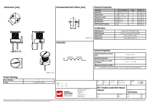
Dimensions: [mm]Scale - 2,5:17447720101A74477201017447720101T e m p e r a t u r eT T T 7447720101Cautions and Warnings:The following conditions apply to all goods within the product series of WE-TI of Würth Elektronik eiSos GmbH & Co. KG:General:•This electronic component was designed and manufactured for use in general electronic equipment.•Würth Elektronik must be asked for written approval (following the PPAP procedure) before incorporating the components into any equipment in fields such as military, aerospace, aviation, nuclear control, submarine, transportation (automotive control, train control, ship control), transportation signal, disaster prevention, medical, public information network, etc. where higher safety and reliability are especially required and/or if there is the possibility of direct damage or human injury.•Electronic components that will be used in safety-critical or high-reliability applications, should be pre-evaluated by the customer. •The component is designed and manufactured to be used within the datasheet specified values. If the usage and operation conditions specified in the datasheet are not met, the wire insulation may be damaged or dissolved.•Do not drop or impact the components, the component may be damaged.•Würth Elektronik products are qualified according to international standards, which are listed in each product reliability report. Würth Elektronik does not warrant any customer qualified product characteristics beyond Würth Elektroniks’ specifications, for its validity and sustainability over time.•The customer is responsible for the functionality of their own products. All technical specifications for standard products also apply to customer specific products.Product specific:Soldering:•The solder profile must comply with the technical product specifications. All other profiles will void the warranty.•All other soldering methods are at the customers’ own risk.Cleaning and Washing:•Washing agents used during the production to clean the customer application might damage or change the characteristics of the wire insulation, marking or plating. Washing agents may have a negative effect on the long-term functionality of the product. Potting:•If the product is potted in the costumer application, the potting material might shrink or expand during and after hardening. Shrinking could lead to an incomplete seal, allowing contaminants into the core. Expansion could damage the components. We recommend a manual inspection after potting to avoid these effects. Storage Conditions:• A storage of Würth Elektronik products for longer than 12 months is not recommended. Within other effects, the terminals may suffer degradation, resulting in bad solderability. Therefore, all products shall be used within the period of 12 months based on the day of shipment.•Do not expose the components to direct sunlight.•The storage conditions in the original packaging are defined according to DIN EN 61760-2.•The storage conditions stated in the original packaging apply to the storage time and not to the transportation time of the components. Packaging:•The packaging specifications apply only to purchase orders comprising whole packaging units. If the ordered quantity exceeds or is lower than the specified packaging unit, packaging in accordance with the packaging specifications cannot be ensured. Handling:•Violation of the technical product specifications such as exceeding the nominal rated current will void the warranty.•Applying currents with audio-frequency signals might result in audible noise due to the magnetostrictive material properties. •Due to heavy weight of the components, strong forces and high accelerations might have the effect to damage the electrical connection or to harm the circuit board and will void the warranty.•Please be aware that products provided in bulk packaging may get bent and might lead to derivations from the mechanical manufacturing tolerances mentioned in our datasheet, which is not considered to be a material defect.•The temperature rise of the component must be taken into consideration. The operating temperature is comprised of ambient temperature and temperature rise of the component.The operating temperature of the component shall not exceed the maximum temperature specified.These cautions and warnings comply with the state of the scientific and technical knowledge and are believed to be accurate and reliable.However, no responsibility is assumed for inaccuracies or incompleteness.Würth Elektronik eiSos GmbH & Co. KGEMC & Inductive SolutionsMax-Eyth-Str. 174638 WaldenburgGermanyCHECKED REVISION DATE (YYYY-MM-DD)GENERAL TOLERANCE PROJECTIONMETHODTRi001.0012019-07-17DIN ISO 2768-1mDESCRIPTIONWE-TI Radial Leaded Wire WoundInductor ORDER CODE7447720101SIZE/TYPE BUSINESS UNIT STATUS PAGEImportant NotesThe following conditions apply to all goods within the product range of Würth Elektronik eiSos GmbH & Co. KG:1. General Customer ResponsibilitySome goods within the product range of Würth Elektronik eiSos GmbH & Co. KG contain statements regarding general suitability for certain application areas. These statements about suitability are based on our knowledge and experience of typical requirements concerning the areas, serve as general guidance and cannot be estimated as binding statements about the suitability for a customer application. The responsibility for the applicability and use in a particular customer design is always solely within the authority of the customer. Due to this fact it is up to the customer to evaluate, where appropriate to investigate and decide whether the device with the specific product characteristics described in the product specification is valid and suitable for the respective customer application or not.2. Customer Responsibility related to Specific, in particular Safety-Relevant ApplicationsIt has to be clearly pointed out that the possibility of a malfunction of electronic components or failure before the end of the usual lifetime cannot be completely eliminated in the current state of the art, even if the products are operated within the range of the specifications.In certain customer applications requiring a very high level of safety and especially in customer applications in which the malfunction or failure of an electronic component could endanger human life or health it must be ensured by most advanced technological aid of suitable design of the customer application that no injury or damage is caused to third parties in the event of malfunction or failure of an electronic component. Therefore, customer is cautioned to verify that data sheets are current before placing orders. The current data sheets can be downloaded at .3. Best Care and AttentionAny product-specific notes, cautions and warnings must be strictly observed. Any disregard will result in the loss of warranty.4. Customer Support for Product SpecificationsSome products within the product range may contain substances which are subject to restrictions in certain jurisdictions in order to serve specific technical requirements. Necessary information is available on request. In this case the field sales engineer or the internal sales person in charge should be contacted who will be happy to support in this matter.5. Product R&DDue to constant product improvement product specifications may change from time to time. As a standard reporting procedure of the Product Change Notification (PCN) according to the JEDEC-Standard inform about minor and major changes. In case of further queries regarding the PCN, the field sales engineer or the internal sales person in charge should be contacted. The basic responsibility of the customer as per Section 1 and 2 remains unaffected.6. Product Life CycleDue to technical progress and economical evaluation we also reserve the right to discontinue production and delivery of products. As a standard reporting procedure of the Product Termination Notification (PTN) according to the JEDEC-Standard we will inform at an early stage about inevitable product discontinuance. According to this we cannot guarantee that all products within our product range will always be available. Therefore it needs to be verified with the field sales engineer or the internal sales person in charge about the current product availability expectancy before or when the product for application design-in disposal is considered. The approach named above does not apply in the case of individual agreements deviating from the foregoing for customer-specific products.7. Property RightsAll the rights for contractual products produced by Würth Elektronik eiSos GmbH & Co. KG on the basis of ideas, development contracts as well as models or templates that are subject to copyright, patent or commercial protection supplied to the customer will remain with Würth Elektronik eiSos GmbH & Co. KG. Würth Elektronik eiSos GmbH & Co. KG does not warrant or represent that any license, either expressed or implied, is granted under any patent right, copyright, mask work right, or other intellectual property right relating to any combination, application, or process in which Würth Elektronik eiSos GmbH & Co. KG components or services are used.8. General Terms and ConditionsUnless otherwise agreed in individual contracts, all orders are subject to the current version of the “General Terms and Conditions of Würth Elektronik eiSos Group”, last version available at .Würth Elektronik eiSos GmbH & Co. KGEMC & Inductive SolutionsMax-Eyth-Str. 174638 WaldenburgGermanyCHECKED REVISION DATE (YYYY-MM-DD)GENERAL TOLERANCE PROJECTIONMETHODTRi001.0012019-07-17DIN ISO 2768-1mDESCRIPTIONWE-TI Radial Leaded Wire WoundInductor ORDER CODE7447720101SIZE/TYPE BUSINESS UNIT STATUS PAGE。
变电站自动化61850标准-NARI
定义 3相系统的相相谐波测量值
单点控制 双点控制 整数状态控制 可控制的二进制步位置 可控制的整数步位置 可控制的模拟量设定点 单点定值 整型定值 模拟量定值 曲线定值 装置铭牌 逻辑节点铭牌 曲线形状描述
公用数据类 CDC相互关系
功能限制FC
1. CDC中包含多个数据属性,它们与某一 功能相关,如控制、配置、测量等
理 通 信 网 络
章 章节 节
系 统
通 信
和 项 目 管
配 置 描 述
理语 章
言节
功能、装置、逻辑节点定义
• 功能:变电站自动化系统执行的任务。 如:母线保护,联锁,报警管理等。
• 装置:是一种设备,实现部分功能。如: 断路器、继电器、变电站计算机等。
• 逻辑节点:功能的基本单元。
应用、逻辑节点、逻辑设备关系
年进入IEC61850实质性研发,2005年开始有 IEC61850的变电站突入运行 规范还在进一步完善中,以TISSUE形式在网站 上发布
概述
IEC61850不限制装置逻辑功能 以装置逻辑功能为基础建立装置模型,可根 据不同逻辑功能灵活配置装置模型,便于不 同设备间互访
概述
IEC61850规范了数据的命名、数据定义、 设备行为、设备的自描述特征和通用配 置语言。
IEC61850标准
IEC 61850 概述 IEC 61850 功能演示 IEC 61850 简介 IEC 61850 在RCS9700中的应用
概述
IEC61850是新一代的变电站自动化系统的国际标准 国际电工委员会(IEC)TC57工作组制定的《变电站 通信网络和系统》系列标准,是基于网络通信平台 的变电站自动化系统唯一的国际标准
概述
1995年(IEC)TC57成立了3个工作组来制定 IEC61850的标准。参考IEC101,IEC103,UCA2.0,
神舟60cm电子烤箱商品说明书

Serie | 6, Forno da incasso, 60 cm, Acciaio inoxHBA557BS0Accessori opzionaliHEZ317000 , HEZ327000 Pietra per pane e pizza, HEZ530000 , HEZ531000 Leccarda bassa 455x375x30 mm (LxPxA),HEZ531010 Leccarda antiaderen 455x375x30mm (LxPxA),HEZ532000 Leccarda profonda 455x375x38 mm (LxPxA),HEZ532010 Leccarda antiaderen 455x400x38mm (LxPxA),HEZ538000 Guide telescopiche clip a 1 livello, HEZ538200 Guide telescopiche a 2 livelli, HEZ538S00 Guide telescop. a 2 livelli+1 guida clip, HEZ625071 , HEZ633001 Coperchio per tegame professionale, HEZ633070 , HEZ634000 , HEZ636000 Leccarda in vetro 455x364x30 mm (LxPxA), HEZ638200 , HEZ638300 , HEZ915003 Pirofila in vetro con coperchio 5,4 l.Forno da incasso di moderno ed elegante design con programmi automatici di cottura: per preparare piatti perfetti. Cottura HotAir 3D: risultati perfetti di cottura grazie alla distribuzione omogenea del aria al interno della cavità, che consente di cucinare fino a 3 livelli allo stesso tempo. Programmi automatici di cottura: cucinare sarà semplicissimo grazie ai programmi con impostazioni già preselezionate. Comode manopole a scomparsa push-pull: per una pulizia piùsemplice del panello frontale.EcoClean Direct: un modo semplice, ecologico, sicuro ed economico per auto pulire il forno durante il processo di cottura, senza alcun detergente o agente chimico.Dati tecniciColore/materiale del frontale : Acciaio inox Tipologia costruttiva del prodotto : Da incasso Sistema di pulizia :Autopulizia idrolitica, Catalisi totale, Catalisi totale Dimensioni del vano per l'installazione (AxLxP) (mm) :585-595 x 560-568 x 550 Dimensioni del prodotto (mm) : 595 x 594 x 548 Dimensioni del prodotto imballato (AxLxP) (mm) :675 x 690 x 660 Materiale del cruscotto : acciaio inox Materiale porta : vetro Peso netto (kg) : 33,042 Volume utile (l) : 71 Metodo di cottura : aria calda, ariacalda intensiva, Grill a superficie grande, grill ventilato, Hotair gentle, riscaldamento inferiore, riscaldamento superiore/infer. Materiale della cavità : Other Regolazione della temperatura : Meccanico Numero di luci interne : 1 Certificati di omologazione : CE, VDE Lunghezza del cavo di alimentazione elettrica (cm) : 120 Codice EAN : 4242005028986 Numero di vani - (2010/30/CE) : 1 Classe di efficienza energetica (2010/30/EC) : A Energy consumption per cycle conventional (2010/30/EC) :0,97 Energy consumption per cycle forced air convection (2010/30/ EC) : 0,81 Indice di efficienza energetica (2010/30/CE) : 95,3 Dati nominali collegamento elettrico (W) : 3400 Corrente (A) : 16 Tensione (V) : 220-240 Frequenza (Hz) : 60; 50 Tipo di spina : Schuko'!2E20A F-a c i j i g!1/3Serie | 6, Forno da incasso, 60 cm, AcciaioDimensioniinoxHBA557BS0Forno da incasso di moderno ed elegantedesign con programmi automatici di cottura:per preparare piatti perfetti.-Pannelli catalitici Eco Clean: soffitto, parete posteriore, paretilaterale-Programma di pulizia EcoClean-Display digitale LCD a colore bianco-Comode manopole a scomparsa push-pull-Forno elettrico da incasso con 7 funzioni cottura: MultiCotturaHotAir 3D, Riscaldamento superiore e inferiore, Grill ventilato,Grill a superficie grande, Funzione pizza, Riscaldamentoinferiore, Aria calda delicata-Funzione Sprint di riscaldamento rapido-Programmi automatici: 10-Orologio elettronico con impostazione inizio e fine cottura-Regolazione precisa della temperatura da 50-275° C-Raggiungimento temperatura-Illuminazione interna alogena-Volume cavità: 71 l-Classe di efficienza energetica A-Interno porta in vetro-Porta coolGlass: Temperatura porta max. 40°C-<8088brandlookup_nl(TUE, KIN, SIK, SIB, REW, STA, TKS)>-Raffreddamento tangenziale-Accessori in dotazione: 1 leccarda universale profondasmaltata, 1 griglia combinata.-Dimensioni apparecchio (AxLxP): 595 mm x 594 mm x 548mm-Dimensioni nicchia (AxLxP): 560 mm - 568 mm x 585 mm -595 mm x 550 mm-Si prega di fare riferimento alle quote d'installazione mostratenel disegno tecnico-Classe di efficienza energetica (acc. EU Nr. 65/2014): A(in una scala di classi di efficienza energetica da A+++ aD) Consumo energetico per ciclo durante funzionamentoconvenzionale: 0.97 kWh Consumo energetico per ciclodurante funzionamento ventilato: 0.81 kWh Numero di cavità:1 Tipo di alimentazione: elettrica Volume della cavità: 71 lEtichetta energetica-Classe di efficienza energetica (acc. EU Nr. 65/2014): A(in una scala di classi di efficienza energetica da A+++ aD) Consumo energetico per ciclo durante funzionamentoconvenzionale: 0.97 kWh Consumo energetico per ciclodurante funzionamento ventilato: 0.81 kWh Numero di cavità:1 Tipo di alimentazione: elettrica Volume della cavità: 71 l2/3Serie | 6, Forno da incasso, 60 cm, AcciaioinoxHBA557BS03/3。
常见氧化锌避雷器型号及参数
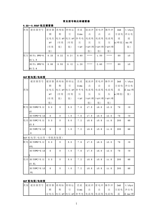
常见型号氧化锌避雷器0.22~0.38kV低压避雷器类别避雷器型号避雷器额定电压kV(有效值) 系统标称电压kV(有效值)持续运行电压kV(有效值)直流U1mA参考电压≮kV陡波冲击电流残压≯kV(峰值)雷电冲击电流残压≯kV(峰值)操作冲击电流残压≯kV(峰值)2mS方波电流A(峰值)4/10μs冲击电流kA(峰值)低压(H)Y1.5WS-0.28/1.30.28 0.22 0.24 0.60 ---- 1.30 ---- 50 10(H)Y1.5WS-0.50/2.60.50 0.38 0.42 1.20 ---- 2.60 ---- 50 10 3kV配电型/电站型类别避雷器型号避雷器额定电压kV(有效值)系统标称电压kV(有效值)持续运行电压kV(有效值)直流U1mA参考电压≮kV陡波冲击电流残压≯kV(峰值)雷电冲击电流残压≯kV(峰值)操作冲击电流残压≯kV(峰值)2mS方波电流A(峰值)4/10μs冲击电流kA(峰值)配电(H)Y5WS-3.8/153.8 3 3.0 7.5 17.3 15.0 12.8 75 40(H)Y5WS-5/15 5 3 4.0 7.5 17.3 15.0 12.8 75 40 电站(H)Y5WZ-3.8/13.53.8 3 3.0 7.2 15.5 13.5 11.5 200 65(H)Y5WZ-5/13.55 3 4.0 7.2 15.5 13.5 11.5 200 65 3kV配电型/电站型(带脱离装置)配电(H)Y5WS-3.8/15L3.8 3 3.0 7.5 17.3 15.0 12.8 75 40(H)Y5WS-5/15L5 3 4.0 7.5 17.3 15.0 12.8 75 40电站(H)Y5WZ-3.8/13.5L3.8 3 3.0 7.2 15.5 13.5 11.5 200 65(H)Y5WZ-5/13.5L5 3 4.0 7.2 15.5 13.5 11.5 200 65 6kV配电型/电站型类别避雷器型号避雷器额定电压系统标称电压kV持续运行电压kV直流U1mA参考电陡波冲击电流残雷电冲击电流残操作冲击电流残2mS方波电流4/10μs冲击电流kA(峰kV (有效值) (有效值)(有效值)压≮kV压≯kV(峰值)压≯kV(峰值)压≯kV(峰值)A(峰值) 值)配电(H)Y5WS-7.6/307.6 6 6.0 15.0 34.6 30.0 25.6 75 40(H)Y5WS-10/310 6 8.0 15.0 34.6 30.0 25.6 75 40电站(H)Y5WZ-7.6/277.6 6 6.0 14.4 31.0 27.0 23.0 200 65(H)Y5WZ-10/2710 6 8.0 14.4 31.0 27.0 23.0 200 65 6kV配电型/电站型(带脱离装置)配电(H)Y5WS-7.6/30L7.6 6 6.0 15.0 34.6 30.0 25.6 75 40(H)Y5WS-10/30L10 6 8.0 15.0 34.6 30.0 25.6 75 40电站(H)Y5WZ-7.6/27L7.6 6 6.0 14.4 31.0 27.0 23.0 200 65(H)Y5WZ-10/27L10 6 8.0 14.4 31.0 27.0 23.0 200 65 10kV配电型/电站型类别避雷器型号避雷器额定电压kV(有效值) 系统标称电压kV(有效值)持续运行电压kV(有效值)直流U1mA参考电压≮kV陡波冲击电流残压≯kV(峰值)雷电冲击电流残压≯kV(峰值)操作冲击电流残压≯kV(峰值)2mS方波电流A(峰值)4/10μs冲击电流kA(峰值)配电(H)Y5WS-12/35.8 (1)12 10 9.6 18.0 41.2 35.8 30.6 75 40(H)Y5WS-15/45.6 (2)15 10 12.0 23.0 52.5 45.6 39.0 75 40(H)Y5WS-12.7/5012.7 10 10.2 25.0 57.5 50.0 42.5 75 40(H)Y5WS-16.5/5016.5 10 13.2 25.0 57.5 50.0 42.5 75 40(H)Y5WS-17/517 10 13.6 25.0 57.5 50.0 42.5 75 40电站(H)Y5WZ-12/32.4 (1)12 10 9.6 17.4 37.2 32.4 27.6 200 65(H)Y5WS-15/415 10 12.0 21.8 46.5 40.5 34.5 200 650.5 (2)(H)Y5WZ-12.7/4512.7 10 10.2 24.0 51.8 45.0 38.3 200 65(H)Y5WZ-16.5/4516.5 10 13.2 24.0 51.8 45.0 38.3 200 65(H)Y5WZ-17/4517 10 13.6 24.0 51.8 45.0 38.3 200 65 10kV配电型/电站型(带脱离装置)配电(H)Y5WS-12/35.8L(1)12 10 9.6 18.0 41.2 35.8 30.6 75 40(H)Y5WS-15/45.6L(2)15 10 12.0 23.0 52.5 45.6 39.0 75 40(H)Y5WS-12.7/50L12.7 10 10.2 25.0 57.5 50.0 42.5 75 40(H)Y5WS-16.5/50L16.5 10 13.2 25.0 57.5 50.0 42.5 75 40(H)Y5WS-17/50L17 10 13.6 25.0 57.5 50.0 42.5 75 40电站(H)Y5WZ-12/32.4L(1)12 10 9.6 17.4 37.2 32.4 27.6 200 65(H)Y5WS-15/40.5L(2)15 10 12.0 21.8 46.5 40.5 34.5 200 65(H)Y5WZ-12.7/45L12.7 10 10.2 24.0 51.8 45.0 38.3 200 65(H)Y5WZ-16.5/45L16.5 10 13.2 24.0 51.8 45.0 38.3 200 65(H)Y5WZ-17/45L17 10 13.6 24.0 51.8 45.0 38.3 200 65注:(1)—此型避雷器用于中性点经低电阻接地的电网;(2)—此型避雷器用于中性点经消弧线圈接地的电网。
- 1、下载文档前请自行甄别文档内容的完整性,平台不提供额外的编辑、内容补充、找答案等附加服务。
- 2、"仅部分预览"的文档,不可在线预览部分如存在完整性等问题,可反馈申请退款(可完整预览的文档不适用该条件!)。
- 3、如文档侵犯您的权益,请联系客服反馈,我们会尽快为您处理(人工客服工作时间:9:00-18:30)。
Document Number Optocoupler, Phototransistor Output, Low Input CurrentFeatures•Good CTR Linearity Depending on Forward Current•Low CTR Degradation•High Collector-emitter Voltage, V CEO = 55 V •Isolation Test Voltage, 5300 V RMS •Low Coupling Capacitance•End-Stackable, 0.100 " (2.54 mm) Spacing •High Common-mode Interference Immunity •Lead-free component•Component in accordance to RoHS 2002/95/EC and WEEE 2002/96/ECAgency Approvals•UL1577, File No. E52744 System Code H or J, Double Protection •CSA 93751•DIN EN 60747-5-2 (VDE0884)DIN EN 60747-5-5 pending Available with Option 1ApplicationsTelecomIndustrial ControlsBattery Powered Equipment Office MachinesDescriptionThe SFH618A (DIP) and SFH6186 (SMD) feature a high current transfer ratio, low coupling capacitance and high isolation voltage. These couplers have a GaAs infrared diode emitter, which is optically cou-pled to silicon planar phototransistor detector, and is incorporated in a plastic DIP-4 or SMD package.The coupling devices are designed for signal trans-mission between two electrically separated circuits.The couplers are end-stackable with 2.54 mm lead spacing.Creepage and clearance distances of > 8.0 mm achieved with option 6. This version complies with IEC 60950 (DIN VDE 0805) for reinforced insulation to an operation voltage of 400 V RMS or DC.Order InformationFor additional information on the available options refer to Option Information.PartRemarksSFH618A-2CTR 63 - 125 %, DIP-4SFH618A-3CTR 100 - 200 %, DIP-4SFH618A-4CTR 160 - 320 %, DIP-4SFH618A-5CTR 250 - 500 %, DIP-4SFH6186-2CTR 63 - 125 %, SMD-4SFH6186-3CTR 100 - 200 %, SMD-4SFH6186-4CTR 160 - 320 %, SMD-4SFH6186-5CTR 250 - 500 %, SMD-4SFH618A-3X006CTR 100 - 200 %, DIP-4 400 mil (option 6)SFH618A-3X007CTR 100 - 200 %, SMD-4 (option 7)SFH618A-4X006CTR 160 - 320 %, DIP-4 400 mil (option 6)SFH618A-5X006CTR 250 - 500 %, DIP-4 400 mil (option 6)SFH618A-5X007CTR 250 - 500 %, SMD-4 (option 7) Document Number 83673Absolute Maximum RatingsT amb = 25°C, unless otherwise specifiedStresses in excess of the absolute Maximum Ratings can cause permanent damage to the device. Functional operation of the device is not implied at these or any other conditions in excess of those given in the operational sections of this document. Exposure to absolute Maximum Rating for extended periods of the time can adversely affect reliability.InputOutputCouplerParameterTest conditionSymbol Value Unit Reverse voltage V R 6.0V Power dissipationP diss70mWParameterTest conditionSymbol Value Unit Collector-emitter voltage V CE 55V Emitter-collector voltage V EC 7.0V Collector currentI C 50mA t p ≤ 1.0 msI C 100mA Power dissipationP diss150mWParameterTest conditionSymbol Value Unit Isolation test voltage between emitter and detector, refer to Climate DIN 40046, part2, Nov.74V ISO5300V RMSCreepage distance ≥ 7.0mm Clearance≥ 7.0mm Insulation thickness between emitter and detector≥ 0.4mmComparative tracking index per DIN IEC 112/VDEO 303, part 1175Isolation resistance V IO = 500 V, T amb = 25°C R IO ≥ 1012ΩV IO = 500 V, T amb = 100°CR IO ≥ 1011ΩStorage temperature range T stg - 55 to +150°C Ambient temperature range T amb - 55 to +100°C Junction temperature T j 100°C Soldering temperaturemax. 10 s. Dip Soldering distance to seating plane ≥ 1.5 mmT sld260°CDocument Number Electrical CharacteristicsT amb = 25°C, unless otherwise specifiedMinimum and maximum values are testing requirements. Typical values are characteristics of the device and are the result of engineering evaluation. Typical values are for information only and are not part of the testing requirements.InputOutputCoupler05010015020025507510012515018485P –P o w e r D i s s i p a t i o n (m W )to t T amb – Ambient T emperature ( q C )Figure 1. Permissible Power Dissipation vs. Ambient TemperatureParameterTest conditionSymbol MinTyp.Max Unit Forward voltage I F = 5.0 mA V F 1.1 1.5V Reverse current V R = 6.0 VI R .0110µA Capacitance V R = 0 V, f = 1.0 MHzC O 25pF Thermal resistanceR thja1070K/WParameterTest conditionSymbol MinTyp.Max Unit Collector-emitter leakage currentV CE = 10 VI CEO 10200nA Collector-emitter capacitance V CE = 5.0 V, f = 1.0 MHzC CE 7pF Thermal resistanceR thja500K/WParameterTest conditionPart Symbol MinTyp.Max Unit Collector-emitter saturation voltageI C = 0.32 mA, I F = 1.0 mA SFH618A-2 SFH6186-2V CEsat 0.250.4V I C = 0.5 mA, I F = 1.0 mA SFH618A-3 SFH6186-3V CEsat 0.250.4V I C = 1.25 mA, I F = 1.0 mA SFH618A-4 SFH6186-4V CEsat 0.250.4V I C = 0.8 mA, I F = 1.0 mASFH618A-5 SFH6186-5V CEsat 0.250.4V Coupling capacitanceC C0.25pF Document Number 83673Current Transfer RatioSwitching CharacteristicsTypicalParameterTest conditionPart Symbol Min Typ.Max Unit I C /I FI F = 1.0 mA, V CE = 0.5 V SFH618A-2 SFH6186-2CTR 63125%I F = 0.5 mA, V CE = 1.5 V SFH618A-2 SFH6186-2CTR 3275%I F = 1.0 mA, V CE = 0.5 V SFH618A-3 SFH6186-3CTR 100200%I F = 0.5 mA, V CE = 1.5 V SFH618A-3 SFH6186-3CTR 50120%I F = 1.0 mA, V CE = 0.5 V SFH618A-4 SFH6186-4CTR 160320%I F = 0.5 mA, V CE = 1.5 V SFH618A-4 SFH6186-4CTR 80200%I F = 1.0 mA, V CE = 0.5 V SFH618A-5 SFH6186-5CTR 250500%I F = 0.5 mA, V CE = 1.5 VSFH618A-5 SFH6186-5CTR125300%ParameterTest conditionSymbol MinTyp.MaxUnit Turn-on time V CC = 5.0 V, I C = 2.0 mA, R L = 100 Ωt on 6.0µs Rise time V CC = 5.0 V, I C = 2.0 mA, R L = 100 Ωt r 3.5µs Turn-off time V CC = 5.0 V, I C = 2.0 mA, R L = 100 Ωt off 5.5µs Fall timeV CC = 5.0 V, I C = 2.0 mA, R L = 100 Ωt f5.0µsFigure 2. Test Circuit isfh618a_10V OUTV =5VFigure 3. Test Circuit and Waveformsisfh618a_1210%90%PulsePulsetDocument Number Typical Characteristics (Tamb = 25 °C unless otherwise specified)Figure 4. Current Transfer Ratio (typ.)Figure 5. Current Transfer Ratio (typ.)Figure 6. Diode Forward Voltage (typ.)isfh618a_01V CE =0.5V,C TR =f (T A )isfh618a_01V CE =0.5V,C TR =f (T A )isfh618a_02isfh618a_03T A =25°C,V F =f (I F )Figure 7. Diode Forward Voltage (typ.)Figure 8. Transistor CapacitanceFigure 9. Output Characteristicsisfh618a_04I F =1.0mA,V F =f (T A )isfh618a_05T A =25°C,f =1.0MHz,C EE =f (V CE )T A =25°C,C E =f (V CE ,I F )isfh618a_06 Document Number 83673Package Dimensions in Inches (mm)Figure 10. Permissible Forward Current Diode isfh618a_07I F =f (T A )Figure 11. Switching times (typ.)isfh618a_09T A =25°C,I F =1.0mA,V CC =5.0V,t ON ,t R ,t OFF ,t F ,=f (R L )Package Dimensions in Inches (mm)Document Number Ozone Depleting Substances Policy StatementIt is the policy of Vishay Semiconductor GmbH to1.Meet all present and future national and international statutory requirements.2.Regularly and continuously improve the performance of our products, processes, distribution andoperatingsystems with respect to their impact on the health and safety of our employees and the public, as well as their impact on the environment.It is particular concern to control or eliminate releases of those substances into the atmosphere which are known as ozone depleting substances (ODSs).The Montreal Protocol (1987) and its London Amendments (1990) intend to severely restrict the use of ODSs and forbid their use within the next ten years. Various national and international initiatives are pressing for an earlier ban on these substances.Vishay Semiconductor GmbH has been able to use its policy of continuous improvements to eliminate the use of ODSs listed in the following documents.1.Annex A, B and list of transitional substances of the Montreal Protocol and the London Amendmentsrespectively2.Class I and II ozone depleting substances in the Clean Air Act Amendments of 1990 by the EnvironmentalProtection Agency (EPA) in the USA3.Council Decision 88/540/EEC and 91/690/EEC Annex A, B and C (transitional substances) respectively. Vishay Semiconductor GmbH can certify that our semiconductors are not manufactured with ozone depleting substances and do not contain such substances.We reserve the right to make changes to improve technical designand may do so without further notice.Parameters can vary in different applications. All operating parameters must be validated for each customer application by the customer. Should the buyer use Vishay Semiconductors products for any unintended or unauthorized application, the buyer shall indemnify Vishay Semiconductors against all claims, costs, damages, and expenses, arising out of, directly or indirectly, any claim of personal damage, injury or death associated with such unintended or unauthorized use.Vishay Semiconductor GmbH, P.O.B. 3535, D-74025 Heilbronn, GermanyTelephone: 49 (0)7131 67 2831, Fax number: 49 (0)7131 67 2423 Document Number 83673。
