HCF4555M013TR,HCF4555BEY, 规格书,Datasheet 资料
ntse0103fzl49规格书

ntse0103fzl49规格书摘要:一、背景介绍二、产品规格概述1.产品名称与型号2.产品用途与特点3.产品主要性能参数三、产品结构与组成1.主体结构2.关键部件及其功能四、产品适用范围与禁忌症五、产品优势与亮点六、产品使用方法与注意事项七、产品维护与保养八、产品售后服务与保障九、总结与展望正文:一、背景介绍随着科技的发展和市场的需求,医疗器械行业不断创新,为满足患者和医生的需求,推出了一款具有代表性的产品——ntse0103fzl49。
本篇稿件将详细介绍该产品的规格与性能,帮助读者更好地了解和应用这款产品。
二、产品规格概述1.产品名称与型号本文介绍的产品名为ntse0103fzl49,是一款高性能的医疗器械。
2.产品用途与特点tse0103fzl49主要用于治疗和监测相关疾病,具有以下特点:a.高效性:采用先进的技术,提高治疗效果;b.安全性:严格遵循国家相关法规和标准,确保产品安全;c.便捷性:设计紧凑,操作简便,便于携带和维护。
3.产品主要性能参数tse0103fzl49的主要性能参数包括:a.工作电压:直流5V;b.工作温度:5℃-40℃;c.存储温度:-20℃-60℃;d.功率:≤5W;e.尺寸:长×宽×高(mm);f.重量:约2kg。
三、产品结构与组成1.主体结构tse0103fzl49的主体结构由主机、显示器、操作面板、接口等部分组成。
2.关键部件及其功能a.主机:负责控制整个设备的运行,包括数据处理、存储和传输;b.显示器:实时显示设备的工作状态和数据;c.操作面板:包括启动、停止、调整等按钮,方便用户进行参数设置和操作;d.接口:用于与其他设备连接,实现数据交换和协同工作。
四、产品适用范围与禁忌症tse0103fzl49适用于以下范围:a.医疗机构:用于疾病的诊断、治疗和监测;b.康复中心:用于康复治疗和训练;c.家庭护理:用于家庭医疗保健和康复。
禁忌症:a.对产品材质过敏者;b.存在出血倾向的患者;c.未满18周岁的未成年人。
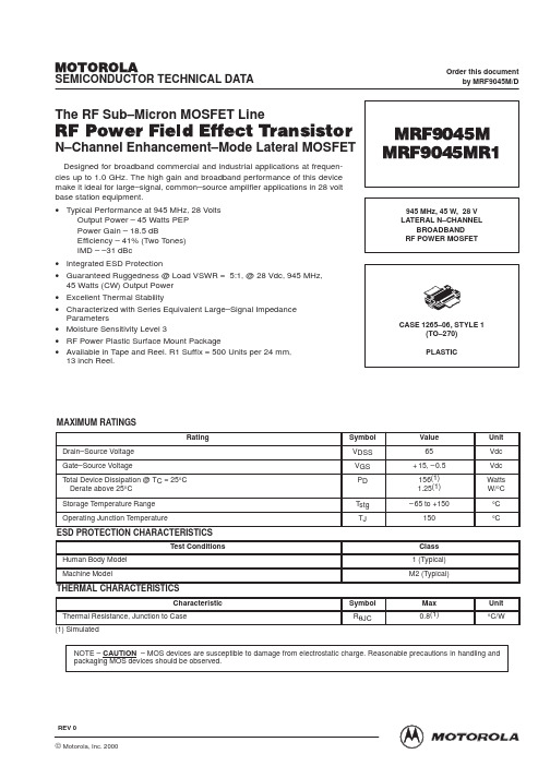
MRF9045M中文资料
Z3 Z4 Z5 Z6 Z7 Z8 Z9 Z10 Z11 Z12 Z13
0.14″ x 0.32″ 0.47″ x 0.32″ 0.16″ x 0.32″ x 0.62″ Tapered 0.18″ x 0.62″ 0.56″ x 0.62″ 0.33″ x 0.32″ 0.14″ x 0.32″ 0.36″ x 0.08″ 1.01″ x 0.08″ 0.15″ x 0.08″ 0.29″ x 0.08″
N–Channel Enhancement–Mode Lateral MOSFET
MRF9045M MRF9045MR1
945 MHz, 45 W, 28 V LATERAL N–CHANNEL BROADBAND RF POWER MOSFET
CASE 1265–06, STYLE 1 (TO–270) PLASTIC
mrf9045m中文资料lm358中文资料12864中文资料lm393中文资料mpu6050中文资料lm324中文资料7805中文资料max232中文资料tl431中文资料op07中文资料74hc595中文资料
元器件交易网
MOTOROLA
SEMICONDUCTOR TECHNICAL DATA
MAXIMUM RATINGS
Rating Drain–Source Voltage Gate–Source Voltage Total Device Dissipation @ TC = 25°C Derate above 25°C Storage Temperature Range Operating Junction Temperature Symbol VDSS VGS PD Tstg TJ Value 65 + 15, – 0.5 156(1) 1.25(1) – 65 to +150 150 Unit Vdc Vdc Watts W/°C °C °C
ROLLEI-DescriptionRolleiDSMMSRP45x66x6cmCameras

66155 66151 66156 66152 66153
$5,999 $3,549
$6,499 $7,999
58080 58001 58701
66158 66157 66159
$5,999 $3,649 $6,499
58502 66160 $7,999
86706 66101 $2,889 86675 66102 $2,489
Focusing Screens
AF- High-D-Screen for 6008AF and Hy6 and microprism ring (standard screen for 6003 professional) HD screen, super-bright screen with horizontal split image spot and extremely fine texture Bright matte screen 4.5x6 vertical and horizontal indication Bright matte screen with microprism spot Clear glass screen
1/7
Rollei DSM MSRP 66032 $12,048
58601 66031 $8,599 66030
56651 66014 $4,299
56650 66012 $2,499 56602 66015 $4,299 56600 66019 $2,799 10722 66351 $69
54080 54001 54120 54701 54502
Makro Planar 4/120 HFT PQS - filter size VI (Special order only.) Sonnar 4/150 mm HFT PQS - filter size VI Sonnar 5.6/250 mm HFT PQS - filter size IV *Lenses are made by Carl Zeiss, Oberkochen, Germany,
TLC555C芯片
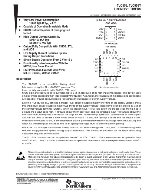
LinCMOS is a trademark of Texas Instruments Incorporated.PRODUCTION DATA information is current as of publication date.Products conform to specifications per the terms of Texas Instrumentsstandard warranty. Production processing does not necessarily includetesting of all parameters.64POST OFFICE BOX 655303IMPORTANT NOTICETexas Instruments and its subsidiaries (TI) reserve the right to make changes to their products or to discontinue any product or service without notice, and advise customers to obtain the latest version of relevant information to verify, before placing orders, that information being relied on is current and complete. All products are sold subject to the terms and conditions of sale supplied at the time of order acknowledgement, including those pertaining to warranty, patent infringement, and limitation of liability.TI warrants performance of its semiconductor products to the specifications applicable at the time of sale in accordance with TI’s standard warranty. Testing and other quality control techniques are utilized to the extent TI deems necessary to support this warranty. Specific testing of all parameters of each device is not necessarily performed, except those mandated by government requirements.CERTAIN APPLICATIONS USING SEMICONDUCTOR PRODUCTS MAY INVOLVE POTENTIAL RISKS OF DEATH, PERSONAL INJURY, OR SEVERE PROPERTY OR ENVIRONMENTAL DAMAGE (“CRITICAL APPLICATIONS”). TI SEMICONDUCTOR PRODUCTS ARE NOT DESIGNED, AUTHORIZED, OR WARRANTED TO BE SUITABLE FOR USE IN LIFE-SUPPORT DEVICES OR SYSTEMS OR OTHER CRITICAL APPLICATIONS. INCLUSION OF TI PRODUCTS IN SUCH APPLICATIONS IS UNDERSTOOD TO BE FULLY AT THE CUSTOMER’S RISK.In order to minimize risks associated with the customer’s applications, adequate design and operating safeguards must be provided by the customer to minimize inherent or procedural hazards.TI assumes no liability for applications assistance or customer product design. TI does not warrant or represent that any license, either express or implied, is granted under any patent right, copyright, mask work right, or other intellectual property right of TI covering or relating to any combination, machine, or process in which such semiconductor products or services might be or are used. TI’s publication of information regarding any third party’s products or services does not constitute TI’s approval, warranty or endorsement thereof.Copyright © 1998, Texas Instruments Incorporated。
瑞丰WI -E-045 A1 产品说明书

applications which has special requirement in quality and reliability. 如产品需要用在有特殊质量要求及可靠性要求的地方,请提前咨询瑞丰的销售人员以取得相关信息。
4. Without Refond permission, customer shouldn’t disassemble and analyze the LEDs. If the customer find invalid product, please notice Refond in written form.在取得瑞丰的同意前,客户不应该对产品进行拆解分析,如发现失效产品,请直接书面通知瑞丰。
Features 特征Extremely wide viewing angle.发光角度大Suitable for all SMT assembly and solder process.适用于所有的SMT 组装和焊接工艺 Moisture sensitivity level: Level 3.防潮等级 Level 3Package:4000pcs/reel.包装每卷4000pcsRoHS compliant. 满足RoHS 要求Description 描述The Colour LED which was fabricated by using a yellow chip 该产品为黄光LED ,是由黄光芯片封装形成Applications 应用Optical indicator.光学指示Switch and Symbol,Display.开关和标识、显示器等General use.其他应用Package Dimension 外观尺寸NOTES:1.All dimensions units are millimeters. (所有尺寸标注单位为毫米)2.All dimensions tolerances are ±0.2mm unless otherwise noted. (除特别标注外,所有尺寸公差为±0.2毫米)Electrical / Optical Characteristics at Ts=25°C 电性与光学特性Absolute Maximum Ratings at Ts=25°C绝对最大值Typical optical characteristics curves典型光学特性曲线°C)Packaging Specifications 包装规格⏹Tape Dimensions 载带尺寸⏹Note:The tolerances unless mentioned ±0.1mm. Unit : mm 注:未注公差为±0.1毫米,尺寸单位:毫米。
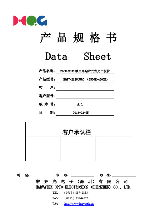
宏齐光电子(深圳)有限公司 2835自然白规格书
二、外形尺寸及建议焊盘尺寸:
①
②
①
Polarity
②
推荐焊盘尺寸:
① ②
②
②
① ②
注:
1. 单位 : 毫米(mm) ; 2. 公差 :如无特别标注则为± 0.10 mm;
HARVATEK OPTO-ELECTRONICS(SHENZHEN)CO., LTD.
0.4033 0.406 0.394 0.3916 0.4006 0.4033 0.3916 0.3893 0.3979 0.4006 0.3893 0.3869 0.3952 0.3979 0.3869 0.3846 0.3925 0.3952 0.3846 0.3822 0.3897 0.3925
符 号
Pd IFP IF VR Topr Tstg Tsol ESD
最大额定值
180 80 60 5 -30°C -40°C ~ ~ + 85°C + 90°C
单 位
mW mA mA V
回流焊 : 260°C ,10s 手动焊 : 300°C ,3s 2000 V
五、光电参数
参数 光通亮 显指 半光强视角 色坐标 色温 正向电压 反向电流
发布日期 2014.02.25 页码
8 of 13
八、标签标识:
CAT:光强 (单位(mcd) ) HUE:色坐标 REF:电压 (单位(V) )
九、包装载带与圆盘尺寸:
φ 13.0
注:
1、 尺寸单位为毫米(mm); 2、 尺寸公差是±0.1mm;
HARVATEK OPTO-ELECTRONICS(SHENZHEN)CO., LTD.
宏齐光电子(深圳)有限公司
HARVATEK OPTO-ELECTRONICS(SHENZHEN)CO., LTD.
CD4555BEE4中文资料
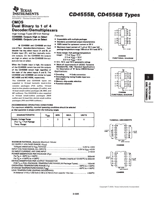
Data sheet acquired from Harris Semiconductor SCHS087D − Revised October 2003The CD4555B and CD4556B types are supplied in 16-lead hermetic dual-in-line ceramic packages (F3A suffix), 16-lead dual-in-line plastics packages (E suffix), and 16-lead small-outline packages (M, M96, and MT suffixes). The CD4555B is also supplied in 16-lead small-outline packages (NSR suffix) and 16-lead thin shrink small-outline packages (PW and PWR suffixes.)PACKAGING INFORMATIONOrderable Device Status(1)PackageType PackageDrawingPins PackageQtyEco Plan(2)Lead/Ball Finish MSL Peak Temp(3)7704701EA ACTIVE CDIP J161TBD A42SNPB N/A for Pkg Type 7704801EA ACTIVE CDIP J161TBD A42SNPB N/A for Pkg Type CD4555BE ACTIVE PDIP N1625Pb-Free(RoHS)CU NIPDAU N/A for Pkg TypeCD4555BEE4ACTIVE PDIP N1625Pb-Free(RoHS)CU NIPDAU N/A for Pkg Type CD4555BF3A ACTIVE CDIP J161TBD A42SNPB N/A for Pkg Type CD4555BM ACTIVE SOIC D1640Green(RoHS&no Sb/Br)CU NIPDAU Level-1-260C-UNLIMCD4555BM96ACTIVE SOIC D162500Green(RoHS&no Sb/Br)CU NIPDAU Level-1-260C-UNLIMCD4555BM96E4ACTIVE SOIC D162500Green(RoHS&no Sb/Br)CU NIPDAU Level-1-260C-UNLIMCD4555BM96G4ACTIVE SOIC D162500Green(RoHS&no Sb/Br)CU NIPDAU Level-1-260C-UNLIMCD4555BME4ACTIVE SOIC D1640Green(RoHS&no Sb/Br)CU NIPDAU Level-1-260C-UNLIMCD4555BMG4ACTIVE SOIC D1640Green(RoHS&no Sb/Br)CU NIPDAU Level-1-260C-UNLIMCD4555BMT ACTIVE SOIC D16250Green(RoHS&no Sb/Br)CU NIPDAU Level-1-260C-UNLIMCD4555BMTE4ACTIVE SOIC D16250Green(RoHS&no Sb/Br)CU NIPDAU Level-1-260C-UNLIMCD4555BMTG4ACTIVE SOIC D16250Green(RoHS&no Sb/Br)CU NIPDAU Level-1-260C-UNLIMCD4555BNSR ACTIVE SO NS162000Green(RoHS&no Sb/Br)CU NIPDAU Level-1-260C-UNLIMCD4555BNSRE4ACTIVE SO NS162000Green(RoHS&no Sb/Br)CU NIPDAU Level-1-260C-UNLIMCD4555BNSRG4ACTIVE SO NS162000Green(RoHS&no Sb/Br)CU NIPDAU Level-1-260C-UNLIMCD4555BPW ACTIVE TSSOP PW1690Green(RoHS&no Sb/Br)CU NIPDAU Level-1-260C-UNLIMCD4555BPWE4ACTIVE TSSOP PW1690Green(RoHS&no Sb/Br)CU NIPDAU Level-1-260C-UNLIMCD4555BPWG4ACTIVE TSSOP PW1690Green(RoHS&no Sb/Br)CU NIPDAU Level-1-260C-UNLIMCD4555BPWR ACTIVE TSSOP PW162000Green(RoHS&no Sb/Br)CU NIPDAU Level-1-260C-UNLIMCD4555BPWRE4ACTIVE TSSOP PW162000Green(RoHS&no Sb/Br)CU NIPDAU Level-1-260C-UNLIMCD4555BPWRG4ACTIVE TSSOP PW162000Green(RoHS&no Sb/Br)CU NIPDAU Level-1-260C-UNLIMCD4556BE ACTIVE PDIP N1625Pb-Free(RoHS)CU NIPDAU N/A for Pkg TypeCD4556BEE4ACTIVE PDIP N1625Pb-Free(RoHS)CU NIPDAU N/A for Pkg TypeCD4556BF ACTIVE CDIP J161TBD A42SNPB N/A for Pkg Type CD4556BF3A ACTIVE CDIP J161TBD A42SNPB N/A for Pkg TypeOrderable Device Status(1)PackageType PackageDrawingPins PackageQtyEco Plan(2)Lead/Ball Finish MSL Peak Temp(3)CD4556BF3AS2283OBSOLETE CDIP J16TBD Call TI Call TI CD4556BM ACTIVE SOIC D1640Green(RoHS&no Sb/Br)CU NIPDAU Level-1-260C-UNLIMCD4556BM96ACTIVE SOIC D162500Green(RoHS&no Sb/Br)CU NIPDAU Level-1-260C-UNLIMCD4556BM96E4ACTIVE SOIC D162500Green(RoHS&no Sb/Br)CU NIPDAU Level-1-260C-UNLIMCD4556BM96G4ACTIVE SOIC D162500Green(RoHS&no Sb/Br)CU NIPDAU Level-1-260C-UNLIMCD4556BME4ACTIVE SOIC D1640Green(RoHS&no Sb/Br)CU NIPDAU Level-1-260C-UNLIMCD4556BMG4ACTIVE SOIC D1640Green(RoHS&no Sb/Br)CU NIPDAU Level-1-260C-UNLIMCD4556BMT ACTIVE SOIC D16250Green(RoHS&no Sb/Br)CU NIPDAU Level-1-260C-UNLIMCD4556BMTE4ACTIVE SOIC D16250Green(RoHS&no Sb/Br)CU NIPDAU Level-1-260C-UNLIMCD4556BMTG4ACTIVE SOIC D16250Green(RoHS&no Sb/Br)CU NIPDAU Level-1-260C-UNLIM(1)The marketing status values are defined as follows:ACTIVE:Product device recommended for new designs.LIFEBUY:TI has announced that the device will be discontinued,and a lifetime-buy period is in effect.NRND:Not recommended for new designs.Device is in production to support existing customers,but TI does not recommend using this part in a new design.PREVIEW:Device has been announced but is not in production.Samples may or may not be available.OBSOLETE:TI has discontinued the production of the device.(2)Eco Plan-The planned eco-friendly classification:Pb-Free(RoHS),Pb-Free(RoHS Exempt),or Green(RoHS&no Sb/Br)-please check /productcontent for the latest availability information and additional product content details.TBD:The Pb-Free/Green conversion plan has not been defined.Pb-Free(RoHS):TI's terms"Lead-Free"or"Pb-Free"mean semiconductor products that are compatible with the current RoHS requirements for all6substances,including the requirement that lead not exceed0.1%by weight in homogeneous materials.Where designed to be soldered at high temperatures,TI Pb-Free products are suitable for use in specified lead-free processes.Pb-Free(RoHS Exempt):This component has a RoHS exemption for either1)lead-based flip-chip solder bumps used between the die and package,or2)lead-based die adhesive used between the die and leadframe.The component is otherwise considered Pb-Free(RoHS compatible)as defined above.Green(RoHS&no Sb/Br):TI defines"Green"to mean Pb-Free(RoHS compatible),and free of Bromine(Br)and Antimony(Sb)based flame retardants(Br or Sb do not exceed0.1%by weight in homogeneous material)(3)MSL,Peak Temp.--The Moisture Sensitivity Level rating according to the JEDEC industry standard classifications,and peak solder temperature.Important Information and Disclaimer:The information provided on this page represents TI's knowledge and belief as of the date that it is provided.TI bases its knowledge and belief on information provided by third parties,and makes no representation or warranty as to the accuracy of such information.Efforts are underway to better integrate information from third parties.TI has taken and continues to take reasonable steps to provide representative and accurate information but may not have conducted destructive testing or chemical analysis on incoming materials and chemicals.TI and TI suppliers consider certain information to be proprietary,and thus CAS numbers and other limited information may not be available for release.In no event shall TI's liability arising out of such information exceed the total purchase price of the TI part(s)at issue in this document sold by TI to Customer on an annual basis.TAPE AND REEL INFORMATION*All dimensions are nominalDevicePackage Type Package Drawing Pins SPQReel Diameter (mm)Reel Width W1(mm)A0(mm)B0(mm)K0(mm)P1(mm)W (mm)Pin1Quadrant CD4555BM96SOIC D 162500330.016.4 6.510.3 2.18.016.0Q1CD4555BNSR SO NS 162000330.016.48.210.5 2.512.016.0Q1CD4555BPWR TSSOP PW 162000330.012.47.0 5.6 1.68.012.0Q1CD4556BM96SOICD162500330.016.46.510.32.18.016.0Q1*All dimensions are nominalDevice Package Type Package Drawing Pins SPQ Length(mm)Width(mm)Height(mm) CD4555BM96SOIC D162500333.2345.928.6 CD4555BNSR SO NS162000346.0346.033.0 CD4555BPWR TSSOP PW162000346.0346.029.0 CD4556BM96SOIC D162500333.2345.928.6IMPORTANT NOTICETexas Instruments Incorporated and its subsidiaries(TI)reserve the right to make corrections,modifications,enhancements,improvements, and other changes to its products and services at any time and to discontinue any product or service without notice.Customers should obtain the latest relevant information before placing orders and should verify that such information is current and complete.All products are sold subject to TI’s terms and conditions of sale supplied at the time of order acknowledgment.TI warrants performance of its hardware products to the specifications applicable at the time of sale in accordance with TI’s standard warranty.Testing and other quality control techniques are used to the extent TI deems necessary to support this warranty.Except where mandated by government requirements,testing of all parameters of each product is not necessarily performed.TI assumes no liability for applications assistance or customer product design.Customers are responsible for their products and applications using TI components.To minimize the risks associated with customer products and applications,customers should provide adequate design and operating safeguards.TI does not warrant or represent that any license,either express or implied,is granted under any TI patent right,copyright,mask work right, or other TI intellectual property right relating to any combination,machine,or process in which TI products or services are rmation published by TI regarding third-party products or services does not constitute a license from TI to use such products or services or a warranty or endorsement e of such information may require a license from a third party under the patents or other intellectual property of the third party,or a license from TI under the patents or other intellectual property of TI.Reproduction of TI information in TI data books or data sheets is permissible only if reproduction is without alteration and is accompanied by all associated warranties,conditions,limitations,and notices.Reproduction of this information with alteration is an unfair and deceptive business practice.TI is not responsible or liable for such altered rmation of third parties may be subject to additional restrictions.Resale of TI products or services with statements different from or beyond the parameters stated by TI for that product or service voids all express and any implied warranties for the associated TI product or service and is an unfair and deceptive business practice.TI is not responsible or liable for any such statements.TI products are not authorized for use in safety-critical applications(such as life support)where a failure of the TI product would reasonably be expected to cause severe personal injury or death,unless officers of the parties have executed an agreement specifically governing such use.Buyers represent that they have all necessary expertise in the safety and regulatory ramifications of their applications,and acknowledge and agree that they are solely responsible for all legal,regulatory and safety-related requirements concerning their products and any use of TI products in such safety-critical applications,notwithstanding any applications-related information or support that may be provided by TI.Further,Buyers must fully indemnify TI and its representatives against any damages arising out of the use of TI products in such safety-critical applications.TI products are neither designed nor intended for use in military/aerospace applications or environments unless the TI products are specifically designated by TI as military-grade or"enhanced plastic."Only products designated by TI as military-grade meet military specifications.Buyers acknowledge and agree that any such use of TI products which TI has not designated as military-grade is solely at the Buyer's risk,and that they are solely responsible for compliance with all legal and regulatory requirements in connection with such use. TI products are neither designed nor intended for use in automotive applications or environments unless the specific TI products are designated by TI as compliant with ISO/TS16949requirements.Buyers acknowledge and agree that,if they use any non-designated products in automotive applications,TI will not be responsible for any failure to meet such requirements.Following are URLs where you can obtain information on other Texas Instruments products and application solutions:Products ApplicationsAmplifiers AudioData Converters AutomotiveDSP BroadbandClocks and Timers Digital ControlInterface MedicalLogic MilitaryPower Mgmt Optical NetworkingMicrocontrollers SecurityRFID TelephonyRF/IF and ZigBee®Solutions Video&ImagingWirelessMailing Address:Texas Instruments,Post Office Box655303,Dallas,Texas75265Copyright©2008,Texas Instruments Incorporated。
FT550 高精度恒流 恒压反馈控制芯片
封装实物
引脚号 1 2 3 4
引脚名 VO LED Rs GND
功能 恒压输出端口 接光耦器件 恒流采样端
接地端
Rev1.1
SOT23-5 封装 俯视图
订单型号
FT550-SOT-23-5
器件标记
A50XX XX 可变,代表是这一年 的第几周生产(13 年第 1 周为 A5001 , 13 年 第 15 周 为 A5015)
特性
·最低成本方案,外围仅需一个电阻两个电容 ·集成 CV/CC 控制 ·高精度的 5V 恒压输出 ·可调节的恒流电流,恒流采样电压仅 100mV
应用
·集成 TL431 及外围的分压电阻和补偿网络 ·小尺寸 TO-94,SOT23-5 封装
充电器、适配器 白光 LED 驱动器 小家电电源转换器等
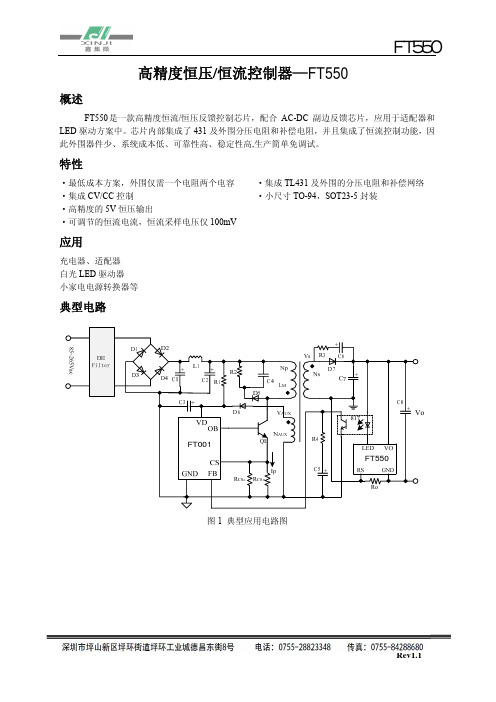
典型电路
高精度恒压/恒流控制器— FT550
FT550
概述
FT550是一款高精度恒流/恒压反馈控制芯片,配合 AC-DC 副边反馈芯片,应用于适配器和 LED 驱动方案中。芯片内部集成了 431 及外围分压电阻和补偿电阻,并且集成了恒流控制功能,因 此外围器件少、系统成本低、可靠性高、稳定性高,生产简单免调试。
FT550
(4)恒流/限压方案 2:驱动多颗串联 LED 方案,以两颗为例
驱动两颗 LED 时,由于 FT550 输出最高典型值为 5V,所以采用如图 11 的原理图。次级两组 变压器的匝数比为 1:1 时,VB=2VA,确保了 LED 两端的电压。
FT550
图 11 恒流驱动两颗 LED 原理图 图 11 所示电路为驱动多颗 LED 串联的典型应用,次级与辅助部分电路与图 8 电路相同
Resistor,2M,1/4W, ± 5% Resistor,270K,1/2W, ± 5% Resistor,47R,1/8W, ± 5% Resistor,2K,1/8W, ± 5% Resistor,3R,1/4W, ± 1% Resistor,2.2R,1/4W, ± 1% Resistor,0.2R,1/2W, ± 1%
启珑微电子产品手册说明书

产品手册PRODUCT MANUAL(北京︶有限公司并一直致力于为工业智能控制、医疗设备、轨道交通、智能交通以及智能家居等领域提供更优质的产品与服务。
公司具有深厚的文化底蕴,由多位有欧美留学、工作经历的归国人员创办,坚实的理论功底和丰富的芯片设计经验奠定了启珑微电子的高起点和高水准,并迅速成长为业内具有自主知识产权的中国IC设计品牌之一。
产品手册01序号产品型号封装形式产品概述兼容型号1CLM811HST-AXC TQFP-48SL811HST-AXC 2CLCP82C55AZ DIP-40CP82C55AZ 3CLIP82C55AZ DIP-40IP82C55AZ 4CLCS82C55AZ PLCC-44CS82C55AZ 5CLIS82C55AZ PLCC-44IS82C55AZ 6CLCQ82C55AZ MQFP-44CQ82C55AZ 7CLIQ82C55AZ MQFP-44IQ82C55AZ 8CLID82C55AZ DIP-40ID82C55A 9CLMD82C55A/B DIP-40MD82C55A/B 10CLMD82C55QA DIP-40MD82C55QA 11CLM65HVD230D SOIC-8SN65HVD230D 12CLM65HVD230QD SOIC-8SN65HVD230QD 13CLM65HVD231D SOIC-8SN65HVD231D 14CLM65HVD231QD SOIC-8SN65HVD231QD 15CLM65HVD232D SOIC-8SN65HVD232D 16CLM65HVD232QD SOIC-8SN65HVD232QD 17CLM65HVD233D SOIC-8具有待机模式和环回功能的 3.3V SN65HVD233D 18CLM65HVD233HD SOIC-8具有待机模式和环回功能的 3.3V SN65HVD233HD 19CLM65HVD233QDRQ1SOIC-8具有待机模式和环回功能的 3.3V SN65HVD233QDRQ120CLM65HVD233MDREP SOIC-8具有待机模式和环回功能的 3.3V SN65HVD233MDREP产品手册02序号产品型号封装形式产品概述兼容型号21CLM65HVD234D SOIC-8SN65HVD234D 22CLM65HVD234QDRQ1SOIC-8SN65HVD234QDRQ123CLM65HVD235D SOIC-8SN65HVD235D 24CLM65HVD235QDRQ1SOIC-8SN65HVD235QDRQ125CLM75176BPS SOIC-8SN75176BPSR 26CLM75176BDR SOIC-8SN75176BDR 27CLM75176ADR SOIC-8SN75176ADR 28CLM75176AP DIP-8SN75176AP 29CLM76176BP DIP-8SN75176BP 30CLM75179BPS SOIC-8SN75179BPS 31CLM75179BDR SOIC-8SN75179BDR 32CLM75179AP DIP-8SN75179AP 33CLM75179BP DIP-8SN75179BP 34CLM65HVD08D SOIC-8SN65HVD08D 35CLM65HVD08P DIP-8SN65HVD08P 36CLM65HVD75D SOIC-8具有IEC ESD保护功能和20Mbps的SN65HVD75D 37CLM65HVD75DGK VSSOIC-8具有IEC ESD保护功能和20Mbps的SN65HVD75DGK 38CLM65HVD75DRBT VDFN-8具有IEC ESD保护功能和20Mbps的SN65HVD75DRBT 39CLM3085CPA+DIP-8(10Mbps)、限摆率RS-485/MAX3085CPA+40CLM3085EPA+DIP-8(10Mbps)、限摆率RS-485/MAX3085EPA+产品手册03序号产品型号封装形式产品概述兼容型号41CLM3085EEPA DIP-8(10Mbps)、限摆率RS-485/MAX3085EEPA 42CLM3085CSA+T SOIC-8(10Mbps)、限摆率RS-485/MAX3085CSA+43CLM3085ECSA+T MSOIC-8(10Mbps)、限摆率RS-485/MAX3085ECSA+T 44CLM3085ESA+T SOIC-8(10Mbps)、限摆率RS-485/MAX3085ESA+45CLM3085EESA+T SOIC-8(10Mbps)、限摆率RS-485/MAX3085EESA+46CLM3088CSA+T SOIC-8MAX3088CSA+T 47CLM3088ECSA+T SOIC-8MAX3088ECSA+T 48CLM3088ESA+T SOIC-8MAX3088ESA+T 49CLM3088EESA+T SOIC-8MAX3088EESA+T 50CLM3088CPA+DIP-8MAX3088CPA+51CLM3088ECPA+DIP-8MAX3088ECPA+52CLM3088EPA+DIP-8MAX3088EPA+53CLM3088EEPA+DIP-8MAX3088EEPA+54CLM485CPA+DIP-8低功耗、限摆率、RS-485/RS-422MAX485CPA+55CLM485ECPA+DIP-8低功耗、限摆率、RS-485/RS-422MAX485ECPA+56CLM485EPA+DIP-8低功耗、限摆率、RS-485/RS-422MAX485EPA+57CLM485EEPA+DIP-8低功耗、限摆率、RS-485/RS-422MAX485EEPA+58CLM485CSA+SOIC-8低功耗、限摆率、RS-485/RS-422MAX485CSA+59CLM485ESA+SOIC-8低功耗、限摆率、RS-485/RS-422MAX485ESA+60CLM485EESA+SOIC-8低功耗、限摆率、RS-485/RS-422MAX485EESA+产品手册04序号产品型号封装形式产品概述兼容型号61CLM3490CSA+SOIC-8 3.3V供电、10Mbps、限摆率、真MAX3490CSA+62CLM3490ECSA+SOIC-8 3.3V供电、10Mbps、限摆率、真MAX3490ESA+63CLM3490ESA+SOIC-8 3.3V供电、10Mbps、限摆率、真MAX3490ESA+64CLM3490EESA+SOIC-8 3.3V供电、10Mbps、限摆率、真MAX3490EESA+65CLM3491CSD SOP-14 3.3V供电、10Mbps、限摆率、真MAX3491CSD+66CLM3491ECSD+SOP-14 3.3V供电、10Mbps、限摆率、真MAX3491ECSD+67CLM3491ESD+SOP-14 3.3V供电、10Mbps、限摆率、真MAX3491ESD+68CLM3491EESD+SOP-14 3.3V供电、10Mbps、限摆率、真MAX3491EESD+69CLM490CSA+SOIC-8低功耗、限摆率、RS-485/RS-422MAX490CSA+70CLM490ECSA+SOIC-8低功耗、限摆率、RS-485/RS-422MAX490ECSA+71CLM490ESA+SOIC-8低功耗、限摆率、RS-485/RS-422MAX490ESA+72CLM490EESA+SOIC-8低功耗、限摆率、RS-485/RS-422MAX490EESA+73CLM490CPA+DIP-8低功耗、限摆率、RS-485/RS-422MAX490CPA+74CLM490ECPA+DIP-8低功耗、限摆率、RS-485/RS-422MAX490ECPA+75CLM490EPA+DIP-8低功耗、限摆率、RS-485/RS-422MAX490EPA+76CLM490EEPA+DIP-8低功耗、限摆率、RS-485/RS-422MAX490EEPA+77CLM488CSA+SOIC-8低功耗、限摆率、RS-485/RS-422MAX488CSA+78CLM488ECSA+SOIC-8低功耗、限摆率、RS-485/RS-422MAX488ECSA+79CLM488ESA+SOIC-8低功耗、限摆率、RS-485/RS-422MAX488ESA+80CLM488EESA+SOIC-8低功耗、限摆率、RS-485/RS-422MAX488EESA+产品手册序号产品型号封装形式产品概述兼容型号81CLM488CPA+DIP-8MAX488CPA+82CLM488ECPA+DIP-8MAX488ECPA+83CLM488EPA+DIP-8MAX488EPA+84CLM488EEPA+DIP-8MAX488EEPA+85CLM232CSE SOIC-16MAX232CSE+T86CLM232ECSE SOIC-16MAX232ECSE+87CLM232ESE SOIC-16MAX232ESE+T88CLM232EESE SOIC-16MAX232EESE+T89CLM232CPE DIP-16MAX232CPE+90CLM232ECPE DIP-16MAX232ECPE+91CLM232EPE DIP-16MAX232EPE+92CLM232EEPE DIP-16MAX232EEPE+93CLM232CWE SOIC-16MAX232CWE+T94CLM232ECWE SOIC-16MAX232ECWE+T95CLM232EWE SOIC-16MAX232EWE+T96CLM232EEWE SOIC-16MAX232EEWE+T97CLM232ACWE SOIC-16MAX232ACWE+T98CLM232AEWE SOIC-16MAX232AEWE+99CLM3232CSE SOIC-16MAX3232CSE+T 100CLM3232ECSE SOIC-16MAX3232ECSE+T05产品手册06序号产品型号封装形式产品概述兼容型号101CLM3232ESE SOIC-16MAX3232ESE+T 102CLM3232EESE SOIC-16MAX3232EESE+T 103CLM1302S SOIC-8DS1302S+T&R 104CLM1302SN+SOIC-8DS1302SN+T&R 105CLM1302Z+T SOIC-8DS1302Z+T&R 106CLM1302ZN+SOIC-8DS1302ZN+T&R 107CLM1302+DIP-8DS1302+108CLM1302N+DIP-8DS1302N+109CLM307Z+SOIC-8DS1307Z+T&R 110CLM1307ZN+SOIC-8DS1307ZN+T&R 111CLM1307+DIP-8DS1307+112CLM1307N+DIP-8DS1307N+113CLM4717EUB+MSOP-10拟开关MAX4717EUB+114CLM231N/NOPB DIP-8LM231N/NOPB 115CLM231AN/NOPB DIP-8LM231AN/NOPB 116CLM331N/NOPB DIP-8LM331N/NOPB 117CLM331AN/NOPB DIP-8LM331AN/NOPB 118CLM298N Multiwatt-15L298N 119CLM298P POWERSO-20L298P 120CLM2543CDW SOIC-20TLC2543CDW产品手册07序号产品型号封装形式产品概述兼容型号121CLM2543IDW SOIC-20TLC2543IDW 122CLM2543CDB SSOP-20TLC2543CDB 123CLM2543IDB SSOP-20TLC2543IDB 124CLM2543CN DIP-20TLC2543CN 125CLM2543IN DIP-20TLC2543IN 126CLM1543CDW SOIC-20TLC1543CDW 127CLM1543IDW SOIC-20TLC1543IDW 128CLM1543CN DIP-20TLC1543CN 129CLM1543IN DIP-20TLC1543IN 130CLM5615CDGK VSSOIC-8趋稳时间为12.5us并具备上电复位功能的10位、单通道、低功耗DAC TLC5615CDGK 131CLM5615IDGK VSSOIC-8趋稳时间为12.5us并具备上电复位功能的10位、单通道、低功耗DAC TLC5615IGGK 132CLM5615CD SOIC-8趋稳时间为12.5us并具备上电复位功能的10位、单通道、低功耗DAC TLC5615CD 133CLM5615ID SOIC-8趋稳时间为12.5us并具备上电复位功能的10位、单通道、低功耗DAC TLC5615ID 134CLM5615CP DIP-8趋稳时间为12.5us并具备上电复位功能的10位、单通道、低功耗DAC TLC5615CP 135CLM5615IP DIP-8趋稳时间为12.5us并具备上电复位功能的10位、单通道、低功耗DAC TLC5615IP 136CLM3616-00SOP-14IW3616-00137CLM3616-01SOP-14IW3616-01138CLM3617-00SOP-14IW3617-00139CLM3617-01SOP-14IW3617-01140CLM3630-00SOP-14IW3630-00产品手册序号产品型号封装形式产品概述兼容型号141CLM1100-0001BGA-128ASIC从站控制ET1100-0001142CLM1100-0002BGA-128ASIC从站控制ET1100-0002143CLM1100-0003BGA-128ASIC从站控制ET1100-0003144CLM1200-0001QFN-48ASIC从站控制ET1200-0001145CLM1200-0002QFN-48ASIC从站控制ET1200-0002146CLM1200-0003QFN-48ASIC从站控制ET1200-0003147CLM8656ARZ SOIC-8AD8656ARZ148CLM8656ARMZ MSOIC-8AD8656ARMZ149CLM1040T/CM,118SOIC-8TJA1040T/CM,118 150CLM1042T/CM,118SOIC-8TJA1042T/CM,118 151CLM1050T/CM,118SOIC-8TJA1050T/CM,118 152CLM1051T/CM,118SOIC-8TJA1051T/CM,118 153CLM82C250T/YM SOIC-8PCA82C250T/YM 154CLM82C251T/YM SOIC-8PCA82C251T/YM 155CLMEE80C196KC20PLCC-68EE80C196KC20 156CLMEN80C196KC20PLCC-68EN80C196KC20 157CLMN80C196KC20PLCC-68N80C196KC20 158CLMTN80C196KC20PLCC-68TN80C196KC20 159CLMEE87C196KC20PLCC-68EE87C196KC20 160CLMEN87C196KC20PLCC-68EN87C196KC2008产品手册09序号产品型号封装形式产品概述兼容型号161CLMN87C196KC20PLCC-68N87C196KC20162CLMTN87C196KC20PLCC-68TN87C196KC20163CLM8051F020-GQ TQFP-100C8051F020-GQ 164CLM8051F021-GQ TQFP-64C8051F021-GQ 165CLM8051F330-GM VFQFN-20C8051F330-GM 166CLM8051F500-IQ TQFP-48C8051F500-IQ 167CLM8051F500-IM VFQFN-48C8051F500-IM 168CLM8051F502-IQ LQFP-32C8051F502-IQ 169CLM8051F502-IM QFN-32C8051F502-IM170CLM08D1500CIYB/NOPB HLQFP-128ADC08D1500CIYB/NOPB 171CLM083000CIYB/NOPB HLQFP-128ADCADC083000CIYB/NOPB 172CLM10AQ190AVTPY EBGA-38010位5GSPS ADC EV10AQ190AVTPY 173CLM9680BCPZ-1250LFCSP-64双通道14位1GSPS ADC AD9680BCPZ-1250174CLM9739BBCZ BGA-16014位、2.5 GSPS、RF数模AD9739BBCZ 175CLM9779ABSVZ TQFP-100双通道16位1GSPS DAC AD9779ABSVZ 176CLM12DS130AVZPY FPBGA-19612位3GSPS DAC EV12DS130AVZPY 177CLM12DS460AVZP FPBGA-19612位6.4GSPS DAC EV12DS460AVZP 178CLM9434BCPZ-370LFCSP-5612位370MSPS ADC AD9434BCPZ-370179CLM9434BCPZ-500LFCSP-5612位500MSPS ADC AD9434BCPZ-500180CLM4149IRGZTVQFN-4814位250MSPS ADCADS4149IRGZT产品手册10序号产品型号封装形式产品概述兼容型号181CLM9467BCPZ-200LFCSP-7216位200MSPS ADC AD9467BCPZ-200182CLM9467BCPZ-250LFCSP-7216位250MSPS ADC AD9467BCPZ-250183CLM9656BCPZ-125LFCSP-56四通道16位125MSPS ADC AD9656BCPZ-125184CLM9245BCPZ-40LFCSP-3214位40MSPS ADC AD9245BCPZ-40185CLM9245BCPZ-65LFCSP-3214位65MSPS ADC AD9245BCPZ-80186CLM9245BCPZ-80LFCSP-3214位80MSPS ADC AD9245BCPZ-80187CLM9783BCPZ LFCSP-72双通道16位500MSPS DAC AD9783BCPZ 188CLM7656BSTZ-REEL LQFP-64六通道16位250KSPS ADC AD7656BSTZ-REEL 189CLM7960BCPZLFCSP-3218位2MSPS ADC AD7960BCPZ190CLM128S102CIMTX/NOPB TSSOP-1612位1MSPS ADC ADC128S102CIMTX/NOPB 191CLM5638IDR SOIC-8DACTLV5638IDR 192CLM7606BSTZ LQFP-64AD7606BSTZ 193CLM9625BBPZ-2.5BGA-19612位2.6GSPS ADC AD9625BBPZ-2.5194CLM9164BBCZ BGA-16516位12GSPS DAC AD9164BBCZ 195CLM9154BCPZ LFCSP-88四通道16位2.4GSPS DAC AD9154BCPZ 196CLM2160IUK#PBF QFN-4816位25MSPS ADC LTC2160IUK#PBF 197CLM9652BBCZ-310BGA-144双通道16位310MSPS ADC AD9652BBCZ-310198CLM7779ACPZ-RL LFCSP-6424位16KSPS ADC AD7779ACPZ-RL 199CLM9208BBPZ-3000BGA-196双通道14位3GSPS ADCAD9208BBPZ-3000200CLM320VC33PGE120LQFP-144TMS320VC33PGE120产品手册序号产品型号封装形式产品概述兼容型号201CLM320VC33PGEA120LQFP-144TMS320VC33PGEA120 202CLM320VC33PGE150LQFP-144TMS320VC33PGE150203CLM320VC5402PGE100LQFP-144TMS320VC5402PGE100 204CLM320F28335PGFA LQFP-176TMS320F28335PGFA205CLM320LF2406APZA LQFP-100TMS320LF2406APZA206CLM320LF2406APZS LQFP-100TMS320LF2406APZS207CLM320LF2407APGES LQFP-144TMS320LF2407APGES208CLM320LF2407APGEA LQFP-144TMS320LF2407APGEA 209CLM320C6713BPYP200HLQFP-208TMS320C6713BPYP200 210CLM320C6713BZDP225BGA-272TMS320C6713BZDP225 211CLM320C6713BGDP225BGA-272TMS320C6713BGDP225 212CLM320C6713BZDP300BGA-272TMS320C6713BZDP300 213CLM320C6713BGDG300BGA-272TMS320C6713BGDP30011邮箱:*******************。
普瑞蓝功率芯片自制中文规格书
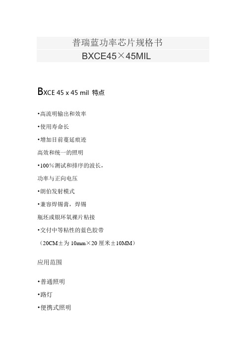
普瑞蓝功率芯片规格书BXCE45×45MILB XCE 45 x 45 mil 特点•高流明输出和效率•使用寿命长•增加目前蔓延痕迹高效和统一的照明•100%测试和排序的波长,功率与正向电压•朗伯发射模式•兼容焊锡膏,焊锡瓶坯或银环氧裸片粘接•交付中等粘性的蓝色胶带(20CM±为10mm×20厘米±10MM)应用范围•普通照明•路灯•便携式照明•建筑照明•定向照明•广域照明•显示背光•数码相机闪光灯•汽车照明•白光LEDLED芯片结构图产品命名方式:B XC E 4 5 4 5 X X X – Y Y – ZBXCE:指定产品系列4545:指定芯片尺寸(45 MIL×45 MIL)XXX:指定主导波长YY:指定辐射功率Z:指定正向电压机械尺寸6。
磁带应存放在垂直方向,而不是水平堆放。
磁带堆叠可以放置过大的压力,对LED的焊盘,导致焊线实力降低。
环保法规:普瑞致力于固态照明市场提供环保产品。
普瑞BXCE4545蓝色功率芯片是符合欧盟对电子设备的指令,即RoHS指令对有害物质的限制。
普瑞不会故意对BXCE4545模具产品添加以下限制材料:铅,汞,镉,六价铬,多溴联苯(PBB)或多溴二苯醚(PBDE)关于普瑞:普瑞是由40亿美金升值到100亿美金的全球照明行业的技术和解决方案的领先开发商和制造商。
总部设在加利福尼亚州利弗莫尔,普瑞是固态照明(SSL)的先驱,发光二极管(LED)技术,扩大市场,拉低了LED照明系统的成本。
普瑞的专利灯源技术取代与整合,固态照明解决方案,使灯具和照明设备制造商,以高的性能和迅速增长的能源效率的白色光(如白炽灯,卤素灯,荧光灯和高强度放电照明)传统技术内部和外部照明市场,包括路灯,商业照明和消费电子应用。
普瑞是与500多个专利申请或授予全球唯一垂直整合的LED制造商和专门开发固态光源照明行业设计的解决方案。
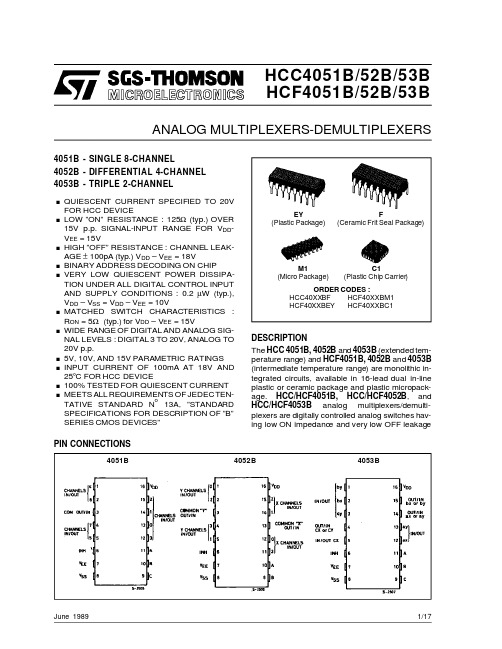
HCF4052中文资料
200
mW
100
mW
– 55 to + 125
°C
– 40 to + 85
°C
Ts tg Storage Temperature
– 65 to + 150
°C
Stresses above those listed under ”Absolute Maximum Ratings” may cause permanent damage to the device. This is a stress rating only and functional operation of the device at these or any other conditions above those indicated in the operational sections of this specification is not implied. Exposure to absolute maximum rating conditions for external periods may affect device r eli abil ity . * All voltage values are referred to VSS pin voltage.
. BINARY ADDRESS DECODING ON CHIP . VERY LOW QUIESCENT POWER DISSIPA-
TION UNDER ALL DIGITAL CONTROL INPUT AND SUPPLY CONDITIONS : 0.2 µW (typ.), VDD – VSS = VDD – VEE = 10V
个人护理单片机
WS2813规格书
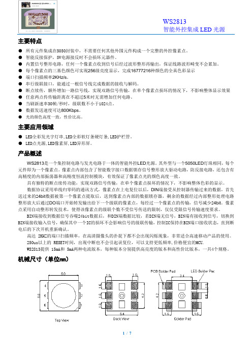
主要特点●所有元件集成在5050封装中,不需要任何其他外围元件构成一个完整的外控像素点。
●智能反接保护,5V电源接反时不会损坏元器件。
●内置信号整形电路,任何一个像素点收到信号后经过波形整形再输出,保证线路波形畸变不会累加。
●每个像素点的三基色颜色可实现256级亮度显示,完成16777216种颜色的全真色彩显示●端口扫描频率2KHz/s。
●串行级联接口,能通过一根信号线完成数据的接收与解码。
●断点续传,额外增加一路信号线,实现双路信号传输,在单个像素点损坏的情况下,不影响整体显示效果●任意两点传传输距离在不超过5米时无需增加任何电路。
●当刷新速率30帧/秒时,级联数不小于1024点。
●数据发送速度可达800Kbps。
●光的颜色高度一致,性价比高。
主要应用领域●LED全彩发光字灯串,LED全彩软灯条硬灯条,LED护栏管。
●LED点光源,LED像素屏,LED异形屏。
产品概述WS2813是一个集控制电路与发光电路于一体的智能外控LED光源。
其外型与一个5050LED灯珠相同,每个元件即为一个像素点。
像素点内部包含了智能数字接口数据锁存信号整形放大驱动电路,防反接电路,还包含有高精度的内部振荡器和高精度恒流控制模块,有效保证了像素点光的颜色高度一致。
具有独特的断点续传功能,实现双路信号传输,在单个像素点损坏的情况下,不影响整体色彩的显示。
数据协议采用单线归零码的通讯方式,像素点在上电复位以后,DIN端接受从控制器传输过来的数据,首先送过来的24bit数据被第一个像素点提取后,送到像素点内部的数据锁存器,剩余的数据经过内部整形处理电路整形放大后通过DO端口开始转发输出给下一个级联的像素点,每经过一个像素点的传输,信号减少24bit。
像素点采用自动整形转发技术,使得该像素点的级联个数不受信号传送的限制,仅仅受限信号传输速度要求。
BIN端接收到数据信号吞噬24bit数据后,和DIN端数据比较,若DIN端无信号,BIN端有接收到信号,切换到BIN端接收输入信号,确保其中一个IC的损坏不会影响信号的级联传输,控制IC保持在BIN端口接收状态,直到断电后的下次开机重新确认。
MRF7S18125BHR3;MRF7S18125BHR5;MRF7S18125BHSR3;MRF7S18125BHSR5;中文规格书,Datasheet资料
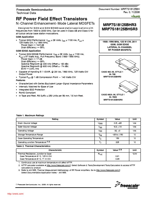
RF Power Field Effect TransistorsN-Channel Enhancement-Mode Lateral MOSFETsDesigned for GSM and GSM EDGE base station applications with frequencies from 1800 to 2000 MHz. Can be used in Class AB and Class C for all typical cellular base station modulations.GSM Application•Typical GSM Performance: V DD = 28 Volts, I DQ = 1100 mA, P out =125Watts CW, f = 1930 MHz.Power Gain — 16.5 dB Drain Efficiency — 55%GSM EDGE Application•Typical GSM EDGE Performance: V DD = 28 Volts, I DQ = 1100 mA,P out = 57 Watts Avg., Full Frequency Band (1930-1990 MHz).Power Gain — 17 dB Drain Efficiency — 39%Spectral Regrowth @ 400 kHz Offset = -60 dBc Spectral Regrowth @ 600 kHz Offset = -74 dBc EVM — 2.6% rms•Capable of Handling 5:1 VSWR, @ 28 Vdc, 1960 MHz, 125 Watts CW Output Power•Typical P out @ 1 dB Compression Point ] 140 Watts CW Features•Characterized with Series Equivalent Large-Signal Impedance Parameters •Internally Matched for Ease of Use •Integrated ESD Protection •RoHS Compliant•In Tape and Reel. R3 Suffix = 250 Units per 56 mm, 13 inch Reel .Table 1. Maximum RatingsRatingSymbol Value Unit Drain-Source Voltage V DSS -0.5, +65Vdc Gate-Source Voltage V GS -6.0, +10Vdc Operating VoltageV DD 32, +0Vdc Storage Temperature Range T stg -65 to +150°C Case Operating Temperature T C 150°C Operating Junction Temperature (1,2)T J225°CTable 2. Thermal CharacteristicsCharacteristicSymbol Value (2,3)Unit Thermal Resistance, Junction to Case Case Temperature 81°C, 125 W CW Case Temperature 81°C, 71 W CWR θJC0.310.35°C/W1.Continuous use at maximum temperature will affect MTTF.2.MTTF calculator available at /rf. Select Software & Tools/Development Tools/Calculators to access MTTF calculators by product.3.Refer to AN1955, Thermal Measurement Methodology of RF Power Amplifiers. Go to /rf. Select Documentation/Application Notes - AN1955.Document Number: MRF7S18125BHRev. 0, 11/2008Freescale Semiconductor Technical DataMRF7S18125BHR3 MRF7S18125BHSR3Table 3. ESD Protection CharacteristicsTest MethodologyClass Human Body Model (per JESD22-A114)1B (Minimum)Machine Model (per EIA/JESD22-A115) A (Minimum)Charge Device Model (per JESD22-C101)IV (Minimum)Table 4. Electrical Characteristics (T C = 25°C unless otherwise noted)CharacteristicSymbolMinTypMaxUnitOff CharacteristicsZero Gate Voltage Drain Leakage Current (V DS = 65 Vdc, V GS = 0 Vdc)I DSS ——10μAdc Zero Gate Voltage Drain Leakage Current (V DS = 28 Vdc, V GS = 0 Vdc)I DSS ——1μAdc Gate-Source Leakage Current (V GS = 5 Vdc, V DS = 0 Vdc)I GSS——1μAdcOn CharacteristicsGate Threshold Voltage(V DS = 10 Vdc, I D = 316 μAdc)V GS(th) 1.2 1.9 2.7Vdc Gate Quiescent Voltage(V DS = 28 Vdc, I D = 1100 mAdc)V GS(Q)— 2.7—Vdc Fixture Gate Quiescent Voltage (1)(V DD = 28 Vdc, I D = 1100 mAdc, Measured in Functional Test)V GG(Q)4 5.37Vdc Drain-Source On-Voltage(V GS = 10 Vdc, I D = 3.16 Adc)V DS(on)0.10.20.3VdcDynamic Characteristics (1)Reverse Transfer Capacitance(V DS = 28 Vdc ± 30 mV(rms)ac @ 1 MHz, V GS = 0 Vdc)C rss — 1.15—pF Output Capacitance(V DS = 28 Vdc ± 30 mV(rms)ac @ 1 MHz, V GS = 0 Vdc)C oss —673—pF Input Capacitance(V DS = 28 Vdc, V GS = 0 Vdc ± 30 mV(rms)ac @ 1 MHz)C iss—309—pFFunctional Tests (In Freescale Test Fixture, 50 ohm system) V DD = 28 Vdc, I DQ = 1100 mA, P out = 125 W CW, f = 1930 MHzPower Gain G ps 1516.518dB Drain Efficiency ηD 5155—%Input Return LossIRL—-12-7dB1.V GG = 2 x V GS(Q). Parameter measured on Freescale Test Fixture, due to resistive divider network on the board. Refer to Test Circuit schematic.2.Part internally matched both on input and output.(continued)MRF7S18125BHR3 MRF7S18125BHSR3Table 4. Electrical Characteristics (T C = 25°C unless otherwise noted) (continued)CharacteristicSymbol Min Typ Max Unit Typical Performances (In Freescale Test Fixture, 50 ohm system) V DD = 28 Vdc, I DQ = 1100 mA, 1930-1990 MHz BandwidthP out @ 1 dB Compression PointP1dB —140—W IMD Symmetry @ 125 W PEP , P out where IMD Third Order Intermodulation ` 30 dBc(Delta IMD Third Order Intermodulation between Upper and Lower Sidebands > 2 dB)IMD sym—10—MHzVBW Resonance Point(IMD Third Order Intermodulation Inflection Point)VBW res —35—MHz Gain Flatness in 60 MHz Bandwidth @ P out = 125 W CW G F — 1.02—dB Average Deviation from Linear Phase in 60 MHz Bandwidth @ P out = 125 W CWΦ— 3.3—°Average Group Delay @ P out = 125 W CW, f = 1960 MHz Delay — 2.49—ns Part-to-Part Insertion Phase Variation @ P out = 125 W CW, f = 1960 MHz, Six Sigma Window ΔΦ— 6.7—°Gain Variation over Temperature (-30°C to +85°C)ΔG —0.016—dB/°C Output Power Variation over Temperature (-30°C to +85°C)ΔP1dB—0.01—dBm/°CTypical GSM EDGE Performances (In Freescale GSM EDGE Test Fixture, 50 ohm system) V DD = 28 Vdc, I DQ = 1100 mA, P out = 57 W Avg., 1930-1990 MHz EDGE Modulation Power Gain G ps —17—dB Drain Efficiency ηD —39—%Error Vector MagnitudeEVM — 2.6—% rms Spectral Regrowth at 400 kHz Offset SR1—-60—dBc Spectral Regrowth at 600 kHz OffsetSR2—-74—dBcMRF7S18125BHR3 MRF7S18125BHSR3Figure 1. MRF7S18125BHR3(HSR3) Test Circuit SchematicZ80.200″ x 0.083″ Microstrip Z9 1.045″ x 0.083″ Microstrip Z100.071″ x 0.083″ Microstrip Z110.227″ x 0.083″ Microstrip Z121.280″ x 0.080″ Microstrip Z13, Z140.760″ x 0.080″ MicrostripPCBTaconic TLX-8 RF35, 0.031″, εr = 2.55Z10.227″ x 0.083″ Microstrip Z20.697″ x 0.083″ Microstrip Z30.618″ x 0.083″ Microstrip Z40.568″ x 1.000″ Microstrip Z50.092″ x 1.000″ Microstrip Z60.095″ x 1.000″ Microstrip Z70.565″ x 1.000″ MicrostripTable 5. MRF7S18125BHR3(HSR3) Test Circuit Component Designations and ValuesPartDescriptionPart NumberManufacturer C11 μF, 50 V Chip Capacitor 12065G105AT2A AVX C2, C3, C4, C5 4.7 μF, 50 V Chip CapacitorsGRM55ER71H475KA01L Murata C6220 μF, 63 V Electrolytic Chip Capacitor 2222 136 68221Vishay C7, C8, C9, C10, C11 6.8 pF Chip Capacitors ATC100B6R8BT500XT ATC C12, C131 pF Chip Capacitors ATC100B1R0BT500XT ATC C14, C15, C16, C17, C180.2 pF Chip Capacitors ATC100B0R2BT500XT ATC R1, R210 k Ω, 1/4 W Chip Resistors CRCW12061001FKEA Vishay R310 Ω, 1/4 W Chip ResistorCRCW120610R1FKEAVishayFigure 2. MRF7S18125BHR3(HSR3) Test Circuit Component LayoutMRF7S18125BHR3 MRF7S18125BHSR3MRF7S18125BHR3 MRF7S18125BHSR3TYPICAL CHARACTERISTICSP out , OUTPUT POWER (WATTS) CW100131817151410300Figure 5. Power Gain versus Output PowerG p s , P O W E R G A I N (d B )161000.110TWO−TONE SPACING (MHz)Figure 6. Intermodulation Distortion Productsversus Two-Tone Spacing1MRF7S18125BHR3 MRF7S18125BHSR3TYPICAL CHARACTERISTICS60P in , INPUT POWER (dBm)53515034373552363839Figure 7. Pulsed CW Output Power versusInput PowerP o u t , O U T P U T P O W E R (d B c )54555657404142433001815103020P out , OUTPUT POWER (WATTS) CWFigure 8. Power Gain and Drain Efficiencyversus Output PowerG p s , P O W E R G A I N (d B )17.51710040585916.51615.51514.51413.51325354550556065E V M , E R R O R V E C T O R M A G N I T U D E (% r m s )063142)P out , OUTPUT POWER (WATTS)20Figure 11. Spectral Regrowth at 400 kHzversus Output Power S P E C T R A L R E G R O W T H @ 400 k H z (d B c )4020060801001201401601803350P out , OUTPUT POWER (WATTS)20Figure 12. Spectral Regrowth at 600 kHzversus Output Power402006080100120140160180ηD , D R A I N E F F I C I E N C Y (%)MRF7S18125BHR3 MRF7S18125BHSR3TYPICAL CHARACTERISTICSP out , OUTPUT POWER (WATTS) AVG.500122420160101820604030010Figure 13. EVM and Drain Efficiency versusOutput PowerE V M , E R R O R V E C T O R M A G N I T U D E (% r m s )141918171615f, FREQUENCY (MHz)Figure 14. Power Gain versus FrequencyG p s , P O W E R G A I N (d B )41005025010990T J , JUNCTION TEMPERATURE (°C)Figure 15. MTTF versus Junction TemperatureThis above graph displays calculated MTTF in hours when the device is operated at V DD = 28 Vdc, P out = 125 W CW, and ηD = 55%.MTTF calculator available at /rf. Select Software & Tools/Development Tools/Calculators to access MTTF calculators by product.107106105110130150170190M T T F (H O U R S )2102301081930194019501960197019801990ηD , D R A I N E F F I C I E N C Y (%)MRF7S18125BHR3 MRF7S18125BHSR3GSM TEST SIGNALFigure 16. EDGE Spectrum−10−20−30−40−50−60−70−80−90−100200 kHzSpan 2 MHzCenter 1.96 GHz−110(d B )MRF7S18125BHR3 MRF7S18125BHSR3Z o = 5ΩZ loadZ sourcef = 2040MHzf = 1880MHzf = 1880MHzf = 2040MHzV DD = 28 Vdc, I DQ = 1100 mA, P out = 125 W CWfMHzZ sourceWZ loadW1880 1.31 - j3.61 1.32 - j3.061900 1.25 - j3.061.30 - j2.921920 1.21 - j3.30 1.28 - j2.791940 1.17 - j3.17 1.26 - j2.671960 1.13 - j3.06 1.23 - j2.551980 1.10 - j2.92 1.20 - j2.422000 1.06 - j2.83 1.18 - j2.3020200.99 - j2.75 1.16 - j2.1820400.91 - j2.66 1.12 - j2.07Z source=Test circuit impedance as measured fromgate to ground.Z load=Test circuit impedance as measuredfrom drain to ground.Figure 17. Series Equivalent Source and Load ImpedanceZ source Z loadOutputMatchingNetwork分销商库存信息:FREESCALEMRF7S18125BHR3MRF7S18125BHR5MRF7S18125BHSR3 MRF7S18125BHSR5。
HCF4060M013TR,HCF4060BEY, 规格书,Datasheet 资料
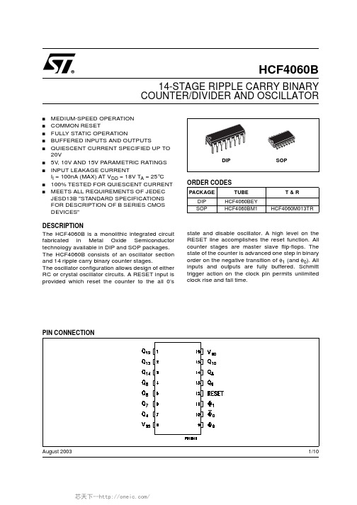
1/10August 2003s MEDIUM-SPEED OPERATION s COMMON RESETs FULLY STATIC OPERATIONs BUFFERED INPUTS AND OUTPUTSsQUIESCENT CURRENT SPECIFIED UP TO 20Vs 5V,10V AND 15V PARAMETRIC RATINGS sINPUT LEAKAGE CURRENTI I =100nA (MAX)AT V DD =18V T A =25°C s 100%TESTED FOR QUIESCENT CURRENT sMEETS ALL REQUIREMENTS OF JEDEC JESD13B "STANDARD SPECIFICATIONS FOR DESCRIPTION OF B SERIES CMOS DEVICES"DESCRIPTIONThe HCF4060B is a monolithic integrated circuit fabricated in Metal Oxide Semiconductor technology available in DIP and SOP packages.The HCF4060B consists of an oscillator section and 14ripple carry binary counter stages.The oscillator configuration allows design of either RC or crystal oscillator circuits.A RESET input is provided which reset the counter to the all 0’sstate and disable oscillator.A high level on the RESET line accomplishes the reset function.All counter stages are master slave flip-flops.The state of the counter is advanced one step in binary order on the negative transition of φ1(and φ0).All inputs and outputs are fully buffered.Schmitt trigger action on the clock pin permits unlimited clock rise and fall time.HCF4060B14-STAGE RIPPLE CARRY BINARY COUNTER/DIVIDER ANDOSCILLATORORDER CODESPACKAGE TUBE T &R DIP HCF4060BEY SOPHCF4060BM1HCF4060M013TRHCF4060B2/10INPUT EQUIVALENT CIRCUITPIN DESCRIPTIONFUNCTIONAL DIAGRAMLOGICDIAGRAMPIN No SYMBOLNAME AND FUNCTION1,2,3,4,5,6,7,13,14,15Q 12,Q 13,Q 14,Q 6,Q 5,Q 7,Q 4,Q 9,Q 8,Q 10Outputs 9,10,11Φ0,Φ0,Φ1Oscillator Input 12RESET Reset8V SS Negative Supply Volt-age16V DDPositive Supply Volt-ageHCF4060B3/10ABSOLUTE MAXIMUM RATINGSAbsolute Maximum Ratings are those values beyond which damage to the device may occur.Functional operation under these conditions is not implied.All voltage values are referred to V SS pin voltage.RECOMMENDED OPERATING CONDITIONSSymbol ParameterValue Unit V DD Supply Voltage -0.5to +22V V I DC Input Voltage -0.5to V DD +0.5V I I DC Input Current±10mA P D Power Dissipation per Package200mW Power Dissipation per Output Transistor 100mW T op Operating Temperature -55to +125°C T stgStorage Temperature-65to +150°CSymbol ParameterValue Unit V DD Supply Voltage 3to 20V V I Input Voltage0to V DD V T opOperating Temperature-55to 125°CHCF4060B4/10DC SPECIFICATIONSThe Noise Margin for both "1"and "0"level is:1V min.with V DD =5V,2V min.with V DD =10V,2.5V min.with V DD =15VSymbolParameterTest ConditionValue UnitV I (V)V O (V)|I O |(µA)V DD (V)T A =25°C -40to 85°C -55to 125°C Min.Typ.Max.Min.Max.Min.Max.I LQuiescent Current0/550.0455150µA0/10100.0410103000/15150.0420206000/20200.081001003000V OHHigh Level Output Voltage0/5<15 4.95 4.95 4.95V0/10<1109.959.959.950/15<11514.9514.9514.95V OLLow Level Output Voltage 5/0<150.050.050.05V10/0<1100.050.050.0515/0<1150.050.050.05V IHHigh Level Input Voltage 0.5/4.5<15 3.5 3.5 3.5V1/9<1107771.5/13.5<115111111V ILLow Level Input Voltage 4.5/0.5<15 1.5 1.5 1.5V9/1<11033313.5/1.5<115444I OHOutput Drive Current0/5 2.5<15-1.36-3.2-1.15-1.1mA0/5 4.6<15-0.44-1-0.36-0.360/109.5<110-1.1-2.6-0.9-0.90/1513.5<115-3.0-6.8-2.4-2.4I OLOutput Sink Current0/50.4<150.4410.360.36mA 0/100.5<110 1.1 2.60.90.90/15 1.5<115 3.06.8 2.42.4I I Input Leakage Current0/18Any Input 18±10-5±0.3±0.3±1µA C IInput CapacitanceAny Input57.5pFHCF4060B5/10DYNAMIC ELECTRICAL CHARACTERISTICS (T amb =25°C,C L =50pF,R L =200K Ω,t r =t f =20ns)(*)Typical temperature coefficient for all V DD values is 0.3%/°C,all input rise and fall times=20ns.(**)RC Oscillator applications are not recommended at supply voltages below 7V for R X <50K ΩSymbolParameterTest ConditionValue (*)UnitV DD (V)Min.Typ.Max.t TLH t THL Output Transition Time5100200ns 1050100154080t PLH t PHL Propagation Delay Time (φto Q 4out)5370740ns1015030015100200t PLH t PHL Propagation Delay Time(Q n to Q n+1)5100200ns1050100154080t WInput Pulse Width5f =100KHz 50100ns102040151530t r t fInput Pulse Rise and Fall Time5Unlimited µs1015f maxMaximum Clock Input Frequency5 3.57MHz10816151224RESET OPERATION t PHL Propagation Delay Time5180360ns10801601550100t WInput Pulse Width560120ns103060152040RC OPERATIONVariation of Frequency (Unit-to-Unit)5C X =200pF,R S =560K Ω, R X =50K Ω1821.525KHz102023261521.12427Variation of Frequency With Voltage Change (Same Unit)5to 10C X =200pF,R S =560K Ω, R X =50K Ω2KHz10to 151R X5C X =10µF 20M Ω10C X =50µF 2015C X =10µF 10C X5R X =500K Ω1000µF 10R X =300K Ω5015R X =300K Ω50Maximum Oscillator Frequency (**)10R X =5K Ω, C X =15pF530650810KHz 15690800940HCF4060B6/10DETAIL OF TYPICAL FLIP-FLOP STAGETYPICAL RC OSCILLATOR CIRCUITTYPICAL CRYSTAL OSCILLATORCIRCUITHCF4060BInformation furnished is believed to be accurate and reliable. However, STMicroelectronics assumes no responsibility for the consequences of use of such information nor for any infringement of patents or other rights of third parties which may result from its use. No license is granted by implication or otherwise under any patent or patent rights of STMicroelectronics. Specifications mentioned in this publication are subject to change without notice. This publication supersedes and replaces all information previously supplied. STMicroelectronics products are not authorized for use as critical components in life support devices or systems without express written approval of STMicroelectronics.© The ST logo is a registered trademark of STMicroelectronics© 2003 STMicroelectronics - Printed in Italy - All Rights ReservedSTMicroelectronics GROUP OF COMPANIESAustralia - Brazil - Canada - China - Finland - France - Germany - Hong Kong - India - Israel - Italy - Japan - Malaysia - Malta - Morocco Singapore - Spain - Sweden - Switzerland - United Kingdom - United States.© 10/10。
BXCD4545_revG BXCD4545 Datasheet
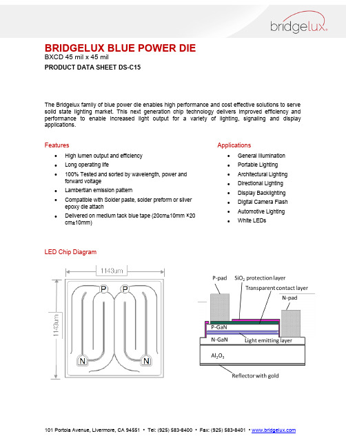
BRIDGELUX BLUE POWER DIEBXCD 45 mil x 45 milPRODUCT DATA SHEET DS-C15The Bridgelux family of blue power die enables high performance and cost effective solutions to serve solid state lighting market. This next generation chip technology delivers improved efficiency and performance to enable increased light output for a variety of lighting, signaling and display applications.Features∙High lumen output and efficiency∙Long operating life∙100% Tested and sorted by wavelength, power and forward voltage∙Lambertian emission pattern∙Compatible with Solder paste, solder preform or silver epoxy die attach∙Delivered on medium tack blue tape (20cm±10mm ×20 cm±10mm) Applications∙General Illumination∙Portable Lighting∙Architectural Lighting∙Directional Lighting∙Display Backlighting∙Digital Camera Flash∙Automotive Lighting∙White LEDsLED Chip DiagramBRIDGELUX BLUE POWER DIEBXCD 45 mil x 45 milProduct NomenclatureB XCD 4545 X X X – Y – ZWhere:BXCD: Designates product family4545: Designates die size (45 mil x 45 mil)XXX: Designates dominant wavelength binY: Designates radiometric power binZ: Designates forward voltage binPart Numbering and Bin DefinitionsBridgelux LED chips are sorted into the brightness and dominant wavelength bins shown below at I f = 350 mA. Each blue tape contains die from only one brightness bin and one wavelength bin.The forward voltage bins are 3.0-3.1V (A1), 3.1-3.2V (A2), 3.2-3.3 V (B1), and 3.3-3.4 V (B2). The typical forward voltage is 3.2 V and the maximum forward voltage (V f max) = 3.4 V.Dominant WavelengthPower Bin H1(420 – 440 mW)Power Bin H2(440 – 460 mW)Power Bin J1(460 – 480 mW)450 to 452.5nm BXCD4545450-H1-z BXCD4545450-H2-z BXCD4545450-J1-z 452.5 to 455nm BXCD4545452-H1-z BXCD4545452-H2-z BXCD4545452-J1-z 455 to 457.5nm BXCD4545455-H1-z BXCD4545455-H2-z BXCD4545455-J1-z 457.5 to 460nm BXCD4545457-H1-z BXCD4545457-H2-z BXCD4545457-J1-zNote:z = “A1” for Vf bin of 3.0-3.1V; z = “A2” for Vf bin of 3.1-3.2V; z = “B1” for Vf bin of 3.2-3.3V; z = “B2” for Vf bin of 3.3-3.4VBRIDGELUX Blue Power DieBXCD 45 mil x 45 milMechanical DimensionsAbsolute Maximum RatingsNotes:1. Maximum drive current depends on junction temperature, die attach methods/materials, and lifetimerequirements of the application.2. Bridgelux LED chips are Class 1 ESD sensitive.3. The typical spectra half-width of the BXCD4545 blue power die is < 25 nm.4. Please consult the Bridgelux technical support team for information on how to optimize the light output ofour chips in your package.5. Brightness values are measured in an integrating sphere using gold plated TO39 headers withoutencapsulation.6. Tapes should be stored in a vertical orientation, not horizontally stacked. Stacking of tapes can placeexcessive pressure on the bond pads of the LED, resulting in reduced wire bonding strength.BRIDGELUX BLUE POWER DIEBXCD 45 mil x 45 milEnvironmental ComplianceBridgelux is committed to providing environmentally friendly products to the solid state lighting market. Bridgelux BXCD4545 blue power die are compliant to the European Union directives on the restriction of hazardous substances in electronic equipment, namely the RoHS directive. Bridgelux will not intentionally add the following restricted materials to BXCD4545 die products: lead, mercury, cadmium, hexavalent chromium, polybrominated biphenyls (PBB) or polybrominated diphenyl ethers (PBDE).Performance vs. CurrentThe following curves represent typical performance of the BXCD4545 blue power die. Actual performance will vary slightly for different power, dominant wavelength and Vf bins.Figure 1: Relative Luminous Intensity vs. Forward Current (T j = 25°C)Figure 2: Forward Current vs. Forward Voltage (T j = 25°C)Performance vs. Junction TemperatureThe following curves represent typical performance of the BXCD4545 blue power die. Actual performance will vary slightly for different power, dominant wavelength and Vf bins.Figure 3: Forward Voltage Shift vs. Junction TemperatureFigure 4: Relative Light Intensity vs. Junction TemperatureWavelength ShiftThe following curves represent typical performance of the BXCD4545 blue power die. Actual performance will vary slightly for different power, dominant wavelength and Vf bins.Figure 5: Wavelength Shift vs. Junction TemperatureTypical Radiation PatternFigure 7: Typical Radiation Pattern (350 mA Operation)Current De-rating CurvesFigure 8: Current Derating Curve vs. Ambient Temperature (derating based on T j max 150°C)About BridgeluxBridgelux is a leading developer and manufacturer of technologies and solutions transforming the $40 billion global lighting industry into a $100 billion market opportunity. Based in Livermore, California, Bridgelux is a pioneer in solid state lighting (SSL), expanding the market for light emitting diode (LED) technologies by driving down the cost of LED lighting systems. Bridgelux’s patented light source technology replaces traditional technologies (such as incandescent, halogen, fluorescent and high intensity discharge lighting) with integrated, solid state lighting solutions that enable lamp and luminaire manufacturers to provide high performance and energy-efficient white light for the rapidly growing interior and exterior lighting markets, including street lights, commercial lighting and consumer applications. Bridgelux is the only vertically integrated LED manufacturer and developer of solid-state light sources that designs its solutions specifically for the lighting industry.For more information about the company, please visit © 2014 Bridgelux, Inc. All rights reserved. Product specifications are subject to change without notice.。
DK5V45R25 规格书参数
DK5V45R25 Rev: V0.1
第5页共9页
201 6/11 /4
DK5V45R25 同步整流芯片
测试仪器: 1.WT3100功率计 2.PRODIGIT 3311电子负载 3.FLUKE 17B+
用 DK1208的5V2A DEMO 板进行对比测试,检测板端电压进行效率对比。测试参数见表格:
V
4.2
V
3.5
V
8
V
100 KHz
-25
150 ℃
正向整流应用
DK5V45R25 Rev: V0.1
第3页共9页
201 6/11 /4
DK5V45R25
反向整流应用
同步整流芯片
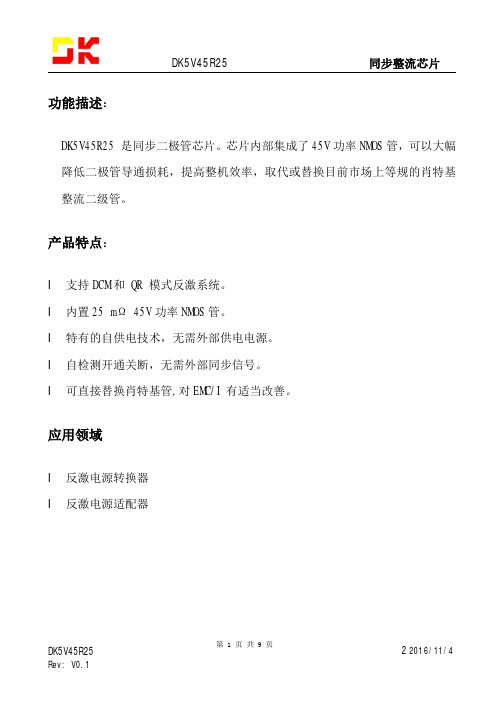
功能描述
自供电
DK5V45R25 内置储能电容和自供电线路,可以实现芯片和功率 MOS 管驱动需求,无需外 接电源 。刘先生/贰柒陆叁陆叁贰肆捌/壹伍玖玖玖伍柒陆贰肆玖
4.请注意 SM-7旁边的两个金属测试点,不能和其它导电的线路连接。
DK5V45R25 Rev: V0.1
第7页共9页
201 6/11 /4
DK5V45R25
封装尺寸:
同步整流芯片
焊盘参考尺寸 1:
DK5V45R25 Rev: V0.1
第8页共9页
201 6/11 /4
DK5V45R25
编带包装:5K/盘
产品特点:
l 支持 DCM 和 QR 模式反激系统。 l 内置 25 mΩ 45V 功率 NMOS 管。 l 特有的自供电技术,无需外部供电电源。 l 自检测开通关断,无需外部同步信号。 l 可直接替换肖特基管,对 EMC/I 有适当改善。
应用领域
l 反激电源转换器 l 反激电源适配器
CRT型号配件库存
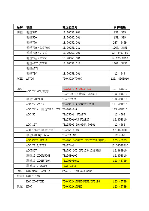
BSC24-N2374S 美格99P 美格XJ700T 菲利普 105G(裕安) 107S,107S51 107s67/107S66 107S(17C2622H)普平 107T(荣欣) (联想)LXH-769 (联想)LXH-GJ769F4 三星 三星450B 三星550B 三星510N 三星743DF/763DF 三星750S 753DF 三星 三星 三星 三星788DF 793DF 三星795MB 三星793DF 三星997MB 三星988MB+ HP TCL P9009 19寸 TCL M1502 TCL MF767 TCL MF786 方正 海洋 方向 海信 ? CM787Z 海洋 T171 海信HS-1728R HY现代 HY775 730-302-797N LCE CF1033A FEA888 LCE CF2091 FM-1077/FPH0213/2091 AT2097/20B AT2097 / LCE CF1880 730-302-P8NS 79A774 FKG-15A006 FQA-15A001 FQA-15A001 FQM-17B002/FQM-17B015/ PQB-17A001 FEA831 FSA0188 LCE CF1781 FQM-17B021 FQM-17A011 FQM-17A012 FQM-19A007 FQM-19A005 BH26-00205A Y268109B BSM35-3221 37SC25M0-2510X 25-0208M 730-302-P6SE BSM76-3709 (可以用730-302-770VC代换) BSC26-1461 BSC26-1453 BSM75-3707 BSM75-3708C BSM75-3709 12.35.46810 12345. 67810 1267.345810 12. 3489. 56 123.568910 BSM64-3803 1478. 35910 139.24678 139.24678 1478. 35910 14.27.358910 123.45789 12.34568910 1279. 345 12.36.579 12.36.579 12.3610.4579 12. 36. 4579 12.345679 12.345679 12.34610.579 12.410.579 12.410.579 12.35.489.610 12.46.579 12.46.579 12.3579.46 12.5681
F2454数码管规格书
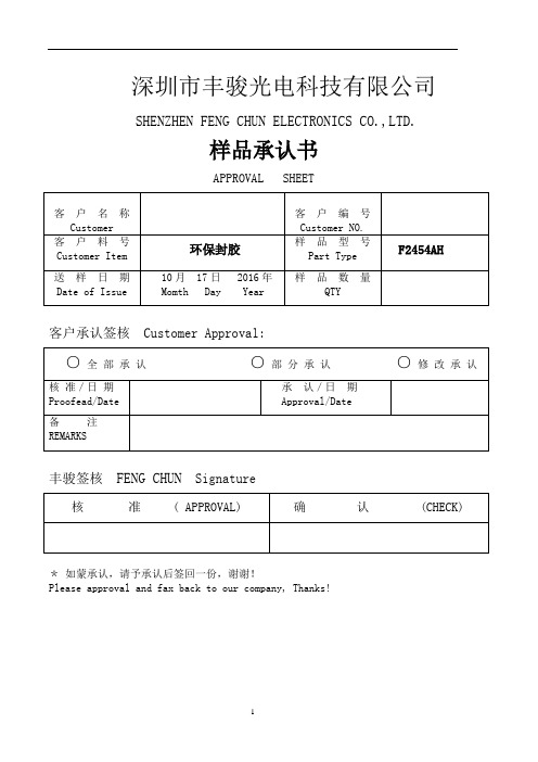
深圳市丰骏光电科技有限公司SHENZHEN FENG CHUN ELECTRONICS CO.,LTD.样品承认书APPROVAL SHEET客户名称Customer 客户编号Customer NO.客户料号Customer Item 环保封胶样品型号Part TypeF2454AH送样日期Date of Issue 10月17日 2016年Momth Day Year样品数量QTY客户承认签核Customer Approval:○全部承认○部分承认○修改承认核准/日期Proofead/Date 承认/日期Approval/Date备注REMARKS丰骏签核FENG CHUN Signature核准 ( APPROVAL) 确认 (CHECK)*如蒙承认,请予承认后签回一份,谢谢!Please approval and fax back to our company, Thanks!LED显示屏产品说明书SPECIFICATION OF LED DISPLAY客户确认:——————型号(PART NO.):F2454AH用途Aplication:外型尺寸Outer Dimension长:Pancl Length:19.8mm宽:Pancl Width:10mm厚:Pancl Thickness:5mm发光颜色:Emitted Color 红电极间距:Lead Pitch 2.54mm一、极限参数:(Absolute Masimum Ratings)项目Item符号Symbol极限值(Max)单位Unit 红色功耗(Power Dissipation)Pd 57 mW 脉冲电流(Peak Forward Current)Ifp 80 mA 直流电流(Continuous Forward Current)Ifm 20 mA 反向电压(Reveerse V oltage)VR 5 V 工作温度(Operating Temperature Range)Topr -40~+80 ℃储藏温度(Storage Temperature Range)Tstg -40~+85 ℃静电电压(STATIC V oltage)Var ------ ------ ------ V二、光电特性(Optical-Electrical Characteristic)(1)红色(RED)参数(Parameter)测试条件TEST CONDITING)符号SymbolsMin Type Max 单位Unit发光强度(Luminous Intemsity)If=20mA IV 55 60 70 Mcd 正向电压(Forward Voltage)If=20mA VF 1.9 2.0 2.03 V 反向电流(Revbrse Current)VR=5V IR - - 100 uA 波长(Peak Wavelength) If=20mA λp620 621 623 nm 带宽(Spectral Bandwidth) If=20mA △λ- 5 nm 查看角度(View Angle) If=20mA 201/2- 60 Deg三、F2454AH Package Dimensions And Internal Circuit Diagram(1)F2454AH PACKAGE DIMENSION 结构图(2)F2454AH INTERNAL CIRCUIT DIAGRAM 电路图四、保存和焊接条件(Storage & Soldering Conditions):1、注意保存,保存条件不好时,会降低膜片与反射壳(导光板)的粘附力。
- 1、下载文档前请自行甄别文档内容的完整性,平台不提供额外的编辑、内容补充、找答案等附加服务。
- 2、"仅部分预览"的文档,不可在线预览部分如存在完整性等问题,可反馈申请退款(可完整预览的文档不适用该条件!)。
- 3、如文档侵犯您的权益,请联系客服反馈,我们会尽快为您处理(人工客服工作时间:9:00-18:30)。
1/10September 2001sEXPANDABLE WITH MULTIPLE PACKAGES s STANDARDIZED SYMMETRICAL OUTPUT CHARACTERISTICSs QUIESCENT CURRENT SPECIFIED UP TO 20V s 5V, 10V AND 15V PARAMETRIC RATINGS s INPUT LEAKAGE CURRENTI I = 100nA (MAX) AT V DD = 18V T A = 25°C s 100% TESTED FOR QUIESCENT CURRENT s MEETS ALL REQUIREMENTS OF JEDEC JESD13B " STANDARD SPECIFICATIONS FOR DESCRIPTION OF B SERIES CMOS DEVICES"DESCRIPTIONThe HCF4555B is a monolithic integrated circuit fabricated in Metal Oxide Semiconductor technology available in DIP and SOP packages. The HCF4555B is a dual 1 of 4 decoder/demultiplexer. Each decoder has two select inputs (A and B), an Enable input (E), and four mutuallyexclusive outputs. On the HCF4555B the outputs are high on select. When the Enable input is high,the outputs is low regardless of the state of the select inputs A and B.HCF4555BDUAL BINARY TO 1 OF 4 DECODER/DEMULTIPLEXEROUTPUT HIGH ON SELECTPIN CONNECTIONORDER CODESPACKAGE TUBE T & R DIP HCF4555BEY SOPHCF4555BM1HCF4555M013TRHCF4555B2/10IINPUT EQUIVALENT CIRCUITPIN DESCRIPTIONTRUTH TABLEX : Don’t CareFUNCTIONAL DIAGRAMPIN No SYMBOL NAME AND FUNCTION 2, 3A, B Select Inputs (1/2 of dual)1E Enable Input (1/2 of dual)4, 5, 6, 7Q0 to Q3Outputs (1/2 of dual)14, 13A, B Select Inputs (1/2 of dual)15E Enable Input (1/2 of dual)12, 11, 10, 9Q0 to Q3Outputs (1/2 of dual)8V SS Negative Supply Voltage 16V DDPositive Supply VoltageINPUTS ENABLE SELECT OUTPUTSE B A Q3Q2Q1Q0L L L L L L H L L H L L H L L H L L H L L L H H H L L L HXXLLLLHCF4555B3/10LOGIC DIAGRAMABSOLUTE MAXIMUM RATINGSAbsolute Maximum Ratings are those values beyond which damage to the device may occur. Functional operation under these conditions is not implied.All voltage values are referred to V SS pin voltage.RECOMMENDED OPERATING CONDITIONSSymbol ParameterValue Unit V DD Supply Voltage -0.5 to +22V V I DC Input Voltage -0.5 to V DD + 0.5V I I DC Input Current± 10mA P D Power Dissipation per Package200mW Power Dissipation per Output Transistor 100mW T op Operating Temperature -55 to +125°C T stgStorage Temperature-65 to +150°CSymbol ParameterValue Unit V DD Supply Voltage 3 to 20V V I Input Voltage0 to V DD V T opOperating Temperature-55 to 125°CHCF4555B4/10DC SPECIFICATIONSThe Noise Margin for both "1" and "0" level is: 1V min. with V DD =5V, 2V min. with V DD =10V, 2.5V min. with V DD =15VDYNAMIC ELECTRICAL CHARACTERISTICS (T amb = 25°C, C L = 50pF, R L = 200K Ω, t r = t f = 20 ns)(*) Typical temperature coefficient for all V DD value is 0.3 %/°C.SymbolParameterTest ConditionValue UnitV I (V)V O (V)|I O |(µA)V DD (V)T A = 25°C -40 to 85°C -55 to 125°C Min.Typ.Max.Min.Max.Min.Max.I LQuiescent Current0/550.045150150µA0/10100.0410*******/15150.04206006000/20200.0810030003000V OHHigh Level Output Voltage0/5<15 4.95 4.95 4.95V0/10<1109.959.959.950/15<11514.9514.9514.95V OLLow Level Output Voltage5/0<150.050.050.05V10/0<1100.050.050.0515/0<1150.050.050.05V IHHigh Level Input Voltage 0.5/4.5<15 3.5 3.5 3.5V1/9<1107771.5/13.5<115111111V ILLow Level Input Voltage 4.5/0.5<15 1.5 1.5 1.5V9/1<11033313.5/1.5<115444I OHOutput Drive Current0/5 2.5<15-1.36-3.2-1.1-1.1mA0/5 4.6<15-0.44-1-0.36-0.360/109.5<110-1.1-2.6-0.9-0.90/1513.5<115-3.0-6.8-2.4-2.4I OLOutput Sink Current0/50.4<150.4410.360.36mA 0/100.5<110 1.1 2.60.90.90/15 1.5<115 3.06.8 2.42.4I I Input Leakage Current0/18Any Input 18±10-5±0.1±1±1µA C IInput CapacitanceAny Input57.5pFSymbolParameterTest ConditionValue (*)UnitV DD (V)Min.Typ.Max.t PLH t PHL Propagation Delay Time5 A or B Input to any Output220440ns 10951901570140t PLH t PHL Propagation Delay Time5 E Input to any Output 200400ns10851701565130t TLH t THL Transition Time5100200ns1050100154080HCF4555B TYPICAL APPLICATIONS1 OF 4 LINE DATA DEMULTIPLEXER USING HCF4555B1 OF 8 DECODER USING HCF4555B5/10HCF4555B6/101 OF 16 DECODER USING HCF4555B AND HCF4556BTEST CIRCUITL R L = 200K ΩR T = Z OUT of pulse generator (typically 50Ω)HCF4555B WAVEFORM 1 : PROPAGATION DELAY TIMES (INPUT TO Q3 OUTPUT) (f=1MHz; 50% duty cycle)WAVEFORM 2 : PROPAGATION DELAY TIMES (E INPUT TO Q3 OUTPUT)(f=1MHz; 50% duty cycle)7/10HCF4555BInformation furnished is believed to be accurate and reliable. However, STMicroelectronics assumes no responsibility for the consequences of use of such information nor for any infringement of patents or other rights of third parties which may result from its use. No license is granted by implication or otherwise under any patent or patent rights of STMicroelectronics. Specifications mentioned in this publication are subject to change without notice. This publication supersedes and replaces all information previously supplied. STMicroelectronics products are not authorized for use as critical components in life support devices or systems without express written approval of STMicroelectronics.© The ST logo is a registered trademark of STMicroelectronics© 2001 STMicroelectronics - Printed in Italy - All Rights ReservedSTMicroelectronics GROUP OF COMPANIESAustralia - Brazil - China - Finland - France - Germany - Hong Kong - India - Italy - Japan - Malaysia - Malta - MoroccoSingapore - Spain - Sweden - Switzerland - United Kingdom© 10/10。
