专用集成电路设计中科院段成华
中科院数字集成系统设计(段成华)作业答案
Assignment 1:1.ITRS:International Technology Roadmap for Semiconductors 中文:国际半导体技术蓝图Gate-Equivalent:gate equivalent (GE) stands for a unit of measure which allows to specify manufacturing-technology-independent complexity of digital electronic circuitsTechnology Nodes:A technology node is defined as the ground rules of a process governed by the smallest feature printed in a repetitive arrayFeature size: The size of the elements on a chip, which is designated by the DRAM half pitch(动态随机存取存储器半间距). The smallest feature size is generally smaller than the feature size for a technology generation (technology node).Behavioral representation: representing a design as a Black Box and describe its outputs in term of its input and time行为表示:表示一种设计,这个设计只描述它们的输入和输出以及具体的时序结构。
Structural representation: A Black Box is represented as a set of components and connections结构表示:表示一种设计结构,其中的结构是由一系列的组件和连线构成Geometrical representation: it ignores what the design is supposed to do and binds its structure in space or to silicon.It entails the specification of all geometric patterns defining the physical layout of the chip, as well as their position几何表示:在这个结构中,不注意设计的目的是什么,只关心具体的几何实现,这种设计结构通过定义在芯片上的所有器件的物理布局甚至是具体位置来实现所有的几何设计。
中国科学院大学 段成华 VLSI 超大规模集成电路 期末复习笔记(1到10章)

MOS 管 耗尽区电荷以及宽度
阈值电压的定义,饱和区线性区等阶段的电流
阈值电压:强反型发生时
饱和区: 与 Vgs-Vt 平方成正比
线性区:
ID
n
(VGS
VT
)VDS
VDS 2
2
Vds 较小时忽略平方项,就是线性关系
沟调效应
增加 Vds 会使漏结的耗尽区变大,缩小了有效沟道长度。 影响为:Vds 会增大 ID
Vdd Vdd 0 'Supply' VgspVdd gatep dc='Supply' Vgsngaten Gnd dc='Supply'
.dc Vgsp0 'Supply' 'Supply/20' .dc Vgsn0 'Supply' 'Supply/20'
.print dc I1(mp) .print dc I1(mn)
* Set TSMC 0.18um library
*.model pch PMOS level=49 version = 3.1 *.model nch NMOS level=49 version = 3.1
.options list node post measout * Option List: Prints a list of netlist elements, node connections, and values for components, voltage and current sources, parameters, and more. * Option Node: Prints a node cross-reference table. * Option Post: Saves simulation results for viewing by an interactive waveform viewer. * Option Measout: Outputs .MEASURE statement values and sweep parameters into an ASCII file.
中科院_段成华_专用集成电路设计_作业2详解
中科院_段成华_专用集成电路设计_作业2详解Assignment 21. Give a descriptive definition for each of the following terms.(1)Starting substrateCrystalline silicon wafers(2)Active regionThe region between saturation and cutoff used for linear amplification(3)LOCOS processShort for LOCal Oxidation of Silicon process,a microfabrication process where silicon dioxide is formed in selected areas on a silicon wafer having the Si-SiO2 interface ata lower point than the rest of the silicon surface(4)Field oxide layerIt is a thin layer of Silicon dioxide present beneath the polysilicon gate that serves as dielectric for gate oxide capacitance(5)Shallow Trench Isolation (STI)An integrated circuit feature which prevents electrical current leakage between adjacent semiconductor device components(6)Positive resist and negative resistPositive resist:a type of photoresist in which the portion of the photoresist that is exposed to light becomes soluble to the photoresist developerNegative resist:a type of photoresist in which the portion of the photoresist that is exposed to light becomes insoluble to the photoresist developer(7)SputteringA process whereby atoms are ejected from a solid target material due to bombardment of the target by energetic particles(8)Reactive ion etchingAn etching technology that High-energy ions from the plasma, generated under low pressure (vacuum) by an electromagnetic field, attack the wafer surface and react with it (9)Strong inversion layerSemiconductor surface minority carrier concentration is equal to the majority of thebody of the carrier concentration, the potential of the formation of a surface of the semiconductor surface is approximately a constant value, the depletion layer charge and depletion layer thickness maxima state called strong inversion layer(10) Threshold voltage of MOS transistorThe voltage at which there are sufficient electrons in the inversion layer to make a low resistance conducting path between the MOSFET source and drain2. P - type well in a 250nm technology has the doping concentration N A = 1015atoms cm -3. Find the limiting value of depletion-layer width w d and the total charge Q d contained in the depletion region. Use /26kT q mV =at 300K; 011.7;si εε=1408.8510/.F cm ε-=? 解:22ln 0.58i FP A n kT V q N φ?===870d w nm ===821.410d A d Q qN w C cm -====-?3. As the value of the drain-source voltage is further increased, the assumption that the channel voltage is larger than the threshold all along the channel ceases to hold. This happens when V GS - V (x ) <="" disappears="" drain="" exists="" explain="" has="" i="" in="" induced="" instead="" is="" keep="" no="" of="" off="" or="" p="" pinched="" please="" point,="" region="" remains="" saturates).="" t="" that="" the="" vicinity="" while="" why="" zero="" zero,="">Reference:[1] James D. Plummer, et al., “Chapter 2 Modern CMOS Technology,”Silicon VLSI Technology:Fundamentals, Practice and Modeling, Prentice Hall, 2000. (Available at our course website)在V DS较小时,它对I D的影响应从两个角度来分析:一方面V DS增加时,沟道的电场强度增大,I D随着增加;另一方面,随着V DS的增加,沟道的不均匀性增大,即沟道电阻增加,I D应该下降,但是在V DS较小时,沟道的不均匀性不明显,在漏极附近的区域内沟道仍然较宽,即V DS对沟道电阻影响不大,故I D随V DS增加而几乎呈线性地增加。
中科院_段成华_数字集成系统设计_作业2详解

Assignment 2Question 1(1) propagation timet PD指输入信号从器件某脚输入后到组合逻辑输出有效时所需的时间。
(2) transition timet TD指输入信号从开始输入到输出有效时所需的时间。
(3) setup time t SU指触发器的时钟的上升沿到来之前,触发器的输入信号到达稳定状态所需的时间。
(4) hold time t HD指在时钟信号到来以后,加于触发器的输入信号保持稳定不变的时间。
(5) clock-to-output time t CO指从时钟信号的上升沿到来后,一个信号输出的最长时间。
Question 2(1)74-193和74-163的主要特点74-393计数器有八个主从触发器并附加门器件,以构成两个独立的4位二进制异步计数器。
它可以构成N位二进制计数器,每个计数器又有一个清除输入(异步)和一个时钟输入。
由于每个计数级都有并行输出,所以系统定时信号可以获得输入计数频率的任何因子。
74-163计数器是4位二进制同步计数器,它具有同步计数、同步置数和清零的功能,由上升沿触发。
(2)用74-163计数器设计N位计数器用74-163计数器设计N位计数器时,若设计4位(即16进制)以上的计数器则需要级联两个甚至多个74-163 计数器。
当用74LS163设计12进制同步计数器时,可将部分输出端反馈到LD端,具体电路图如下:Question 3(1)功能分析图中所示为通用逻辑阵列(GAL)器件输出逻辑宏单元(OLMC)的结构图。
由图可知,OLMC是由一个8输入或门、一个异或门、一个D触发器和4个数据选择器组成。
8输入或门接收来自可编程与阵列的7~8个与门的输出信号,完成乘积项的或运算。
异或门用来控制输出极性。
当XOR(n)=0时,异或门输出极性不变;当XOR(n)=1时,异或门输出极性与原来相反。
D触发器作为状态存储器,使GAL器件能够适应于时序逻辑电路。
中科院_段成华_专用集成电路设计_作业3详解

Assignment 3ing HSPICE and TSMC 0.18 µm CMOS technology model with 1.8 V powersupply, plot the subthreshold current I DSUB versus V BS, and the saturation currentI DSAT versus V BS for an NMOS device with W=400 nm and L=200 nm. Specify therange for V BS as 0 to –2.0 V. Explain the results.解:a)亚阈值电流I DSUB, 其中V GS=V DS=0.3Vb)饱和电流I DSAT,其中V GS=2.0V, V DS=10V图1 波形仿真从上面两个图可以看出,随着|V BS|的增大,I D在减小。
究其原因,可能是当V BS增大时,空间电荷区感应出的电荷数目增大,这相当于耗尽层加宽,导电沟道变窄,阈值电压增加,V GS需要更大的能量来克服阈值电压达到导通,从而引起电流I DS减小。
两图的代码如下:a)亚阈值电流I DSUB* SPICE INPUT FILE: Bsim3demo1.sp ID-VBS.param Supply=1.8 * Set value of Vdd.lib 'D:\Program Files (x86)\synopsys\Hspice_D-2010.03-SP1\mm018.l' TT * Set 0.18um library.opt scale=0.1u * Set lambda*.model nch NMOS level=49 version=3.1mn drainn gaten Gnd b odyn nch l=2 w=4 ad=20 pd=4 as=20 ps=4Vdd V dd 0'Supply'Vgsn gaten 0 0.3Vdsn drainn 0 0.3VbsnbodynGnd 'Supply'.dc Vbsn 0 -2.0 -0.05.print dc I1(mn).endb)饱和电流I DSAT* SPICE INPUT FILE: Bsim3demo2.sp ID-VBS.param Supply=1.8 * Set value of Vdd.lib 'D:\Program Files (x86)\synopsys\Hspice_D-2010.03-SP1\mm018.l' TT * Set 0.18um library.opt scale=0.1u * Set lambda*.model nch NMOS level=49 version=3.1mn drainn gaten Gnd b odyn nch l=2 w=4 ad=20 pd=4 as=20 ps=4Vdd V dd 0'Supply'Vgsn gaten 0 2.0Vdsn drainn 0 10.0VbsnbodynGnd 'Supply'.dc Vbsn 0 -2.0 -0.05.print dc I1(mn).ending HSPICE and TSMC 0.18 um CMOS technology model with 1.8 V powersupply, plot log I DS versus V GS while varying V DS for an NMOS device with L=200 nm, W=800 nm and a PMOS with L=200 nm, W= 2 µm. Which device exhibits more DIBL(Drain-Induced Barrier Lowering)? Why do PMOS transistors typically have a higher V T than NMOS transistors?解:a)linear scaleb)logarithmic scale图2 波形仿真DIBL即是当沟道长度减小、电压V GS增加、使得漏结与源结的耗尽层靠近时,沟道中的电力线可以从漏区穿越到源区,并导致源极端势垒高度降低,从而源区注入到沟道的电子数量增加,结果漏极电流增加。
中科院_段成华_专用集成电路设计_作业 1
Assignment 11.Give a descriptive definition for each of the following terms.(1)Feature size特征尺寸通常指集成电路中半导体器件的最小尺寸,如MOS管的栅长,特征尺寸是衡量集成电路设计和制造水平的重要尺度,特征尺寸越小,芯片的集成度越高,速度越快,性能越好。
芯片工艺的特征尺寸缩小,使得芯片上可集成的元件数目增多,但同时也使得各种二级效应更加凸显出来。
(2)Flexible block(3)Datapath library对于多个信号通过一个数据总线运行的逻辑电路,使用标准单元也许不是最有效的ASIC设计方法。
有些ASIC单元库设计公司提供数据通路编译器来自动生成数据通路逻辑。
一个典型的数据通路库所包含的单元有加法器、减法器、乘法器和简单的算术逻辑单元。
数据通路库单元的连接器互相精密匹配,便于它们的组合。
一般情况下,用数据通路单元组成数据通路的版图设计方法更快速且密度更高。
(4)Base array在门阵列或基于门阵列的ASIC中,晶体管在硅原片上是预先设定好的。
门阵列上预先确定的晶体管图案即为基本阵列,基本阵列由最小单元重复排列组成(5)Primitive cell(6)Prediffused array有时人们会将已完成扩散并形成晶体管的硅圆片储备待用,这样的门阵列称为预扩散阵列,他们只是在金属互连上有区别,可以满足不同客户需求,减少了掩模成本和开发周期(7)Floorplanning布局规划,为良好的版图建立一个规划,将功能单元、I/O引脚位置和模块等放置在合适的位置,以尽可能帮助时序收敛和减少布线拥堵问题等(8)Placement确定门和标准单元等模块的确切位置,对于已知模块的设计,这部分的目标就是尽量减少延迟、总面积和互连成本(9)Wire-load model线载模型,用于计算延时,一般在TLU+库中(10)Routing model.考虑重要路径、时钟偏斜和线间距等因素,完成模块之间的互连2.List the main features of each type of ASICs.3.Write a summary of the paper “Silicon Design Chain C ooperation Enables NanometerChip Design” in Chinese (about 500 words).硅片设计链之间的合作使纳米芯片设计成为可能随着集成电路工艺水平的提升,越来越小的晶体管尺寸可以被设计出来,但同时由于短沟道效应等问题越来越明显,芯片的设计复杂度也越来越高,我们需要考虑的设计问题越来越多,同时更短的推向市场的应用需求也增加了SOC设计的难度。
抗干扰——通信信号处理与专用集成电路研究团队

通信信号处理与专用集成电路研究团队之团队研究方向:无线与移动信息网络研究内容:一、基于“动态余数基”的数字信号处理方法研究在未来的集成电路设计中,大规模的并行处理技术将取代传统的串行处理方式,以满足对集成电路处理能力和处理速度日益提高的要求。
DSP算法的并行处理有两个研究领域:一是通过增加处理单元的数量并辅以相关调度机制实现高速大容量的计算和处理,例如以两个解码器并行工作可以使解码速度提高一倍;另一种方法是采用并行数值表征系统代替传统的数值表征系统,从算法前端入手解决VLSI的速度、功耗和面积问题。
前者通过增加相同的处理单元并辅以相关的调度机制实现高速大容量的计算和处理功能,这种方法在商用计算机系统中已经取得了巨大成功,但并未改善处理单元的能力、速度和功耗,仅以规模的代换取性能的提升,依然会成为复杂系统和高速信号处理系统的瓶颈之一;后者的出发点则不同,它利用数值表征系统的并行性在算法的最前端考虑DSP系统的并行实现,“余数系统”(Residue Number System, RNS)就是一个并行数值表征系统。
基于“余数系统”的VLSI系统具有以下两个主要特点:I.高速。
在传统的利用VLSI技术实现的数值计算过程中,进位位的“传播”是影响运算速度最重要的因素,利用“模运算”将传统数域中进位位的“传播”距离截短,余数向量计算时没有相互的进位关系;II.低功耗。
由于将原来单次复杂运算用并行的多个独立简单运算来代替,使得传统运算方法在利用VLSI技术实现所需资源(如硅片面积)减少从而达到低功耗;另一方面,由于运算速度提高,运算单元在完成所承担的运算后即可转入“休眠”状态,同样降低系统功耗。
目前该领域的主要问题包括:余数基的选择、模加法和模乘法器单元设计、前后项转换、奇偶检测、大小比较、符号检测以及缩放问题等。
它可以应用于通信等领域。
二、基于“概率计算”的数字信号处理方法研究过去通信信号处理的计算完成的是精确的数值计算,而没有考虑通信信号处理的运算精度只需要满足一定的统计特性即可。
超大规模集成电路2017年秋段成华老师第一次作业

Assignment 1:冉文浩2017180136260161.Give a formal or descriptive definition for each of the following terms.●ITRS,1●Gate-Equivalent,1●Technology Nodes,1●Feature size,1●IC design complexity sources,1 ●Behavioral representation,1●Abstraction hierarchy,1●IC design,1●Synthesis,1●Refinement,1●System-level synthesis,1●Logic synthesis,1●Layout synthesis,1●Partial design tree,●Design window,1●Digital design space,1●Static timing analysis,1●Behavioral simulation,1●Post place and routesimulation,1●Composition-based approach.12.Access the Internet for information about Daniel D. Gajski’s “Y-c hart”methodology for integrated circuits design. According to your investigation of the related research papers and/or technical reports, please summarize the “Y-c hart”theory, including (1) design representation domains, (2) design abstraction hierarchy and (3) design activities. References must be listed at the end of your report.3.Write a summary in Chinese of the paper “A New Ear in Advanced IC Design” (inless than 200 characters).1. Give a formal or descriptive definition for each of the following terms.ITRS:International Technology Roadmap for Semiconductor(国际半导体技术发展路线图)Gate-Equivalent:A gate equivalent (GE) stands for a unit of measure which allows to specify manufacturing-technology-independent complexity of digital electronic circuits. It corresponds to a two input NAND gateTechnology Nodes:DRAM 结构里第一层金属的金属间距(pitch)的一半Feature size:roughly half the length of the smallest transistor(芯片上的最小物理尺寸)IC design complexity sources: It includes four main metrics:reliability、cost、performance and power consumption. It also includes four complexity sources:large size、variability and reliability、power dissipation and heterogeneity.Behavioral representation: Represents a design as a black box and its outputs in terms of its input and time. Indicates no geometrical information or structure information. Tables the form of text, math or algorithm.Abstraction hierarchy:Abstraction hierarchies are a human invention designed to assist people in engineering every complex systems by ignoring unnecessary details.A set of interrelated representation levels that allow a system to be represented in varying amounts of details. It includes six levels:system level、chip/algorithm level、RTL、logic gate level、circuit level、layout/silicon levelIC design: An integrated circuit is a set of electronic circuits on one small flat piece (or "chip") of semiconductor material, normally silicon.(在以小片半导体材料上面设计大量的集成电路)Synthesis:将高层次的信息转换成低层次的描述,具体是指将行为域的信息转换成结构域的信息。
超大规模集成电路2021年秋段成华老师第四次作业

1.Shown below are buffer-chain designs.(1) Calculate the minimum delay of a chain of inverters for the overalleffective fan-out of 64/1.(2) Using HSPICE and TSMC um CMOS technology model with Vpower supply, design a circuit simulation scheme to verify them with their correspondent parameters of N, f, and t p.γ=3.6∴γ=3.246(1)γ=1γ=64∴γ=√γ所以最佳反相器数量约为3通过仿真可以取得tphl= tplh= tp0=(2)N=1时,tphl= tplh= tpd=N=2时,tplh= tphl= tpd=N=3时,tphl= tplh= tpd=N=4时,tplh= tphl= tpd=从仿真结果可以看出N=3或N=4时延迟时间最优,且N=2、3、4取得的仿真延迟时间与理论推导的时间比较接近,比例大体上是18、15、,而N=1时仿真取得的延迟时间远小于理论推导的时间,可是最优结果依旧是N=3,f=4,tp=15。
* SPICE INPUT FILE: chain of inverters.param Supply=.lib 'C:\synopsys\\tsmc018\' TT.option captab.option list node post measout.tran 10p 6000p************************************************************.param tdval=10p.meas tran tplh trig v(in) val= td=tdval rise=2+targ v(out) val= rise=2.meas tran tphl trig v(in) val= td=tdval fall=2+targ v(out) val= fall=2.meas tpd param='(tphl+tplh)/2'*macro definitions************************************************************ **nmos1*.subckt nmos1 n1 n2 n3mn n1 n2 n3 Gnd nch l= w= ad=^2 pd= as=^2 ps=.ends nmos1**pmos1*.subckt pmos1 p1 p2 p3mp p1 p2 p3 Vcc pch l= w= ad=^2 pd= as=^2 ps=.ends pmos1*.subckt inv1 in outxmn out in Gnd nmos1xmp out in Vcc pmos1vcc Vcc Gnd Supply.ends inv1**nmos2*.subckt nmos2 n1 n2 n3mn n1 n2 n3 Gnd nch l= w= ad=^2 pd= as=^2 ps=.ends nmos2**pmos2*.subckt pmos2 p1 p2 p3mp p1 p2 p3 Vcc pch l= w= ad=^2 pd= as=^2 ps=.ends pmos2*.subckt inv2 in outxmn out in Gnd nmos2xmp out in Vcc pmos2vcc Vcc Gnd Supply.ends inv2**nmos3*.subckt nmos3 n1 n2 n3mn n1 n2 n3 Gnd nch l= w= ad=^2 pd= as=^2 ps= .ends nmos3**pmos3*.subckt pmos3 p1 p2 p3mp p1 p2 p3 Vcc pch l= w= ad=^2 pd= as=^2 ps= .ends pmos3*.subckt inv3 in outxmn out in Gnd nmos3xmp out in Vcc pmos3vcc Vcc Gnd Supply.ends inv3**nmos4*.subckt nmos4 n1 n2 n3mn n1 n2 n3 Gnd nch l= w= ad=^2 pd= as=^2 ps= .ends nmos4**pmos4*.subckt pmos4 p1 p2 p3mp p1 p2 p3 Vcc pch l= w= ad=^2 pd= as=^2 ps= .ends pmos4*.subckt inv4 in outxmn out in Gnd nmos4xmp out in Vcc pmos4vcc Vcc Gnd Supply.ends inv4*main circuit netlistxinv1 in out1 inv1xinv2 out1 out2 inv2xinv3 out2 out3 inv3xinv4 out3 out inv4cl out GndVin in Gnd pulse 219p 40p 40p 1100p 2400p).print tran v(in) v(out).end2.Consider the logic network below, which may represent the critical path of a morecomplex logic block. The output of the。
超大规模集成电路2017年秋段成华老师第四次作业

超大规模集成电路2017年秋段成华老师第四次作业1.Shown below are buffer-chain designs.(1) Calculate the minimum delay of a chain of inverters for the overalleffective fan-out of 64/1.(2) Using HSPICE and TSMC 0.18 um CMOS technology model with 1.8 Vpower supply, design a circuit simulation scheme to verify them with their correspondent parameters of N, f, and t p.N=3.6 ∴N=3.246(1)γ=1 F=64∴f=√F所以最佳反相器数目约为3通过仿真可以得到tphl=1.3568E-11 tplh=1.7498E-11 tp0=1.5533E-11(2)N=1时,tphl= 5.2735E-10 tplh= 8.1605E-10 tpd= 6.7170E-10N=2时,tplh=2.2478E-10 tphl=2.5567E-10 tpd=2.4023E-10N=3时,tphl=2.0574E-10 tplh=2.1781E-10 tpd=2.1178E-10N=4时,tplh=2.1579E-10 tphl=2.2189E-10 tpd=2.1884E-10从仿真结果可以看出N=3或者N=4时延迟时间最优,且N=2、3、4得到的仿真延迟时间与理论推导的时间比较接近,比例基本上是18、15、15.3,而N=1时仿真得到的延迟时间远小于理论推导的时间,但是最优结果依旧是N=3,f=4,tp=15。
* SPICE INPUT FILE: Bsim3demo1.sp--a chain of inverters.param Supply=1.8.lib 'C:\synopsys\Hspice_A-2007.09\tsmc018\mm018.l' TT.option captab.option list node post measout.tran 10p 6000p************************************************************.param tdval=10p.meas tran tplh trig v(in) val=0.9 td=tdval rise=2+targ v(out) val=0.9 rise=2.meas tran tphl trig v(in) val=0.9 td=tdval fall=2+targ v(out) val=0.9 fall=2.meas tpd param='(tphl+tplh)/2'*macro definitions**************************************************************pmos3*.subckt pmos3 p1 p2 p3mp p1 p2 p3 Vcc pch l=0.2u w=6.4u ad=3.2p^2 pd=6.4u as=3.2p^2 ps=6.4u .ends pmos3*.subckt inv3 in outxmn out in Gnd nmos3xmp out in Vcc pmos3vcc Vcc Gnd Supply.ends inv3**nmos4*.subckt nmos4 n1 n2 n3mn n1 n2 n3 Gnd nch l=0.2u w=9.04u ad=4.52p^2 pd=9.04u as=4.52p^2 ps=9.04u .ends nmos4**pmos4*.subckt pmos4 p1 p2 p3mp p1 p2 p3 Vcc pch l=0.2u w=18.08u ad=9.04p^2 pd=18.08u as=9.04p^2 ps=18.08u.ends pmos4*.subckt inv4 in outxmn out in Gnd nmos4xmp out in Vcc pmos4vcc Vcc Gnd Supply.ends inv4*main circuit netlistxinv1 in out1 inv1xinv2 out1 out2 inv2xinv3 out2 out3 inv3xinv4 out3 out inv4cl out Gnd 154.24fVin in Gnd 0.9 pulse(0.0 1.8 219p 40p 40p 1100p 2400p).print tran v(in) v(out).end2.Consider the logic network below, which may represent the critical path of amore complex logic block. The output of the。
中科院_段成华_专用集成电路设计_作业 2
Assignment 21. (7.10)Implement a NAND gate model using the IEEE nine-valued system.For the RS flip-flop shown in Figure 7.60, assume that both gate outputs are initially U, and that the two inputs R——and S——are initially 0 and switch to 1 simultaneously. Simulate the circuit at logic gate level when:a.Both gates have identical delays.b.The two gates have different delays. Compare your results.YY’Figure 7.60 R-S flip-flop------------------------------------------------------------------------------------------------------- ----------------------------------------RS触发器的门级模型----------------------------------- ------------------------------------------------------------------------------------------------------- library IEEE;use IEEE.STD_LOGIC_1164.ALL;entity RS isport ( NS,NR: in std_logic;Y,NY : out std_logic);end entity RS;architecture rtl of RS iscomponent nand0 isport (a,b:in std_logic;c:out std_logic);end component;signal z1,z2:std_logic;beginNY<=z2;Y<=z1;u1:nand0 port map(NS,z2,z1);u2:nand0 port map(NR,z1,z2);end architecture rtl;------------------------------------------------------------------------------------------------------- ----------------------------------RS触发器的门级模型测试激励----------------------------- ------------------------------------------------------------------------------------------------------- library IEEE;use IEEE.STD_LOGIC_1164.ALL;entity RS_TB isend entity RS_TB;architecture RTL of RS_TB iscomponent RS isport ( NS,NR: in std_logic;Y,NY: out std_logic);end component;signal NY :std_logic:='1';signal Y :std_logic:='1';signal NS :std_logic:='0';signal NR :std_logic:='0';beginDUT:RS port map(NS => NS,NR => NR,y => y,NY => NY);processbeginNS <= '0';NR <= '0';wait for 0.1 us;NS <= '1';NR <= '1';wait for 0.1 us;end process;end architecture RTL;------------------------------------------------------------------------------------------------------- --------------共同延迟的RS电路门级仿真、此次采用的是VCS 2009.12--------------- -------------------------------------------------------------------------------------------------------一、建立和设置环境变量二、分析三、Elaboration四、仿真1、调用DVE2、查看仿真波形3、根据DVE检查波形,分析功能上图是VCS图形界面的DVE工具显示的波形图,从上面可以得到一下几个结论:1、初始状态输出端为‘U’,输入端均为‘0’;2、在1ns的反应延迟之后,输出端根据当前状态被置为‘1’;3、在100ns时,输入端同时置‘1’,此时输出端出现震荡状态。
中科院_段成华_专用集成电路设计_作业 3
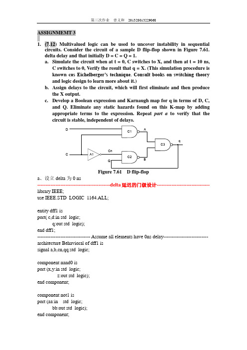
ASSIGNMEMT 31.(7.12) Multivalued logic can be used to uncover instability in sequentialcircuits. Consider the circuit of a sample D flip-flop shown in Figure 7.61.delta delay and that initially D = C = Q = 1.a.Simulate the circuit when at t = 0, C switches to X, and then at t = 10 ns,C switches to 0, Verify the result that q = X. (This simulation procedure isknown c as Eichelberger’s technique. Consult books on switching theory and logic design to learn more about it.)b.Assign delays to the circuit, which will first eliminate and then producethe X output.c.Develop a Boolean expression and Karnaugh map for q in terms of D, C,and Q. Eliminate any static hazards found on this K-map by adding appropriate terms to the expression. Repeat part a to verify that the circuit is stable, independent of delays.DCFigure 7.61 D flip-flopa、设立delta为0 ns--------------------------------------------delta延迟的门级设计-------------------------------- library IEEE;use IEEE.STD_LOGIC_1164.ALL;entity dff1 isport( c,d:in std_logic;q:out std_logic);end dff1;-------------------------------- Assume all elements have 0ns delay--------------------------- architecture Behavioral of dff1 issignal a,b,cn,qq:std_logic;component nand0 isport (x,y:in std_logic;z:out std_logic);end component;component not1 isport (aa:in std_logic;bb:out std_logic);end component;beginu0:nand0 port map(c,d,a);u1:not1 port map(c,cn);u2:nand0 port map(qq,cn,b);u3:nand0 port map(a,b,qq);q <= qq;end Behavioral;----------------------------------define nand0 and inv1----------------------------------------- library IEEE;use IEEE.STD_LOGIC_1164.ALL;entity nand0 isport (x,y:in std_logic;z:out std_logic);end entity;architecture rtl of nand0 isbeginz <= x nand y;end rtl;library IEEE;use IEEE.STD_LOGIC_1164.ALL;entity not1 isport(aa:in std_logic;bb:out std_logic);end entity;architecture behavior of not1 isbeginbb <= not aa;end behavior;1、在Design_Vision中可以看到设计原理图如下,和题目所给图示一样:2、在DVE中,利用testbench对其进行测试3、通过观察仿真波形可以看出,如下图所示,当C=1时,Q的状态和D输入的状态是始终同步的。
中科院_段成华_专用集成电路设计_作业 6
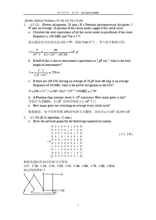
[Smith_ASICs]: Problem (15.15) (15.19) (15.20)1. (15.15) (Power dissipation, 20 min.) If a Pentium microprocessor dissipates 5W and, on average, 20 percent of the circuit nodes toggle every clock cyclea. Calculate the total capacitance of all the circuit nodes in picofarads if the clockfrequency is 100 MHz and V DD = 5 V .假定题意给出的是动态功耗5 W ,根据2=P CV f ∂,带入相关数据可得: 42285==100.22510P W C pf V f V HZ=∂⨯⨯ b. If half of this is due to interconnect capacitance at 2 pF ⋅cm –1, what is the total length of interconnect?–12/25 20pf cmC L cm =⨯= c. If there are 100 I/Os driving an average of 20 pF load off-chip at an averagefrequency of 50 MHz, what is the power dissipation in the I/Os?221100100*20*25*50MHZ 2.5P C V f pf V W =⨯==d. A Pentium chip contains about 3×10⁶ transistors. How many gates is this? 考虑作为CMOS ,3×106 晶体管构成1.5×10⁶个门e. How many gates are switching on average every clock cycle?根据题意,每个时钟周期20%的电路节点翻转,因此有650.2=1.510130⨯⨯⨯2. (15.19) (K –L algorithm, 15 min.)a. Draw the network graph for the following connectivity matrix:0000001000000001010000010001000010100010000100000001000000101000000010011000001000010011010000000010C ⎡⎤⎢⎥⎢⎥⎢⎥⎢⎥⎢⎥⎢⎥=⎢⎥⎢⎥⎢⎥⎢⎥⎢⎥⎢⎥⎢⎥⎢⎥⎣⎦ (15.26)根据连通矩阵相应的值可以得到17262834384549697989910C C C C C C C C C C C 、、、、、、、、、、画出网络图如下 1 2 3 4 56 7 8 9 10b. Draw the partitioned network graph for C with nodes 1–5 in partition A andnodes 6–10 in partition B. What is the cut weight? 1 2 3 4 56 7 8 9 10切割权重,=5ab a A b B W C ∈∈=∑c. Improve the initial partitioning using the K –L algorithm. Show the gains ateach stage. What problems did you find in following the algorithm and how do you resolve them?1、初始的增益0g =2、交换节点1−−→←−−6: g =1+0-0=1 2−−→←−−6: g =2+0-2=0 3−−→←−−6: g =0+0-0=0 1−−→←−−7: g =1+0-2=-1 2−−→←−−7: g =2+0-0=2 3−−→←−−7: g =0+0-0=0 1−−→←−−8: g =1+1-0=2 2−−→←−−8: g =2+1-2=1 3−−→←−−8: g =0+1-2=-1 1−−→←−−9: g =1-3-0=-2 2−−→←−−9: g =2-3-0=-1 3−−→←−−9: g =0-3-0=-3 1−−→←−−10: g =1-1-0=0 2−−→←−−10: g =2-1-0=1 3−−→←−−10: g =0-1-0=-14−−→←−−6: g =-1+0-0=-1 5−−→←−−6: g =-1+0-0=-1 4−−→←−−7: g =-1+0-0=-1 5−−→←−−7: g =-1+0-0=-1 4−−→←−−8: g =-1+1-0=0 5−−→←−−8: g =-1+1-0=0 4−−→←−−9: g =-1-3-2=-6 5−−→←−−9: g =-1-3-0=-4 4−−→←−−10: g =-1-1-0=-2 5−−→←−−10: g =-1-1-0=-2 得出:2−−→←−−7: g =2+0-0=2即为K-L 算法得出的最大增益。
超大规模集成电路第七次作业2016秋,段成华
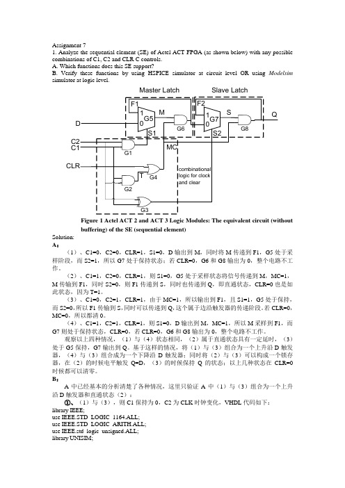
Assignment 71.Analyze the sequential element (SE) of Actel ACT FPGA (as shown below) with any possible combinations of C1, C2 and CLR C controls.A. Which functions does this SE support?B. Verify these functions by using HSPICE simulator at circuit level OR using Modelsim simulator at logic level.Master Latch Slave LatchFigure 1 Actel ACT 2 and ACT 3 Logic Modules: The equivalent circuit (withoutbuffering) of the SE (sequential element)Solution:A:(1)、C1=0,C2=0,CLR=1,S1=0,D输出到M,同时将M传递到F1,G5处于采样阶段,而S2=1,所以G7处于保持状态;若CLR=0,G6和G8输出为0,整个电路不工作。
(2)、C1=1,C2=0,CLR=1,则S1=0,G5处于采样状态将信号传递到M,MC=1,M传输到F1,同时S2=0,则F1传递到S,同时也传递到Q,即直通状态,CLR=0也是如此状态,因为T=1。
(3)、C1=0,C2=1,CLR=1,由于MC=1,所以输出到F1,且S1=1,G5处于保持,而S2=0,所以F1传输到S,同时可以传递到Q,这个属于边沿触发器的传递阶段。
若CLR=0,MC=0,所以都清0。
(4)、C1=1,C2=1,CLR=1,则S1=0,D输出到M,MC=1,所以M采样到F1,而G7则处于保持状态,CLR=0,若CLR=0,G6和G8输出为0,整个电路不工作。
- 1、下载文档前请自行甄别文档内容的完整性,平台不提供额外的编辑、内容补充、找答案等附加服务。
- 2、"仅部分预览"的文档,不可在线预览部分如存在完整性等问题,可反馈申请退款(可完整预览的文档不适用该条件!)。
- 3、如文档侵犯您的权益,请联系客服反馈,我们会尽快为您处理(人工客服工作时间:9:00-18:30)。
Configuration cfg_rs_ff of RS_FF is for struct for c0: nandgate use entity work.NANDGATE generic map(N=>2, tLH=>1 ns, tHL=>5 ns, STRN=>STRN_X01) port map(input(1)=>I_1, input(2)=>I_2, output=>output); end for; for c1: nandgate use entity work.NANDGATE generic map(N=>2, tLH=>2 ns, tHL=>4 ns, STRN=>STRN_X01) port map(input(1)=>I_1, input(2)=>I_2, output=>output); end for; end for; end cfg_rs_ff;
STRN: STRENGTH := STRN_X01);-strength port (INPUT: in STD_LOGIC;-- inputs OUTPUT: out STD_LOGIC); -- output end INVERTER; architecture A of INVERTER is signal CURRENTSTATE: STD_LOGIC := 'U'; subtype TWOBIT is STD_LOGIC_VECTOR (0 to 1); begin P: process variable NEXTSTATE: STD_LOGIC; variable DELTA: Time; variable NEXT_ASSIGN_VAL: STD_LOGIC; begin -- evaluate logical function -- if one input is '0' then the andgate output is '0' NEXTSTATE := not INPUT; NEXTSTATE := STRENGTH_MAP(NEXTSTATE, STRN); if (NEXTSTATE /= NEXT_ASSIGN_VAL) then -- compute delay case TWOBIT'(CURRENTSTATE & NEXTSTATE) is when "UU"|"UX"|"UZ"|"UW"|"U-"|"XU"|"XX"|"XZ"|"XW"| "X-"|"ZU"|"ZX"|"ZZ"|"ZW"|"Z-"|"WU"|"WX"|"WZ"| "WW"|"W-"|"-U"|"-X"|"-Z"|"-W"|"--"|"00"|"0L"| "LL"|"L0"|"11"|"1H"|"HH"|"H1" => DELTA := 0 ns; when "U1"|"UH"|"X1"|"XH"|"Z1"|"ZH"|"W1"|"WH"|"-1"| "-H"|"0U"|"0X"|"01"|"0Z"|"0W"|"0H"|"0-"|"LU"| "LX"|"L1"|"LZ"|"LW"|"LH"|"L-" => DELTA := tLH; when others => DELTA := tHL; end case; -- assign new value after internal delay CURRENTSTATE <= NEXTSTATE after DELTA; OUTPUT <= NEXTSTATE after DELTA; NEXT_ASSIGN_VAL := NEXTSTATE; end if; -- wait for signal changes wait on INPUT; end process P; end A;
Assignment 2
1. (7.10) Implement a NAND gate model using the IEEE nine-valued system. For the RS flip-flop shown in Figure 7.60, assume that both
—— ——
gate outputs are initially U, and that the two inputs R and S are initially 0 and switch to 1 simultaneously. Simulate the circuit at logic gate level when: a. Both gates have identical delays. b. The two gates have different delays. Compare your results.
(4) code for testbench
LIBRARY ieee; USE ieee.std_logic_1164.ALL; USE ieee.numeric_std.ALL; ENTITY TB_RD_FF IS END TB_RD_FF;
ARCHITECTURE behavior OF TB_RD_FF IS -- Component Declaration COMPONENT RS_FF PORT( R,S : IN std_logic; Y,NY : INOUT std_logic ); END COMPONENT; for TB_RD_FF: RS_FF use configuration work.cfg_rs_ff; signal R,S : std_logic :='0'; signal Y,NY : std_logic :='U'; -- Test Bench Statements BEGIN TB_RD_FF: RS_FF PORT MAP (R => R, S => S, Y => Y, NY => NY); stim_proc: process begin R <= transport '0'; S <= transport '0'; WAIT FOR 100 ns; R <= transport '1'; S <= transport '1'; WAIT FOR 100 ns; end process; END;
(5) test result
a、Both gates have identical delays.
b、The two gates have different delays. Compare your results.
在 cfg_rs_ff 中更改 generic map 中的延时参数 library IEEE; use IEEE.STD_LOGIC_1164.all; use IEEE.STD_LOGIC_MISC.all; 两与非门延时 不相同
(2) code for rs_ff
library IEEE; use IEEE.STD_LOGIC_1164.ALL; entity RS_FF is Port ( S : in STD_LOGIC; R : in STD_LOGIC; Y : inout STD_LOGIC; NY : inout STD_LOGIC); end RS_FF;
(3) code for configuration
library IEEE; use IEEE.STD_LOGIC_1164.all; use IEEE.STD_LOGIC_MISC.all; 两与非门延时 相同 Configuration cfg_rs_ff of RS_FF is for struct for c0: nandgate use entity work.NANDGATE generic map(N=>2, tLH=>1 ns, tHL=>5 ns, STRN=>STRN_X01) port map(input(1)=>I_1, input(2)=>I_2, output=>output); end for; for c1: nandgate use entity work.NANDGATE generic map(N=>2, tLH=>1 ns, tHL=>5 ns, STRN=>STRN_X01) port map(input(1)=>I_1, input(2)=>I_2, output=>output); end for; end for; end cfg_rs_ff;
S’ C1 YR’Fra bibliotekFigure 7.60
C2
Y’
R-S flip-flop
(1) code for nand_2
library IEEE; use IEEE.STD_LOGIC_1164.all; use IEEE.STD_LOGIC_MISC.all; entity NANDGATE is generic (N: Positive := 2;-- number of inputs tLH: Time := 10 ns; -- rise inertial delay tHL: Time := 15 ns; -- fall inertial delay STRN: STRENGTH := STRN_X01);-- output strength port (INPUT: in STD_LOGIC_VECTOR (1 to N);-- inputs OUTPUT: out STD_LOGIC); -- output end NANDGATE; architecture A of NANDGATE is signal CURRENTSTATE: STD_LOGIC := 'U'; subtype TWOBIT is STD_LOGIC_VECTOR (0 to 1); begin P: process variable NEXTSTATE: STD_LOGIC; variable DELTA: Time; variable NEXT_ASSIGN_VAL: STD_LOGIC; begin
