AOZ1020AI,AOZ1020AI,AOZ1020AI, 规格书,Datasheet 资料
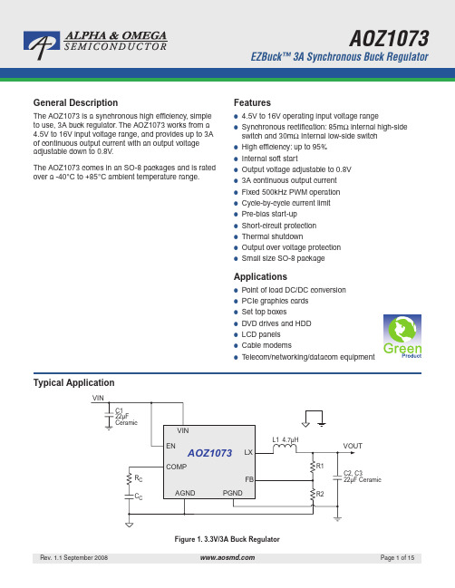
AOZ1016AI中文资料

Pin Function
Power ground. Electrically needs to be connected to AGND. Supply voltage input. When VIN rises above the UVLO threshold the device starts up. Reference connection for controller section. Also used as thermal connection for controller section. Electrically needs to be connected to PGND. The FB pin is used to determine the output voltage via a resistor divider between the output and GND. External loop compensation pin. The enable pin is active HIGH. Connect EN pin to VIN if not used. Do not leave the EN pin floating. PWM output connection to inductor. Thermal connection for output stage.
Applications
● ● ● ● ● ● ●
Point of load DC/DC conversion PCIe graphics cards Set top boxes DVD drives and HDD LCD panels Cable modems Telecom/networking/datacom equipment
海南话短句10句
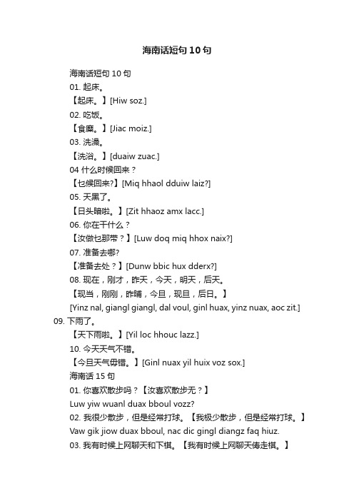
海南话短句10句海南话短句10句01. 起床。
【起床。
】[Hiw soz.]02. 吃饭。
【食糜。
】[Jiac moiz.]03. 洗澡。
【洗浴。
】[duaiw zuac.]04 什么时候回来?【乜候回来?】[Miq hhaol dduiw laiz?]05. 天黑了。
【日头暗啦。
】[Zit hhaoz amx lacc.]06. 你在干什么?【汝做乜那带?】[Luw doq miq hhox naix?]07. 准备去哪?【准备去处?】[Dunw bbic hux dderx?]08. 现在,刚才,昨天,今天,明天,后天。
【现当,刚刚,昨晡,今旦,现旦,后日。
】[Yinz nal, giangl giangl, dal voul, ginl huax, yinz nuax, aoc zit.] 09. 下雨了。
【天下雨啦。
】[Yil loc hhouc lazz.]10. 今天天气不错。
【今旦天气毋错。
】[Ginl nuax yil huix voz sox.]海南话15句01. 你喜欢散步吗?【汝喜欢散步无?】Luw yiw wuanl duax bboul vozz?02. 我很少散步,但是经常打球。
【我极少散步,但是经常打球。
】Vaw gik jiow duax bboul, nac dic gingl diangz faq hiuz.03. 我有时候上网聊天和下棋。
【我有时候上网聊天俦走棋。
】Vaw uc diz hhaol jioc mangc liaoz yil saox daow giz.04. 你吃饭了没有?【汝食糜过无?】Luw jiac moiz goqq vozz?05. 还没有吃,刚刚回来。
【仍无食噜,那那回来。
】Ziangw voz jiac lucc, naq naq dduiw laiz.06. 你教我做这道题好吗?【汝示我做这条题做得无?】Luw maix vaw doq jix ddiaoz dduaiz doq ddid vozz?07. 好极了!我可以帮你的忙。
JR劲锐佳芯片各型号使用明细
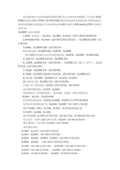
我司强势推出大电流电源IC\电源管理IC及大小功率的充电器IC,广泛应用在DVD, DVB(机顶盒),便携式DVD,车载DVD/VCD,液晶电视,液晶显示器,路由器,车载充电器,电瓶车控制电路板,车载冰箱,汽车音响,恒流串联LED灯驱动, VOIP,Audio,LCDM及各种小家电产品.XLSEMI产品应用领域1.DVB(机顶盒):XL1513,XL1580,XL1410(12V-1.8V/3.3V/5V/1A)2.Portable DVD:XL1410(12V-5V/3.3V/1.8V/1A),XL1580/XL1583(12 V-5V/1A)3.Video:XL1509-5.0S(12V-5V/1A)4.收音机电源:XL1509-ADJ,XL2576,XL2596组合DVD带音响/台式大收音机(带机芯):XL2576,XL2596,XL1509-ADJ5. LCD TV:XL1509-5.0/3.3、XL2596-5.0、6. LCDM:XL2596-5.0(12V-5V/3A),XL2596-3.3(15寸、17寸),XL15 07-5.0(12V-5V/1.5A)7. Audio:XL2596-5.0(12V-5V/3A)8. VOIP:XL1509-3.3(12V-3.3V/2A、12V-5V/1A),XL2596-3.39. 路由器:XL1509,XL1509-3.3,XL1410,XL151310. 液晶显示器:XL1501-3.3(12V-3.3V/3A)11.32寸以上液晶电视:XL4015(24V-12V/3A、24V-5V/5A)12.电梯控制板电源:XL2576,XL259613.锂电池包(多节锂电串联),移动电源,电池组,需恒压恒流充电:XL4001,XL4101,XL4015+358大功率锂电池包供电:XL6019,,XL6008,XL6007替代FP5138+MOS14.笔记本串联锂电池升压:XL6019,XL6008(12V~16V转19V/3A)15.车载MP3,MP4:XL1509,XL4001,XL1513(12V-5V/1 A)车载GPS:XL2596,XL150916.车载DVD:XL1507(12V-5V/1.5A,24V-5V/1.5A),XL1583(12V-5V/1.5A)17.公交车,出租车LED点阵显示屏:XL2576(24~36V转5V/1A)18.车载冰箱,汽车音响:XL4016(24V-12V/8A)19.车载充电器;XL1583,XL1410(12V~24V转5V/2A)XL4001,XL2001(12V~36V转5V/1.8A)XL4201,XL4101,XL2011,XL2012(12V~36V转5V/2.1A)XL4501,XL2013,(12V~36V转5V/3.1A~4.4A)XL1509(12V~36V转5V/1.5A),XL2576P(12V~36V转5V/1.5A),XL2576(12V~36V转5V/2A),XL2596(12V~36V转5V/2A),XL4013(12~24V转5V/3A),XL4015(12~24V转5V/4A),XL2001(12~24V转5V/1.8A),XL2011(12~24V转5V/2.1A),XL2012(12~24V转5V/2.4A),XL2013(12~24V转5V/3.2A),车充产品可以替代GL2576,GL2596,AX3007,AX3111,ACT4515,ACT4070,49 4+MOS,7500+MOS等方案20.上网本,笔记本车载充电器:60W以下的应用XL6009,XL6010,XL6011替代FP5138+MOS的方案,优点:线路简单,可靠性高升压方案(输入:10V~14V,输出:16V/19V,输出电流:2A,3A)升降压方案(输入:10V~30V,输出:12V/19V,输出电流:2A,3A)21.MR16射灯:XL30023*1W,4*1W ,5*1WLED模组驱动AC12V(DC10~16V)电子变压器升压供电:XL6003 5~7*1W,XL6005 10*1W车顶灯恒压输出,降压结构:XL1509车顶灯恒压输出,升压结构:XL6007,XL6008车顶灯恒压输出,升降压结构:XL6007,XL6008舞台灯XL2576,XL150922.电瓶车控制电路板:XL7001(60V转12V/5V/0.5A)23.安防产品:车载摄像头(小摄像头)供电:XL1509,XL1513小区,马路,建筑用的大摄像头,高速球供电:XL2596,XL1501摄像头里面用红外的LED灯驱动:XL1513,XL1530,XL1410市电和蓄电池混合供电:需要升降压应用XL6007,XL6008小区,大厦可视门铃对讲4寸,7寸屏供电:XL1509-ADJ,XL1410,XL1513,XL15 83(12V转5V/500mA)指示灯板:XL1513,XL141024.液晶电视数字屏,解码板电源驱动板:XL1513,XL153025.太阳能路灯,路标灯,庭院灯和5V~32V低压供电LED驱动,升降压应用领域:XL6003,XL6004,XL600526.大功率车载电源,降压,限流:XL4003+358,XL4005+358,XL4012+35827.降压型应用:XL4003,XL4005,XL4012可以替代PWM IC+MOS管等类似方案升压型应用:XL6007,XL6009,XL6010可以替代PWM IC+MOS管等类似方案升降压型应用:SEPIC BUCK-BOOST结构XL6007,XL6009,XL6010可以替代P WM IC+MOS管类似方案28.DVB:XL6007,XL6008马达天线供电(12V BOOST 19V/800mA)可以替代PWM IC+MOS管类似方案 CCD/CATVPMP/DSC/DSV/STB/VGA CardDPF(数码相框)PDALE D Panel背光LCD Panel背光移动电源应急充电器,可以替代FP5210+MOS,FP6210升压应用领域29.升压,恒压LED模组驱动:XL6007,XL6008,可以替代FP5210+MOS,FP621 0升压应用领域30.17寸以下LED背光驱动:XL6007,可以替代AMC3202的应用领域[1]XL14102APWM降压DC/DC,SOP8,输入3.6-18V,输出1.22V-16V转换效率高达90%,可替代BM1410A,TD1410,AP1512,AP1513,RM1410,GT1510,EC94 10,EC9410C,SD46520,ACT4060功能兼容AOZ1010AI,AOZ1015AI,EC9406[2]XL15833APWM降压DC/DC,SOP8,输入3.6-20V,输出1.23V-18V转换效率高达90%,可替代MP2355,ACT4060,MP1583,ZA3020,AOZ1014,MP1593[3]XL15132APWM降压DC/DC,SOP8,输入3.6-18V,输出0.8V-16V转换效率高达90%,可替代AP1513,OCP2020,BM1513/A,AX3101,RM2060,CX1513,EC9 413,AP1510,AP1520,AP1533,AP1534,AP5002功能兼容AOZ1010AI,AOZ1015AI,EC9406[4]XL15303APWM降压DC/DC,SOP8,输入3.6-18V,输出0.8V-16V转换效率高达90%,可替代AP1530,AP1538,AP1539,[5]XL25763APWM降压DC/DC,TO263/TO220,输入电压范围3.6-45V,可完全替换AE2576,BM2576,TD2576,AP1512/A,LM2576,LM2576,MIK2575,MIK2576A MC2576,OCP2006,HWD2575,EC942576[6]XL25963APWM降压DC/DC,TO263/TO220,输入电压范围3.6-45V,可完全替换AE2596,BM2596,TD2596,AP1501/A,AP1506,LM2596,AMC2596,MIK2596,OCP2011,OCP2016,GT1500,GT1504,AX2596,EC9401,CM2596S[7]XL15092APWM降压DC/DC,SOP8,输入3.6-36V,转换效率高达90%,功能替换LM2594,AE1509,TD1509,AP1509,OCP2019,HWD61410,EC9409,CM25 93.[8]XL4001,XL4101,XL4201,XL4501车载充电器,点烟器,恒流LED驱动,专用芯片150K2A/3A外部可调限流PWM降压DC/DC输入4.6V-40V可替代2576+431+324方案,34063+MOS+431+324方案[9]XL15073APWM降压DC/DC,TO252,输入3.6-36V,转换效率高达85%可完全替换AE1507,TD1507,AP1507,OCP2017,EC9407[10]XL4015大电流5APWM降压DC/DC,输入8-36V,输出0.8V-33V转换效率高达95%(功能兼容)---AOZ1014,LM2677,LM2678,LM2679[11]XL4012大电流12APWM降压DC/DC,TO220输入8-40V,输出0.8V-33V转换效率高达95%(功能兼容)---LM2677,LM2678,LM2679。
北师大版小学二年级语文生字词,注过拼音

g ni rtj g h ingc e二年级上册d i y i d a nyu an 第一单元 qi u ti a nd ao 1秋天到h o ngqi u qi u sh ou 中秋、秋收、秋风、春秋q u ch a ngg e g e sh e 曲、唱歌、歌声、ji u ji u yu g i u b a ji u ti aji n u sh $h u ji u 九:九月、九百、九天、九十、数九、 sh ou hu i sh ois h o ud ao sh o ushi 收:回收、收到、收拾、 mang b a ng a ng li rfi mang 忙:帮忙、连忙 l ng l nghu a h aiia g b o l a g 浪:浪花、海浪、波浪zhu an zhu a t n <u xu d nzhu an zhu a d eng zhu (&qu an 转:转头、旋转、转动、转圈、hu o h o ngdef e ngy e 2火红的枫叶x tn sh i z o ng ch a xi a ti e sh i h e 寻总、朝、霞、贴、诗」 r a z i a r a er t u r anr O h cu然:自然、然而、突然、然后、e r e rqi e e rsh i而:而且、而是、b i b ir u du i b i b i ji a p i ngb ib i p in 比:比如、对比、比较、评比、比拼、zhu an li 转、shu a 、爽 ng f an h a shu a ng ji 、翻、寒、霜、 j u y a 、菊、雁 izh o i u ti a qi 天、秋ID“予最丿凰丿凰丿曝「m 如一它=>o q v -c s u >o _ I -C SN illsoB xM 吕 < 叩吕,w 吕,吕w二戸B 0 Ql|B_>o 4B_D au心6 B二<<f^/ 區<〔<UQ£Q40BduQquQq心sq 一Qp ni|Q 一q6⑥ ipc一q q 一q,*栏,M w,w歿-B9ni|z二qnil 。
创维E710U资料【范本模板】

创维E710U(9R15机芯)系列维护与维修一、功能调试与升级本系列机芯产品型号见表1所示,主板见图1所示。
表11、网络设置使用遥控器进行网络设置:按遥控器上的“天赐”→“设置”→“网络设置”→进行“有线/无线"选择。
2、工厂模式的进入与退出方法方法一:在“本机信息”下,用遥控器按“上上下下左右左右”,即可进入工厂菜单。
方法二:首先将音量减到“00”,然后按住键控板上的“音量减”键,同时按一下遥控器上的“返回”键,即可进入工厂模式。
方法三:当工厂模式菜单里的“单键模式开关”为“开”时,按工厂遥控器上的“工厂调试”键(3FH),即可进入工厂模式。
按“返回"键或“工厂调试”键(3FH)或“屏显”键,均可退出工厂模式。
3、软件升级9R15机芯有主程序和UBOOT程序两部分程序可进行升级。
9R15机芯的主要数据(如MAC地址、HDMI KEY、防串货码)均放置在EEPROM(其主要地址说明:串码识别地址05H ,串码起始地址07H ,HDCPKEY起始地址27H,MAC地址170H)中,在生产预调时需写入,EEPROM初始化等操作均不会被改写,在修理时请尽量不要更换EEPROM,否则,会影响正常使用。
本机芯有两个位号的芯片需在贴片前烧录,分别如下:U9(主板位号):烧录内容是BOOT程序和主程序(两者二合一的镜像文件),文件类型是*.img(具体文件名请参考“设计技术资料电子文档归档清单一览表”,该软件由设计师制作,在研发总部技术管理部归档).请注意该芯片的内容必须正确,否则,主程序将无法正常启动,也无法在线升级主程序.U23(主板位号):烧录内容是EEPROM母片,文件类型是*.bin(具体文件名请参考“设计技术资料电子文档归档清单一览表",该软件由设计师制作,在技术管理部归档)。
如果该芯片未经烧录,那么系统启动时会自动对EEPROM进行初始化,但初始化的内容和母片数据不完全相同(如频点等),且工厂模式中EEPROM 版本将显示“INIT IS OK"。
小学拼音--数学家阿基米德故事1汇总

sh Cxu 可 a ch <!ni ingr fndeg Csh i zhu mg sh u数学家陈景润的故事--撞 树ch ! ingr Unsh iw d gu dzh O mingdesh U xu eii a c digxiGOt a Uebiex i hu a nsh U xu e zh iy do陈景润是我国著名的数学家,从小,他就特别喜欢数学。
只如ch <!nj inz d d d sh u j ih !eji 连 igu och engzha ng t q i U n !ggOuwongqu esu dudesh i ing沉浸在代数、几何的解题过程中,他就能够忘却所有的事情。
y ig e h u ch mdezh a ngw u zu ih duy j i來 edexick e ^gxi angle xu eshm gmery a ngjidezduch u一个初春的中午,最后一节课的下课铃响了,学生们拥挤的走出ji C osh i hu f i a ch if cn ch <!nj ingr U nb O inb U mcn z d z d zu ihdu t a dngsh U b a li n dch u y ib Si教室,回家吃饭。
陈景润不紧不慢,走在最后。
他从书包里拿出一本g a ge dngl aosh in cji e d desh U xu esh u bi a nz d ubi a k d刚从老师那借来的数学书,边走边看。
t a zh ig U zhu a x i zh izh idek cnsh u ji G m d m d depi a nl ile f angxi eng t abOzh ibiji d他只顾专心致志的看书,脚慢慢的箱离了 方 向,他不知不觉ch cozh col Cbi a dexi aosh U z d q U zh f i g a i y a u y ish e ng ch !ij ingr U nzhu a ngd d ole y ik esh U t ak d朝着路边的小树走去。
AOZ1031AI
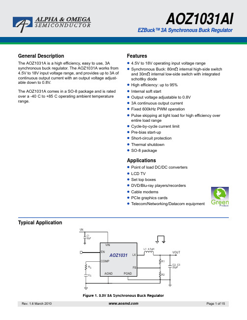
Features
z 4.5V to 18V operating input voltage range z Synchronous Buck: 80mΩ internal high-side switch
20V -0.7V to VIN+0.3V -3V for 20 nS -0.3V to VIN+0.3V -0.3V to 6V -0.3V to 6V -0.3V to +0.3V +150°C -65°C to +150°C 2.0kV
Note: 1. Devices are inherently ESD sensitive, handling precautions are
Symbol
Parameter
Conditions
Min.
VIN VUVLO
IIN IOFF VFB
IFB VEN
Supply Voltage Input under-voltage lockout threshold Supply current (Quiescent) Shutdown supply current Feedback Voltage Load regulation Line regulation Feedback voltage input current EN input threshold
VIN = 12V VIN = 5V VIN = 12V VIN = 5V
Notes: 3. The device is not guaranteed to operate beyond the Maximum Operating ratings.
HSG1020说明书[1]
![HSG1020说明书[1]](https://img.taocdn.com/s3/m/a50cf627482fb4daa58d4b5f.png)
指标参数 -10~+55 =(92 +3-2)% DC19~DC28 DC22~DC26
=65(DC24V) =30 =2.5
80~110 电源防反接 130(不含编码模块) 130×90×34(h) 68×40×17(h) 依据 B型警报器编码模块带载能力确定
单位 ℃ RH V V mA m S dB
4.4 在接线、安装完毕后,将底板下部边沿上的突出卡条嵌入上盖下部的卡槽内,并将上盖上 部的卡槽对正底板上部的的弹性止退勾(见图 4)适度用力按压上盖直到听到底板止退勾 嵌入上盖卡槽时的咬合声。
四、注意事项
本产品安装时,建议使用墙内预埋接线盒配套安装,如必须进行明线接线,则用户需自备固定用 螺丝钉,本产品自带 M4×20 的标准螺丝钉,明装线缆可通过警报器上下进线敲落孔接入警报器。
-6-
力。 保修与服务 保修说明:
消防电话总机在正常使用情况下,免费保修期为 1 年,并负责产品终身维修。由于用户 自行拆卸主机造成的损害,不在保修范围之列。
保修地点:北京
联系我们:
销售部
地址:北京市朝阳区金盏乡雷庄村东高路 电话:(010)64792099 64792100 传真:(010)64391040 邮编:100018
-5-
HOVER
5、 本产品发声部分工作时,声音非常尖利,在调试状态下发声应注意不要惊吓他人,特别是 儿童、老人、孕妇、精神病患者等。
6、 如想利用该产品发挥其它作用或有特殊要求,希望用户与本公司联系,我们愿意为您进行 改装服务。
7、 如因产品质量问题导致用户不能正常使用该产品,请速与本公司联系,我们将尽快为您解 决使用中遇到的各类问题。
将本产品无极性的接入火灾探测报警系统的总线中。
AOZ1021AI中文资料
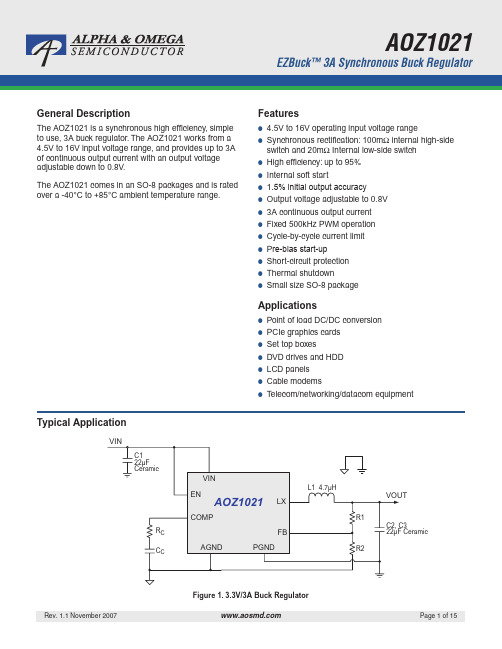
Applications
● ● ● ● ● ● ●
Point of load DC/DC conversion PCIe graphics cards Set top boxes DVD drives and HDD LCD panels Cable modems Telecom/networking/datacom equipment
Rev. 1.1 November 2007
Page 2 of 15
元器件交易网
ADVANCED INFORMATION
AOZ1021
Block Diagram
VIN
EN
UVLO & POR
5V LDO Regulator
Internal +5V
200 0.6
nA
V mV
MODULATOR 600 6 kHz % % V/V µA / V 5.0 A °C 6.5 130 200 23 36 ms
PROTECTION
tSS
Soft Start Interval High-Side Switch On-Resistance
PWM OUTPUT STAGE mΩ mΩ
Note: 3. Specifications in BOLD indicate an ambient temperature range of -40°C to +85°C. These specifications are guaranteed by design.
Rev. 1.1 November 2007
Page 1 of 15
元器件交易网
AOZ1021
Ordering Information
AOZ1022PI, 规格书,Datasheet 资料
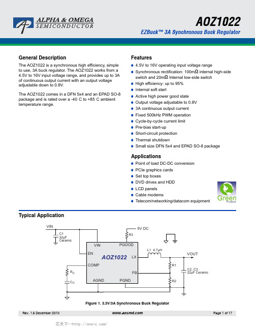
General DescriptionThe AOZ1022 is a synchronous high efficiency, simple to use, 3A buck regulator. The AOZ1022 works from a 4.5V to 16V input voltage range, and provides up to 3A of continuous output current with an output voltage adjustable down to 0.8V.The AOZ1022 comes in a DFN 5x4 and an EPAD SO-8 package and is rated over a -40°C to +85°C ambient temperature range.Features●4.5V to 16V operating input voltage range●Synchronous rectification: 100mΩ internal high-side switch and 20mΩ Internal low-side switch●High efficiency: up to 95%●Internal soft start●Active high power good state●Output voltage adjustable to 0.8V●3A continuous output current●Fixed 500kHz PWM operation●Cycle-by-cycle current limit●Pre-bias start-up●Short-circuit protection●Thermal shutdown●Small size DFN 5x4 and EPAD SO-8 package Applications●Point of load DC-DC conversion●PCIe graphics cards●Set top boxes●DVD drives and HDD●LCD panels●Cable modems●Telecom/networking/datacom equipmentFigure 1. 3.3V/3A Synchronous Buck RegulatorOrdering InformationAOS Green Products use reduced levels of Halogens, and are also RoHS compliant. Please visit /web/quality/rohs_compliant.jsp for additional information.Pin ConfigurationPin DescriptionPart NumberAmbient Temperature RangePackageEnvironmentalAOZ1022DI -40°C to +85°C DFN 5x4AOZ1022-40°C to +85°CEPAD S0-8GreenPin Number Pin NamePin Function5x4 DFN-8Exposed Pad SO-811PGND Power ground. PGND needs to be electrically connected to AGND.22V IN Supply voltage input. When V IN rises above the UVLO threshold and EN is logic high, the device starts up.33AGND Analog ground. AGND is the reference point for controller section. AGND needs to be electrically connected to PGND.44FB Feedback input. The FB pin is used to set the output voltage via a resistor divider between the output and AGND.55COMP External loop compensation pin. Connect a RC network between COMP and AGND to compensate the control loop.66EN Enable pin. Pull EN to logic high to enable the device. Pull EN to logic low to disable the device. if on/off control is not needed, connect it to V IN and do not leave it open. 7Pad LX Switching node. LX is the drain of the internal PFET. LX is used as the thermal pad of the power stage.87PGOODPower Good Output. PGOOD is an open-drain output that indicates the status of out-put voltage. PGOOD is pulled low when output is below 90% of the normal regula-tion.8NCNo Connect. Pin 8 is not internally connected.Block DiagramAbsolute Maximum RatingsExceeding the Absolute Maximum Ratings may damage the device.Note:1. Devices are inherently ESD sensitive, handling precautions are required. Human body model rating: 1.5k Ω in series with 100pF.Recommended Operating ConditionsThe device is not guaranteed to operate beyond the Maximum Recommended Operating Conditions.Note:2. The value of ΘJA is measured with the device mounted on1-in 2 FR-4 board with 2oz. Copper, in a still air environment with T A = 25°C. The value in any given application depends on the user's specific board design.ParameterRatingSupply Voltage (V IN )18VLX to AGND -0.7V to V IN +0.3V EN to AGND -0.3V to V IN +0.3VFB to AGND -0.3V to 6V COMP to AGND -0.3V to 6V PGND to AGND -0.3V to 0.3V PGOOD to AGND -0.3V to 6VJunction Temperature (T J )+150°CStorage Temperature (T S )-65°C to +150°CESD Rating (1)2.0kVParameterRatingSupply Voltage (V IN ) 4.5V to 18V Output Voltage Range 0.8V to V IN Ambient Temperature (T A )-40°C to +85°CPackage Thermal Resistance Exposed Pad SO-8 (ΘJA )(2)50°C/WElectrical CharacteristicsT A = 25°C, V IN = V EN = 12V, V OUT = 3.3V unless otherwise specified.(3)Note:3. Specifications in BOLD indicate an ambient temperature range of -40°C to +85°C. These specifications are guaranteed by design.SymbolParameterConditions Min.Typ.Max.UnitsV IN Supply Voltage4.516V V UVLO Input Under-Voltage Lockout Threshold V IN Rising V IN Falling4.13.7VI IN Supply Current (Quiescent)I OUT = 0, V FB = 1.2V, V EN > 1.2V 1.6 2.5mA I OFF Shutdown Supply Current V EN = 0V 320µA V FBFeedback Voltage T A = 25°C0.7880.80.812V Load Regulation 0.5%Line Regulation1%I FB Feedback Voltage Input Current 200nAENABLEV EN EN Input Threshold Off Threshold On Threshold20.6V V HYS EN Input Hysteresis 100mVMODULATORf O Frequency350500600kHz D MAX Maximum Duty Cycle 100%D MIN Minimum Duty Cycle 6%G VEA Error Amplifier Voltage Gain 500V / V G EA Error Amplifier Transconductance 200µA / VPROTECTIONI LIMCurrent Limit4.05.0A Over-Temperature Shutdown LimitT J Rising T J Falling150100°Ct SS Soft Start Interval 357ms POWER GOODV OLPG PGOOD LOW Voltage I OL = 1mA0.5V PGOOD Leakage1µA V PGL PGOOD Threshold Voltage879092%V O PGOOD Threshold Voltage Hysteresis 3%t PGPGOOD Delay Time128µsPWM OUTPUT STAGEHigh-Side Switch On-ResistanceV IN = 12V V IN = 5V97166130200m ΩLow-Side Switch On-ResistanceV IN = 12V V IN = 5V18302336m ΩLight Load OperationFull Load (CCM) OperationStartup to Full LoadShort Circuit Protection50% to 100% Load TransientShort Circuit Recovery1s/di v 1s/di v100s/di vV 0.1V 20m V 2V 10lin 1A/di V 100m lo1A/di IL 1A/di V 10LX10V 2IL 2A/diTypical Performance CharacteristicsCircuit of Figure 1. T A = 25°C, V IN = V EN = 12V, V OUT = 3.3V unless otherwise specified.EfficiencyThermal Derating CurvesDetailed DescriptionThe AOZ1022 is a current-mode step down regulator with integrated high-side PMOS switch and a low-side NMOS switch. It operates from a 4.5V to 16V input voltage range and supplies up to 3A of load current. The duty cycle can be adjusted from 6% to 100% allowing a wide range of output voltage. Features include enable control, Power-On Reset, input under voltage lockout, output over voltage protection, active high power good state, fixed internal soft-start and thermal shut down.Enable and Soft StartThe AOZ1022 has an internal soft start feature to limitin-rush current and ensure the output voltage ramps up smoothly to regulation voltage. A soft start process begins when the input voltage rises to 4.1V and voltage on EN pin is HIGH. In the soft start process, the output voltage is typically ramped to regulation voltage in 4ms. The 4ms soft start time is set internally.The EN pin of the AOZ1022 is active HIGH. Connect the EN pin to V IN if the enable function is not used.Pulling EN to ground will disable the AOZ1022. Do not leave it open. The voltage on the EN pin must be above 2V to enable the AOZ1022. When voltage on the ENpin falls below 0.6V, the AOZ1022 is disabled. If an appli-cation circuit requires the AOZ1022 to be disabled, an open drain or open collector circuit should be used to interface to the EN pin.Power GoodThe output of Power-Good is an open drain N-channel MOSFET which supplies an active high power good stage. A pull-up resistor (R3) should connect this pin to a DC power trail with maximum voltage of 6V. TheAOZ1022 monitors the FB voltage. When FB voltage is lower than 90% of the normal voltage, N-channel MOSFET turns on and the Power-Good pin is pulled low. This indicates the power is abnormal.Steady-State OperationUnder steady-state conditions, the converter operates in fixed frequency and Continuous-Conduction Mode (CCM).The AOZ1022 integrates an internal P-MOSFET as the high-side switch. Inductor current is sensed by amplifying the voltage drop across the drain to source of the high side power MOSFET. Output voltage is divided down by the external voltage divider at the FB pin. The difference of the FB pin voltage and reference is amplified by the internal transconductance error amplifier. The error voltage, which shows on the COMP pin, is compared against the current signal, which is sum of inductor current signal and ramp compensation signal, at the PWM comparator input. If the current signal is less than the error voltage, the internal high-side switch is on. The inductor current flows from the input through the inductor to the output. When the current signal exceeds the error voltage, the high-side switch is off. The inductor current is freewheeling through the internal low-side N-MOSFET switch to output. The internal adaptive FET driver guarantees no turn on overlap of both high-side andlow-side switch.Comparing with regulators using freewheeling Schottky diodes, the AOZ1022 uses freewheeling NMOSFET to realize synchronous rectification. It greatly improves the converter efficiency and reduces power loss in thelow-side switch.The AOZ1022 uses a P-Channel MOSFET as the high-side switch. It saves the bootstrap capacitor normally seen in a circuit which is using an NMOS switch. It allows 100% turn-on of the high-side switch to achieve linear regulation mode of operation. The minimum voltage drop from V IN to V O is the load current x DC resistance of MOSFET + DC resistance of buck inductor. It can be calculated by the equation below:where;V O_MAX is the maximum output voltage,V IN is the input voltage from 4.5V to 16V,I O is the output current from 0A to 3A, andR DS(ON) is the on resistance of internal MOSFET, the value is between 97mΩ and 200mΩ depending on input voltage and junction temperature.Switching FrequencyThe AOZ1022 switching frequency is fixed and set by an internal oscillator. The practical switching frequency could range from 350kHz to 600kHz due to device variation.Output Voltage ProgrammingOutput voltage can be set by feeding back the output to the FB pin by using a resistor divider network. See the application circuit shown in Figure 1. The resistor divider network includes R1 and R2. Usually, a design is started by picking a fixed R2 value and calculating the required R1 with equation on the next page:V O_MAX V IN I O R DS ON()×–=V O0.81R1R2------+⎝⎠⎜⎟⎛⎞×=Some standard value of R 1, R 2 and most used output voltage values are listed in Table 1.The combination of R 1 and R 2 should be large enough to avoid drawing excessive current from the output, which will cause power loss.Since the switch duty cycle can be as high as 100%, the maximum output voltage can be set as high as the input voltage minus the voltage drop on upper PMOS and inductor.Protection FeaturesThe AOZ1022 has multiple protection features to prevent system circuit damage under abnormal conditions. Over Current Protection (OCP)The sensed inductor current signal is also used for over current protection. Since the AOZ1022 employs peak current mode control, the COMP pin voltage is proportional to the peak inductor current. The COMP pin voltage is limited to be between 0.4V and 2.5V internally. The peak inductor current is automatically limited cycle by cycle.When the output is shorted to ground under faultconditions, the inductor current decays very slow during a switching cycle because of V O = 0V. To prevent cata-strophic failure, a secondary current limit is designed inside the AOZ1022. The measured inductor current is compared against a preset voltage which represents the current limit, between 3.5A and 5.0A. When the output current is more than current limit, the high side switch will be turned off. The converter will initiate a soft start once the over-current condition is resolved.Power-On Reset (POR)A power-on reset circuit monitors the input voltage. When the input voltage exceeds 4.1V, the converter starts operation. When input voltage falls below 3.7V, the converter shuts down.Thermal ProtectionAn internal temperature sensor monitors the junction temperature. It shuts down the internal control circuit and high side PMOS if the junction temperature exceeds 150°C. The regulator will restart automatically under the control of soft-start circuit when the junction temperature decreases to 100°C.Application InformationThe basic AOZ1022 application circuit is show in Figure 1. Component selection is explained below.Input CapacitorThe input capacitor must be connected to the V IN pin and PGND pin of AOZ1022 to maintain steady input voltage and filter out the pulsing input current. The voltage rating of input capacitor must be greater than maximum input voltage plus ripple voltage.The input ripple voltage can be approximated by equa-tion below:Since the input current is discontinuous in a buckconverter, the current stress on the input capacitor is another concern when selecting the capacitor. For a buck circuit, the RMS value of input capacitor current can be calculated by:if we let m equal the conversion ratio:The relation between the input capacitor RMS current and voltage conversion ratio is calculated and shown in Figure 2 on the next page. It can be seen that when V O is half of V IN , C IN is under the worst current stress. The worst current stress on C IN is 0.5 x I O .For reliable operation and best performance, the input capacitors must have current rating higher than I CIN_RMS at worst operating conditions. Ceramic capacitors are preferred for input capacitors because of their low ESR and high current rating. Depending on the application circuits, other low ESR tantalum capacitor may also be used. When selecting ceramic capacitors, X5R or X7R type dielectric ceramic capacitors should be used for their better temperature and voltage characteristics.V O (V)R 1 (k Ω)R 2 (k Ω)0.8 1.0open 1.2 4.99101.51011.51.812.710.22.521.5103.331.1105.052.310ΔV IN I O f C IN ×-----------------1V O V IN --------–⎝⎠⎜⎟⎛⎞V O V IN--------××=I CIN_RMS I O V O V IN --------1V O V IN --------–⎝⎠⎜⎟⎛⎞×=VO V IN--------m =Figure 2. I CIN vs. Voltage Conversion RatioNote that the ripple current rating from capacitor manu-factures are based on certain amount of life time. Further de-rating may be necessary in practical design. InductorThe inductor is used to supply constant current to output when it is driven by a switching voltage. For given input and output voltage, inductance and switching frequency together decide the inductor ripple current, which is:The peak inductor current is:High inductance gives low inductor ripple current but requires larger size inductor to avoid saturation. Low ripple current reduces inductor core losses. It also reduces RMS current through inductor and switches, which results in less conduction loss. Usually, peak to peak ripple current on inductor is designed to be 20%to 30% of output current.When selecting the inductor, make sure it is able to handle the peak current without saturation even at the highest operating temperature.The inductor takes the highest current in a buck circuit. The conduction loss on inductor need to be checked for thermal and efficiency requirements.Surface mount inductors in different shape and styles are available from Coilcraft, Elytone and Murata. Shielded inductors are small and radiate less EMI noise. But they cost more than unshielded inductors. The choice depends on EMI requirement, price and size.Output CapacitorThe output capacitor is selected based on the DC output voltage rating, output ripple voltage specification and ripple current rating.The selected output capacitor must have a higher rated voltage specification than the maximum desired output voltage including ripple. De-rating needs to be consid-ered for long term reliability.Output ripple voltage specification is another important factor for selecting the output capacitor. In a buck con-verter circuit, output ripple voltage is determined by inductor value, switching frequency, output capacitor value and ESR. It can be calculated by the equation below:where,C O is output capacitor value, andESR CO is the equivalent series resistance of the output capacitor.When low ESR ceramic capacitor is used as output capacitor, the impedance of the capacitor at the switching frequency dominates. Output ripple is mainly caused by capacitor value and inductor ripple current. The output ripple voltage calculation can be simplified to:If the impedance of ESR at switching frequency dominates, the output ripple voltage is mainly decided by capacitor ESR and inductor ripple current. The output ripple voltage calculation can be further simplified to:For lower output ripple voltage across the entire operat-ing temperature range, X5R or X7R dielectric type of ceramic, or other low ESR tantalum are recommended to be used as output capacitors.In a buck converter, output capacitor current is continuous. The RMS current of output capacitor is decided by the peak to peak inductor ripple current. It can be calculated by:Usually, the ripple current rating of the output capacitor is a smaller issue because of the low current stress. When the buck inductor is selected to be very small and induc-ΔI LV Of L×----------1V OV IN--------–⎝⎠⎜⎟⎛⎞×=I Lpeak I OΔI L2 --------+=ΔV OΔI L ESR CO18f C O××-------------------------+⎝⎠⎛⎞×=ΔV OΔI L18f C O××-------------------------⎝⎠⎛⎞×=ΔV OΔI L ESR CO×=I CO_RMSΔI L12----------=tor ripple current is high, the output capacitor could be overstressed.Loop CompensationThe AOZ1022 employs peak current mode control for easy use and fast transient response. Peak current mode control eliminates the double pole effect of the output L&C filter. It greatly simplifies the compensation loop design.With peak current mode control, the buck power stage can be simplified to be a one-pole and one-zero system in frequency domain. The pole is the dominant pole can be calculated by:The zero is an ESR zero due to output capacitor and its ESR. It is can be calculated by:where;C O is the output filter capacitor,R L is load resistor value, andESR CO is the equivalent series resistance of output capacitor.The compensation design is actually to shape theconverter control loop transfer function to get the desired gain and phase. Several different types of compensation network can be used for the AOZ1022. In most cases, a series capacitor and resistor network connected to the COMP pin sets the pole-zero and is adequate for a stable high-bandwidth control loop.In the AOZ1022, FB pin and COMP pin are the inverting input and the output of internal error amplifier. A series R and C compensation network connected to COMP provides one pole and one zero. The pole is:where;G EA is the error amplifier transconductance, which is 200 x 10-6 A/V,G VEA is the error amplifier voltage; and C 2 is compensation capacitor in Figure 1.The zero given by the external compensation network, capacitor C 2 and resistor R 3, is located at:To design the compensation circuit, a target crossover frequency f C for close loop must be selected. The system crossover frequency is where control loop has unity gain. The crossover is the also called the converter bandwidth. Generally a higher bandwidth means faster response to load transient. However, the bandwidth should not be too high because of system stability concern. When design-ing the compensation loop, converter stability under all line and load condition must be considered.Usually, it is recommended to set the bandwidth to be equal or less than 1/10 of switching frequency. The AOZ1022 operates at a frequency range from 350kHz to 600kHz. It is recommended to choose a crossover frequency equal or less than 40kHz.The strategy for choosing R C and C C is to set thecross over frequency with R C and set the compensator zero with C C . Using selected crossover frequency, f C , to calculate R 3:where;where f C is desired crossover frequency. For best performance, f C is set to be about 1/10 of switching frequency,V FB is 0.8V,G EA is the error amplifier transconductance, which is 200 x 10-6 A/V, andG CS is the current sense circuit transconductance, which is 6.86 A/VThe compensation capacitor C C and resistor R C together make a zero. This zero is put somewhere close to the dominate pole f p1 but lower than 1/5 of selected crossover frequency. C 2 can is selected by:The above equation can be simplified to:f p 112πC O R L××----------------------------------=f Z 112πC O ESR CO××------------------------------------------------=f p 2G EA2πC C G VEA××------------------------------------------=f Z 212πC C R C××-----------------------------------=f C 40kHz=R C f C V O V FB ----------2πC 2×G EA G CS×-----------------------------××=C C 1.52πR C f p 1××----------------------------------=C C C O R L×R C---------------------=An easy-to-use application software which helps to design and simulate the compensation loop can be found at .Thermal Management and Layout ConsiderationIn the AOZ1022 buck regulator circuit, high pulsing current flows through two circuit loops. The first loop starts from the input capacitors, to the V IN pin, to the LX pins, to the filter inductor, to the output capacitor and load, and then return to the input capacitor through ground. Current flows in the first loop when the high side switch is on. The second loop starts from inductor, to the output capacitors and load, to the anode of Schottky diode, to the cathode of Schottky diode. Current flows in the second loop when the low side diode is on.In PCB layout, minimizing the two loops area reduces the noise of this circuit and improves efficiency. A ground plane is strongly recommended to connect input capaci-tor, output capacitor, and PGND pin of the AOZ1022.In the AOZ1022 buck regulator circuit, the major power dissipating components are the AOZ1022 and the output inductor. The total power dissipation of converter circuit can be measured by input power minus output power.The power dissipation of inductor can be approximately calculated by output current and DCR of inductor.The actual junction temperature can be calculated with power dissipation in the AOZ1022 and thermal impedance from junction to ambient.The maximum junction temperature of AOZ1022 is 150°C, which limits the maximum load current capability. Please see the thermal de-rating curves for maximum load current of the AOZ1022 under different ambient temperature.The thermal performance of the AOZ1022 is strongly affected by the PCB layout. Extra care should be taken by users during design process to ensure that the ICwill operate under the recommended environmental conditions.The AOZ1022 comes in an EPAD SO-8 package. Layout tips are listed below for the best electric and thermal performance. Figure 3 illustrates a PCB layout example of the AOZ1022.1.The LX pins are connected to internal PFET andNFET drains. They are low resistance thermalconduction path and the most noisy switching node.Connected a large copper plane to the LX pin to help thermal dissipation.2.Do not use thermal relief connection to the V IN andthe PGND pin. Pour a maximized copper area to the PGND pin and the V IN pin to help thermal dissipation.3.Input capacitor should be connected to the V IN pinand the PGND pin as close as possible.4. A ground plane is preferred. If a ground plane isnot used, separate PGND from AGND and connect them only at one point to avoid the PGND pin noise coupling to the AGND pin.5.Make the current trace from LX pins to L to Co to thePGND as short as possible.6.Pour copper plane on all unused board area andconnect it to stable DC nodes, like V IN, GND or V OUT.7.Keep sensitive signal trace far away form the LXpins.P total_loss V IN I IN V O I O×–×=P inductor_loss I O2R inductor 1.1××=T junction P total_loss P inductor_loss–()Θ×JA =Package Dimensions, EPAD SO-8Tape and Reel Dimensions, EPAD SO-8Part MarkingAs used herein:1. Life support devices or systems are devices or systems which, (a) are intended for surgical implant into the body or (b) support or sustain life, and (c) whose failure to perform when properly used in accordance with instructions for use provided in the labeling, can be reasonably expected to result in a significant injury of the user.2. A critical component in any component of a life support, device, or system whose failure to perform can be reasonably expected to cause the failure of the life support device or system, or to affect its safety or effectiveness.This data sheet contains preliminary data; supplementary data may be published at a later date. Alpha & Omega Semiconductor reserves the right to make changes at any time without notice. LIFE SUPPORT POLICYALPHA & OMEGA SEMICONDUCTOR PRODUCTS ARE NOT AUTHORIZED FOR USE AS CRITICAL COMPONENTS IN LIFE SUPPORT DEVICES OR SYSTEMS.。
场效应管知识集锦
1::把万用表打到欧姆档红笔接D,黑笔接S,有一定电阻值(非0非无穷)黑笔接D,红笔接S,此时电阻无穷大.(因为Uds>0时,有Id.Uds<0时,无Id)这样就可判断D,S.余下那个为G栅极2::判断个屁呀,场效应管的管脚定义是世界统一的,从左到右依次为:G,D,S极.⊙手机充电保护端常用场效应管MOSFET,推荐型号有:(DFN3*2 封装)AON4703 ⊙充电器、电动玩具、MP4、GPS、便携式DVD、数码相框、锂电池等场效应管MOSFET,推荐型号有:(SOT-23 封装)Single-N 沟道AO3400 、AO3402 、AO3406 、AO3414 、AO3424 ;Single-P 沟道AO3401 、AO3407 、AO3409 、AO3413、AO3415 、AO3423 ;(SOIC-8 封装)Single-N 沟道AO4406 、AO4408、AO4410 、AO4420 、AO4430 、AO4474 、AO4456 、AO4468;Single-P沟道AO4405 、AO4407 、AO4409 、AO4411 、AO4413 、AO4419 、AO4421 、AO4423 、AO4425 、AO4429、AO4459 ;Dual-N 沟道AO4806 、AO4812 、AO4822、AO4826 、AO4828 、AO9926B ;Dual-P 沟道AO4801 、AO4803 、AO4805 、AO4821 ;(TSSOP-8 封装)Dual-N 沟道AO8810 、AO8814 、AO8820 、AO8822 ;(SC70-3 封装)Dual-N 沟道AO7400 、AO7402 ;Dual-P 沟道AO7401 、AO7405 、AO7407 ;⊙夜晶显示器、便携式DVD、数码相框等屏用高压条,常用场效应管MOSFET,推荐型号有:N+P 沟道AO4604 、AO4606 、AO4619、AO4620、;⊙电脑主板、显卡、电动工具、电动玩具、锂电池等常用场效应管MOSFET,推荐型号有:(TO-252 封装)Single-N 沟道AOD422、AOD442、AOD444、AOD452 、AOD464、AOD472 、AOD480、AO484 Single-P 沟道AOD403 、AOD407、AOD413、AO417 ⊙数码相框、DVB、通讯网络交换机常用电源IC,推荐型号有:AOZ1010AI 、AOZ1013AI 、AOZ1014AI 、AOZ1016AI型号厂家用途构造沟道v111(V) ixing(A) pdpch(W) waixing1 2SJ11 东芝DC, LF A, JChop P 20 -10m 100m 4-22 2SJ12 东芝DC, LF A,J Chop P 20 -10m 100m 4-23 2SJ13 东芝DC, LF A, JChop P 20 -100m 600m 4-354 2SJ15 富士通DC, LF A J P 18 -10m 200m 4-15 2SJ16 富士通DC, LF A J P 18 -10m 200m 4-16 2SJ17 C-MIC J P 20 0.5m 10m 4-477 2SJ18 LF PA J(V) P 170 -5 63 4-458 2SJ19 NEC LF D J(V) P 140 -100m 800m 4-419 2SJ20 NEC LF PA J(V) P 100 -10 100 4-4210 2SJ22 C-MIC J P 80 0.5m 50m场效应管根据三极管的原理开发出的新一代放大元件,有3个极性,栅极,漏极,源极,它的特点是栅极的内阻极高,采用二氧化硅材料的可以达到几百兆欧,属于电压控制型器件。
多款DC.DC电源IC代换
上海芯龙半导体自主设计多款电源IC,并申请多项国家专利.为客户提供高性能的IC,极具竞争力价格,热诚的技术服务.芯龙半导体始终坚持以“创新、务实、高效、共赢”为经营理念,为您提供最适合的半导体解决方案,是您最佳的策略合作伙伴.目前芯龙产品目录:()[1]XL1410 2A PWM 降压DC/DC,SOP8,输入3.6-20V,输出1.22V-18V转换效率高达90%,可替代BM1410A,TD1410,AP1512,AP1513,RM1410,GT1510,EC9410,EC9410C,SD46520,ACT406 0功能兼容AOZ1010AI,AOZ1015AI,EC9406[2]XL1583 3A PWM 降压DC/DC,SOP8,输入3.6-20V,输出0.8V-18V转换效率高达90%,可替代MP2355,ACT4060,MP1583,ZA3020,AOZ1014,MP1593[3]XL2576 3A PWM 降压DC/DC,TO263/TO220,输入电压范围 3.6-45V,可完全替换AE2576,BM2576,TD2576,AP1512/A,LM2576,LM2576,MIK2575,MIK2576AMC2576,OCP20 06,HWD2575,EC942576[4]XL2596 3A PWM 降压DC/DC,TO263/TO220,输入电压范围 3.6-45V,可完全替换AE2596,BM2596,TD2596,AP1501/A,AP1506,LM2596,AMC2596,MIK2596,OCP2011,OCP2 016,GT1500,GT1504,AX2596,EC9401,CM2596S[5]XL1509 2A PWM 降压DC/DC,SOP8,输入3.6-36V,转换效率高达90%,功能替换LM2594, AE1509,TD1509,AP1509,OCP2019,HWD61410,EC9409,CM2593.[6]XL1501 大电流DC/DC降压 5A PWM 降压DC/DC,TO263/220,输入3.6-45V,转换效率高达85% 可替代AP1501A.[7]XL1507 3A PWM 降压DC/DC,TO252,输入 3.6-36V,转换效率高达85%可完全替换AE1507,TD1507,AP1507,OCP2017,EC9407[8]XL4005 大电流5A PWM 降压DC/DC, TO263输入3.6-24V ,输出0.8V-18V转换效率高达95% (功能兼容)---AOZ1014,LM2677,LM2678,LM2679[9]XL4012 大电流12A PWM 降压DC/DC, TO220输入3.6-24V ,输出0.8V-18V转换效率高达95% (功能兼容)---,LM2677,LM2678,LM2679。
汉语基础字母表
汉语辅音表───────────────────────────────b[玻] p[坡] m[摸] f[佛]d[得] t[特] n[讷] l[勒] g[哥] k[科] h[喝]j[基] q[欺] x[希]z[知;资] c[嗤;雌] s[诗;思] r[日] y[医] w[巫] v[雨]一﹑基本规则声母(CONSONANT)ㄅㄆㄇㄈㄉㄊㄋㄌㄍㄎㄏㄐㄑㄒㄓㄔㄕㄖㄗㄘㄙ b p m f d t n l g k h j q x zh ch sh r z c s 玻坡摸佛得特讷勒哥科喝基欺希知蚩诗日资雌思韵母(VOWEL)ㄚㄛㄜㄝㄞㄟㄠㄡㄢㄣㄤㄥㄦa o e e ai ei ao ou an en ang eng er啊喔鹅(耶) 哀紏熬欧安恩昂(亨) 儿ㄧㄧㄚㄧㄛㄧㄝㄧㄠㄧㄡㄧㄢㄧㄣㄧㄤㄧㄥC+ i ia io ie iao iu ian in iang ing+ yi ya yo ye yao you yan yin yang ying衣呀唷耶腰忧烟因央英ㄨㄨㄚㄨㄛㄨㄞㄨㄟㄨㄢㄨㄣㄨㄤㄨㄥC+ u ua uo uai ui uan un uang ong+ wu wa wo wai wei wan wen wang weng屋蛙窝歪威弯温汪翁ㄩㄩㄝㄩㄢㄩㄣㄩㄥㄋㄩㄌㄩC+ u ue uan un iong+ yu yue yuan yun yongZ+ nv lv迂约冤晕雍女律汉语元音表国际音标与汉语拼音对照表[阅读:1775]拼音音标描述音节卷舌er 卷舌元音er儿[]舌尖i 舌尖前元音zi[ts]、ci[ts']、si[s]舌尖后元音zhi[t]、chi[t’]、shi[]、ri[]舌面元音i i 舌面前高不圆唇元音ü y 舌面前高圆唇元音yu[y]、lü[ly]、üe[yε]、quan[t'yn]u u 舌面后高圆唇元音е е 舌面前半高不圆唇元音ei[ei]、uei[uei]γ 舌面后半高不圆唇元音de[tγ]、te[t'γ]、ge[kγ]、ke[k'γ]、he[xγ]舌面央中不圆唇元音en[n]、eng[η]、uen[un]、ueng[uη]ε 舌面前半低不圆唇元音ie[iε]、üe[yε]ο ο 舌面后半高圆唇元音a /ε 舌面前次低/半低不圆唇元音quan[t'yn]、tuan[t'un]、ian[in]a 舌面前低不圆唇元音an[an]、iao[iau]、ai[ai]、ia[ia]A舌面央低不圆唇元音a[A]、fa[fA]、ha[xA]、ga[kA]、da[tA]、ta[t'A] α 舌面后低不圆唇元音ang[αη ]、iang[iαη]、ao[αu]汉语拼音中的"pa、zhang、ai、ian",其中的四辅音表拼音音标描述拼音音标描述1 b p 双唇不送气清塞音13 j t 舌面前不送气清塞擦音2 p p’ 双唇送气清塞音14 q t’ 舌面前送气清塞擦音3 m 双唇浊鼻音15 x 舌面前清擦音4 f 唇齿清擦音16 z ts 舌尖前不送气清塞擦音5 d t 舌尖前不送气清塞音17 c ts’ 舌尖前送气清塞擦音6 t t' 舌尖前送气清塞音18 s 舌尖前清擦音7 n 舌尖前浊鼻音19 r 舌尖后浊鼻音8 l 舌尖前浊边音20 zh t 舌尖后不送气清塞擦音9 g k 舌面后不送气清塞音21 ch t’舌尖后送气清塞擦音10 k k' 舌面后送气清塞音22 sh 舌尖后清擦音11 ng η 舌面后浊鼻音23 y j 舌面中浊半元音12 h x 舌面后清擦音24 w 舌面后浊半元音附表1:《字母汉字正字表》注:(1)每个音节头一个字为《音节定形字表》中的字。
DIODES通用型号适用领域

DIODES 代理(DC-DC电源,LDO,复位IC,二极管,肖特基,LED驱动IC)AP1117(AP1117E、AP1117E18、AP1117E25、AP1117E33、AP1117E50、AP1117D、AP1117D18、AP1117D25等)输出电压1.5V、1.8V、2.5V、3.3V和5V最常用的封装为无铅的SOT-223封装.(固定1.2V 输出的是AP1122) 市场: 车载电子,LCD,DVBAP1084 (AP1084K、AP1084K18、AP1084K25、AP1084K33、AP1084D、AP1084D18、AP1084D25、AP1084D33、AP1084D50等)低压降(1.4V)的正电压稳压器,可提供最大5A的输出电流,内置过热过流保护,有固定的输出电压1.5V、1.8V、2.5V、3.3V和5V,也提供可调电压版本,大量应用于车载电子、LCD、DVB等产品上,最常用的封装为无铅的TO-263,TO-252封装AP1534 DC-DC SOP8封装 2A 3.6V-18V 替代MP1410 、 MP1580 、 ZA3020 ,ACT4060,应用于便携 DVD,LCD,车载电器,路由器,数码相框,机顶盒,网络交换机等AP1538 DC-DC SOP8封装 3A 3.6V-18V 替代MP1410 、 MP1580 、 ZA3020 ,ACT4060,应用于便携 DVD,LCD,车载电器,路由器,数码相框,机顶盒,网络交换机等AP1539 DC-DC SOP8封装 4A 3.6V-18V 替代MP1410 、 MP1580 、 ZA3020 ,ACT4060,应用于便携 DVD,LCD,车载电器,路由器,数码相框,机顶盒,网络交换机等AP34063 (AP34063S8L贴片、AP34063N8L直插) DC-DC SOP8/PDIP8 封装替代MC34063 PJ34063等应用于车载电源,安防CCD,充电器等AP1501 (AP1501-K5L、AP1501-33K5L、AP1501-50K5L、AP1501A-12K5L、AP1501A-33K5L、AP1501-50K5L、AP1501-T5L、AP1501-50T5L等) DC-DC TO220 和TO263 封装兼容国半的 LM2596 、 LM2576, 用于车载电子产品如 Car DVD 、 LCD Monitor(TV) 、 XDSL数字用户线路等AP1506 (AP1506-K5L、AP1506-33K5L、AP1506-50K5L) 3A PWM 降压DC/DC,TO263/TO220,输入电压范围3-24V,可完全替换LM2596,LM2576,LM2575AP1507 (AP1507-D5L、AP1507-33D5L、AP1507-550D5L等) DC-DC TO-252 封装兼容 PQ1CG2032 用于车载电子产品如 Car DVD 、 LCD Monitor(TV) 、 XDSL 等AP1509(AP1509S、AP1509-33S、AP1509-50S) DC-DC SOP8 封装提供3.3V , 5V 及 12V 的输出电压用于电脑周边产品如: 8 口以下网络交换机、 HB 、路由器, IP 电话机,车载显示器等AP1510 DC-DC SOP8封装用于CAR DVD,LCD TV,LCD Monitor,CAR Adaptor,P-DVD,点烟座转换线AP1512/A 3A PWM 降压DC/DC,TO263/TO220,输入电压范围3-60V,可完全替换LM2576HVS/LM2576HVTAP1530 DC-DC SOP8封装用于各种设备的电池电压转换和电源变换电路,如便携 DVD,LCD,车载电器,路由器,数码相框,机顶盒,网络交换机等,替换 MP1430 、 MP1583 、 AOZ1013 AP1533 SOP8封装兼容AOZ1010AI,AOZ1015AI,EC9406.XL1513,广泛应用于DVB(机顶盒)安防产品,车载摄像头(小摄像头)供电,摄像头里面用的LED灯驱动,液晶电视数字屏,解码板电源驱动板等AP5100WG SOT23-6封装完全替代MP2359DJ-LF-ZAP1122 (AP1122EL/AP1122EG、AP1122DL/AP1122DG)替代BM1122、PJ1122、GBM1122、AMC1112广泛用于DVB机顶盒,LCD-TV等AP393(AP393AM8G、AP393SG) PDIP-8L/SOP-8L封装替代lm393AP2101 USB Power Switch SOP8,MSOP8-EP 应用于电脑机顶盒笔记本 USB接口AP2111 USB Power Switch SOP8,MSOP8-EP 应用于电脑机顶盒笔记本 USB接口AP2151 USB Power Switch SOT-25,SOP8,MSOP8-EP 应用于机顶盒笔记本 USB接口AP2146 USB Power Switch SOP8,MSOP8-EP 应用于机顶盒笔记本 USB接口AP2152 USB Power Switch SOP8,MSOP8-EP 应用于机顶盒笔记本 USB接口AP2161 USB Power Switch SOT-25,SOP8,MSOP8-EP 应用于机顶盒笔记本 USB接口AP2171(AP2171SG、AP2171WG) USB Power Switch SOT-25,SOP8,MSOP8-EP 应用于机顶盒笔记本 USB接口AP2162 USB Power Switch SOP8,MSOP8-EP 应用于机顶盒笔记本 USB接口AP2172 USB Power Switch SOP8,MSOP8-EP 应用于机顶盒笔记本 USB接口AP2181( AP2181SG、AP2181WG、AP2181DWG)USB Power Switch SOT-25,SOP8,MSOP8-EP 应用于机顶盒笔记本 USB接口AP2191 USB Power Switch SOT-25,SOP8,MSOP8-EP 应用于电脑机顶盒笔记本 USB接口AH180 SIP-3/SOT23/DFN2020封装替换AN48800 TLE4913B130LAW SOD123封装二三级管系列DMP3056LSD MOS SOP-8封装替换 4953 场效应晶体管DMP3098(DMP3098LSS、DMP3098L) MOS SOP-8封装DMP2305U MOS SOT-23封装B340A 肖特基整流管 SMA封装用于移动电源等1N5819HW SOD-123 封装应用于MP3/MP4 开关电源等2N7002 SOT-23封装S1G/S1A SMA封装整流桥应用于电源变频器充电器小家电等BAV99 主推SOT-23封装应用数码相框机顶盒 DVD LCD等BZT52C2V0S SOD-323,200MW,2.0V,3KBZT52C3V6S SOD-323,200MW,3.6V,3KDDTC114 SOT-23,R1=R2,NPN,200MW,10KW,10KW,3K1N4148(1N4148WS、1N4148W、1N4148WT) SOD123/323封装应用于安防机顶盒 MP3/MP4 LCD 等MMBT3904 SOT-23封装应用于安防机顶盒 MP3/MP4 LCD等MMBT3906 SOT-23/523封装应用于安防机顶盒 MP3/MP4 LCD等MMBT4401 SOT-23,LFF,3KSBR10U100CT 肖特基二极管铁/塑封SBR20150(SBR2015CT、SBR20150CTFP)替换:MBR20150、MBR20150NS、YM20150N、SB20150 SBR10U100CT 肖特基二极管铁/塑封SBR20U100CT 肖特基二极管铁/塑封SBR20U150CT 20A150V 肖特基二极管 TO220AB封装SBR20U60CT 肖特基二极管 TO220AB封装SBR3A40SA 3A40V 二极管 SMA封装SBR10U45SP5 10A 45V POWERDI5肖特基SBR10U60CT 10A60V 肖特基二极管 TO220AB封装SBR1045CTL 替换MBR1045、MBR1045NS、YM1045N、SB1045SBL2060 替换:MBR2060、MBR2060NS、YM2060N、SB2060MBR10100 肖特基二极管替换:SBR10100CT、MBR10100NS、YM10100N、SB10100MBR20100 肖特基二极管替换:SBR20100CT、MBR10200NS、YM10200N、SB10200MBR20150 肖特基二极管替换:MBR20150NS、YM20150N、SBR20150ZXM61N02FTA 7A SOT-23 封装ZXM61P03FTA SOT23封装MOSFET 30V P-Chnl HDMOSZXCT1009FTA 整流二级管 SOT23封装ZXMN3A03E6TA 整流二级管30V N-CHANNEL ENHANCEMENT MODE MOSFET 7A SOT-23-6ZXMN3F30FHTA MOSFET N-CHAN 30V SOT-23封装ZXLD1320 1.5A 18V TDFN1443 应用于普通LED照明,MR16灯杯,闪光灯, LED背景照明,汽车LED照明灯ZXSC300 SOT23-5封装应用于白光LED手电筒、太阳能照明灯、花园灯、汽车转向信号和应急灯等. 背光方面:可应用于数码相机、PDA和手机的LCD背光照明.ZXLD1350 7 –30V TSOT23-5 应用于LED灯等ZXLD1352 7-30V TSOT23-5 应用于LED灯等ZXLD1356 6-60 V TSOT23-5 /DFN633 应用于LED灯等ZXLD1360 应用路灯、建筑LED照明、LED背景照明、照明标志、汽车照明包括: 高位制动灯、后组合灯、车内顶部照明、OSTAR(高效)照明替代:PT4115。
PD1020说明书
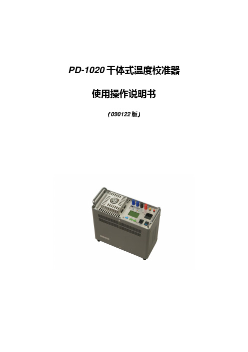
PD-1020干体式温度校准器使用操作说明书(090122版)目录1.0产品介绍……………………………………………………………………………(3)1.1产品特点1.2技术特性指标1.3环境条件1.4质量品质保证2.0初次使用 (5)2.1开箱检查2.2就位2.3检查2.4通电启动3.0 操作使用 (6)3.1功能组件说明3.2功能组件用途3.3控制器操作3.3.1按键3.3.2菜单4.0正确使用 (9)4.1仪器的标定4.1.1零点标定4.1.2满量程标定4.1.3零点及满量程综合标定调整值计算4.2推荐的几种校验方法4.2.1比对校验4.2.2槽温赋值校验4.3使用蓄电池供电及充电4.3.1电池供电4.3.2电池充电4.4使用注意事项5.0故障信息 (13)5.1声响报警5.2控制器死机5.3控温不稳定5.4机器不能加热和制冷5.5机器不加热或不制冷5.6电池充放电功能不能正常工作5.7其他故障为了使用户清楚地了解其产品技术特性、操作方法及使用注意事项,恳请您在初次启用之前阅读本使用手册。
特别告知,针对干体式温度校准器的使用方法请详细阅读“4.0正确使用”章节。
1.0产品介绍1.1产品特点公司生产PD-1020干体式温度校准器,通过精良的设计以其小型便携化的体积;简单方便的操作;便于野外及工作现场没有交流电源供电的场所可使用12V 直流供电的设计方案,特别适用于各种温度传感器、直读式就地温度表计、以及各式温度开关的维修,检查和现场校验以及短支温度探头比对校验。
使用PD—1020干体式温度校准器可以就地模拟一个实际温度源,用来对您所发现或怀疑的测温系统提供一个真实准确的验证方案。
对于要求定期校验、检查的测温系统可以免除将元件拆卸取回实验室校验的麻烦以及可能出现的差错。
当您使用干体式温度校准器时,由于其体积小,不受电源供电限制且具有快速升降温特性,会使您感到方便、迅速、准确而可靠。
由于采用了半导体加热(冷却)控温的先进设计理念,会使您在使用中感受到近乎理想化的程度。
AOZ1073AI 规格书
Rev. 1.1 September 2008
Page 3 of 15
AOZ1073
Electrical Characteristics
TA = 25°C, VIN = VEN = 12V, VOUT = 3.3V unless otherwise specified.(3)
Rating
4.5V to 16V 0.8V to VIN -40°C to +85°C 87°C/W 30°C/W
Package Thermal Resistance (ΘJC) SO-8 Package Power Dissipation (PD) @ 25°C Ambient SO-8
Note: 1. Devices are inherently ESD sensitive, handling precautions are required. Human body model rating: 1.5kΩ in series with 100pF.
Page 1 of 15
AOZ1073
Ordering Information
Part Number
AOZ1073AIL
Ambient Temperature Range
-40°C to +85°C
Package
SO-8
Environmental
Green (Halogen Free)
AGND
PGND
Absolute Maximum Ratings
Exceeding the Absolute Maximum Ratings may damage the device.
Recommend Operating Ratings
恩智浦半导体i.MX RT1020跨界处理器数据手册说明书
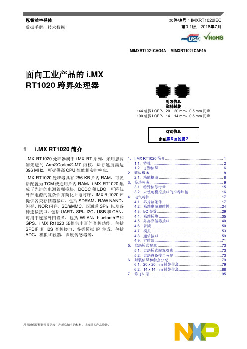
恩智浦半导体数据手册:技术数据文件编号:IMXRT1020IEC第0.1版,2018年7月MIMXRT1021CAG4A MIMXRT1021CAF4A面向工业产品的i.MXRT1020跨界处理器封装信息塑料封装144引脚LQFP,20 × 20 mm,0.5 mm间距100引脚LQFP,14 × 14 mm,0.5 mm间距订购信息参见第6页的表21 i.MX RT1020简介i.MX RT1020处理器属于i.MX RT系列,采用恩智浦先进的Arm®Cortex®-M7内核,运行速度高达396 MHz,可提供高CPU性能和实时响应。
i.MX RT1020处理器具有256 KB片内RAM,可灵活配置为TCM或通用片内RAM。
i.MX RT1020集成了先进的电源管理模块、DCDC和LDO,可降低外部电源的复杂性并简化上电时序。
IMX Rt1020还提供各类存储器接口,包括SDRAM、RAW NAND、闪存、NOR闪存、SD/eMMC、四通道SPI;以及各种连接接口,包括UART、SPI、I2C、USB和CAN,可用于连接外围设备,包括WLAN、b luetooth™和GPS。
i.MX Rt1020还提供丰富的音频功能,包括SPDIF和I2S音频接口。
各类模拟IP集成,包括ADC、模拟比较器、温度传感器等。
1. I.MX RT1020简介 (1)1.1. 特性 (2)1.2. 订购信息 (6)2. 架构概述 (8)2.1. 功能框图 (8)3. 模块列表 (9)3.1. 特殊信号考量 (15)3.2. 未使用模拟接口的推荐连接 (16)4. 电气特性 (17)4.1. 芯片级条件 (17)4.2. 系统电源和时钟 (24)4.3. I/O参数 (29)4.4. 系统模块 (35)4.5. 外部存储器接口 (40)4.6. 音频 (50)4.7. 模拟 (53)4.8. 通信接口 (59)4.9. 定时器 (71)5. 启动模式配置 (73)5.1. 启动模式配置引脚 (73)5.2. 启动设备接口分配 (73)6. 封装信息和触点分配 (79)6.1. 20 x 20 mm封装信息 (79)6.2. 14 x 14 mm封装信息 (88)7. 修订记录 (95)i.MX RT1020简介i.MX RT1020特别适合以下应用:•工业•电机控制•家用电器•IoT1.1 特性i.MX RT1020处理器基于Arm Cortex-M7 MPCore™平台,具有以下特性:•支持单Cortex-M7和−16 KB L1指令缓存−16 KB L1数据缓存−全功能浮点单元(FPU),支持VFPv5架构−支持Armv7-M Thumb指令集•集成MPU,最多16个独立保护区域•I-TCM和D-TCM总共达256 KB•目标频率为396 MHz•集成Cortex M7 CoreSight™组件用于调试•内核频率请参见19页的表11“工作范围”。
- 1、下载文档前请自行甄别文档内容的完整性,平台不提供额外的编辑、内容补充、找答案等附加服务。
- 2、"仅部分预览"的文档,不可在线预览部分如存在完整性等问题,可反馈申请退款(可完整预览的文档不适用该条件!)。
- 3、如文档侵犯您的权益,请联系客服反馈,我们会尽快为您处理(人工客服工作时间:9:00-18:30)。
General DescriptionThe AOZ1020 is a synchronous high efficiency, simple to use, 2A buck regulator. The AOZ1020 works from a 4.5V to 16V input voltage range, and provides up to 2A of continuous output current with an output voltage adjustable down to 0.8V.The AOZ1020 comes in an SO-8 packages and is rated over a -40°C to +85°C ambient temperature range.Features●4.5V to 16V operating input voltage range●Synchronous rectification: 130mΩ internal high-side switch and 65mΩ internal low-side switch●High efficiency: up to 95%●Internal soft start●Active high power good state●Output voltage adjustable to 0.8V●2A continuous output current●Fixed 500kHz PWM operation●Cycle-by-cycle current limit●Pre-bias start-up●Short-circuit protection●Thermal shutdown●Small size SO-8 packagesApplications●Point of load DC/DC conversion●PCIe graphics cards●Set top boxes●DVD drives and HDD●LCD panels●Cable modems●Telecom/Networking/Datacom equipmentFigure 1. 3.3V/2A Buck RegulatorOrdering InformationAll AOS products are offered in packages with Pb-free plating and compliant to RoHS standards.Parts marked as Green Products (with “L” suffix) use reduced levels of Halogens, and are also RoHS compliant.Please visit /web/quality/rohs_compliant.jsp for additional information.Pin ConfigurationPin DescriptionPart NumberAmbient Temperature RangePackageEnvironmentalAOZ1020AI -40°C to +85°CSO-8RoHS AOZ1020AILGreen ProductPin NumberPin NamePin Function1PGND Power ground. Electrically needs to be connected to AGND.2V IN Supply voltage input. When V IN rises above the UVLO threshold the device starts up.3AGND Reference connection for controller section. Also used as thermal connection for controller section. Electrically needs to be connected to PGND.4FB The FB pin is used to determine the output voltage via a resistor divider between the output and GND.5COMP External loop compensation pin. 6EN The enable pin is active HIGH. 7LX PWM output connection to inductor.8PGOODPower good signal output pin. It is an open drain output used to indicate the status of output voltages. This pin is internally pulled low when the output is below 90% of the nominal voltage.Block DiagramAbsolute Maximum RatingsExceeding the Absolute Maximum Ratings may damage the device.Note:1. Devices are inherently ESD sensitive, handling precautions are required. Human body model rating: 1.5k Ω in series with 100pF.Recommended Operating ConditionsThe device is not guaranteed to operate beyond the Recom-mended Operating Conditions.Note:2. The value of ΘJA is measured with the device mounted on 1-in 2 FR-4 board with 2oz. Copper, in a still air environment with T A = 25°C. The value in any given application depends on the user's spe-cific board design.ParameterRatingSupply Voltage (V IN )18VLX to AGND -0.7V to V IN +0.3V EN to AGND -0.3V to V IN +0.3VFB to AGND -0.3V to 6V COMP to AGND -0.3V to 6V PGND to AGND -0.3V to 0.3V PGOOD to AGND -0.3V to 6.0VJunction Temperature (T J )+150°CStorage Temperature (T S )-65°C to +150°CESD Ratingl (1)2.0kVParameterRatingSupply Voltage (V IN ) 4.5V to 16V Output Voltage Range0.8V to V IN Ambient Temperature (T A )-40°C to +85°CPackage Thermal Resistance (ΘJA )(2) SO-887°C/W Package Thermal Resistance (ΘJC ) SO-830°C/WPackage Power Dissipation (P D ) @25°C Ambient SO-81.15WElectrical CharacteristicsT A = 25°C, V IN = V EN = 12V, V OUT = 3.3V unless otherwise specified .(3)Note:3. Specifications in BOLD indicate an ambient temperature range of -40°C to +85°C. These specifications are guaranteed by design.SymbolParameterConditions Min.Typ.Max.UnitsV IN Supply Voltage4.516V V UVLO Input Under-Voltage Lockout Threshold V IN Rising V IN Falling4.13.7VI IN Supply Current (Quiescent)I OUT = 0, V FB = 1.2V, V EN > 1.2V 1.6 2.5mA I OFF Shutdown Supply Current V EN = 0V 110µA V FBFeedback Voltage T A = 25°C0.7880.80.812V Load Regulation 0.5%Line Regulation1%I FB Feedback Voltage Input Current 200nAENABLEV EN EN Input Threshold Off Threshold On Threshold20.6V V HYS EN Input Hysteresis 100mV MODULATORf O FrequencyT A = -40°C to +85°C350500600kHz D MAX Maximum Duty Cycle 100%D MIN Minimum Duty Cycle 6%G VEA Error Amplifier Voltage Gain 500V / V G EA Error Amplifier Transconductance 200µA / VPROTECTIONI LIMCurrent Limit2.54.0A Over-Temperature Shutdown LimitT J Rising T J Falling150100°C t SS Soft Start Interval 4msPOWER GOODV OLPG PG LOW Voltage I OL = 1mA0.5V PG Leakage1µA V PGL PG Threshold Voltage879092%V O PG Threshold Voltage Hystersis 3%t PGPG Delay Time128µsPWM OUTPUT STAGEHigh-Side Switch On-Resistance V IN = 12V V IN = 5V 97166130200m ΩLow-Side Switch On-ResistanceV IN = 12V V IN = 5V507565105m ΩTypical Performance CharacteristicsCircuit of Figure 1. T A = 25°C, V IN = V EN = 12V, V OUT = 3.3V unless otherwise specified.Light Load OperationFull Load (CCM) OperationStartup to Full Load50% to 100% Load Transient1s/di v 1s/di v100s/di vV 0.1V 20m V 2PGOOD 5lin0.5A/di V 50m lo1A/di IL 1A/di V 20EfficiencyDetailed DescriptionThe AOZ1020 is a current-mode, step down regulator with integrated high-side PMOS switch and a low-side NMOS switch. It operates from a 4.5V to 16V input voltage range and supplies up to 2A of load current. The duty cycle can be adjusted from 6% to 100% allowing a wide output voltage range. Features include enable control, Power-On Reset, input under voltage lockout, output over voltage protection, active high power good state, fixed internal soft-start and thermal shut down.The AOZ1020 is available in an SO-8 package.Enable and Soft StartThe AOZ1020 has an internal soft start feature to limitin-rush current and ensure the output voltage ramps up smoothly to regulation voltage. A soft start process begins when the input voltage rises to 4.1V and voltage on EN pin is HIGH. In the soft start process, the output voltage is typically ramped to regulation voltage in 4ms. The 4ms soft start time is set internally.The EN pin of the AOZ1020 is active HIGH. Connect the EN pin to V IN if the enable function is not used. Pulling EN to ground will disable the AOZ1020. Do not leave it open. The voltage on the EN pin must be above 2V to enable the AOZ1020. When voltage on the EN pin falls below 0.6V, the AOZ1020 is disabled. If an application circuit requires the AOZ1020 to be disabled, an open drain or open collector circuit should be used to interface to the EN pin.Power GoodThe output of Power-Good is an open drain N-channel MOSFET which supplies an active HIGH power good stage. A pull-up resistor (R3) should connect this pin to a DC power trail with maximum voltage no higher than 6V. The AOZ1020 monitors the FB voltage; when FB pin voltage is lower than 90% of the normal voltage,N-channel MOSFET turns on and the Power-Good pin is pulled LOW, which indicates the power is abnormal. Steady-State OperationUnder steady-state conditions, the converter operates in fixed frequency and Continuous-Conduction Mode (CCM).The AOZ1020 integrates an internal P-MOSFET as the high-side switch. Inductor current is sensed by amplifying the voltage drop across the drain to source of the high side power MOSFET. Output voltage is divided down by the external voltage divider at the FB pin. The difference of the FB pin voltage and reference is amplified by the internal transconductance error amplifier. The error voltage, which shows on the COMP pin, is compared against the current signal, which is sum of inductor current signal and ramp compensation signal, at the PWM comparator input. If the current signal is less than the error voltage, the internal high-side switch is on. The inductor current flows from the input through the inductor to the output. When the current signal exceeds the error voltage, the high-side switch is off. The inductor current is freewheeling through the internal low-side NMOSFET switch to output. The internal adaptive FET driver guarantees no turn on overlap of both high-side and low-side switch.Comparing with regulators using freewheeling Schottky diodes, the AOZ1020 uses freewheeling NMOSFET to realize synchronous rectification. It greatly improves the converter efficiency and reduces power loss in thelow-side switch.The AOZ1020 uses a P-Channel MOSFET as the high-side switch. It saves the bootstrap capacitor normally seen in a circuit which is using an NMOS switch. It allows 100% turn-on of the high-side switch to achieve linear regulation mode of operation. The minimum voltage drop from V IN to V O is the load current x DC resistance of MOSFET + DC resistance of buck inductor. It can be calculated by the equation below:where;V O_MAX is the maximum output voltage,V IN is the input voltage from 4.5V to 16V,I O is the output current from 0A to 2A, andR DS(ON) is the on resistance of internal MOSFET, the value is between 97mΩ and 200mΩ depending on input voltage and junction temperature.Switching FrequencyThe AOZ1020 switching frequency is fixed and set by an internal oscillator. The practical switching frequency could range from 400kHz to 600kHz due to device variation.Output Voltage ProgrammingOutput voltage can be set by feeding back the output to the FB pin by using a resistor divider network. See the application circuit shown in Figure 1. The resistor divider network includes R1 and R2. Usually, a design is started by picking a fixed R2 value and calculating the required R1 with equation below:V O_MAX V IN I O R DS ON()×–=V O0.81R1R2------+⎝⎠⎜⎟⎛⎞×=Some standard value of R 1, R 2 and most used output voltage values are listed in Table 1.The combination of R 1 and R 2 should be large enough to avoid drawing excessive current from the output, which will cause power loss.Since the switch duty cycle can be as high as 100%, the maximum output voltage can be set as high as the input voltage minus the voltage drop on upper PMOS and inductor.Protection FeaturesThe AOZ1020 has multiple protection features to prevent system circuit damage under abnormal conditions. Over Current Protection (OCP)The sensed inductor current signal is also used for over current protection. Since the AOZ1020 employs peak current mode control, the COMP pin voltage is proportional to the peak inductor current. The COMP pin voltage is limited to be between 0.4V and 2.5V internally. The peak inductor current is automatically limited cycle by cycle.When the output is shorted to ground under faultconditions, the inductor current decays very slow during a switching cycle because of V O = 0V. To prevent cata-strophic failure, a secondary current limit is designed inside the AOZ1020. The measured inductor current is compared against a preset voltage which represents the current limit, between 2.5A and 3.6A. When the output current is more than current limit, the high side switch will be turned off. The converter will initiate a soft start once the over-current condition is resolved.Power-On Reset (POR)A power-on reset circuit monitors the input voltage. When the input voltage exceeds 4.1V, the converter starts operation. When input voltage falls below 3.7V, the converter shuts down. Thermal ProtectionAn internal temperature sensor monitors the junction temperature. It shuts down the internal control circuit andhigh side PMOS if the junction temperature exceeds 150°C. The regulator will restart automatically under the control of soft-start circuit when the junction temperature decreases to 100°C.Application InformationThe basic AOZ1020 application circuit is show in Figure 1. Component selection is explained below.Input CapacitorThe input capacitor must be connected to the V IN pin and PGND pin of AOZ1020 to maintain steady input voltage and filter out the pulsing input current. The voltage rating of input capacitor must be greater than maximum input voltage plus ripple voltage.The input ripple voltage can be approximated by equa-tion below:Since the input current is discontinuous in a buckconverter, the current stress on the input capacitor is another concern when selecting the capacitor. For a buck circuit, the RMS value of input capacitor current can be calculated by:if we let m equal the conversion ratio:The relation between the input capacitor RMS current and voltage conversion ratio is calculated and shown in Figure 2 below. It can be seen that when V O is half of V IN , C IN is under the worst current stress. The worst cur-rent stress on C IN is 0.5 x I O .Figure 2. I CIN vs. Voltage Conversion RatioV O (V)R 1 (k Ω)R 2 (k Ω)0.8 1.0open 1.2 4.99101.51011.51.812.710.22.521.5103.331.1105.052.310ΔV IN I O f C IN ×-----------------1V O V IN --------–⎝⎠⎜⎟⎛⎞V O V IN--------××=I CIN_RMS I O V O V IN --------1V O V IN --------–⎝⎠⎜⎟⎛⎞×=VO V IN--------m =For reliable operation and best performance, the input capacitors must have current rating higher than I CIN_RMS at worst operating conditions. Ceramic capacitors are preferred for input capacitors because of their low ESR and high current rating. Depending on the application circuits, other low ESR tantalum capacitor may also be used. When selecting ceramic capacitors, X5R or X7R type dielectric ceramic capacitors should be used for their better temperature and voltage characteristics. Note that the ripple current rating from capacitor manu-factures are based on certain amount of life time. Further de-rating may be necessary in practical design. InductorThe inductor is used to supply constant current to output when it is driven by a switching voltage. For given input and output voltage, inductance and switching frequency together decide the inductor ripple current, which is:The peak inductor current is:High inductance gives low inductor ripple current but requires larger size inductor to avoid saturation. Low ripple current reduces inductor core losses. It also reduces RMS current through inductor and switches, which results in less conduction loss. Usually, peak to peak ripple current on inductor is designed to be 20%to 30% of output current.When selecting the inductor, make sure it is able to handle the peak current without saturation even at the highest operating temperature.The inductor takes the highest current in a buck circuit. The conduction loss on inductor need to be checked for thermal and efficiency requirements.Surface mount inductors in different shape and styles are available from Coilcraft, Elytone and Murata. Shielded inductors are small and radiate less EMI noise. But they cost more than unshielded inductors. The choice depends on EMI requirement, price and size.Table 2 lists some inductors for typical output voltage design.Output CapacitorThe output capacitor is selected based on the DC output voltage rating, output ripple voltage specification and ripple current rating.The selected output capacitor must have a higher rated voltage specification than the maximum desired output voltage including ripple. De-rating needs to be consid-ered for long term reliability.Output ripple voltage specification is another important factor for selecting the output capacitor. In a buck con-verter circuit, output ripple voltage is determined by inductor value, switching frequency, output capacitor value and ESR. It can be calculated by the equation below:where,C O is output capacitor value, andESR CO is the equivalent series resistance of the output capacitor.When low ESR ceramic capacitor is used as output capacitor, the impedance of the capacitor at the switch-ing frequency dominates. Output ripple is mainly caused by capacitor value and inductor ripple current. The output ripple voltage calculation can be simplified to:If the impedance of ESR at switching frequency dominates, the output ripple voltage is mainly decided by capacitor ESR and inductor ripple current. The output ripple voltage calculation can be further simplified to:ΔI LV Of L×----------1V OV IN--------–⎝⎠⎜⎟⎛⎞×=I Lpeak I OΔI L2 --------+=Table 2.Vout L1Manufacture5.0V3.3V1.8VUnshielded, 4.7uHLQH55DN4R7M03MURATAShielded, 4.7uHLQH66SN4R7M03MURATAShield, 5.8uHET553-5R8ELYTONEUn-shielded, 4.7uHDO3316P-472MLDCoilcraft1.2V0.8VUnshielded, 1.5uHLQH55DN1R5M03MURATAShield, 1.5uHLQH66SN1R5M03MURATAShield, 2.2uHET553-2R2ELYTONEUn-shielded, 1.5uHDO3316P-152MLDCoilcraftUn-shielded, 1.5uHDO1813P-152HCCoilcraftΔV OΔI L ESR CO18f C O××-------------------------+⎝⎠⎛⎞×=ΔV OΔI L18f C O××-------------------------⎝⎠⎛⎞×=ΔV OΔI L ESR CO×=For lower output ripple voltage across the entire operat-ing temperature range, X5R or X7R dielectric type of ceramic, or other low ESR tantalum are recommended to be used as output capacitors.In a buck converter, output capacitor current is continuous. The RMS current of output capacitor is decided by the peak to peak inductor ripple current. It can be calculated by:Usually, the ripple current rating of the output capacitor is a smaller issue because of the low current stress. When the buck inductor is selected to be very small and induc-tor ripple current is high, the output capacitor could be overstressed.Loop CompensationThe AOZ1020 employs peak current mode control for easy use and fast transient response. Peak current mode control eliminates the double pole effect of the outputL&C filter. It greatly simplifies the compensation loop design.With peak current mode control, the buck power stage can be simplified to be a one-pole and one-zero system in frequency domain. The pole is the dominant pole can be calculated by:The zero is an ESR zero due to output capacitor and its ESR. It is can be calculated by:where;C O is the output filter capacitor,R L is load resistor value, andESR CO is the equivalent series resistance of output capacitor. The compensation design is actually to shape the converter control loop transfer function to get the desired gain and phase. Several different types of compensation network can be used for the AOZ1020. In most cases, a series capacitor and resistor network connected to the COMP pin sets the pole-zero and is adequate for a stable high-bandwidth control loop.In the AOZ1020, FB pin and COMP pin are the inverting input and the output of internal error amplifier. A series R and C compensation network connected to COMP provides one pole and one zero. The pole is:where;G EA is the error amplifier transconductance, which is 200 x 10-6 A/V,G VEA is the error amplifier voltage; andC2 is compensation capacitor in Figure 1.The zero given by the external compensation network, capacitor C2 and resistor R3, is located at:To design the compensation circuit, a target crossover frequency f C for close loop must be selected. The system crossover frequency is where control loop has unity gain. The crossover is the also called the converter bandwidth. Generally a higher bandwidth means faster response to load transient. However, the bandwidth should not be too high because of system stability concern. When design-ing the compensation loop, converter stability under all line and load condition must be considered.Usually, it is recommended to set the bandwidth to be equal or less than 1/10 of switching frequency. The AOZ1020 operates at a frequency range from 400kHz to 600kHz. It is recommended to choose a crossover frequency equal or less than 40kHz.The strategy for choosing R C and C C is to set thecross over frequency with R C and set the compensator zero with C C. Using selected crossover frequency, f C,to calculate R3:where;where f C is desired crossover frequency. For best performance, f C is set to be about 1/10 of switching frequency,V FB is 0.8V,G EA is the error amplifier transconductance, which is 200 x 10-6 A/V, andG CS is the current sense circuit transconductance, which is5.64 A/VI CO_RMSΔI L12 ----------=f p112πC O R L××----------------------------------=f Z112πC O ESR CO××------------------------------------------------=f p2G EA2πC C G VEA××------------------------------------------=f Z212πC C R C××-----------------------------------=f C40kHz=R C f CV OV FB----------2πC2×G EA G CS×-----------------------------××=The compensation capacitor C C and resistor R C together make a zero. This zero is put somewhere close to the dominate pole fp1 but lower than 1/5 of selected crossover frequency. C 2 can is selected by:Equation above can also be simplified to:An easy-to-use application software which helps todesign and simulate the compensation loop can be found at .Thermal Management and Layout ConsiderationIn the AOZ1020 buck regulator circuit, high pulsing current flows through two circuit loops. The first loop starts from the input capacitors, to the V IN pin, to the LX pin, to the filter inductor, to the output capacitor and load, and then return to the input capacitor through ground. Current flows in the first loop when the high-side switch is on. The second loop starts from inductor, to the output capacitors and load, to the low-side NMOSFET. Current flows in the second loop when the low-side NMOSFET is on.In PCB layout, minimizing the two loops area reduces the noise of this circuit and improves efficiency. A ground plane is strongly recommended to connect input capaci-tor, output capacitor, and PGND pin of the AOZ1020. In the AOZ1020 buck regulator circuit, the major power dissipating components are the AOZ1020 and the output inductor. The total power dissipation of converter circuit can be measured by input power minus output power.The power dissipation of inductor can be approximately calculated by output current and DCR of inductor.The actual junction temperature can be calculated with power dissipation in the AOZ1020 and thermal imped-ance from junction to ambient.The maximum junction temperature of AOZ1020 is150°C, which limits the maximum load current capability. Please see the thermal de-rating curves for maximum load current of the AOZ1020 under different ambient temperature.The thermal performance of the AOZ1020 is strongly affected by the PCB layout. Extra care should be taken by users during design process to ensure that the IC will operate under the recommended environmental conditions.The AOZ1020A is a standard SO-8 package. Layout tips are listed below for the best electric and thermalperformance. Figure 3 illustrates a PCB layout example of the AOZ1020A.1.Do not use thermal relief connection to the V INand the PGND pin. Pour a maximized copper area to the PGND pin and the VIN pin to help thermal dissipation.2.Input capacitor should be connected as close aspossible to the V IN pin and the PGND pin.3. A ground plane is suggested. If a ground plane isnot used, separate PGND from AGND and connect them only at one point to avoid the PGND pin noise coupling to the AGND pin. 4.Make the current trace from the LX pin to L to C O tothe PGND as short as possible.5.Pour copper plane on all unused board area andconnect it to stable DC nodes, like V IN , GND or V OUT .6.The LX pin is connected to internal PFET drain. It isa low resistance thermal conduction path and the most noisy switching node. Connect a copper plane to the LX pin to help thermal dissipation. This copper plane should not be too large otherwise switching noise may be coupled to other parts of the circuit. 7.Keep sensitive signal traces far away from the LXpin.C C 1.52πR C f p 1××----------------------------------=C C C O R L×R C---------------------=P total_loss V IN I IN V O I O×–×=P inductor_loss I O 2R inductor 1.1××=T junction P total_loss P inductor_loss –()Θ×JA=2 Figure 3. AOZ1020A (SO-8) PCB LayoutPackage Dimensions, SO-8LTape and Reel DimensionsPart MarkingAs used herein:1. Life support devices or systems are devices or systems which, (a) are intended for surgical implant into the body or (b) support or sustain life, and (c) whose failure to perform when properly used in accordance with instructions for use provided in the labeling, can be reasonably expected to result in a significant injury of the user.2. A critical component in any component of a life support, device, or system whose failure to perform can be reasonably expected to cause the failure of the life support device or system, or to affect its safety or effectiveness.This datasheet contains preliminary data; supplementary data may be published at a later date. Alpha & Omega Semiconductor reserves the right to make changes at any time without notice. LIFE SUPPORT POLICYALPHA & OMEGA SEMICONDUCTOR PRODUCTS ARE NOT AUTHORIZED FOR USE AS CRITICAL COMPONENTS IN LIFE SUPPORT DEVICES OR SYSTEMS.。
