233-附件1
《国家标准》附件一废止的国家标准号及标准名称

GB/T 7315.6-1987
五氧化二钒化学分析方法 示波极谱法测定硫量
113
GB/T 7315.7-1987
五氧化二钒化学分析方法 AgDDTC分光光度法测定砷量
114
GB/T 7315.8-1987
五氧化二钒化学分析方法 原子吸收分光光度法测定氧化钾和氧化钠量
115
GB/T 8359-1987
6
GB/T 1430-1978
炭素材料硫量的测定
7
GB/T 14958-1994
气体保护焊用钢丝
8
GB/T 15011-1994
耐蚀合金冷轧(拔)无缝管
9
GB/T 1518-1979
锰矿石中镍量的测定 (极谱法)
10
GB/T 1519-1979
锰矿石中铜量的测定 (极谱法)
11
GB/T 186-1963
58
GB/T 14998-1994
高温合金环件毛坯
59
GB/T 15009-1994
耐蚀合金热轧板
60
GB/T 15010-1994
耐蚀合金冷轧薄板
61
GB/T 15012-1994
耐蚀合金冷轧带
62
GB/T 15392-1994
宽度小于700mm连续热镀锌钢带
63
GB/T 15393-1994
钢丝镀锌层
37
YB/T 3224-1988
TCN23—330A真空练泥机技术条件
38
YB/T 3225-1988
T148汽车柴油机曲轴箱技术条件
39
YB/T 4053-1991
高效喷流换热器技术条件
40
YB/T 4055-1991
(233号)关于印发《川煤集团内部审计档案管理办法》的通知1
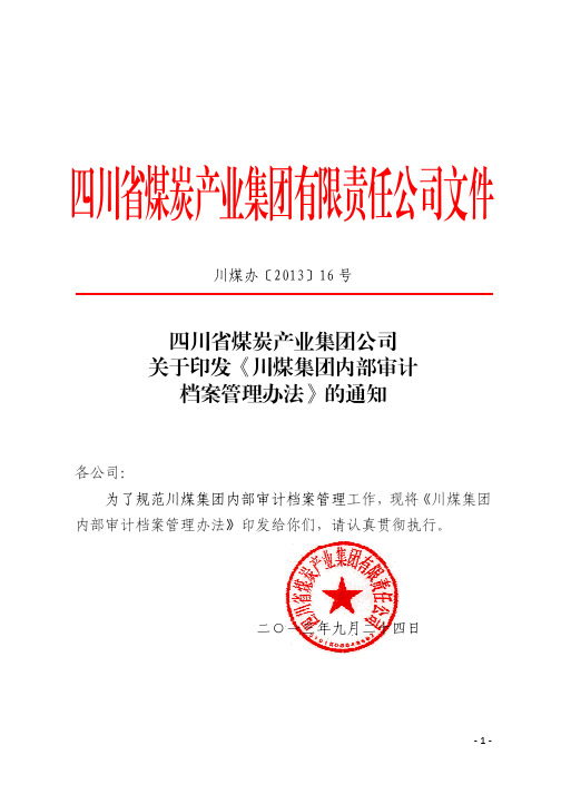
四川省煤炭产业集团有限责任公司文件川煤办〔2013〕16 号四川省煤炭产业集团公司 关于印发《川煤集团内部审计 档案管理办法》的通知各公司: 为了规范川煤集团内部审计档案管理工作,现将《川煤集团 内部审计档案管理办法》印发给你们,请认真贯彻执行。
二○一三年九月二十四日-1-川煤集团内部审计档案管理办法第一条 为了规范川煤集团内部审计档案管理,保证内部审 计档案的质量,有效地保护和利用内部审计档案,根据审计署和 国家档案局《审计机关审计档案管理规定》和其他有关规定,结 合川煤集团具体情况,制订本办法。
第二条 本办法所称内部审计档案是指内部审计部门在开展 审计活动中形成的纸质、磁质、光盘和其他介质形式存在的具有 保存价值的历史记录。
第三条 内部审计档案管理是内部审计部门收集、整理、保 管、利用、编研、统计、鉴定和移交审计档案的全套业务工作, 以及对下属单位内部审计部门审计档案管理工作的指导和监督 等活动。
第四条 内部审计部门的审计档案管理工作接受同级档案管 理部门和上级审计机构的指导和监督; 内部审计部门和档案管理 部门在各自的职责范围内开展内部审计档案管理工作。
第五条 内部审计档案应当实行集中统一保管。
内部审计部 门应当指定审计档案保管人员, 负责本部门尚未移交给档案管理 部门的审计档案保管工作。
第六条 内部审计部门和档案保管人员的职责是: (一)认真贯彻执行国家关于审计档案管理工作的法规,依 法建立本单位内部审计档案管理工作规章制度; (二) 监督检查指导本单位内部审计人员对审计文件材料的-2-立卷和归档工作; (三)组织实施内部审计档案的收集、整理、保管、利用、 编研、统计工作,如期移交应由同级档案部门保管的审计档案; (四)对下属单位内部审计档案管理工作进行指导和监督, 有计划地开展检查、总结、培训、调研等活动。
第七条 内部审计档案案卷质量的基本要求是:审计项目文 件材料应当真实、完整、有效、规范,并做到遵循文件材料的形 成规律和特点,保持文件材料之间的有机联系,区别不同价值, 便于保管和利用。
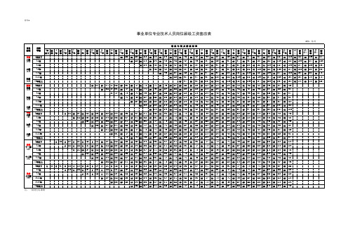
事业单位薪级工资套改表 (附件1 2 3)
583 27 613 28 29
1109 42 1154 43 1199 44 1244 45 1289 46 1334 47 1384 48 869 904 944 984 1024 1064 1109 735 767 799 834 869 904 944 643 673 703 735 767 799 555 583 613 643 673 703
1024 40 1064 41 1109 42 1154 43 1199 44 735 767 799 834 869 904 944 613 643 673 703 735 767 799 527 555 583 613 643 673 443 471 499 527 555 583 32 33 34 35 36 37 38 28 29 30 31 32 33 34 25 26 27 28 29 30 22 23 24 25 26 27
附件1
事业单位专业技术人员岗位薪级工资套改表
单位:元/月 套 改 年 限 及 薪 级 标 准 岗位 标准 正高 二级 1900 任职 年限 2年以下 3-4年 5-6年 三级 1630 7-8年 9-10年 11-12年 13年以上 2年以下 3-4年 5-6年 六级 1040 7-8年 9-10年 11-12年 13年以上 2年以下 3-4年 5-6年 九级 730 7-8年 9-10年 十级 680 11-12年 13年以上 2年以下 助理 十一级 620 3-4年 5-6年 7-8年 十二级 590 9-10年 11年以上 3年以下 4-6年 员级 十三级 550 7-9年 10-12年 13-15年 16年以上 1 80 2 91 3 4 102 113 4 5 113 125 5 6 7 125 137 151 6 7 8 137 151 165 5 1
济宁电网110千伏及以下集中式新能源并网服务指南(光伏电站)

济宁电网110千伏及以下集中式新能源并网服务指南国网济宁供电公司2021年7月前言为明确服务内容、完善服务标准、优化服务流程,向新能源企业提供优质高效的并网服务,促进网源协调发展,保障电网安全稳定运行,特编制本服务指南。
本服务指南依据《国网山东省电力公司集中式可再生能源发电项目接入电网全流程管理实施细则(试行)》(鲁电企管〔2020〕740号)、《山东电网风电场并网验收流程》(调新〔2019〕13号)、《山东电网光伏电站并网验收流程》(调新〔2019〕14号)等文件要求,对电网公司各部门在新能源并网管理中的职责进行介绍,重点说明了新能源场站(含储能)在并网前期准备、并网调度协议签订、自动化信息及继电保护联调、并网基本条件确认、并网申请等各环节的调度专业相关要求,以及向新能源企业提供的主要服务内容、工作流程概况等。
本服务指南由济宁电力调度控制中心负责解释,咨询电话:************,邮箱:272000。
目录一、济宁电网概况 (5)二、济宁供电公司各部门新能源并网管理职责介绍 (5)(一)各部门工作职责 (5)(二)并网前基本条件验收各部门主要职责 (8)(三)调控中心各专业工作职责 (9)三、新能源场站并网调控专业相关工作流程 (10)(一)并网前期工作 (10)1.消纳咨询 (10)2.接入系统方案 (10)3.初步设计 (11)4.新能源场站及设备命名 (11)5.并网调度协议签订 (12)6.培训考证 (12)(二)调度自动化系统测试联调 (12)1.开展站内单机测试 (13)2.通信调试 (13)3.提交自动化联调申请 (13)4.自动化联合调试 (14)(三)继电保护及安全自动装置联调 (14)1.站内继电保护及安全自动装置调试 (14)2.继电保护技术支持系统联调 (14)3.并网线路继电保护装置联调 (14)4.站内继电保护及安全自动装置定值复核 (14)(四)并网验收与调试 (15)1.启动送电计划 (15)2.受理并网申请 (15)3.并网基本条件确认 (15)4.启动并网调试 (16)5.正式运行 (17)四、工作联系与开展方式 (17)附件1新能源并网调度专业管理流程 (19)附件2调度专业并网用户告知书 (21)附件3签订并网调度协议所需资料及要求 (22)附件4风电场/光伏电站收资单 (23)附件5法定代表人身份证明书 (25)附件6法人授权委托书 (26)附件7新能源场站OMS账户申请书 (27)附件8自动化专业并网要求 (28)附件9新能源场站自动化专业并网流程 (31)附件10光伏电站(风电场)并网验收申请书 (37)附件11验收资料清单及要求 (38)附件13光伏电站并网前基本条件验收确认书(调控专业) (41)附件16风电场(光伏电站)并网前验收整改报错误!未定义书签。
1-233政府储备粮食仓储管理办法解读测试题答案

1-233政府储备粮食仓储管理办法解读测试题答案一、判断题(共计10题,每题2分)1、粮油仓储单位必须遵守国家法律、法规和相关管理规定,执行国家和地方粮食流通政策和粮食应急预案,贯彻国家和地方制定的仓储管理制度和标准,接受粮食行政管理部门的业务指导,配合粮食行政管理部门依法开展监督检查。
()2、《粮油仓储管理办法》是由国家粮食局于2009年12月29日颁布生效的。
()3、根据国家粮食局《粮油仓储企业规范化管理水平评价表》,无化验室的直接判定为规范化管理不达标企业。
()4、经上级主管部门批准,地方储备粮承储企业可从事与地方储备粮无关的其他粮食经营业务。
()5、储存粮油出库数量多于入库数量的溢余,可冲抵其他货位或批次粮油的损耗和损失。
()6轮换补库结束后,承储企业应当委托粮食质量检验机构对入库粮食质量进行鉴定。
()7,采用气调储粮技术储藏的原粮和成品粮,水分应不低于当地半安全水分规定。
()8、进行熏蒸作业的,应当制订熏蒸方案,并报当地粮食行政管理部门备案。
熏蒸作业中,应当在作业场地周围设立警示牌,禁止无关人员进入熏蒸作业区。
()9、《粮食卫生标准》(GB2715-2005)规定粮食农药最大残留限量中磷化物(以PH3计)应<0、1mg/kg;()判定为轻度不宜存的稻谷,应列入下一年度轮换计划安排出库。
二、单项选择题(共计20题,每题1分)1、《粮油仓储管理办法》规定,在常规储存条件下,粮油正常储存年限一般为小麦5年,稻谷和玉米年,食用油脂和豆类2年。
()A、1B、2C、3D、42、粮食储存时间在一年以上至出库,粮食保管自然损耗率累计不超过()A,0、10%B、0、15%C、0、30%D、0、20%3、库存粮油情况发生变化的,粮油仓储单位应当在个工作日内更新库存粮油货位卡和有关帐目,确保账账相符、账实相符。
()A、5B、7C、10D、154、粮油储存事故一次事故造成粮食或2吨以上20吨以下油脂损失的为较大储存事故;()A、10吨以下B、10吨以上50吨以下C、20吨以上50吨以下D、10吨以上100吨以下5、除特殊情形外,地方储备粮的轮换补库应当在储备粮出库后月内完成。
西安市科学技术局2024年创新挑战常态化企业技术需求公告(第二批)

西安市科学技术局2024年创新挑战常态化企业技术需求公告(第二批)文章属性•【制定机关】西安市科学技术局•【公布日期】2024.09.27•【字号】•【施行日期】2024.09.27•【效力等级】地方规范性文件•【时效性】现行有效•【主题分类】企业技术进步与高新技术产业化正文2024年创新挑战常态化企业技术需求公告(第二批)按照常态化创新需求挖掘工作进展,本次发布175项企业技术需求,公开“悬赏”解决方案,择优撮合转化服务,用更多科创资源滋养产业、企业发展。
现将有关事项公告如下:一、需求清单二、挑战须知(一)挑战资格凡遵守我国相关法律法规,具有一定研发能力的高等院校、研究机构、企业、自然人均可报名挑战。
(二)挑战报名请通过西安市科学技术局官网(/)、创新西安微信公众号、西安生产力促进中心微信公众号查询下载相关报名资料,于2024年10月31日前将挑战声明(附件1)和创新挑战报名表(附件2)电子版发送至****************,逾期不再受理。
三、奖励与配套政策1.为技术需求提供方提供专题项目组织、研发体系优化和匹配对接管家式服务。
2.设立优秀解决方案奖金池,对遴选出的最佳解决方案和优秀解决方案颁发荣誉证书和奖金。
3.对技术需求方按实际产生技术交易额,纳入市级科技计划项目,按技术合同登记额度的实际支出比例给予奖励。
4.对合作成功的成果转化项目,采取科技交易信用贷等多种形式给予金融支持。
联系电话:82401791、82401793、86786492附件:1.挑战声明.docx2.创新挑战报名表.docx3.创新挑战赛企业技术需求详表(第二批).rar西安市科学技术局2024年9月27日。
2024年劳动合同标的及服务内容

20XX 专业合同封面COUNTRACT COVER甲方:XXX乙方:XXX2024年劳动合同标的及服务内容本合同目录一览第一条:合同主体及签订日期1.1甲方名称及住所1.2乙方姓名及身份证号码1.3合同签订日期第二条:劳动合同期限2.1合同起始日期2.2合同终止日期第三条:标的及服务内容3.1标的概述3.2服务内容详述第四条:乙方的义务4.1工作职责4.2保密义务4.3竞业限制第五条:甲方的义务5.1提供工作条件5.2薪酬待遇5.3社会保险及福利待遇第六条:合同的变更与解除6.1合同变更条件6.2合同解除条件第七条:违约责任7.1甲方违约责任7.2乙方违约责任第八条:争议解决8.1争议解决方式8.2适用法律第九条:其他约定9.1双方的其他约定第十条:附件10.1附件列表第十一条:签字盖章11.1甲方签字(盖章)11.2乙方签字(盖章)第十二条:合同生效12.1合同生效条件12.2合同生效时间第十三条:合同副本13.1甲方保留合同副本13.2乙方保留合同副本第十四条:合同信息保密14.1保密义务14.2泄露信息的责任承担结束第一部分:合同如下:第一条:合同主体及签订日期1.1甲方名称及住所甲方名称为:×××公司住所为:×××地址1.2乙方姓名及身份证号码乙方姓名为:×××身份证号码:××××××××××××××××1.3合同签订日期本合同于××年××月××日在×××地点签订。
第二条:劳动合同期限2.1合同起始日期本合同自××年××月××日起生效。
9-80-81-70-AP系列_单机CVR233-1_快速使用手册V1.0.0中文标配(17-4-21)

9/80/81/70/AP系列单机CVR存储快速使用手册杭州海康威视数字技术股份有限公司技术热线:400-700-5998UD.6L0105B2900A01前言版权所有©杭州海康威视数字技术股份有限公司2015。
保留一切权利。
本手册的任何部分,包括文字、图片、图形等均归属于杭州海康威视数字技术股份有限公司或其子公司(以下简称“本公司”或“海康威视”)。
未经书面许可,任何单位和个人不得以任何方式摘录、复制、翻译、修改本手册的全部或部分。
除非另有约定,本公司不对本手册提供任何明示或默示的声明或保证。
本指南介绍安装、基本操作、常用处理和维护等内容,详细系统配置和操作请见《系统使用手册》。
本产品在售出三年内可提供部件更换、升级等服务。
当产品因为使用时间过老化导致产品不能使用,整机报废时,请联系产品供应商对产品进行回收处理。
关于本手册●本手册描述的产品仅供中国大陆地区销售和使用。
●本手册作为指导使用。
手册中所提供照片、图形、图表和插图等,仅用于解释和说明目的,与具体产品可能存在差异,请以实物为准。
因产品版本升级或其他需要,海康威视可能对本手册进行更新,如您需要最新版手册,请您登录公司官网查阅()。
●海康威视建议您在专业人员的指导下使用本手册。
商标声明●为海康威视的注册商标。
●本手册涉及的其他商标由其所有人各自拥有。
责任声明●在法律允许的最大范围内,本手册所描述的产品(含其硬件、软件、固件等)均“按照现状”提供,可能存在瑕疵、错误或故障,海康威视不提供任何形式的明示或默示保证,包括但不限于适销性、质量满意度、适合特定目的、不侵犯第三方权利等保证;亦不对使用本手册或使用本公司产品导致的任何特殊、附带、偶然或间接的损害进行赔偿,包括但不限于商业利润损失、数据或文档丢失产生的损失。
●若您将产品接入互联网需自担风险,包括但不限于产品可能遭受网络攻击、黑客攻击、病毒感染等,海康威视不对因此造成的产品工作异常、信息泄露等问题承担责任,但本公司将及时为您提供产品相关技术支持。
整理数量方法笔记附件1.

整理数量方法笔记附件1.
数量方法是一种通过搜寻、归类、总结和计算数据而得出结论的方法。
它能够帮助我
们更好地理解各个领域中的数据信息,并且有效地应用这些信息解决问题。
在对数量方法进行整理时,我们需要注意以下几个方面:
一、数据的收集
数据的收集是进行数量方法的第一步。
在收集数据时,我们需要明确数据的来源和数
据的类型。
数据可以来源于各种渠道,包括统计资料、调查问卷、实地调查、采访等。
数
据的类型可以分为定量数据和定性数据。
定量数据包括数字和度量,如人口、收入、温度等;而定性数据则是以文字描述为主,如品质、口感等。
二、数据的分类和总结
在完成数据收集后,我们需要对数据进行分类和总结。
分类的目的是将数据按照一定
的标准进行分组,以便于后续的分析。
总结的目的是概括数据的特征和分布情况,以更好
地理解数据所代表的现象。
数据分析是数量方法的核心。
在数据分析时,我们需要选择适当的统计方法和模型,
对数据进行计算和运算,并得出结论。
数据分析可以帮助我们更好地理解现象和问题,为
后续的决策和行动提供依据和参考。
数据的应用是数量方法的最终目的。
通过对数据的应用,我们可以制定出科学的计划
和决策,推动各种行动和项目的实现。
数据应用的过程中需要注意数据的权威性和有效性,避免数据的误解和误用。
通过以上整理,我们可以有效地应用数量方法解决各类问题,提升工作效率,取得成功。
动车组回送作业办法
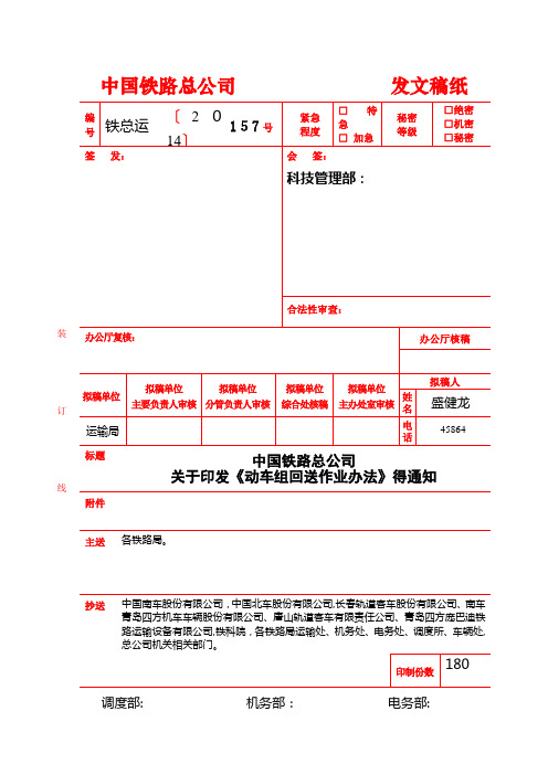
中国铁路总公司发文稿纸标题 中国铁路总公司关于印发《动车组回送作业办法》得通知附件主送各铁路局。
抄送 中国南车股份有限公司,中国北车股份有限公司,长春轨道客车股份有限公司、南车青岛四方机车车辆股份有限公司、唐山轨道客车有限责任公司、青岛四方庞巴迪铁路运输设备有限公司,铁科院,各铁路局运输处、机务处、电务处、调度所、车辆处, 调度部: 机务部: 电务部:----------------------装---------------------订---------------------线---------------------现将《动车组回送作业办法》(技术规章编号:TG/CL233—2014)印发给您们,请认真贯彻执行。
ﻬ动车组回送作业办法第一章总则第一条为规范各型动车组回送作业,确保动车组回送安全,特制定本办法。
第二条本办法适用于动车组有动力及无动力回送作业。
第三条同型短编动车组可以重联回送。
第二章回送组织第四条动车组出入厂、转属、借用等需跨局回送时,由动车组所在地铁路局向中国铁路总公司调度提出回送申请,总公司下达调度命令;局管内回送时,由动车(客车)段、造修单位向铁路局调度提出回送申请,铁路局下达调度命令。
第五条动车组回送申请应明确编组辆数、牵引总重、全长、随车机械师担当,建议回送日期时刻、回送区段、回送方式、回送要求、回送径路。
调度命令须明确乘务担当、回送方式、回送径路等.第六条动车组跨局回送径路按总公司公布得跨局回送径路执行,局管内回送径路由各铁路局自行公布。
回送径路发生变化时,须由相关路局对弓网、电务设备等匹配条件进行核准确认。
第七条动车组有动力回送时,配属局依据调度命令规定得回送径路,负责确认车载电务设备相关数据.第八条有动力回送区段超过配属局动车组司机乘务交路担当区段时,途经局应提前安排司机带道或值乘.第九条动车组一般情况下不得通过半径小于250m得曲线,且通过半径为250m得曲线时,须限速15km/h;所有动车组不得侧向通过小于9号得单开道岔与6号得对称双开道岔。
2024年度家居安装协议条款版A版

20XX 专业合同封面COUNTRACT COVER甲方:XXX乙方:XXX2024年度家居安装协议条款版A版本合同目录一览1. 协议概述1.1 协议双方1.2 协议范围1.3 协议期限2. 安装服务内容2.1 安装项目2.2 安装标准2.3 安装时间3. 安装材料及设备3.1 材料供应3.2 设备提供3.3 材料及设备质量4. 安装费用及支付方式4.1 安装费用4.2 支付方式4.3 费用调整5. 安装质量保证5.1 质量标准5.2 保修期限5.3 质量问题处理6. 双方责任及义务6.1 甲方责任及义务6.2 乙方责任及义务7. 违约责任7.1 甲方违约7.2 乙方违约8. 争议解决8.1 协商解决8.2 调解解决8.3 法律途径9. 合同的变更与解除9.1 变更条件9.2 解除条件10. 保密条款10.1 保密内容10.2 保密期限10.3 违约保密11. 合同的生效、终止与失效11.1 生效条件11.2 终止条件11.3 失效条件12. 法律适用及争议解决12.1 法律适用12.2 争议解决13. 其他约定13.1 安装前的准备工作13.2 安装过程中的沟通与协调13.3 安装后的售后服务14. 附件14.1 安装项目明细表14.2 材料及设备清单14.3 付款凭证及验收报告第一部分:合同如下:第一条协议概述1.1 协议双方双方经友好协商,就甲方委托乙方进行家居安装的相关事宜,达成如下协议。
1.2 协议范围本协议范围包括但不限于甲方家居的__________(具体安装项目)、__________(具体安装项目)等安装工作。
1.3 协议期限本协议自双方签字之日起生效,有效期为2024年1月1日至2024年12月31日。
第二条安装服务内容2.1 安装项目乙方负责按照甲方提供的家居安装方案和标准,进行__________(具体安装项目)的安装工作。
2.2 安装标准安装工作应严格按照__________(国家标准、行业标准、甲方要求)进行,确保安装质量符合相关标准。
EE233电路理论实验1:RC电路说明书

EE 233 Circuit TheoryLab 1: RC CircuitsTable of Contents1Introduction (1)2Precautions (1)3Prelab Exercises (2)3.1The RC Response to a DC Input (2)3.1.1Charging RC Circuit (2)3.1.2Discharging RC Circuit (3)3.1.3Square Wave Input (3)3.1.4Multiple-stage RC Circuits (3)3.2The RC Response to a Sinusoidal Input (4)3.2.1Time-domain RC Response (4)3.2.2Frequency-domain RC Response (5)4Experimental Procedure and Data Analysis (6)4.1The RC Response to a DC Input (6)4.1.1Square Wave Input Analysis (6)4.1.2Time Constant Measurement (7)4.2The RC Response to a Sinusoidal Input (7)5Reference Material (9)5.1RC Step Response and Timing Parameters (9)5.2Elmore Delay Estimation (10)5.3Frequency Response of a Circuit System (10)5.4Parameter Extraction via Linear Least-Squares-Fit Technique (11)Table of FiguresFigure 3.1.1: Single-stage RC circuit. (2)Figure 3.1.2: Two-stage RC circuit. (4)Figure 3.1.3: Three-stage RC circuit. (4)Figure 3.2.1: An RC circuit with the output over the resistor. (5)Figure 4.1.1: RC circuit for lab experiment. (6)Figure 5.1.1: Timing parameters of signal waveforms. (9)Figure 5.2.1: N-stage RC circuit delay estimation. (10)1 IntroductionThis lab is designed to teach students methods for characterizing circuit systems, and more specifically, an RC circuit system. This lab will also familiarize students with the test bench instruments used in this class by having them use the equipment to analyze some fundamental response trends of step and sinusoidal input functions for an RC circuit.A circuit system can be pictured as a box with inputs and outputs, and the characteristics of this system can be represented by its input and output signals, e.g. voltage and current. A signal contains three parameters: magnitude, frequency, and phase. Any change of these parameters in the input signal will affect the output signal.The RC circuit has many interesting characteristics while staying one of the most basic circuit systems. This lab is going to allow students to observe these characteristics and teach them how to analyze the output signals with changes in input magnitude or frequency.This lab is split into a prelab exercise and hardware implementation. Submit one prelab report and one lab report per group, with the members’ names are clearly written on the front page. There is no template for the prelab report, and the lab report template is available on Canvas. These reports must be in pdf format. There are multiple apps, including CamScanner, for Apple and Android phones that turn photos into pdf’s. 2PrecautionsNone of the devices used in this set of experiments are particularly static sensitive; nevertheless, you should pay close attention to the circuit connections and the polarity of the power supplies, function generator, and oscilloscope inputs.3 Prelab Exercises3.1 The RC Response to a DC Input3.1.1 Charging RC CircuitThe differential equation for v out (t) is the most fundamental equation describing the RC circuit, and it can be solved if the input signal v in (t) and an initial condition are given.Figure 3.1.1: Single-stage RC circuit. Now suppose the input signal v in (t) has been zero for a long time, and then is changed to V o , a positive constant, at time t =0. The input signal is then a step function, which means:v in (t )=V o u(t)={0, t <0V o , t ≥0The initial condition for v out (t ) is needed to solve the differential equation. The output voltage should be zero when t <0, since there is no input until t =0. Thus, the initial condition for v out (t ) is v out (0)=0.Download Lab1_Prelab.m and lab1plot.m from the Canvas webpage, making sure they are in the same folder on your computer. Suppose V o =5V, R =10k Ω, and C =0.01µF.To do this, open Lab1_Prelab.m using Matlab (there is no need to open the other file) and read the developer comments about how to use the lab1plot function. Run the script, select “Change Folder” if the warning appears, and the plot for Prelab #3 should appear. You are not expected to know how to use Matlab in this course, so feel free to ask the TA for assistance if you have difficulty using the script.3.1.2 Discharging RC CircuitYou have now analyzed t he RC circuit’s step response, and you also have a general idea of what this response looks like by plotting it with the input voltage. Now suppose the input signal has been V o , a positive constant, for a long time before being changed to zero at t =0, which meansv in (t )=V o u(−t)={V o , t <00, t ≥03.1.3 Square Wave InputIf the input signal is turned on and off periodically then it becomes a square wave. Suppose the period of this square wave is T , and its duty cycle (the ratio of how long the square wave is on vs. how long it’s off) is 50%. If half of the period, T/2≫RC then the output voltage goes to its limit before the input changes. Example: If T =10RC , the ratio V out (T/2)−V out (0)V 0=V 0exp (−5)V=0.67%<1%. So the change of output voltage is almost equal to the change of the input voltage, andit means the output voltage is close to its limit.Refer to Reference 5.1 to answer Prelab #6.When deriving the expressions, notice that these timing parameters are independent of the input voltage. 3.1.4 Multiple-stage RC CircuitsRefer to Reference 5.2 Elmore Delay Estimation to answer Prelab #8.Figure 3.1.2: Two-stage RC circuit.Figure 3.1.3: Three-stage RC circuit.3.2The RC Response to a Sinusoidal Input3.2.1Time-domain RC ResponseWhile the input square wave changes the magnitude of the signal, exploration of the RC response to an AC signal can show more interesting characteristics of the RC circuit. Looking back on Figure 3.1.1, the single-stage RC circuit, suppose we are using a sinusoidal wave as an input signal, v in(t)=V o cos(ωt), where ω is the angular frequency of the signal.This differential equation is the fundamental equation describing the RC circuit system. The solution for the steady-state output voltage isv out(t)=V o1+R2C2ω2[cos(ωt)+RCωsin(ωt)]This solution shows that v out(t) is a function of the signal’s frequency f and time t. The relationship between angular frequency ω and signal frequency f is ω=2πf.Suppose V o =1V (notice it’s different), f =1kHz, R =10k Ω, and C =0.01µF.3.2.2 Frequency-domain RC ResponseNow consider the solution for v out (t ) with the signal’s frequency f being the independent variable. The output voltage is a sinusoidal wave with the same frequency as the input voltage, and its magnitude is given by|V out (f )|=V o √1+4π2R 2C 2f 2Suppose V o =1V, R =10k Ω, and C =0.01µF. Notice that the frequency-domain plot’s x -axis is logarithmic, that is, each division is 10 times greater than the previous. This frequency-domain plot will become very important in subsequent labs, where you will use it to design filters for your audio mixer.Now consider another RC system in Figure 3.2.1,in which the output voltage is over the resistor,rather than the capacitor.The output voltage is now the input signal minusthe voltage over the capacitor, and its magnitude isgiven bySuppose V o =1V, R =10k Ω, and C =0.01µF.Figure 3.2.1: An RC circuit with the output over the resistor. |V out (f )|=o +4π2R 2C 2f 24 Experimental Procedure and Data Analysis4.1 The RC Response to a DC Input4.1.1 Square Wave Input AnalysisBuild the circuit in Figure 4.1.1 and set thefunction generator to provide a square wave inputas follows:a) The period T ≥4ms (to ensure that T ≫RC ).This value of T guarantees that the output signalhas sufficient time to reach a final value beforethe next input transition. Record your value ofT . b) The minimum voltage is 0V and maximumvoltage is 5V. Note that you may need to manually set the offset to achieve this waveform. Use the oscilloscope to display this waveform on Channel 1 to verify that the amplitude is correct. We use these amplitudes since it they are common in computer systems (false = 0V, true = 5V).Use Channel 2 of the oscilloscope to display the output voltage over the capacitor. Adjust the time base to display 3 complete cycles of the signals. Capture the output from the scope display with both the waveforms and the measured values. Turn this oscilloscope waveform in as part of your lab report.Using the oscilloscope ’s Cursor menu, record the period T of the input signal, as well as the maximum and minimum values of the output signal. Then measure the time value of the 10% point of V out , the time value of the 90% point of V out , and the time value of the 50% point of V out .Note: Instructions for using the lab equipment are found in Lab Equipment.pdf , on the Canvas webpage. Percent error is defined as:PE =|actual value −theoretical value|theoretical value ×100%Now clear all the oscilloscope measurements. Use the measurement capability of the oscilloscope to measure the rise time of v out (t), the fall time of v out (t), and the two delay times t PHL and t PLH .Figure 4.1.1: RC circuit for lab experiment.4.1.2Time Constant MeasurementThe time constant τ=RC is one of the most important characteristics of RC circuit, and its value can be extracted from measured data.To measure the time constant τ, use the oscilloscope’s Cursor menu to measure the voltage and time values at 10 points on the v out waveform during one interval when v out either rises or falls with time (pick one interval only). Note that the time values should be referred to time t=0 at the point where the input signal rises from 0V to 5V or falls from 5V to 0V. Record the 10 measurements.Explanation: Consider the ratio of |v out−v in| and high voltage V0. It isRatio(t)=|v out(t)−v in||V0|=e−tτand it can be calculated by measured data. So the function ln (Ratio(t)) is linearaccording to time, and the slope is −1τ. Read Reference 5.4 for more information.Now build two-stage and three-stage RC circuits and measure time constant τtwo−stage and τthree−stage using the same methods as the single stage circuit analysis. Record all your measurements.4.2The RC Response to a Sinusoidal InputRebuild the circuit in Figure 4.1.1 and set the function generator to provide a sinusoidal input with:a) An amplitude of 1V, which means V pk−pk=2Vb) A frequency of 1kHz.Connect Channel 1 to the input voltage and Channel 2 to the voltage over the capacitor as the output. Display the input and output voltages simultaneously on the oscilloscope in 3 complete cycles. Capture the output from the scope display with both the waveforms and the measured values. Turn this oscilloscope waveform in as part of your lab report.Now measure the RC response to sinusoidal signals with various frequencies. Keep the input amplitude at 1V, but sweep the frequency from the starting input frequency of 10Hz, varying it using a 1-2-5 sequenceup to 1MHz (i.e. set input frequency to 10Hz, 20Hz, 50Hz, 100Hz, 200Hz … up to 1MHz). Record the amplitudes of the output signals.Once done, switch the locations of the resistor and capacitor and change the output to be the voltage over the resistor. Set the function generator to provide a sinusoidal wave input with 1V amplitude. As before, sweep the frequency starting from 10Hz using the 1-2-5 sequence up to 1MHz. Record the amplitudes of the output signals.5Reference Material5.1RC Step Response and Timing ParametersThe step response of a simple RC circuit, illustrated in Figure 5.1.1, is an exponential signal with time constant τ=RC. Besides this timing parameter, four other timing parameters are important in describing how fast or how slow an RC circuit responds to a step input. These timing parameters are marked in Figure5.1.1, as three voltage levels:a) The 10%-point is the point at which the output voltage is 10% of the maximum output voltage.b) The 50%-point is the point at which the output voltage is 50% of the maximum output voltage.c) The 90%-point is the point at which the output voltage is 90% of the maximum output voltage.Figure 5.1.1: Timing parameters of signal waveforms.The three timing parameters are defined as follows:a) Rise time: the time interval between the 10%-point and the 90%-point of the waveform when the signal makes the transition from low voltage (L) to high voltage (H). Notation: t r.b) Fall time: the time interval between the 90%-point and the 10%-point of the waveform when the signal makes the transition from high voltage (H) to low voltage (L). Notation: t f.c) Delay time (or propagation delay time): the time interval between the 50%-point of the input signal and the 50%-point of the output signal when both signals make a transition. There are two delay times depending on whether the output signal is going from L to H (delay notation t PLH) or from H to L (delay notation t PHL). The subscript P stands for “propagation.”Note that the rise time and the fall time are defined using a single waveform (the output waveform), while the delay time is defined between two waveforms: the input waveform and the corresponding output waveform.5.2Elmore Delay EstimationFigure 5.2.1 depicts a multi-element configuration. The resistor R1 in this figure charges all N capacitors downstream of its own position. The Elmore estimated delay τ1 from point x0 to x1 is thereforeτ1=R1∑C mNm=1Resistor R2 charges only capacitors numbered 2 through N, so the estimated delay from point x1 to x2 isτ2=R2∑C mNm=2Working down the row, the total delay for the whole circuit is then estimated as:τ=∑R nNn=1∑C m Nm=nFigure 5.2.1: N-stage RC circuit delay estimation.5.3Frequency Response of a Circuit SystemAn analog circuit system has different responses for sine waves with different frequencies. The magnitude of the output voltage always changes in terms of frequencies if the magnitude of the input sine wave stays the same. Therefore, the frequency response is the quantitative measure to characterize the system. Since any input signal can be regarded as the sum of a set of sinusoidal waves, the output signal will have different responses to input waves with the set of frequencies. If the circuit has high magnitude for low frequencies, and close to zero magnitude for high frequencies, the high frequencies will be removed by the circuit in the output signal, and vice versa.The frequency response is one of the main characteristics of the system, and you will explore methods of analyzing the frequency response in the following labs.5.4Parameter Extraction via Linear Least-Squares-Fit TechniqueThe important parameters of V out(t) are the maximum amplitude and the time constant τ. The maximum amplitude is easily measured by using the oscilloscope. Measuring the time constant directly and accurately is more difficult, since the waveform is an exponential function of time. A linear least-squares-fit procedure can be used in the lab to extract the time constant from measured voltage and time values as follows.The equation for V out(t) during the time interval when V out(t) falls with time, which you can write based on what you learned in prerequisite courses, can be manipulated to provide a linear function in terms of the time t. The slope of this line is then used to extract the time constant τ.Alternatively, the equation for V out(t) during the time interval when V out(t) rises with time can also be manipulated to provide a linear function in terms of the time t. The slope of this line is then used to extract the time constant τ.In the lab, you will measure a set of data points (t,V out). These values, after the appropriate manipulation as above, can be used to plot a straight line, whose slope is a function of τ. You can use any procedure or a calculator to plot and extract the slop. The slope value will then be used to calculate the time constant τ. Make sure you understand this procedure and be ready to use it in the lab. Note that the more points you measure, the more accurate the extracted value for τ.。
关于GB_T14233_1存在问题的探讨

.36《中国医疗器械信息》2006年第12卷第9期 V ol.12 No.9文章编号:1006-6586(2006)09-00 中图分类号:R197 文献标识码:B收稿日期:2006-06-07作者简介:辛凤鲜,高级工程师,天津哈娜好医材有限公司试验课课长GB/T14233.1《医用输液、输血、注射器具检验方法 第一部分:化学分析方法》是我国一次性使用医用高分子塑料制品化学性能通用的检验方法,2005年新颁布的输液器、输血器等的国家标准中仍然引用此标准作为其化学性能分析方法。
由此可见此标准在一次性使用医疗器械检验方面占有重要地位。
为了使此标准更加严谨,更加经得起推敲,现将该标准中存在的问题提出来和同行们共同探讨。
1 关于使用试剂的级别在GB/T14233.1 3.2中指出“本标准中所用试剂若无特殊规定均为分析纯”。
但是,我们发现标准中有多处应该使用基准级试剂而却未被注明,这种情况有如下几处:1.1在GB/T14233.1 5.2.1.2 b) 中,0.05mol/l 草酸钠溶液的配制应该使用基准级草酸钠试剂。
1.2在GB/T14233.1 5.3.2 a) 中,氯化钠标准贮备液的配制应该使用基准级氯化钠试剂。
1.3在GB/T14233.1 5.6.1.2 d) 中,铅标准贮备液的配制应该使用基准级硝酸铅或者专用的铅标准物试剂;1.4在GB/T14233.1 5.9.2.1.2 g) 中,锌标准贮备液的配制应该使用基准级氧化锌试剂。
1.5在GB/T14233.1 5.9.2.2.2 g) 中,铅标准贮备液的配制应该使用基准级硝酸铅配制。
在1.1中,0.05mol/l 草酸钠溶液在这里应该使用标准溶液。
如果标准溶液直接配制而不加以标定时必须使用基准级试剂,这样才能保证溶液浓度的准确。
在1.2~1.5中所述的标准贮备液也必须使用基准级试剂进行配制,分析纯试剂的纯度无法保证标准贮备液浓度准确。
2 关于可操作性2.1在GB/T14233.1 5.2.1.3 0.02mol/l 高锰酸钾标准溶液的标定中,“取105˚C 下干燥至恒重的基准草酸钠约0.2克,精确称重,加入100ml 硫酸溶液(92+8) ,搅拌使之溶解。
圆形 233-1
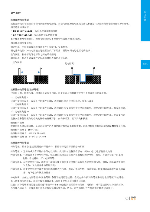
电气参数WAIN 16-06连接器的电压等级连接器的电压等级取决于空气间隙和爬电距离。
对空气间隙和爬电距离的测试和评定与以前的绝缘等级相比有少许变化。
相关适用标准如下:·IEC 60664-1/11.92 低压系统设备绝缘等级·DIN VDE 0110/4.97 低压系统设备绝缘等级鉴于使用和环境的要求,绝缘等级包括设备绝缘特性的选择(如连接器)。
相关概念的简要说明:额定电压:电压值直接由连接器生产厂家给出,仅供参考。
额定冲击电压:冲击电压值由连接器生产厂家给出,指短时间内过电压时的绝缘。
空气间隙:指相邻的导电部件之间的最小距离。
爬电距离:指两个导线部件之间绝缘材料表面的最短距离。
连接器的电压等级(绝缘等级)过电压分类:按照标准,将过电压划分为四类。
以下针对与连接器有关的三个类别做出简要说明。
连接器的污染等级污染等级:设备(如连接器)所处的环境条件,按照标准污染等级被分为四级。
空气间隙爬电距离一 过电压类别 I仪器中使用的设备,或设备中的部件(比如:连接器)不允许过电压出现。
如低压设备。
二 过电压类别 II仪器中使用的设备,或设备中的部件(比如:连接器)不应受到雷电中过电压的影响,即使是瞬间过电压。
如家用电器。
三 过电压类别 III仪器中使用的设备,或设备中的部件(比如:连接器)不应受到雷电中过电压的影响,即使是瞬间过电压。
但需要考虑设备安全和使用或与此有关的网络的特殊要求。
如保护装置、接下开关和插座。
绝缘材料组别对爬电电距进行测试时,必须注意到生产者的绝缘材料的漏电起痕指数。
绝缘材料按照漏电起痕指数CTI被分为三组:绝缘材料组别 I 600≤ CTI绝缘材料组别 II 400≤ CTI <600绝缘材料组别 III 175≤ CTI <400污染等级1:无污染或只有干燥的非导电性污染,此污染对设备没有影响。
例如:电气/电子测量仪内部污染等级2:一般情况下非导电性污染,偶尔会出现因为凝结而产生的暂时的导电性。
化学药品注册申报资料指南(试行)(注册分类1、2、3、5.1)
附件1化学药品注册申报资料指南(试行)(第一部分注册分类1、2、3、5.1类)可编辑范本目录一、适用范围 (3)二、基本要求 (3)(一)申请表的整理 (3)(二)申报资料的整理 (4)三、申请表 (8)(一)《药品注册申请表》 (8)(二)《小型微型企业收费优惠申请表》 (14)四、申报资料 (15)(一)申报资料项目 (15)(二)申报资料要求 (18)五、其他 (24)附件:1.申报资料袋封面格式 (25)2.申报资料项目封面格式 (27)3.申报资料项目目录 (28)4.化学药品1、2、3、5.1类注册申报资料自查表 (29)可编辑范本化学药品注册申报资料指南(试行)第一部分注册分类1、2、3、5.1类一、适用范围化学药品注册分类1、2、5.1类临床试验/新药生产(含新药证书)/上市申请;化学药品注册分类3类仿制药申请。
二、基本要求(一)申请表的整理1.种类与份数要求药品注册申请表、申报资料情况自查表、小型微型企业收费优惠申请表(如适用)各四份,一份为原件;药品研制情况申报表(如适用)、药品注册生产现场检查申请表(如适用)各四份,三份为原件。
2.依据《关于启用新版药品注册申请表报盘程序的公告》,申请表的填报须采用国家食品药品监督管理总局统一发布的填报软件,提交由新版《药品注册申请表报盘程序》生成的电子及纸质文件。
(确认所用版本为最新版[以最新发布的公告为准],所生成的电子文件的格式应为RVT文件。
各页的数据核对码必须一致,并须与提交的电子申请表一致,申请表及自查表各页边缘应加盖所有申请人或注册代理机构骑缝章。
)3.填写应当准确、完整、规范,不得手写或涂改,并应符合可编辑范本填表说明的要求。
(二)申报资料的整理1.数量与装袋方式2套完整申请资料(至少1套为原件)+1套综述资料(含概要及研究汇总表)复印件,每套装入相应的申请表。
2.文字体例及纸张2.1字体、字号、字体颜色、行间距离及页边距离2.1.1字体中文:宋体英文:Times New Roman2.1.2字号中文:不小于小四号字,表格不小于五号字;申报资料封面加粗四号;申报资料目录小四号,脚注五号字。
- 1、下载文档前请自行甄别文档内容的完整性,平台不提供额外的编辑、内容补充、找答案等附加服务。
- 2、"仅部分预览"的文档,不可在线预览部分如存在完整性等问题,可反馈申请退款(可完整预览的文档不适用该条件!)。
- 3、如文档侵犯您的权益,请联系客服反馈,我们会尽快为您处理(人工客服工作时间:9:00-18:30)。
附件1
浙江省高校重大科技攻关项目
(人文社科重大研究项目)
申请书
项目名称:
申报单位:
通讯地址(邮编):
联系电话(传真):
项目负责人(签名):
申请日期:
浙江省教育厅制
二○○九年制
填写说明
1、封面的“项目负责人”须由本人签名。
2、“出国情况”请说明国别、境外停留时间。
3、表格用A4纸打印。
4、“研究类别”含义:
基础研究:指为获得关于现象和可观察事实的基本原理及新知识而进行的实验性和理论性工作,它不以任何专门或特
定的应用或使用为目的。
应用研究:指为获得新知识而进行的创造性的研究,它主要是针对某一特定的实际目的或目标。
试验发展:指利用从科学研究和实际经验中所获得的现有知识、生产新材料、新产品、新装置、新流程和新方法,或
对现有的材料、产品、装置、流程、方法进行本质性
的改进而进行的系统性工作。
推广应用、科技服务:指与研究与发展活动相关并有助于科学技术知识的产生、传播和应用的活动。
