VI-JNNCY中文资料
LabVIEW
第一章LabVIEW简介LabVIEW是美国国家仪器公司(National Instruments Co)开发的一种图形化的编程环境。
其名称含义为实验室虚拟仪器工作平台(Lab oratory V irtual I nstrument E ngineering W orkbench)。
作为一种方便的数据采集和仪器控制开发软件,它可工作于Macintoshe 、Sun SPARC工作站、HP9000/700系列工作站以及PC机等各种机型,可运行于Windows 3.1、Windows9x/2000、Windows NT、UNIX等多系统下,是一种灵活有效的仪器控制和数据分析软件系统。
LabVIEW程序使用虚拟仪器(V irtual I nstrument,缩写为VI)的概念。
它是指一台计算机和连接外部的端口(计算机的COM口,LPT口或内插板)在软件控制下可完全模拟替代传统的仪器。
因VI功能完全是由软件定义,故在硬件系统不变的情况下,用户可通过软件开发自行改变或扩充仪器的功能,实现自己的特殊要求,或用一套硬件系统实现多种仪器的功能,从而使虚拟仪器VI不但比传统仪器更灵活有效,而且也更经济。
VI的核心就是LabVIEW程序,所以在LabVIEW中,所有程序均称之为VI程序,不管它是否通过端口和外界进行通讯。
每个VI程序均可作为一个功能模块被重复使用,因而使用LabVIEW来开发和扩展程序极为方便。
LabVIEW编程语言同常规的程序语言不同,它采用更易使用和理解的图形化程序语言-G语言(Graphical programming language)。
G语言使用图标代替常规的一条或一组语句来实现一个功能,通过各功能图标间的逻辑连接实现程序功能。
其编程过程不是书写一行行语句,而是连接一个个代表一定功能的图标,其程序编制过程简单,不涉及复杂功能实现的算法,易于掌握。
同时,因为其编程过程基于可重复使用的功能模块,故可方便地使用由专业人员编制提供的专业级别的功能模块,开发出专业水平的程序。
Labview外文翻译(带中文对照)
LabVIEWLabVIEW is a highly productive graphical programming language for building data acquisition an instrumentation systems.With LabVIEW, you quickly create user interfaces that give you interactive control of your software system. To specify your system functionality,you simply assemble block diagrams - a natural design notation for scientists and engineers. Tis tight integration with measurement hardware facilitates rapid development of data acquisition ,analysis,and presentation bVIEW contains powerful built -in measurement analysis and a graphical compiler for optimum performance. LabVIEW is available for Windows 2000/NT/Me/9x, Mac OS, Linux, Sun Solaris, and HP-UX, and comes in three different development system options.Faster DevelopmentLabVIEW accelerates development over traditional programming by 4 to 10 times! With the modularity and hierarchical structure of LabVIEW, you can prototype ,design, and modify systems in a short amount of time. You can also reuse LabVIEW code easily and quickly in other applications.Better InvestmentUsing a Lab VIEW system, each user has access to a complete instrumentation laboratory at less than the cost of a single commercial instrument. In addition, user configurable LabVIEW systems are flexible enough to adapt to technology changes, resulting in a better bong-term investment.Optimal PerformanceAll LabVIEW applications execute at compiled speed for optimal performance. With the LabVIEW Professional Development System or Application Builder, you can build stand-alone executables or DLLs for secure distribution of your code. You can even create shared libraries or DLLs to call LabVIEW code from other programming languages.Open Development EnvironmentWith the open development environment of LabVIEW, you can connect to other applications through ActiveX, the Web, DLLs, shared libraries, SQL(for databases), DataSocket, TCP/IP,and numerous other e LabVIEW to quickly create networked measurement and automation systems that integrate the latest technologies in Web publishing and remote data sharing. LabVIEW also has driver libraries available for plug-in data acquisition, signal conditioning , GPIB,VXI,PXI, computer-based instruments,serial protocols, image acquisition, and motion control. In addition to the LabVIEW development systems, National Instruments offers a variety of add-on modules and tool sets that extend the functionality of LabVIEW .This enables you to quickly build customizable, robust measurement and automation systems.LabVIEW Datalogging and Supervisory Control ModuleFor high channel count and distributed applications, the LabVIEW Datelogging and Supervisory Control Module provides a complete solution. This module delivers I/O management, event logging and alarm management, distributed logging, historical and real-time trending, built-in security, configurable networking features, OPC device connectivity, and over 3,300 built-in graphics.LabVIEW Real-TimeFor applications that require real-time performance, National Instruments offers LabVIEWReal-Time. LabVIEW Real-Time downloads standard LabVIEW code to a dedicated hardware target running a real-time operating system independent from Windows.LabVIEW Vision Development ModuleThe LabVIEW Vision Development Module is for scientists, automation engineers,and technicians who are developing LabVIEW machine vision and scientific imaging applications. The LabVIEW Vision Development Module includes IMAQ Vision, a library of vision functions, and IMAQ Vision Builder, an interactive environment for vision applications. Unlike any other vision products, IMAQ Vision Builder and IMAQ Vision work together to simplify vision software development so that you can apply vision to your measurement and automation applications.Countless ApplicationsLabVIEW applications are implemented in many industries worldwide including automotive, telecommunications, aerospace, semiconductor, electronic design and production, process control, biomedical, and many others, Applications cover all phases of product development from research to design to production and to service. By leveraging LabVIEW throughout your organization you can save time and money by sharing information and software.Test and MeasurementLabVIEW has become an industry-standard development tool for test and measurement applications. With Test Stand, LabVIEW-based test programs, and the industry's largest instrument driver library, you have a single, consistent development and execution environment for your entire system.Process Control and Factory AutomationLabVIEW is used in numerous process control and factory automation applications.Many scientists and engineers look to LabVIEW for the high speed, high channel count measurement and control that graphical programming offers.For large, complex industrial automation and control applications, the LabVIEW Data logging and Supervisory Control Module provides the same graphical programming as LabVIEW, but is designed specifically for monitoring large numbers of I/O points, communicating with industrial controllers and networks, and providing PC-based control.Machine Monitoring and ControlLabVIEW is ideal for machine monitoring and predictive maintenance applications that need deterministic control, vibration analysis, vision and image processing, and motion control. With the LabVIEW platform of products including LabVIEW Real-Time for real-time deterministic control and the LabVIEW Data logging and Supervisory Control Module, scientists and engineers can create powerful machine monitoring and control applications quickly and accurately.Research and AnalysisThe integrated LabVIEW measurement analysis library provides everything you need in an analysis package. Scientists and researchers have used LabVIEW to analyse and compute real results for biomedical, aerospace, and energy research applications, and in numerous other industries. The available signal generation and processing, digital filtering, windowing, curve-fitting, For specialized analysis, such as joint time-frequency analysis, wavelet,and model-based spectral analysis, LabVIEW offers the specially designed Signal Processing Toolset.The Sound and Vibration Toolset offers octave analysis, averaged and nonaveraged frequency analysis, transient analysis, weighted filtering, and sound-level measurement, and more.Draw Your Own SolutionWith LabVIEW, you build graphical programs called virtual instruments (VIs) instead of writing text-based programs. You quickly create front panel user interfaces that give you the interactive control of your system. To add functionality to the user interface, you intuitively assemble block diagrams- a natural design notation for engineers and scientists.Create the Front PanelOn the front panel of your VI, you place the controls and data displays for your system by selecting ob jects from the Controls palette, such as numeric displays, meters, gauges, thermometers, LEDs, charts,and graphs.When you complete and run your VI,you use the front panel to control your system whether you move a slide, zoom in on a graph, or enter a value with the keyboard.Construct the Graphical Block DiagramTo program the VI, you construct the block diagram without worrying about the syntactical details of text-based programming languages. You do this by selecting objects (icons) from the Functions palette and connecting them together with wires to transfer data among block diagram objects. These objects include simple arithmetic functions, advanced acquisition and analysis routines, network and file I/O operations, and more.Dataflow ProgrammingLabVIEW uses a patented dataflow programming model that frees you from the linear architecture of text-based programming languages. Because the execution order in LabVIEW is determined by the flow of data between nodes,and not by sequential lines of text,you can create block diagrams that execute multiple operations in parallel. Consequently, LabVIEW is a multitasking system capable of running multiple execution threads and multiple VIs in parallel.Modularity and HierarchyLabVIEW VIs are modular in design, so any VI can run by itself or as part of another VI. You can even create icons for your own VIs, so you can design a hierarchy of VIs that serve as application building blocks. You can modify, interchange, and combine them with other VIs to meet your changing application needs.Graphical CompilerIn many applications, execution speed is critical. LabVIEW is the only graphical programming system with a compiler that generates optimized code with execution speeds comparable to compiled C programs. You can even use the LabVIEW profiler to analyse and optimize time-critical operations. Consequently, you increase your productivity with graphical programming without sacrificing execution speed.Measurements and MathematicsLabVIEW includes a variety of other measurement analysis tools. Examples include curve fitting, signal generation, peak detection, and probability and statistics. Measurement analysis functions can determine signal characteristics such as DC/RMS levels, total harmonic distortion (THD),impulse response, frequency response, and cross-power spectrum. LabVIEW users can also deploy numerical tools for solving differential equations, optimization, root finding, and other mathematical problems.In addition, you can extend these built-in capabilities by entering MATLAB or HIQ scripts directly in your LabVIEW programs. For charting and graphing, you can rely on the built-in LabVIEW 2D and 3D visualization tools. 2D tools include features such as autoscaling X and Y ranges, reconfigurable attributes (point/line styles, colors, and more)andcursors, Microsoft Windows users can employ OpenGL-based 3D graphs and then dynamically rotate, zoom, and pan these graphs with the mouse.Development SystemThe LabVIEW Professional Development System facilitates the development of high-end, sophisticated instrumentation systems for developers working in teams, users developing large suites of VIs, or programmers needing to adhere to stringent quality standards.Built on the Full Development System, the Professional Development System also includes the LabVIEW Application Builder for building stand-alone executables and shared libraries (DLLs)and creating distribution kits. In addition, the development system furnishes source code control tools and offers utilities for quantitatively measuring the complexity of your applications. With graphical differencing, you can quickly identify both cosmetic and functional differences between two LabVIEW applications.We include programming standards and style guides that provide direction for consistent LabVIEW programming methodology. The system also contains quality standards documents that discuss the steps LabVIEW users must follow to meet internal regulations or FDA approval. The Professional Development System operates on Windows 2000/NT/Me/9x,Mac OS, HP-UX, and Linux.LabVIEW Full Development SystemThe LabVIEW Full Development System equips you with all of the tools you need to develop instrumentation systems. It includes GPIB, VISA, VXI, RS-232, DAQ, and instrument driver libraries for data acquisition and instrument control. The measurement analysis add DC/RMS measurements, single tone analysis, harmonic distortion analysis, SINAD analysis, limit testing, signal generation capabilities, signal processing, digital filtering, windowing, curve fitting, statistics, and a myriad of linear algebra and mathematical functions. The development system also provides functions for direct access to DLLs, ActiveX, and other external code. Other features of the system include Web publishing tools, advanced report generation tools, the ability to call MATLAB and HiQ scripts, 3D surface, line, and contour graphs, and custom graphics and animation. The Full Development System operates on Windows 2000/NT/Me/9x, Mac OS, HP-UX, and Linux.LabVIEW Base PackageUse the LabVIEW Base Package, the minimum LabVIEW configuration, for developing data acquisition and analysis, instrument control, and basic data presentation. The Base Package operates on Windows 2000/NT/Me/9x.Debug License for LabVIEWIf you deploy LabVIEW applications, including LabVIEW tests for use with Test Stand, the debug license allows you to install the LabVIEW development system on the target machines so you can step into your test code for complete test debugging. This license is not intended for program development.虚拟仪器(LabVIEW)虚拟仪器是一种高效用于构建数据采集与监测系统图形化编程语言。
国家科技公司National Instruments的LabVIEW认证系列文档第一部分说明书

LabVIEW Certification OverviewThe National Instruments LabVIEW Certification Program consists of the following three certification levels:-Certified LabVIEW Associate Developer (CLAD)-Certified LabVIEW Developer (CLD)-Certified LabVIEW Architect (CLA)Each level is a prerequisite for the next level of certification.A CLAD demonstrates a broad and complete understanding of the core features and functionality available in the LabVIEW Full Development System and possesses the ability to apply that knowledge to develop, debug, and maintain small LabVIEW modules. The typical experience level of a CLAD is approximately 6 to 9 months in the use of the LabVIEW Full Development System.A CLD demonstrates experience in developing, debugging, deploying, and maintaining medium-to-large scale LabVIEW applications. A CLD is a professional with an approximate cumulative experience of 12 to 18 months developing medium-to-large applications in LabVIEW.A CLA not only possesses the technical expertise and software development experience to break a project specification into manageable LabVIEW components but has the experience to see the project through by effectively utilizing project and configuration management tools. A CLA is a professional with an approximate cumulative experience of 24 months in developing medium-to-large applications in LabVIEW.Note The CLAD certification is a prerequisite to taking the CLD exam. The CLDcertification is a prerequisite to taking the CLA exam. There are no exceptions to this requirement for each exam.CLA Exam OverviewA CLA demonstrates mastery in analyzing and interpreting customer requirements for the development of scalable application architectures in LabVIEW, organized in a modular project hierarchy with the intent to be fully developed later by a multi-developer team. The architecture meets the requirements using a software simulation with interfaces to abstracted hardware modules. To ensure successful integration, the Architect enables completion by a developer team with modules designed with consistent, well defined interfaces, data structures, module design patterns, messaging, and documented developer instructions with specific design requirements. The CLA is a professional with an approximate cumulative experience of 24 months in developing medium-to-large applications in LabVIEW.Product: Your test computer will have the latest LabVIEW Full or Professional Development System installed for developing your application. Contact your proctor or testing center prior to the exam to get the details and familiarize yourself with the LabVIEW version that you will use to develop your application.Refer to /labview/how_to_buy.htm for details on the features available in the LabVIEW Full / Professional Development System.Please note that you will not receive extra exam time to compensate for non-familiarity with the LabVIEW environment. If you need time to customize the environment, please make arrangements with your proctor to hold off on giving you the exam packet until you are ready to start the exam.The use of resources available in LabVIEW, such as the LabVIEW Help, examples, and templates are allowed during the exam. Externally developed VIs or resources are prohibited.The CLA exam consists of a project that is very similar to the project that you worked on the CLD exam.Your exam submissions should be transferred to a USB memory stick and turned in to your proctor.Note Do not detach the binding staple, copy, or reproduce / retain any section of the exam document or solution of the exam. Failure to comply will result infailure.CLA Exam Topics1.Project Requirements2.Project Organization and Hierarchy3.Project Architecture and Design4.Team-Based Design, Development, and Standardization Practices5.Reusable Tools / Component DesignNote The CLA exam is cumulative and includes CLAD and CLD exam topics.Topic Subtopic1.Project Requirements a.Technical requirementsb.Requirements trackingc.GUI Developmentd.Hardware Interfacee.Error Handling2.Project Organization and Hierarchy bVIEW project hierarchyb.Disk hierarchybVIEW pathsd.Modular hierarchy3.Project Architecture and Design a.Main VI architectureb.Module / SubVI architecturec.Messaging Architectured.Error Modulee.File and Database I/Of.Simulation architectureer interface designh.Advanced design methodsi.Documentation of requirements4.Team-Based Design, Development,and Standardization Practices bVIEW development practicesb.Modular functionalityc.Documentation for Developercompletiond.Clear Modular APIs5.Reusable Tools / Component Design bVIEW technologiesb.API designc.Design patternsCLA Exam Topic Details1.Project Requirementsa.Technical requirementsDetermine and list the following requirements from the project specification:1.Application requirements—Goal and purpose of the applicationer interface requirements—Presentation and behavior of controls thatinteract with users3.Functional requirements—The functionality of the components and theirinteraction within the system4.Timing requirements—Hardware / software, event-based data overflow,daylight savings5.Error handling requirements—Warning, errors, critical errors, shutdownsequence6.Hardware or simulation requirements—Interface and operational requirementsfor switching to field devices7.Input/output requirements—Console, databases8.Initialization, shutdown requirements—User interface and program behaviorduring startup, error conditions, and shutdown9.Non-functional requirements—Accuracy, performance, modifiability10.Assumptions and constraintsa) A functional assumption is an issue that is unclear in the specificationb) A functional constraint is a design decision that is imposed by thespecificationb.Requirements tracking1.Identify and fulfill requirementsa)Determine detail level of requirementsb)Locate requirements tags in architecture only where requirements arefulfilled2.Methods or (utilization of) software tools to track requirementsa)Use specified format for requirements tags for Requirements Gatewaytrackingb)Utilize provided tag filec.GUI Development1.Build GUI based on specificationa)Determine the appropriate control type based on functional specificationsb)Use Type Definitions2.Design interface that meets functional requirementsa)Utilize the LabVIEW Development Guidelinesb)Organize, modularize, or group user interface components to follow aprocess, or logical sequencec)Utilize advanced LabVIEW development techniquesd.Hardware Interfacee abstraction to separate simulation and hardware modulesa)Develop API to interface with the controller moduleb)Design a scalable interface that enables transition from simulation tohardwarec)Develop method to select hardware or simulation modules2.Develop simulation architecture based on hardwarea)Select a modular architecture that simulates external hardwareb)Select user interface components that closely mimic the function of thehardwaree.Error Handling1.Develop centralized error handlinga)Demonstrate methods to handle warning, critical errors, and shutdownerror conditions as defined in the specificationb)Develop architecture that integrates the error module in the main VI andwithin other modules2.Design a shut down method that is responsive to the error module and isabstracted from the functional modules2.Project Organization and HierarchybVIEW Project hierarchy1.Develop a LabVIEW Project hierarchy for team-based developmenta)Modules and their hierarchyb)Shared subVIs, custom controlsc)Plug-in VIsd)LabVIEW Project librariese)Support files (documentation, configuration, and log files)2.Utilize a naming conventionb.Disk hierarchy1.Mimic project hierarchy on diske auto-populating foldersanize project and disk hierarchy by module or other functional basedschemec.Paths1.Utilize and require developer to use relative pathsd.Modular Hierarchyanize by module or other functional based scheme2.Sub folders based on code artifacts such as controls or module subVIs3.Project Architecture and Designa.Main VI architecture1.Select an advanced, scalable, and modular architecture that enables thefollowing:a)Handling of user interface events and user eventsb)Asynchronous and parallel processing of eventsc)Initialization, shutdown, state persistence, and restorationd)Effective error (logic and run-time) handlinge)Timing (event or poll-based)f)Team-based development of functional modules2.Develop data and event messaging structures3.Develop architecture to handle configuration data4.Develop interfaces for simulation and other modules5.Utilize the LabVIEW Development Guidelines for memory optimizationb.Module / subVI architecture1.Select a cohesive architecture and design pattern for modules and subVIs2.Define and develop a clear API3.Define a consistent connector pane and iconc.Messaging Architecture1.Modularize messaging scheme for initialization, use, and shutdown2.Demonstrate method for messaging for developers to complete3.Demonstrate loose coupling of messaging moduled.Error Module1.Modularize centralized error handling for clear initialization, use, andshutdown2.Demonstrate error handling integration with functional modules3.Integrate for shutdown as specified4.Demonstrate file logging5.Discriminate actions for different types of error severitye.File and Database I/O1.Modularize I/O for clear initialization, use, and shutdownmunicate access methods for developers to complete3.Specify data formats and conversion to application data structures4.Integrate for Configuration data and Error loggingf.Simulation module architecture1.Select a modular architecture that simulates external hardware2.Design a scalable interface that can ease transition from simulation tohardware3.Select user interface components that closely mimic the function of thehardwareer interface design1.Utilize the LabVIEW Development Guidelinesanize, modularize, or group user interface components to follow a process,or logical sequence3.Utilize advanced LabVIEW development techniquesh.Advanced design methods1.Develop an architecture for a modular, scalable, and maintainable application2.Implement, develop, and enhance standard design patterns to suit projectrequirements3.Utilize an event-based design for user interface events and define usergenerated events for timing, error, signaling, and so on4.Abstract functionality and develop a clear and consistent interface API formodules and subVIs5.Utilize and standardize scalable data types and data structures6.Utilize object oriented design, recursion, VI Server, and advanced file I/Otechniquesi.Documentation of Requirements1.Utilize the LabVIEW Development Guidelines2.Document the following:a)Main architecture for module integrationb)Data structures and data and message communication mechanismc)Modules, subVIs, and interfaces (API)d)Simulation module, interfaces, and requirements for transitioning fromsimulation to hardware module4.Team-Based Design, Development, and Standardization PracticesbVIEW development practices1.Establish and use consistent development style—Utilize the LabVIEWDevelopment Guidelines as well as company developed standardse templates as a starting point for development3.Document VI Properties, the block diagram, and the user interface (tip strips,and so on)4.Develop reusable modules and tools to standardize developmentb.Architecture for modular development1.Select a cohesive architecture and design for modules and subVIs2.Define a consistent connector pane and icon3.Define error handling and ensure critical errors are handled appropriately4.Develop major structures and messaging5.Develop sufficient detail for the developer to implement the specificrequirements.c.Documentation instructions for the developer to complete the application1.Document coding completion of algorithms, transactions, and logic for adeveloper team to complete functionality2.Document multiple similar steps by completing a first step with detailedrequirements and subsequent steps referring to the technique of the first stepe LabVIEW code on the block diagram to demonstrate technique andcompliment this with developer instruction documentationd.Clear modular APIs1.Define the APIs for modules and subVIs2.Develop APIs for functional modules to enable modularity and abstraction3.Develop Architecture with APIs for error handling, initialization, andshutdown5.Reusable Tools / Component DesignbVIEW technologies1.Determine the optimal method for developing a reusable component or aproductivity enhancement tool from the following technologies:a)Custom controlsb)Merge VIc)SubVId)XControlse)VI templateb.API design1.Develop a simplified API to wrap advanced LabVIEW functions2.Develop manager VIs to handle common tasks, such as reference managementof queues, user events, and so on3.Utilize project access options to restrict or allow access to components oflibrariesc.Design Patterns1.Select appropriate design patters for modules and subVIs based on functionalrequirementse documentation to describe the completion of routine design patternelementsCLA ExamIn the CLA exam you will be required to design an architecture that covers the requirements given in a project specification.Exam Duration: 4 hoursStyle of exam: Application architecture developmentPassing grade: 70%Application Architecture Development:You must develop an application framework consisting of a main VI, modules, supporting subVIs, and custom controls (type definitions). A module is a subVI or group of subVIs that performs a set of functions. A module may have it own hierarchy of subVIs.Note You are not required to submit a functional application. The functional details of the requirements should be documented in the main VI, modules, and subVIs.You must provide this documentation in the architecture to enable developers on your team to develop the functionality.The architecture has the following minimum requirements:a.Develop a project hierarchyb.Develop a main VI. The main VI should include the following:i.Modular User interfaceii.Driving architectureiii.Major data structuresiv.Event, data, timing, and error communication method(s)v.Error handlingvi.Fully connected modules and /or subVIsc.Develop shell (stub) modules and subVIs, which should not include detailedfunctional logic, but should include the following:i.Inputs, outputs, icon, and connector paneii.Architecture and APIiii.Major internal data structuresiv.Error handling and error communicationv.Instructions or comments listing the functional details, which are sufficient for a developer to complete the functionality of the VId.Develop an interface for hardware simulation as a separate module or as part of themain VI or any other module, depending on your design.e.Develop inter-process communication mechanismf.Develop an error handling and shutdown strategyRequirements TrackingThe project specification will detail requirements identified by a unique identifier. In order to demonstrate coverage of a requirement, you must include the ID of the requirement in the documentation of your architecture. Requirements can be covered in any part of the architecture’s documentation, including:∙VI Documentation Property∙Control Documentation Property∙Project or Library Documentation Property∙Comments on the front panel or block diagramA single requirement may be covered by multiple sections of code if all of those sections are necessary to fulfill the requirement.To cover a requirement, the following text should be in the in the documentation of the code: [Covers: ID] Example: [Covers: CD1]The provided USB memory stick contains a text file that has all of the Tags. This file is provided as a convenience for use in placing the tags in the application code.Note A requirements tracking tool (Requirements Gateway) will be used to verify the requirements coverage, hence adherence to the above syntax is crucial.Please refer to the CLA sample exams to see the how the coverage is documented in the VI and the instruction / comments that need to be included in the VI for a developer to complete the implementation.Grading:The point allocation for the CLA exam consists is as follows: (Total: 100 points)∙User interface and block diagram style : 10 points∙Documentation : 20 points∙Requirements coverage : 30 points∙Architecture development : 40 pointsCertified LabVIEW Architect Preparation Guide100500-01CLA Exam Preparation ResourcesUse the following resources for additional exam preparation:∙Managing Software Engineering in LabVIEW∙Advanced Architectures for LabVIEWo Instructor-led trainingo Self-paced training using the course manuals∙CLA Sample Exams:o /claprepCLA Exam ScenariosThe following table lists possible exam scenarios that you may receive to develop a solution for your CLA exam. This list is intended to give a general idea of what exams will be administered, and there may be variations within each exam.Exam Scenario DescriptionCoffee Machine The coffee machine simulates ingredient storage, andperforms grinding, brewing and dispensing operations toprepare hot water, coffee and latte.Pizza Machine The Pizza Machine simulates creating a customized pizzarecipe and then making, baking and cutting the pizza. Security System The multi-zoned security system simulates the arming,disarming, tamper, bypass and alarm functions. Thermostat The thermostat simulates scheduled programmatic heatingand cooling control for heating, ventilation and air-conditioning (HVAC) system.© 2014 National Instruments Page 11 of 11。
VI-JNNMM中文资料
12 1-800-735-6200VI-J00MiniModDC-DC Converters 25 to 100 WattsProduct HighlightsThe VI-J00 MiniMod family establishes a new standard in component-level DC-DC converters. This “junior” size complement to the higher power VI-200family offers up to 100W of isolated and regulated power in a board mounted package. At one-half the size and twice the power density of previous 100W modules, and with a maximum operating temperature rating of 100˚C, the MiniMod opens new horizons for board-mounted (distributed) power architectures. Utilizing Vicor’s “zero-current-switching” forward converter technology,proven by an installed base of over 8 million units, the MiniMod family combines state of the art power density with the efficiency, low noise and reliability required by next generation power systems.Packaging OptionsSlimMods™, high power density,flangeless packages and FinMods™,featuring integral finned heatsinks.SlimMod: Option suffix: - S Example: VI - JXX - XX - SFinMod: Option suffix: - F1and - F2Examples:VI - JXX - XX -F1, 0.75" height VI - JXX - XX -F2, 1.00" heightConverter Selection ChartVI-JMax. Output For 5V Outputs > 5V Outputs < 5V Outputs(1)50W 50W 10A (2)75W 100W 20A (3)100W 100W 20AMax. Output For 5V Outputs > 5V Outputs < 5V Outputs(4)75W 75W 15A (5)50W 75W 15A (6)50W 75W 10AFeaturess Up to 50W/Cubic Inchs UL, CSA, TÜV, VDE, BABT s CE Markeds Up to 90% Efficiency s Size: 2.28" x 2.4" x 0.5"(57,9 x 61,0 x 12,7)s Remote Sense and Current Limit s Logic Disables Wide Range Output Adjust s ZCS Power Architecture sLow Noise FM ControlMechanical Drawing(7,6) Min.(3,0).12.30*Brownout 75% of rated load; transient voltage for 1 second.Rev 3 1 of 2For the latest Vicor Product Information: 12 1-800-735-620073Converter Specifications(typical at T BP =25°C, nominal line and 75% load, unless otherwise specified)VI-J00 E-GradeVI-J00 C-, I-, M-GradePARAMETERMIN.TYP.MAX.MIN.TYP.MAX.UNITSTEST CONDITIONSs Input Characteristics Inrush charge60x10-660x10-6100x10-6CoulombsNominal lineInput reflected ripple current – pp 10%10%I INNominal line, full load Input ripple rejectiondB 120 Hz, nominal line dB2400 Hz, nominal lineNo load power dissipation 1.3521.352Wattss Output Characteristics Setpoint accuracy 1.0%2.0%0.5% 1.0%V NOM Load/line regulation 0.5%0.05%0.2%V NOM LL to HL, 10% to Full Load Load/line regulation1.0%0.2%0.5%V NOM LL to HL, No Load to 10%Output temperature drift 0.020.010.02%/°C Over rated temperatureLong term drift 0.020.02%/1K hoursOutput ripple - pp: 2V, 3.3V 200100150mV20 MHz bandwidth 5V 5%2%3%20 MHz bandwidth 10-48V 3%0.75%1.5%20 MHz bandwidth Trim range 150%110%50%110%V NOM Total remote sense compensation 0.50.5Volts 0.25V max. neg. leg Current limit105%135%105%125%I NOM Automatic restartShort circuit current 105%140%105%130%I NOMs Control Pin Characteristics Gate out impedance 5050Ohms Gate in impedance 103103Ohms Gate in high threshold 66Volts Use open collectorGate in low threshold 0.650.65Volts Gate in low current 66mAs Dielectric Withstand Characteristics Input to output 3,0003,000V RMS Baseplate earthedOutput to baseplate 500500V RMS Input to baseplate 1,5001,500V RMSs Thermal Characteristics Efficiency78-88%80-90%Baseplate to sink 0.40.4°C/Watt With Vicor P/N 04308s Mechanical Specifications Weight3.0 (85) 3.0 (85)Ounces (Grams)110V, 12V and 15V outputs, standard trim range ±10%. Consult factory for wider trim range.For product compliance with agency standards please refer to pages 67 - 69.25+20Log( Vin Vout30+20Log ( VinVout20+20Log ( Vin)Rev 3 2 of 2For the latest Vicor Product Information: 。
National Instruments LabVIEW 8.5 发行说明说明书

LabVIEW发行说明™安装LabVIEW 8.5发行说明包含LabVIEW安装和卸载说明以及LabVIEW对操作系统的要求。
如将LabVIEW从前期版本升级,安装LabVIEW 8.5前请先阅读软件升级包中的LabVIEW升级说明。
如需转换前期版本的VI从而在LabVIEW 8.5中使用,请务必阅读相关注意事项。
安装LabVIEW前,请先阅读本说明的系统要求一节,然后按照安装LabVIEW 8.5中的要求进行安装。
安装LabVIEW后,请阅读参考资料一节,了解LabVIEW入门知识。
目录系统要求 (2)安装LabVIEW 8.5 (4)Windows (4)Mac OS (5)Linux (6)安装LabVIEW附加工具 (7)激活LabVIEW许可证(Windows) (8)许可证激活状态与LabVIEW的使用权限 (8)单用户许可证和多用户许可证 (9)程序库、模块和工具包许可证 (9)激活应用程序生成器 (9)安装与配置硬件 (10)Windows (10)Mac OS (10)Linux (11)参考资料 (11)LabVIEW入门指南 (11)LabVIEW升级说明 (11)LabVIEW帮助 (11)Readme (12) (12)系统要求表1列出运行LabVIEW 8.5对操作系统要求。
表1LabVIEW 8.5的系统要求系统平台系统及硬件要求重要说明所有平台运行LabVIEW至少需要256 MB的随机内存,建议使用1 GB以上随机内存。
运行LabVIEW至少需要1,024×768像素屏幕分辨率。
部署由LabVIEW生成的应用程序时,LabVIEW运行时引擎(Run-Time Engine)至少需要64 MB内存,屏幕分辨率至少为800×600像素;建议使用256 MB以上内存且屏幕分辨率至少为1,024×768像素。
LabVIEW及LabVIEW帮助包含16位分辨率的彩色图形。
labview课件PPT

1.1.3 虚拟仪器发展过程
• 世界是最早开发和应用虚拟仪器公司是 National Instruments Corporation公司。
• 由于虚拟仪器具有先进的性能和广泛的应 用前景,在NI公司之后还有一些国际知名 厂商也加入到虚拟仪器的研发当中。例如, HP公司、PC仪器公司、Racal公司等先后 研发了一些仪器,但NI公司仍然处于领先 地位。
labVIEW程序设计
推荐参考教材
第1章 认识虚拟仪器
• 虚拟仪器一种对现实中各类仪器的用计算 机进行模拟的仪器。它能完成现实中仪器 所能完成的大部功能。本章先对虚拟仪器 作了入门性介绍,也是对以后所学知识的 总体介绍和总结,然后引出LabVIEW。学 习完本章后,要求对LabVIEW有一个过渡 性的认识。
(显示)
者的结合粗略地讲,虚拟仪器可 以分为智能仪器和虚拟仪器。它 处理器
(数据分析、处理、计算、存 储)
们的区别是,前者把计算机装入 数据 传输
仪器,后者把仪器装入计算机。 虚拟仪器把计算机的处理器、存 D/A、A/D、数据输入
(数据采集)
1.1.2 虚拟仪器的特征
• 虚拟仪器从出现到现在的广泛应用,经历 的短短的几十年,可以说它的发展速度是 相当快的。尤其是近年来在各行各业中大 量应用此技术,它的迅速发展,主要是有 以下几点特征。
• 2.什么是LabVIEW?LabVIEW的主要优势 是什么?
• 3.LabVIEW系统由哪几部分组成?它被应 用在了哪些领域?
• 4.什么是G语言?它和其他文本化编程语 言有哪些异同?
信号分析处理
(波形操作、数据滤 波、数组处理、等)
威林视讯科技有限公司产品手册说明书
服务热线:400-150-1816电话*************传真*************地址:北京市昌平区创新路27号昌平科技园区3号5层网址:北京威林视讯科技有限公司VLINC专业视听显控产品手册专业音视频产品与解决方案提供商2022北京威林视讯科技有限公司COMPANY PROFILE公司简介威林的愿景威林的使命威林的核心价值观威林视讯是专注于显示控制一体化解决方案的科技企业,经过多年发展,已经成长为国内显控领域的知名品牌,拥有多项独立自主的知识产权。
自成立以来,威林视讯连续推出多个创新产品,包括纯硬件图像处理器,到图像综合管理平台,从分布式处理器到可视化分布式系统,从46寸液晶拼墙到70寸液晶拼墙,从高清到8K 系统整体解决方案,威林视讯的每一次创新都引导着行业的发展和进步,威林视讯提出的所见即所得,所得即可操作的理念,已经成为显控系统的行业标准。
威林视讯有拥有强大的研发实力和方案设计服务能力,核心团队均具备10年以上的行业经验,与北京大学,北京交通大学等多所高校建立产学研合作关系,在掌握图像算法,具备产品设计能力的基础上,对于客户的订制化需求能够快速响应,从研发到制造,从设计到施工,建立了一整套的客户服务体系。
威林视讯在北京,上海,深圳,广州,南京,成都,南昌,乌鲁木齐等国内主要城市均设有分支机构,具备国内省会级城市的快速响应能力。
威林视讯的团队成功完成多个典型案例,包括北京新机场,北京公安局合成作战指挥中心,天津市委宣传部,国家气象局,火箭军某基地,上海联通,广州移动,酒泉卫星发射基地,滴滴出行等标志性项目,均为所在领域的标杆项目。
共同成长作为一个发展中的公司,威林愿意帮助客户成长,努力给客户提供技术培训,商务支持等各种支持,希望客户在竞争中取胜,威林的体系对客户保持开放,愿意帮助客户建立认证体系和获得各种知识产权。
同样,威林也希望能够跟员工一起成长,公司鼓励员工参加各种学历或者非学历教育并承担部分学费,公司内部也会不断建设良好的分享,培训和晋升的体系,希望能够鼓励每一位员工都能发挥自己最大的价值。
LabVIEW入门指南从零开始学习
LabVIEW入门指南从零开始学习LabVIEW入门指南从零开始学习LabVIEW(Laboratory Virtual Instrument Engineering Workbench)是一款功能强大的图形化编程语言和开发环境,用于实施测量、控制和数据采集等科学和工程应用。
本指南旨在帮助初学者从零开始学习LabVIEW,提供基础知识和实用技巧,以便快速上手和熟练应用LabVIEW。
一、LabVIEW简介1.1 LabVIEW的起源与发展LabVIEW最早由美国国家仪器公司(National Instruments)于1986年推出,是一种面向虚拟仪器的编程语言。
它以图形化的方式表示程序结构和算法,使得非专业的编程人员也能够简单地开发和测试各种测量、控制和自动化系统。
1.2 LabVIEW的特点与优势LabVIEW具有以下几个突出特点和优势:1)图形化编程界面:与传统的文本编程语言相比,LabVIEW采用图形化编程语言,用户可以通过拖拽和连接图形化元件来编写程序,更加直观和易于理解。
2)丰富的内置函数库:LabVIEW提供了大量的内置函数库,包含了各种测量、控制和数据处理等常用功能,极大地方便了程序的开发和调试。
3)多平台支持:LabVIEW可以运行在多种操作系统上,包括Windows、MacOS和Linux等,同时支持多种硬件平台,如PC、嵌入式系统和专用仪器等。
4)强大的数据可视化功能:LabVIEW具备先进的数据可视化能力,可以通过图表、仪表和动画等方式直观地展示测量数据和算法结果,便于用户分析和理解。
二、LabVIEW的安装与配置2.1 软件安装LabVIEW软件可以从美国国家仪器公司官方网站下载并安装,根据自己的操作系统选择相应的版本。
安装过程较为简单,只需按照提示一步步进行即可。
2.2 开发环境配置安装完LabVIEW软件后,需要进行一些基本的配置,以确保开发环境正常工作。
主要包括设置默认安装路径、配置硬件设备和检查运行时引擎等。
labview 简介
特点
版本信息参考书籍
简介 虚拟仪器 (VI) 的概念
LabVIEW 的概念
特点
版本信息 参考书籍
展开 编辑本段简介
虚拟仪器 (VI) 的概念
虚拟仪器[1](virtual instrument)是基于计算机的仪器。计算机和仪器的密切结合是目前仪器发展的一个重要方向。粗略地说这种结合有两种方式,一种是将计算机装入仪器,其典型的例子就是所谓智能化的仪器。随着计算机功能的日益强大以及其体积的日趋缩小,这类仪器功能也越来越强大,目前已经出现含嵌入式系统的仪器。另一种方式是将仪器装入计算机。以通用的计算机硬件及操作系统为依托,实现各种仪器功能。虚拟仪器主要是指这种方式。上面的框图反映了常见的虚拟仪器方案。 虚拟仪器[1]实际上是一个按照仪器需求组织的数据采集系统。虚拟仪器[1]的研究中涉及的基础理论主要有计算机数据采集和数字信号处理。目前在这一领域内,使用较为广泛的计算机语言是美国 NI 公司的 LabVIEW[2]。 虚拟仪器的起源可以追溯到20世纪70年代,那时计算机测控系统在国防、航天等领域已经有了相当的发展。PC机出现以后,仪器级的计算机化成为可能,甚至在 Microsof t公司的 Windows 诞生之前,NI公司已经在Macintosh计算机上推出了LabVIEW2.0 以前的版本。对虚拟仪器和 LabVIEW [2]长期、系统、有效的研究开发使得该公司成为业界公认的权威。目前LabVIEW 的最新版本为 LabVIEW2009,LabVIEW 2009 为多线程功能添加了更多特性,这种特性在 1998 年的版本 5 中被初次引入。使用 LabVIEW 软件,用户可以借助于它提供的软件环境,该环境由于其数据流编程特性、LabVIEW Real-Time 工具对嵌入式平台开发的多核支持,以及自上而下的为多核而设计的软件层次,是进行并行编程的首选。 普通的 PC 有一些不可避免的弱点。用它构建的虚拟仪器[1]或计算机测试系统性能不可能太高。目前作为计算机化仪器的一个重要发展方向是制定了VXI 标准,这是一种插卡式的仪器。每一种仪器是一个插卡,为了保证仪器的性能,又采用了较多的硬件,但这些卡式仪器本身都没有面板,其面板仍然用虚拟的方式在计算机屏幕上出现。这些卡插入标准的 VXI 机箱,再与计算机相连,就组成了一个测试系统。VXI 仪器价格昂贵,目前又推出了一种较为便宜的 PXI 标准仪器。
National Instruments LabVIEW基础(2005年10月)操作手册说明书

LabVIEW TM LabVIEW 基础2005 年10月374029A-0118全球技术支持及产品信息National Instruments Corporate总部11500 North Mopac Expressway Austin, Texas 78759-3504USA电话: 512 683 0100全球办事处澳大利亚1800300800, 奥地利4306624579900, 比利时32027570020,巴西551132623599, 加拿大8004333488, 中国862165557838, 捷克共和国420224235774, 丹麦4545762600, 芬兰3850972572511, 法国330148142424, 德国490897413130, 印度918051190000, 以色列972036393737, 意大利3902413091, 日本81354722970,韩国820234513400, 黎巴嫩96101332828,马来西亚1800887710, 墨西哥018000100793, 荷兰310348433466, 新西兰0800553322, 挪威47066907660, 波兰48223390150,葡萄牙351210311210, 俄罗斯70957836851, 新加坡180********, 斯洛文尼亚38634254200, 南非270118058197, 西班牙34916400085, 瑞典460858789500,瑞士41562005151, 台湾8660223772222, 泰国6629927519, 英国4401635523545如需更多关于技术支持的信息,请查阅“技术支持及专业服务”附录。
如需对National Instruments 文档提出任何意见或建议,请登录National Instruments网站/info并输入代码feedback。
VI-JNMMM中文资料

12 1-800-735-6200VI-J00MiniModDC-DC Converters 25 to 100 WattsProduct HighlightsThe VI-J00 MiniMod family establishes a new standard in component-level DC-DC converters. This “junior” size complement to the higher power VI-200family offers up to 100W of isolated and regulated power in a board mounted package. At one-half the size and twice the power density of previous 100W modules, and with a maximum operating temperature rating of 100˚C, the MiniMod opens new horizons for board-mounted (distributed) power architectures. Utilizing Vicor’s “zero-current-switching” forward converter technology,proven by an installed base of over 8 million units, the MiniMod family combines state of the art power density with the efficiency, low noise and reliability required by next generation power systems.Packaging OptionsSlimMods™, high power density,flangeless packages and FinMods™,featuring integral finned heatsinks.SlimMod: Option suffix: - S Example: VI - JXX - XX - SFinMod: Option suffix: - F1and - F2Examples:VI - JXX - XX -F1, 0.75" height VI - JXX - XX -F2, 1.00" heightConverter Selection ChartVI-JMax. Output For 5V Outputs > 5V Outputs < 5V Outputs(1)50W 50W 10A (2)75W 100W 20A (3)100W 100W 20AMax. Output For 5V Outputs > 5V Outputs < 5V Outputs(4)75W 75W 15A (5)50W 75W 15A (6)50W 75W 10AFeaturess Up to 50W/Cubic Inchs UL, CSA, TÜV, VDE, BABT s CE Markeds Up to 90% Efficiency s Size: 2.28" x 2.4" x 0.5"(57,9 x 61,0 x 12,7)s Remote Sense and Current Limit s Logic Disables Wide Range Output Adjust s ZCS Power Architecture sLow Noise FM ControlMechanical Drawing(7,6) Min.(3,0).12.30*Brownout 75% of rated load; transient voltage for 1 second.Rev 3 1 of 2For the latest Vicor Product Information: 12 1-800-735-620073Converter Specifications(typical at T BP =25°C, nominal line and 75% load, unless otherwise specified)VI-J00 E-GradeVI-J00 C-, I-, M-GradePARAMETERMIN.TYP.MAX.MIN.TYP.MAX.UNITSTEST CONDITIONSs Input Characteristics Inrush charge60x10-660x10-6100x10-6CoulombsNominal lineInput reflected ripple current – pp 10%10%I INNominal line, full load Input ripple rejectiondB 120 Hz, nominal line dB2400 Hz, nominal lineNo load power dissipation 1.3521.352Wattss Output Characteristics Setpoint accuracy 1.0%2.0%0.5% 1.0%V NOM Load/line regulation 0.5%0.05%0.2%V NOM LL to HL, 10% to Full Load Load/line regulation1.0%0.2%0.5%V NOM LL to HL, No Load to 10%Output temperature drift 0.020.010.02%/°C Over rated temperatureLong term drift 0.020.02%/1K hoursOutput ripple - pp: 2V, 3.3V 200100150mV20 MHz bandwidth 5V 5%2%3%20 MHz bandwidth 10-48V 3%0.75%1.5%20 MHz bandwidth Trim range 150%110%50%110%V NOM Total remote sense compensation 0.50.5Volts 0.25V max. neg. leg Current limit105%135%105%125%I NOM Automatic restartShort circuit current 105%140%105%130%I NOMs Control Pin Characteristics Gate out impedance 5050Ohms Gate in impedance 103103Ohms Gate in high threshold 66Volts Use open collectorGate in low threshold 0.650.65Volts Gate in low current 66mAs Dielectric Withstand Characteristics Input to output 3,0003,000V RMS Baseplate earthedOutput to baseplate 500500V RMS Input to baseplate 1,5001,500V RMSs Thermal Characteristics Efficiency78-88%80-90%Baseplate to sink 0.40.4°C/Watt With Vicor P/N 04308s Mechanical Specifications Weight3.0 (85) 3.0 (85)Ounces (Grams)110V, 12V and 15V outputs, standard trim range ±10%. Consult factory for wider trim range.For product compliance with agency standards please refer to pages 67 - 69.25+20Log( Vin Vout30+20Log ( VinVout20+20Log ( Vin)Rev 3 2 of 2For the latest Vicor Product Information: 。
VI-RAM-C1;VI-RAM-C2;中文规格书,Datasheet资料

Rev.1.6
Page 1 of 4
Comparison of Input to Output Ripple (typical)
Attenuation Frequency (typical)
Input to the converter 10 V/cm
Attenuation
25 db 30 db 35 db 40 db 45 db 50 db 55 db 60 db
Isolation Size
500VRMS 2.28" x 2.4" x 0.5"
Input/Output to baseplate SlimMod and FinMod
(57,9 x 61,0 x 12,7)
packages available
Weight
E,C-Grade I,M-Grade
3.6(102)
DC Voltage Drop: Below full load, the input to output DC Voltage Drop is controlled to be an essentially constant voltage which appears between the –IN and –OUT terminals. In overload the DC voltage drop will rise as current increases. A few tens of millivolts appears between the +IN and +OUT terminals. Care should be taken not to connect IN and OUT terminals (i.e. through scope probe returns, grounds, etc.), as attenuation will be adversely affected.
(2021年整理)labview的介绍

(完整版)labview的介绍编辑整理:尊敬的读者朋友们:这里是精品文档编辑中心,本文档内容是由我和我的同事精心编辑整理后发布的,发布之前我们对文中内容进行仔细校对,但是难免会有疏漏的地方,但是任然希望((完整版)labview的介绍)的内容能够给您的工作和学习带来便利。
同时也真诚的希望收到您的建议和反馈,这将是我们进步的源泉,前进的动力。
本文可编辑可修改,如果觉得对您有帮助请收藏以便随时查阅,最后祝您生活愉快业绩进步,以下为(完整版)labview的介绍的全部内容。
(完整版)labview的介绍编辑整理:张嬗雒老师尊敬的读者朋友们:这里是精品文档编辑中心,本文档内容是由我和我的同事精心编辑整理后发布到文库,发布之前我们对文中内容进行仔细校对,但是难免会有疏漏的地方,但是我们任然希望 (完整版)labview的介绍这篇文档能够给您的工作和学习带来便利.同时我们也真诚的希望收到您的建议和反馈到下面的留言区,这将是我们进步的源泉,前进的动力.本文可编辑可修改,如果觉得对您有帮助请下载收藏以便随时查阅,最后祝您生活愉快业绩进步,以下为 <(完整版)labview的介绍> 这篇文档的全部内容。
虚拟仪器系统及其开发程序LabVIEW介绍引言虚拟仪器是将仪器装入计算机,通过计算机的开发软件来实现仪器的功能的一种仪器测试测量系统。
目前开发虚拟仪器的软件程序为LabVIEW,用户只需通过软件技术和相应数值算法,就能实时、直接地对测试数据进行各种分析与处理,透明地操作仪器硬件,方便地构建出模块化仪器.从目前虚拟仪器的发展方向和广泛应用来看,不久的将来,虚拟仪器将广泛应用在气象观测和气象科普中,因此有必要对该系统作一番介绍。
一、电子测量仪器的发展电子测量仪器发展至今,大体可分为四代:模拟仪器、数字化仪器、智能仪器和虚拟仪器。
第一代模拟仪器,如指针式万用表、晶体管电压表等。
第二代数字化仪器,这类仪器目前相当普及,如数字电压表、数字频率计等。
VI-JNWCX中文资料

12 1-800-735-6200VI-J00MiniModDC-DC Converters 25 to 100 WattsProduct HighlightsThe VI-J00 MiniMod family establishes a new standard in component-level DC-DC converters. This “junior” size complement to the higher power VI-200family offers up to 100W of isolated and regulated power in a board mounted package. At one-half the size and twice the power density of previous 100W modules, and with a maximum operating temperature rating of 100˚C, the MiniMod opens new horizons for board-mounted (distributed) power architectures. Utilizing Vicor’s “zero-current-switching” forward converter technology,proven by an installed base of over 8 million units, the MiniMod family combines state of the art power density with the efficiency, low noise and reliability required by next generation power systems.Packaging OptionsSlimMods™, high power density,flangeless packages and FinMods™,featuring integral finned heatsinks.SlimMod: Option suffix: - S Example: VI - JXX - XX - SFinMod: Option suffix: - F1and - F2Examples:VI - JXX - XX -F1, 0.75" height VI - JXX - XX -F2, 1.00" heightConverter Selection ChartVI-JMax. Output For 5V Outputs > 5V Outputs < 5V Outputs(1)50W 50W 10A (2)75W 100W 20A (3)100W 100W 20AMax. Output For 5V Outputs > 5V Outputs < 5V Outputs(4)75W 75W 15A (5)50W 75W 15A (6)50W 75W 10AFeaturess Up to 50W/Cubic Inchs UL, CSA, TÜV, VDE, BABT s CE Markeds Up to 90% Efficiency s Size: 2.28" x 2.4" x 0.5"(57,9 x 61,0 x 12,7)s Remote Sense and Current Limit s Logic Disables Wide Range Output Adjust s ZCS Power Architecture sLow Noise FM ControlMechanical Drawing(7,6) Min.(3,0).12.30*Brownout 75% of rated load; transient voltage for 1 second.Rev 3 1 of 2For the latest Vicor Product Information: 12 1-800-735-620073Converter Specifications(typical at T BP =25°C, nominal line and 75% load, unless otherwise specified)VI-J00 E-GradeVI-J00 C-, I-, M-GradePARAMETERMIN.TYP.MAX.MIN.TYP.MAX.UNITSTEST CONDITIONSs Input Characteristics Inrush charge60x10-660x10-6100x10-6CoulombsNominal lineInput reflected ripple current – pp 10%10%I INNominal line, full load Input ripple rejectiondB 120 Hz, nominal line dB2400 Hz, nominal lineNo load power dissipation 1.3521.352Wattss Output Characteristics Setpoint accuracy 1.0%2.0%0.5% 1.0%V NOM Load/line regulation 0.5%0.05%0.2%V NOM LL to HL, 10% to Full Load Load/line regulation1.0%0.2%0.5%V NOM LL to HL, No Load to 10%Output temperature drift 0.020.010.02%/°C Over rated temperatureLong term drift 0.020.02%/1K hoursOutput ripple - pp: 2V, 3.3V 200100150mV20 MHz bandwidth 5V 5%2%3%20 MHz bandwidth 10-48V 3%0.75%1.5%20 MHz bandwidth Trim range 150%110%50%110%V NOM Total remote sense compensation 0.50.5Volts 0.25V max. neg. leg Current limit105%135%105%125%I NOM Automatic restartShort circuit current 105%140%105%130%I NOMs Control Pin Characteristics Gate out impedance 5050Ohms Gate in impedance 103103Ohms Gate in high threshold 66Volts Use open collectorGate in low threshold 0.650.65Volts Gate in low current 66mAs Dielectric Withstand Characteristics Input to output 3,0003,000V RMS Baseplate earthedOutput to baseplate 500500V RMS Input to baseplate 1,5001,500V RMSs Thermal Characteristics Efficiency78-88%80-90%Baseplate to sink 0.40.4°C/Watt With Vicor P/N 04308s Mechanical Specifications Weight3.0 (85) 3.0 (85)Ounces (Grams)110V, 12V and 15V outputs, standard trim range ±10%. Consult factory for wider trim range.For product compliance with agency standards please refer to pages 67 - 69.25+20Log( Vin Vout30+20Log ( VinVout20+20Log ( Vin)Rev 3 2 of 2For the latest Vicor Product Information: 。
Victron GX产品系列介绍说明书

Victron GX product rangeIntroductionGX products are Victron's state-of-the-art monitoring solution. The family consists of the different GX products, and their accessories.The GX-device lies at the heart of the system - providing monitoring, and operating as the communication-centre of your installation. All the other system-components - such asinverter/chargers, solar chargers, and batteries - are connected to it. Monitoring can be carried out locally and remotely - via our free-to-use Victron Remote Management portal (VRM). The GX-device also provides Remote firmware updates and allows inverter/charger settings to be changed remotely.The GX Family consists of these models:Cerbo GX - Our newly released GX product.Color Control GX - Our first released GX product, the CCGX has a display and buttons.Venus GX - The Venus GX has more analog and digital IO, no LCD and is more cost effectivethan the CCGX.CANvu GX - The CANvu GX is best for harsh environments - when its IP67 rating and touch LCD is a must.Octo GX - The Octo GX is particularly suited to medium size installations which have many MPPT Solar Chargers, as it has 10 VE.Direct ports.Maxi GX - Compared to the other GX devices, the Maxi GX has most CPU power and mostVE.Direct ports: 25. This is the GX device to use for large systems with many VE.Direct MPPT Solar Chargers.Lastly, there is a GX device built into our MultiPlus-II GX and EasySolar-II GX Inverter/chargers. Available accessoriesGX Touch 50 - Touch screen display accessory for the Cerbo GXGX GSM - A cellular modem. It connects to GX device via USB, and takes a simcardWiFi USB sticksEnergy Meters - Measures PV Inverter Output where PV Inverters cannot be read-out directly.Also used as a grid meter in an Energy Storage System (ESS).VE.Can resistive tank sender adapter Allows a standard resistive tank-level sender to beconnected to the GX device.Comparison tableAppearanceDisplayGX Touch 50optional touchdisplay (16)800×480480 x 272 LCDDisplay & 7buttonsno display no display4.3“ touch-screen2×16 character displayRemote Console yesBuzzer yes yes yes no yes no Documentation Cerbo GX CCGX Venus GX Octo GX CANvu GX Maxi GXMultiPlus-IIGX andEasySolar-IIGX Manual Cerbo GX manual CCGX manual VGX manual OGX manual CANvu manualMaxi GXmanualMultiPlus-IIGX manual Product detailpagepage page page page page page pageVictron comm.portsCerbo GX CCGX Venus GX Octo GX CANvu GX(12)Maxi GXMultiPlus-IIGX andEasySolar-IIGX VE.Direct ports(always isolated) 3(1) 2 (1)10 (1) 3 (1)251 VE.Bus(always isolated)2 paralleled RJ45 sockets 1 RJ45 socket2 paralleledRJ45 sockets VE.Can yes - non isolated 2 paralleled RJ45 sockets – isolated no (14)OthercommunicationCerbo GX CCGX Venus GX Octo GX CANvu GX Maxi GXMultiPlus-IIGX andEasySolar-IIGX USB 3 USB Host ports 2 USB Host ports 1 USB Host portEthernet10/100 RJ45 socket - isolated except shield1 port.isolation?(12)10/100 RJ45 socket WiFi built-in optional (2)built-in, butsee (3)built-in,externalantenna (11)optional (2)no built-inBluetooth Smart yes (17)noMicro SDcardslot SDHC cards up to max. of 32GB.(5)no yes no Second CAN-busport(also featuresBMS-Can (18))no noyes - non-isolatedyes - non-isolatedno no no BMS-Can port (15)yes no yes (14)Built-in RS485no no noyes - non-isolatedno noIO Cerbo GX CCGX Venus GX Octo GX CANvu GX(12)Maxi GXMultiPlus-IIGX andEasySolar-IIGX Programmablerelay (7)2 x NO/NC (8) 1 x NO 1 x NO/NC (8)1x NO / NC2x NO / NC (8)n/a Resistive tanklevel inputs 4(9)no 3 (9)noTemperaturesense inputs 4(10)no 2 (10)noDigital Inputs4no5314noThird party compatibility Cerbo GX CCGX Venus GX Octo GX CANvu GX Maxi GXMultiPlus-IIGX andEasySolar-IIGXCanbus-BMSbatteriesMany battery brands. See here for details Fronius PVInvertersSee here for detailsSMA PV Inverters See here for detailsABB PV Inverters See here for detailsSolarEdge PVInvertersSee here for detailsMarine MFD AppSupportGeneric MFD Manual, Navico, Garmin, RaymarinePerformance Cerbo GX CCGX Venus GX Octo GX CANvu GX Maxi GX MultiPlus-IIGX and EasySolar-IIGXCPU dual core single core quad core RAM1GB256MB512MB512MB256MB512MB512MB Max. VE.Directdevices (1)tbd - 15 orso561042525Other Cerbo GX CCGX Venus GX Octo GX CANvu GX Maxi GX MultiPlus-IIGX and EasySolar-IIGXSupply voltage8 - 70 VDC8 - 32 VDC32 - 70 VDCpowered internally, no externalsupplyMounting Wall or DIN rail(35mm)(19)PanelIntegrationWall mountingDIN Rail(35mm)PanelWall mountIP65Built-inOuter dimensions ( h x w x d )78 x 154 x 48mm130 x 120 x 28mm45 x 143 x 96mm61 x 108 x 90mm?600 x 380 x210 mmOperatingtemperature-20 to +50°C-20 to +70°C-20 to +50°C Batterybackupped clockyes no yes yes 5V output no 1 A (13)noStandards Cerbo GX CCGX Venus GX Octo GX CANvu GX Maxi GX MultiPlus-IIGX and EasySolar-IIGXSafety tbd EN 60950???EMC tbd EN 61000-6-3, EN 55014-1, EN 61000-6-2, EN 61000-6-1, EN 55014-2 Automotive tbd E4-10R-053535In progress??noNotesThe listed maximum on the `Performance` section in above table is the total connected 1.VE.Direct devices such as MPPT Solar Charge controllers. Total means all directly connected devices plus the devices connected over USB. The limit is mostly bound by CPU processing power. Note that there is also a limit to the other type of devices of which often multiple areconnected: PV Inverters. Up to three or four three phase inverters can typically be monitored ona CCGX. Higher power CPU devices can monitor more.2.Though the CCGX has no built-in WiFi that functionality can easily be added by attaching a USB-WiFi dongle. See CCGX Manual, section 1.4.2 for details.3.The built-in WiFi in the Venus GX has a very low signal strength - unfortunately. It is strong enough to connect to a phone, tablet or laptop in order to access setup and monitoring. But to connect the Venus GX to the internet either use the built-in Ethernet port or add a USB-WiFi dongle. See CCGX Manual, section 1.4.2 for details. Make sure the Venus GX is running v2.06 or later - early shipments of Venus GX units ran v2.05.4.The hardware of the Venus GX and Octo GX includes a built-in Bluetooth Smart chipset which hasn't proved satisfactory. Bluetooth Smart for GX devices is coming soon but will not use built-in chipsets.5.Larger SD memory cards (SDXC) are not supported. SD cards can be used for two purposes: 1.Logging data, see this section in the ccgx manual for details.2.Updating firmware, see this section in the ccgx manual for detials.6.The second CANbus port is accessible via the GND, CAN-H and CAN-L terminals. Note that the port is not Isolated. See Settings → Services for configuring that port.7.The programmable relay can be set to act as an alarm relay, automatic genset start stop, or an on/off switch, and is controlled via the GUI and/or ModbusTCP.8.In the Venus GX hardware there are two relays - at present only one of them is available for use.The tank level inputs are resistive and should be connected to a resistive tank sender. Victron 9.does not supply tank senders. The tank level ports can each be configured to work with either European (0 - 180 Ohm); or US tank senders (240 - 30 Ohm).The Cerbo GX has four temperature terminals, and the Venus GX has two. They can be used to 10.measure & monitor all kinds of temperature-inputs. Temperature senders are not included. The required sensor is ASS000001000 - Temperature Sensor QUA/PMP/Venus GX. (Note that this is not the same as the BMV temperature accessory.)11.Octo GX comes with a small Wifi antenna. You may remove and replace it with any other Wifiantenna having an RP-SMA connector.12.Requires the CANvu GX IO Extender and wiring kit13.The 5V output on the Venus GX can be used to power, for example, a USB hub. Note that its output is not current limited or otherwise protected, and it shares the internal power supply in the Venus GX: overdrawing from it will result in shutdown(s) of the Venus GX. It isrecommended to install a fuse for prevention.14.Though some early batches of the Maxi GX, MultiPlus-II GX and EasySolar-II GX all have a dual set of RJ-45 sockets labelled VE.Can, this port is actually a BMS-Can port. It can only be used to connected to managed batteries such as Freedomwon, BYD, Pylontech, BlueNova, MG Energy Systems and others, at 500kbps. The hardware does not meet the requirements for a VE.Can port; and thus it is not possible to use to port to connect Victron products such as theSmartSolar VE.Can MPPT product range. Note that for a while Venus OS firmware did allow to select the VE.Can function and other baudrates. The result will be unreliable, and therefor they have been updated to lock into BMS-Can only at 500kbps.15.A BMS-Can port is a port dedicated to be used for connecting managed batteries, such asFreedomwon, BYD, Pylontech, BlueNova, MG Energy Systems and others, only. It is not possible to connect Victron VE.Can products to that port. To connect such managed battery, use our special cables, and see documentation here. Connect the side labelled 'VE.Can' into the BMS-Can/VE.Can port on the GX Device. And connect the other side to the battery. The baudrate of a BMS-Can port is fixed to 500kbps.16.The GX Touch 50 connects to the Cerbo GX using a single cable; fixed permanently to the GX Touch 50, which on the other end splits into a USB and a connector for the video signal. Bothneed to be inserted into the Cerbo GX, taking one of the three USB ports. The USB part of the cable is used to power the GX Touch 50. The cable is 2 meters in length; and can not beextended in length.17.The Bluetooth feature of the Cerbo GX allows to configure its WiFi and Ethernet settings from within VictronConnect.18.The secondary CAN port, available on some GX devices as per table above, can be configured to be used as a BMS-Can port, as well as other profiles. For details, see manual.DIN rail mounting requires additional accessory - DIN35 Adapter.19.。
LabVIEW简介

默认值 0 0
当地时间 日期 FLASE 空字符串
枚举类型(Enumerated type)
布尔(Boolean) 字符串(String)
数据类型
数据类型
数据类型与控件是一对多的关系。
连接线
流程图上的每一个对象都有自己的连线端子, 连接线构成对象之间的数据通道。因为这不 是几何意义上的连线,因此并非任意两个端 子间都可连线,连线类似于普通程序中的变 量调用与转移。数据单向流动,从源端口向 一个或多个目的端口流动,不同的数据类型 对应着不同的线型。 线型为虚线的连线表示坏线,出现坏线的原因 有很多,例如:连接了两个控制对象; 源端子和终点端子的数据类型不匹配。
只有在程序框图打开时才可调用,里面包含各种类型的函数,用于创建源程序。
LabVIEW用户界面
LabVIEW用户界面
数据类型
与C语言一样,LabVIEW使用的G语言有着各种各样的数据类型。 在程序框图中,不同的数据类型用不同图标、不同颜色的接线端来表示。
输入控件
显示控件
数据类型 32位无符号整数 (32-bit unsigned integer numeric) 64位无符号整数 (64-bit unsigned integer numeric) <64.64>位时间标示(<64.64>bit time stamp)
一台完整的虚拟仪器,主要由三部分组成:虚拟仪器平台、开发软件、模块化的I/O硬件。 (1) 虚拟仪器平台是运行虚拟仪器开发软件的环境,控制着整台虚拟仪器的工作,计算机。 (2) 开发软件是开发虚拟仪器的编程软件,可实现对各种模块化I/O设备的控制,LabVIEW。 (3) 模块化I/O硬件是指通过PCI、USB、GPIB等各种端口与虚拟仪器平台连接,实现各种测 控功能的硬件设备。
Agent Vi Vi-Search产品介绍说明书
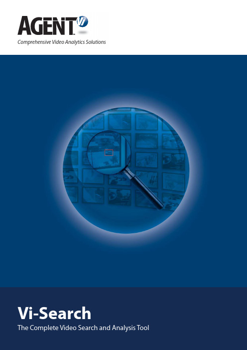
Comprehensive Video Analytics SolutionsVi-SearchThe Complete Video Search and Analysis ToolVi-Search is an innovative video search software that enables rapid and effective retrieval and presentation of specific video segments, events and data from vast amounts of recorded video. While video recording is a basic component of most surveillance networks, the recorded video is rarely utilized due to the lack of an automated and time-efficient solution that enables search and analysis of such stored video. In response, V i-Search automates the search and analysis process and allows for true leveraging of the stored video.The software analyzes the video stream, generates metadata describing the scene content, and allows for later retrieval and analysis of the video through an automatic search within the stored metadata.Based on Agent Vi’s open architecture, pure software approach, Vi-Search seamlessly integrates with a wide range of edge devices and video management systems, in both new and existing surveillance networks.Vi-Search HighlightsAutomatic and Time-Efficient• Scans days of stored video in seconds to display precise results• Eliminates the need for time-consuming manual search and review of stored videoSearch Flexibility• Enables search by event or search by target parameters, including type, size and color• Scene metadata is continuously collected and logged, with no need to pre-define search parametersHighly Scalable• Can be easily applied and expanded to surveillance networks of any size• Enables simultaneous search on multiple cameras Open Architecture• Integrated with a wide range of edge devices and video management systems• Search can be conducted through Vi-Search’s GUI or an integrated third party video management system Hardware-Efficient• Single server can generate detailed and accurate scene metadata for hundreds of cameras simultaneously User-Friendly• No complicated set-up or training required• Operated by simple search queries• Enables easy export of specific video segments and reports as stand-alone filesApplicationsVi-Search enables utilization of stored video for a wide variety of security, safety, law enforcement and business intelligence applications:Business Intelligence and Operational Efficiency applications can benefit from statistical analysis of human or vehicle traffic in specific areas and in distinct time frames. Retail chains and other businesses or organizations can better understand and predict traffic patterns to efficiently allocate resources, provide better customer care, and improve operational procedures.Forensic Analysis often requires search through vast amounts of stored video to pinpoint certain events, or to trace events back to their origin. Through its wide range of search parameters and capabilities, Vi-Search enables users to locate an event in the stored video with high precision in a matter of seconds. A stand-alone file containing the relevant video segment can be easily extracted and saved as evidence.Time-Critical Security and Law Enforcement Opera-tions require quick and effective responses to events as they occur. Once there is knowledge of a criminal or ter-rorist activity, events can be traced back for immediate investigation, providing law enforcement agencies with a full picture of the event including origin and evolution. In this way, deployment and tactical responses are better informed, improving crisis management.V i-Search allows you to reap the true benefits of your surveillance network by enabling automatic and effortless retrieval and analysis of valuable information contained in your stored video.Search and Analysis Functionality Vi-Search provides the following main search and analysis functionalities:Forensic SearchEnables search for particular events or objects in a speci-fied group of cameras and within a distinct time frameStatistical AnalysisConducts people or vehicle counting and generates statistical reports, for a specified group of cameras and within a distinct time frameMotion Path AnalysisProduces graphical presentation of all motion paths in a scene, with immediate access to the video segment relating to each pathVideo SummaryAllows debriefing of multiple search results through one condensed clipSearch Parameters and CapabilitiesVi-Search offers an extensive set of intuitive search parameters and capabilities, including: • Target Type – People, Vehicles, Objects• Event Type – Moving, Stationary, Crossing a line, Occupancy, Crowding • Search by Color and/or Size • Search within defined time frames• Search on selected cameras or group of cameras • Search for Similar Targets – Once a target is observed, a simple search can be conducted to locate additional appearances of the same or similar target in the recorded videoVi-Search is a complete video search and analysis solution. Its open architecture, hardware-efficient approach makes Vi-Search a feasible and effective solution for all markets and industries.Software & Hardware RequirementsVi-Search Server(for 100 cameras)•CPU - Core2Duo 2.66 GH (or similar), RAM - 2 GB• Hard drive - 200 GB per month of storage• OS - Windows XP Professional, Windows Server 2003, Windows Server 2008Vi-Search Client• CPU - Core2Duo 2.4G Hz (or similar), RAM - 1 GB• Hard drive - 50 GB• OS - Windows XP Professional, Windows VistaServer Scalability Analytics servers can be easily added to support more camerasStronger processors can support more cameras on one serverSystem PerformanceQuery Time Average of 15 seconds per camera per 24 hours of recorded metadataRequired Metadata Storage Average of 50 MB per camera per dayIntegration PartnersSupported Edge Devices Axis, COE, IQInVision, MangoDSP, Sony, Verint, VivotekFor additional devices and specific models contact ****************Supported VideoManagement SystemsMilestone, OnSSI, ViconFor a list of vendors and supported versions contact****************Agent Video Intelligence (Agent Vi) is a leading provider of open architecture, video analytics software deployed in a variety of security, safety and business intelligence applications worldwide. The comprehensive video analytics solutions offered by Agent Vi extend from real-time video analysis and alerts to forensic search and post-event analysis, and are fully integrated with a range of third party edge devices and video management systems. Integrating Agent Vi’s advanced video analytics capabilities into existing or new surveillance networks enables users to benefit from the true potential of their surveillance networks, transforming them into intelligent tools that respond to the practical challenges of the 21st century.Agent Video Intelligence Ltd. USA: +1 303 534 5106 EMEA & APAC: +972 72 220 1500For more information, visit: or email: *****************。
VI视觉识别系统设计简介
VI视觉识别系统设计简介V I即(V i s u a l I d e n t i t y),通译为视觉识别系统,是C I S系统最具传播力和感染力旳部分。
是将C I旳非可视内容转化为静态旳视觉识别符号,以无比丰富旳多样旳应用形式,在最为广泛旳层面上,进行最直接旳传播。
设计到位、实行科学旳视觉识别系统,是传播企业经营理念、建立企业著名度、塑造企业形象旳迅速便捷之途。
在品牌营销旳今天,没有V I设计对于一种现代企业来说,就意味着它旳形象将沉没于商海之中,让人辨别不清;就意味着它是一种缺乏灵魂旳盈利机器;就意味着它旳产品与服务毫无个性,消费者对它毫无眷恋;就意味着团体旳松散和低落旳士气。
V I设计一般包括基础部分和应用部分两大内容。
其中,基础部分一般包括:企业旳名称、标志设计、标识、原则字体、原则色、辅助图形、原则印刷字体、禁用规则等等;而应用部分则一般包括:标牌旗帜、办公用品、公关用品、环境设计、办公服装、专用车辆等等。
一种优秀旳V I设计对一种企业旳作用应在于:A、在明显地将该企业与其他企业辨别开来旳同步又确立该企业明显旳行业特性或其他重要特性,保证该企业在经济活动当中旳独立性和不可替代性;明确该企业旳市场定位,属企业旳无形资产旳一种重要构成部分;B、传达该企业旳经营理念和企业文化,以形象旳视觉形式宣传企业;C、以自己特有旳视觉符号系统吸引公众旳注意力并产生记忆,使消费者对该企业所提供旳产品或服务产生最高旳品牌忠诚度;D、提高该企业员工对企业旳认同感,提高企业士气。
V I设计旳基本原则:V I旳设计不是机械旳符号操作,而是以M I为内涵旳生动表述。
因此,V I设计应多角度、全方位地反应企业旳经营理念。
A、风格旳统一性原则B、强化视觉冲击旳原则C、强调人性化旳原则D、增强民族个性与尊重民族风俗旳原则E、可实行性原则:V I设计不是设计师旳异想天开而是规定具有较强旳可实行性。
假如在实行性上过于麻烦,或因成本昂贵而影响实行,再优秀旳V I设计也会由于难以贯彻而成为空中楼阁、纸上谈兵。
LabVIEW2012基本介绍
LabVIEW 2012 基本介绍一.LabVIEW环境基础知识LabVIEW程序又称虚拟仪器,或VI,其外观和操作模拟真实的物理仪器,例如示波器和万用表。
LabVIEW拥有一整套工具用于采集、分析、显示和存储数据,以及解决用户编写代码过程中可能出现的问题。
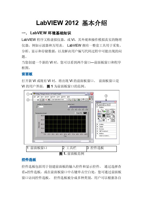
当您创建一个新的VI时,您可以看到两个窗口—前面板窗口和程序框图。
前面板打开新VI或现有VI时,将出现VI的前面板窗口。
前面板窗口是VI的用户界面。
图1为前面板窗口的范例。
控件选板控件选板包括用于创建前面板的输入控件和显示控件。
通过选择查看»控件选板,或在前面板窗口中右键单击空白处,您可通过前面板窗口访问控件选板。
控件选板被分成多种类别,用户可以根据各自需要显示部分或者全部类别。
图2显示了所有控件选板类别,并展开了新式类别。
图2.控件选板显示或隐藏类别(子选板),点击―自定义‖按钮,并选择更改可见选板。
输入控件和显示控件每个VI都包含一个前面板,您可以将它视为用户界面进行设计。
当您从别的程序框图调用VI时,您也可以使用前面板,传输输入、接收输出。
将输出控件和显示控件放置在VI前面板上,创建一个VI 的用户界面。
当您将前面板作为用户界面交互时,您可以通过修改控件提供输入,并在显示控件中查看结果。
输入控件决定输入,显示控件显示输出。
输入控件通常是旋钮、按钮、转盘、滑块和字符串。
输入控件仿真仪器的输入装置,为VI的程序框图提供数据。
显示控件通常是图形、图表、LED灯和状态字符串。
显示控件仿真仪器的输出装置,显示程序框图获取或生成的数据。
图1中有两个控件:测量次数和延迟(秒)。
有一个显示控件:XY 坐标图,称为温度图。
用户可以为测量次数和延迟(秒)控件改变输入值。
还可在温度图上看到VI生成的值。
VI基于程序框图中的代码生成显示控件值。
每个输入控件和显示控件都有与其相关的数据类型。
例如,水平滑动杆延迟(秒)是数值型数据类型。
最常用的数据类型为数值型、布尔型和字符串型。
- 1、下载文档前请自行甄别文档内容的完整性,平台不提供额外的编辑、内容补充、找答案等附加服务。
- 2、"仅部分预览"的文档,不可在线预览部分如存在完整性等问题,可反馈申请退款(可完整预览的文档不适用该条件!)。
- 3、如文档侵犯您的权益,请联系客服反馈,我们会尽快为您处理(人工客服工作时间:9:00-18:30)。
12 1-800-735-6200
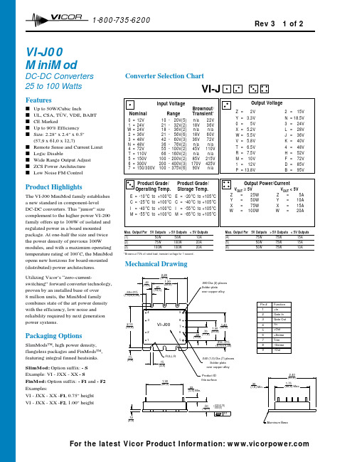
VI-J00MiniMod
DC-DC Converters 25 to 100 Watts
Product Highlights
The VI-J00 MiniMod family establishes a new standard in component-level DC-DC converters. This “junior” size complement to the higher power VI-200family offers up to 100W of isolated and regulated power in a board mounted package. At one-half the size and twice the power density of previous 100W modules, and with a maximum operating temperature rating of 100˚C, the MiniMod opens new horizons for board-mounted (distributed) power architectures. Utilizing Vicor’s “zero-current-switching” forward converter technology,proven by an installed base of over 8 million units, the MiniMod family combines state of the art power density with the efficiency, low noise and reliability required by next generation power systems.
Packaging Options
SlimMods™, high power density,flangeless packages and FinMods™,featuring integral finned heatsinks.SlimMod: Option suffix: - S Example: VI - JXX - XX - S
FinMod: Option suffix: - F1and - F2Examples:
VI - JXX - XX -F1, 0.75" height VI - JXX - XX -F2, 1.00" height
Converter Selection Chart
VI-J
Max. Output For 5V Outputs > 5V Outputs < 5V Outputs
(1)50W 50W 10A (2)75W 100W 20A (3)100W 100W 20A
Max. Output For 5V Outputs > 5V Outputs < 5V Outputs
(4)75W 75W 15A (5)50W 75W 15A (6)50W 75W 10A
Features
s Up to 50W/Cubic Inch
s UL, CSA, TÜV, VDE, BABT s CE Marked
s Up to 90% Efficiency s Size: 2.28" x 2.4" x 0.5"(57,9 x 61,0 x 12,7)
s Remote Sense and Current Limit s Logic Disable
s Wide Range Output Adjust s ZCS Power Architecture s
Low Noise FM Control
Mechanical Drawing
(7,6) Min.
(3,0)
.12.30
*Brownout 75% of rated load; transient voltage for 1 second.
Rev 3 1 of 2
For the latest Vicor Product Information:
12 1-800-735-6200
73
Converter Specifications
(typical at T BP =25°C, nominal line and 75% load, unless otherwise specified)
VI-J00 E-Grade
VI-J00 C-, I-, M-Grade
PARAMETER
MIN.TYP.MAX.
MIN.
TYP.
MAX.
UNITS
TEST CONDITIONS
s Input Characteristics Inrush charge
60x10-660x10-6100x10-6
Coulombs
Nominal line
Input reflected ripple current – pp 10%10%
I IN
Nominal line, full load Input ripple rejection
dB 120 Hz, nominal line dB
2400 Hz, nominal line
No load power dissipation 1.352
1.35
2Watts
s Output Characteristics Setpoint accuracy 1.0%
2.0%0.5% 1.0%V NOM Load/line regulation 0.5%0.05%0.2%V NOM LL to HL, 10% to Full Load Load/line regulation
1.0%0.2%0.5%V NOM LL to HL, No Load to 10%Output temperature drift 0.020.010.02
%/°C Over rated temperature
Long term drift 0.020.02%/1K hours
Output ripple - pp: 2V, 3.3V 200100150mV
20 MHz bandwidth 5V 5%2%3%20 MHz bandwidth 10-48V 3%
0.75%
1.5%20 MHz bandwidth Trim range 1
50%110%50%110%V NOM Total remote sense compensation 0.50.5Volts 0.25V max. neg. leg Current limit
105%135%105%125%I NOM Automatic restart
Short circuit current 105%
140%
105%
130%
I NOM
s Control Pin Characteristics Gate out impedance 5050Ohms Gate in impedance 103103
Ohms Gate in high threshold 6
6Volts Use open collector
Gate in low threshold 0.65
0.65
Volts Gate in low current 6
6mA
s Dielectric Withstand Characteristics Input to output 3,0003,000V RMS Baseplate earthed
Output to baseplate 500500V RMS Input to baseplate 1,5001,500
V RMS
s Thermal Characteristics Efficiency
78-88%80-90%Baseplate to sink 0.40.4
°C/Watt With Vicor P/N 04308
s Mechanical Specifications Weight
3.0 (85) 3.0 (85)Ounces (Grams)
110V, 12V and 15V outputs, standard trim range ±10%. Consult factory for wider trim range.
For product compliance with agency standards please refer to pages 67 - 69.
25+20Log
( Vin Vout
30+20Log ( Vin
Vout
20+20Log ( Vin
)
Rev 3 2 of 2
For the latest Vicor Product Information: 。