L298N芯片手册
L298N中文资料

L298N中文资料步进电机驱动芯片L298中文资料双全桥步进电机专用驱动芯片( Dual Full-Bridge Driver )L298中文资料L298N 为SGS-THOMSON Microelectronics 所出产的双全桥步进电机专用驱动芯片( Dual Full-Bridge Driver ) ,内部包含4信道逻辑驱动电路,是一种二相和四相步进电机的专用驱动器,可同时驱动2个二相或1个四相步进电机,内含二个H-Bridge 的高电压、大电流双全桥式驱动器,接收标准TTL逻辑准位信号,可驱动46V、2A以下的步进电机,且可以直接透过电源来调节输出电压;此芯片可直接由单片机的IO端口来提供模拟时序信号,但在本驱动电路中用L297 来提供时序信号,节省了单片机IO 端口的使用。
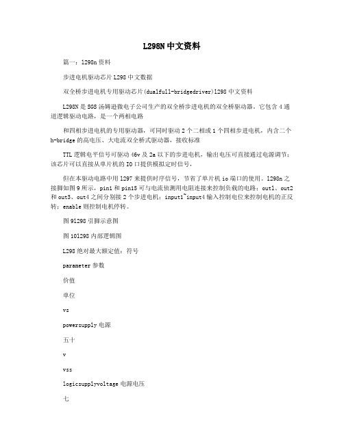
L298N 之接脚如图9 所示,Pin1 和Pin15 可与电流侦测用电阻连接来控制负载的电路; OUTl、OUT2 和OUT3、OUT4 之间分别接2 个步进电机;input1~input4 输入控制电位来控制电机的正反转;Enable 则控制电机停转。
图9 L298引脚图图10 L298 内部逻辑图L298 ABSOLUTE MAXIMUM RATINGS 绝对最大额定值: Symbol符号Parameter 参数Value数值单位VSPower Supply 电源50VSSLogic Supply Voltage 电源电压7VVI,VenInput and Enable Voltage 输入电压和启用–0.3 to 7VIO峰值输出电流(每通道)非重复性(t= 100ms)3重复(80% on –20% off; ton = 10ms) 2.5直流运行2VsensSensing Voltage 感应电压–1 to 2.3VPtotTotal Power Dissipation (Tcase=75℃)总功率耗散(Tcase=75 ℃)25WTopJunction Operating Temperature 结工作温度–25 to 130℃Tstg,TjStorage and Junction Temperature 储存温度–40 to 150℃L298 PIN FUNCTIONS (refer to the block diagram) 引脚功能(请参阅框图):PowerSONameFunction 功能说明1;152;19Sense A; Sense B 引脚电流监测端,1、15和PowerSO的2、19用法一样,SEN1、SEN2分别为两个H桥的电流反馈脚,不用时可以直接接地2;34;5Out 1; Out 21Y1、1Y2输出端46VS功率电源电压,此引脚与地必须连接100nF电容器 5;77;9Input 1; Input 21A1、1A2输入端,TTL电平兼容6;118;14Enable A; Enable BTTL电平兼容输入 1EN、2EN使能端,低电平禁止输出 81,10,11,20GNDGND地912VSS逻辑电源电压。
L298N中文资料
L298N中文资料步进电机驱动芯片L298中文资料双全桥步进电机专用驱动芯片( Dual Full-Bridge Driver )L298中文资料L298N 为SGS-THOMSON Microelectronics 所出产的双全桥步进电机专用驱动芯片( Dual Full-Bridge Driver ) ,内部包含4信道逻辑驱动电路,是一种二相和四相步进电机的专用驱动器,可同时驱动2个二相或1个四相步进电机,内含二个H-Bridge 的高电压、大电流双全桥式驱动器,接收标准TTL逻辑准位信号,可驱动46V、2A以下的步进电机,且可以直接透过电源来调节输出电压;此芯片可直接由单片机的IO端口来提供模拟时序信号,但在本驱动电路中用L297 来提供时序信号,节省了单片机IO 端口的使用。
L298N 之接脚如图9 所示,Pin1 和Pin15 可与电流侦测用电阻连接来控制负载的电路; OUTl、OUT2 和OUT3、OUT4 之间分别接2 个步进电机;input1~input4 输入控制电位来控制电机的正反转;Enable 则控制电机停转。
图9 L298引脚图图10 L298 内部逻辑图L298 ABSOLUTE MAXIMUM RATINGS 绝对最大额定值: Symbol符号Parameter 参数Value数值单位VSPower Supply 电源50VSSLogic Supply Voltage 电源电压7VVI,VenInput and Enable Voltage 输入电压和启用–0.3 to 7VIO峰值输出电流(每通道)非重复性(t= 100ms)3重复(80% on –20% off; ton = 10ms) 2.5直流运行2VsensSensing Voltage 感应电压–1 to 2.3VPtotTotal Power Dissipation (Tcase=75℃)总功率耗散(Tcase=75 ℃)25WTopJunction Operating Temperature 结工作温度–25 to 130℃Tstg,TjStorage and Junction Temperature 储存温度–40 to 150℃L298 PIN FUNCTIONS (refer to the block diagram) 引脚功能(请参阅框图):PowerSONameFunction 功能说明1;152;19Sense A; Sense B 引脚电流监测端,1、15和PowerSO的2、19用法一样,SEN1、SEN2分别为两个H桥的电流反馈脚,不用时可以直接接地2;34;5Out 1; Out 21Y1、1Y2输出端46VS功率电源电压,此引脚与地必须连接100nF电容器 5;77;9Input 1; Input 21A1、1A2输入端,TTL电平兼容6;118;14Enable A; Enable BTTL电平兼容输入 1EN、2EN使能端,低电平禁止输出 81,10,11,20GNDGND地912VSS逻辑电源电压。
【2018-2019】l298n中文资料-实用word文档 (9页)

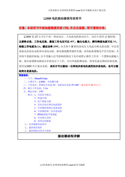
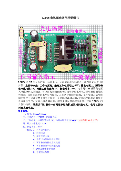
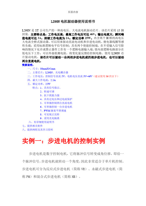
本文部分内容来自网络整理,本司不为其真实性负责,如有异议或侵权请及时联系,本司将立即删除!== 本文为word格式,下载后可方便编辑和修改! ==l298n中文资料篇一:L298N中文资料L298N电机驱动器使用说明书L298N是ST公司生产的一种高电压、大电流电机驱动芯片。
该芯片采用15脚封装。
主要特点是:工作电压高,最高工作电压可达46V;输出电流大,瞬间峰值电流可达3A,持续工作电流为2A;额定功率25W。
内含两个H桥的高电压大电流全桥式驱动器,可以用来驱动直流电动机和步进电动机、继电器线圈等感性负载;采用标准逻辑电平信号控制;具有两个使能控制端,在不受输入信号影响的情况下允许或禁止器件工作有一个逻辑电源输入端,使内部逻辑电路部分在低电压下工作;可以外接检测电阻,将变化量反馈给控制电路。
使用L298N芯片驱动电机,该芯片可以驱动一台两相步进电机或四相步进电机,也可以驱动两台直流电机。
简要说明:一、尺寸:80mmX45mm二、主要芯片:L298N、光电耦合器三、工作电压:控制信号直流5V;电机电压直流3V~46V(建议使用36伏以下)四、最大工作电流:2.5A 五、额定功率:25W特点:1、具有信号指示。
2、转速可调3、抗干扰能力强4、具有过电压和过电流保护5、可单独控制两台直流电机6、可单独控制一台步进电机7、PWM脉宽平滑调速8、可实现正反转9、采用光电隔离六、有详细使用说明书七、提供相关软件八、提供例程及其学习资料实例一:步进电机的控制实例步进电机是数字控制电机,它将脉冲信号转变成角位移,即给一个脉冲信号,步进电机就转动一个角度,因此非常适合于单片机控制。
步进电机可分为反应式步进电机(简称VR)、永磁式步进电机(简称PM)和混合式步进电机(简称HB)。
一、步进电机最大特点是:1、它是通过输入脉冲信号来进行控制的。
2、电机的总转动角度由输入脉冲数决定。
3、电机的转速由脉冲信号频率决定。
二、步进电机的驱动电路根据控制信号工作,控制信号由单片机产生。
L298N中文资料
L298N中文资料篇一:l298n资料步进电机驱动芯片L298中文数据双全桥步进电机专用驱动芯片(dualfull-bridgedriver)l298中文资料L298N是SGS汤姆逊微电子公司生产的双全桥步进电机的双全桥驱动器。
它包含4通道逻辑驱动电路,是一个两相电路和四相步进电机的专用驱动器,可同时驱动2个二相或1个四相步进电机,内含二个h-bridge的高电压、大电流双全桥式驱动器,接收标准TTL逻辑电平信号可驱动46v及2a以下的步进电机,输出电压可直接通过电源调节;该芯片可以直接从单片机的IO口提供模拟定时信号,但在本驱动电路中用l297来提供时序信号,节省了单片机io端口的使用。
l298n之接脚如图9所示,pin1和pin15可与电流侦测用电阻连接来控制负载的电路;outl、out2和out3、out4之间分别接2个步进电机;input1~input4输入控制电位来控制电机的正反转;enable则控制电机停转。
图9l298引脚示意图图10l298内部逻辑图L298绝对最大额定值:符号parameter参数价值单位vspowersupply电源五十vvsslogicsupplyvoltage电源电压七维恩inputandenablevoltage输入电压和启用 c0。
3到7v木卫一峰值输出电流(每通道)A.非重复性(t=100ms)三重复(80%onc20%off;ton=10ms)二点五直流运行二vsens感应电压c1to2.3五、ptot总功耗(tcase=75℃)25Wtop结工作温度c25to130tstg,tj存储和结温c40to150℃l298pinfunctions(refertotheblockdiagram)引脚功能(请参阅框图):powersoname功能描述1;152.十九sensea;senseb引脚电流监测终端1和15的使用与powerso 2和19相同。
SEN1和sen2分别是两个h桥的电流反馈引脚,不使用时可直接接地2;34.五out1;out21y1,1Y2输出4六vs电源电压、该引脚和接地必须与100nF电容器连接5;77.九input1;input21A1和1A2输入,TTL电平兼容6;118.十四enablea;enablebTTL电平与输入1EN和2EN使能端子兼容,低电平禁止输出 81,10,11,20gnd接地9十二vss逻辑电源电压。
L298N电机驱动模块详解
L298N电机驱动器使用说明书注意:本说明书中添加超链接的按CTRL并点击连接,即可看到内容。
1.信号电源引入端2.控制信号输入端3.直流电机调速PWM脉宽信号输入端。
(控制步进电机或者控制直流电机无需调速时,保持此状态)4.控制信号指示灯5.光电隔离(抗干扰) 6.核心芯片(L298N)7.二极管桥式续流保护8.电源滤波9.端子接线实例一:步进电机的控制实例步进电机是数字控制电机,它将脉冲信号转变成角位移,即给一个脉冲信号,步进电机就转动一个角度,因此非常适合于单片机控制。
步进电机可分为反应式步进电机(简称VR)、永磁式步进电机(简称PM)和混合式步进电机(简称HB)。
一、步进电机最大特点是:1、它是通过输入脉冲信号来进行控制的。
2、电机的总转动角度由输入脉冲数决定。
3、电机的转速由脉冲信号频率决定。
二、步进电机的驱动电路根据控制信号工作,控制信号由单片机产生。
(或者其他信号源)三、基本原理作用如下:两相四拍工作模式时序图:(1)控制换相顺序1、通电换相这一过程称为脉冲分配。
例如:1、两相四线步进电机的四拍工作方式,其各相通电顺序为(A-B-A’-B’)通电控制脉冲必须严格按照这一顺序分别控制A,B相的通断。
)2、两相四线步进电机的四拍工作方式,其各相通电顺序为:(A-AB-B-BA’-A’-A’B’-B’-B’依次循环。
(出于对力矩、平稳、噪音及减少角度等方面考虑。
往往采用八拍工作方式)(2)控制步进电机的转向如果给定工作方式正序换相通电,步进电机正转,如果按反序通电换相,则电机就反转。
如:正转通电顺序是:(A-B-A’-B’依次循环。
)则反转的通电顺序是:(B‘-A’-B-A依次循环。
)参考下例:(3)控制步进电机的速度如果给步进电机发一个控制脉冲,它就转一步,再发一个脉冲,它会再转一步。
两个脉冲的间隔越短,步进电机就转得越快。
调整单片机发出的脉冲频率,就可以对步进电机进行调速。
(注意:如果脉冲频率的速度大于了电机的反应速度,那么步进电机将会出现失步现象)。
L298N双H桥直流电机驱动芯片

L298N双H桥直流电
机驱动芯片
------------------------------------------作者xxxx
------------------------------------------日期xxxx
系统原理图如下:
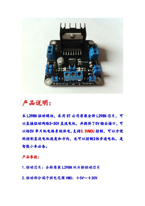
产品参数:
1.驱动芯片:L298N双H桥直流电机驱动芯片
2.驱动部分端子供电范围Vs:+5V~+35V ;如需要板内取电,则供电范围Vs:+7V~+35V
3.驱动部分峰值电流Io:2A(驱动电机的电流)
4.逻辑部分端子供电范围Vss:+5V~+7V(可板内取电+5V)
5.逻辑部分工作电流范围:0~36mA
6.控制信号输入电压范围:
低电平:-0.3V≤Vin≤1.5V
高电平:2.3V≤Vin≤Vss
7.使能信号输入电压范围:
低电平:-0.3≤Vin≤1.5V(控制信号无效)
高电平:2.3V≤Vin≤Vss(控制信号有效)
8.最大功耗:20W(温度T=75℃时)
9.存储温度:-25℃~+130℃
10.驱动板尺寸:55mm*49mm*33mm(带固定铜柱和散热片高度)
11.驱动板重量:33g
12.其他扩展:控制方向指示灯、逻辑部分板内取电接口。
不提供技术支持购买前请注意。
L298N步进电机驱动器使用说明

L298N步进电机驱动器使用说明L298N步进电机驱动器是一款广泛应用于步进电机控制的驱动器模块。
它采用双向电机驱动桥芯片L298N,可以提供高电流和高电压的驱动能力,适用于同步马达和双向直流电动机的控制。
以下是L298N步进电机驱动器的使用说明。
一、硬件连接1. 将L298N模块与Arduino主控板连接。
将L298N模块的5V和GND引脚分别连接到Arduino的5V和GND引脚。
2.将步进电机的4根线分别连接到L298N模块的输出端子A、A-、B和B-。
相应的线连接方式为:步进电机的A相线连接到L298N模块的A端子,A-相线连接到A-端子,B相线连接到B端子,B-相线连接到B-端子。
二、编码下面是一个简单的Arduino代码示例,用于控制步进电机的运动。
代码将使步进电机按指定的方向和速度旋转。
```cpp#include <Stepper.h>//设定步进电机的步数和引脚const int stepsPerRevolution = 200;Stepper myStepper(stepsPerRevolution, 8, 9, 10, 11);void setu//设置步进电机的速度myStepper.setSpeed(60);void loo//顺时针旋转一圈myStepper.step(stepsPerRevolution);delay(1000);//逆时针旋转一圈myStepper.step(-stepsPerRevolution);delay(1000);```三、常见问题解答1.如何改变步进电机的转向?需要根据具体的控制电路和驱动器设计,通过修改引脚的输出顺序或改变控制信号的频率来改变步进电机的转向。
2.怎样确定步进电机的旋转速度?可以使用`myStepper.setSpeed(speed)`函数设置步进电机的转速,其中speed的单位是步/分钟。
具体的速度可以通过试验和调节来确定。
L298N(L297+L298N)电机驱动器使用说明

用 PWM 信号对
1、具有信号指示 2、转速可调 3、抗干扰能力强 4、具有续流保护 5、可单独控制两台直流电机 6、可单独控制一台步进电机 7、PWM 脉宽平滑调速(可使 直流电机调速) 8、可实现正反转 9、采用光电隔离
控制步进电机:
实例一:步进电机的控制实例
步进电机是数字控制电机,它将脉冲信号转变成角位移,即给一 个脉冲信号,步进电机就转动一个角度,因此非常适合于单片机控制。 步进电机可分为反应式步进电机(简称 VR)、永磁式步进电机(简 称 PM)和混合式步进电机(简称 HB)。 一、步进电机最大特点是: 1、它是通过输入脉冲信号来进行控制的。 2、电机的总转动角度由输入脉冲数决定。 3、电机的转速由脉冲信号频率决定。 二、步进电机的驱动电路 根据控制信号工作,控制信号(ENA ENB)由单片机产生。(或者其他 信号源) 三、控制步进电机的速度 如果给步进电机发一个控制脉冲,它就转一步,再发一个脉冲,它会 再转一步。两个脉冲的间隔越短,步进电机就转得越快。调整单片机
将短接帽短接)实现电机正反转就更容易了,输入信号端 IN1 接高电
平输入端 IN2 接低电平,电机 M1 正转。(如果信号端 IN1 接低电平,
IN2 接高电平,电机 M1 反转。)控制另一台电机是同样的方式,输入
信号端 IN3 接高电平,输入端 IN4 接低电平,电机 M2 正转。(反之
则反转),PWM 信号端 A 控制 M1 调速,PWM 信号端 B 控制 M2 调
QQ:1035573910.
采用 15 脚封装。主要特点是:工作电压高,最高工作电压可达 46V;
输出电流大,瞬间峰值电流可达 3A,持续工作电流为 2A;最大功率 25W。内含两个 H 桥的高电压大电流全桥式驱动器,可以用来驱动直 流电动机和步进电动机、继电器线圈等感性负载;采用标准逻辑电平 信号控制;具有两个使能控制端,在不受输入信号影响的情况下允许 或禁止器件工作有一个逻辑电源输入端,使内部逻辑电路部分在低电 压下工作;可以外接检测电阻,将变化量反馈给控制电路。使用 L298N 芯片驱动电机,该芯片可以驱动一台两相步进电机或四相步进电机, 也可以驱动两台直流电机,是智能小车必备。
L298N电机驱动使用说明
对于直流电机调速,我们也可以运用使能端,把 PWM 波通入使能端, 根据占空比的不同,我们可以得到不同的速度(具体参考我们所给的 51 程序) 注意事项: 1.如果接入的电压超过 16V ,,自己给模块 VCC5 端通入 5V 电压, 并且把 5V 使能跳帽拿下。 2.打开开关前检查正负极有无接错,如果接错电源指示灯是不会亮 的。 3.驱动板上有个 VCC 字样的插口,我们已经用跳帽封住,这个接口 是提供电源电压的,并不是提供 5V 输出的,请勿接错。
立
z++;
if(z==4)z=0;
}
break;
case 2:
angle = angle*5/9; //每转一下 1.8 度
for(i=0;i<angle;i++){
P1 = STEP_TABLE2[k];
for(y=speed;y>0;y--); //延时一点时间,让电机内的磁场能够
建立
k++;
if(k==4)k=0;
}
break;
default: break;
}
}
void main(void) {
while(1){ turnangle(180000,2,205); delay(5000); turnangle(72000,2,300); delay(5000); turnangle(252000,1,205); delay(5000);
}
void time0_int() interrupt 1 using 1 {
TR0=0; TH0=0xF4; TL0=0x48; MA++; if(MA< SpeedA){
ENA = 1; } else ENA = 0; if(MA == 40){
L298N中文资料
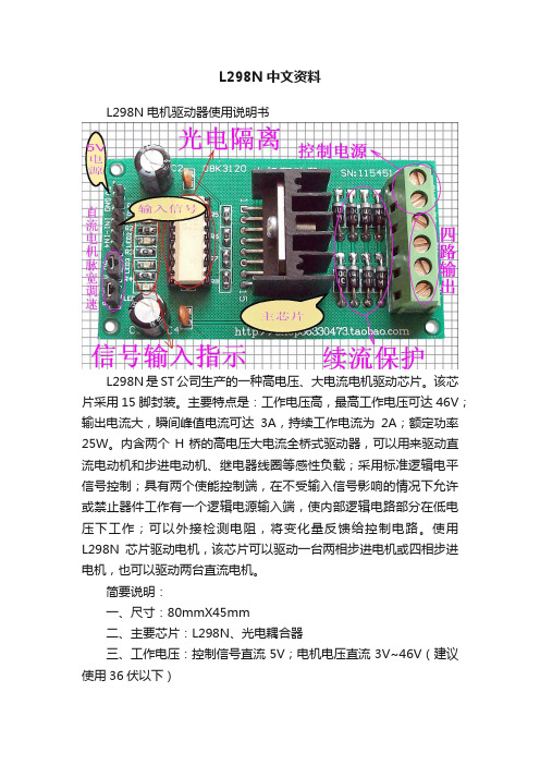
L298N中文资料L298N电机驱动器使用说明书L298N是ST公司生产的一种高电压、大电流电机驱动芯片。
该芯片采用15脚封装。
主要特点是:工作电压高,最高工作电压可达46V;输出电流大,瞬间峰值电流可达3A,持续工作电流为2A;额定功率25W。
内含两个H桥的高电压大电流全桥式驱动器,可以用来驱动直流电动机和步进电动机、继电器线圈等感性负载;采用标准逻辑电平信号控制;具有两个使能控制端,在不受输入信号影响的情况下允许或禁止器件工作有一个逻辑电源输入端,使内部逻辑电路部分在低电压下工作;可以外接检测电阻,将变化量反馈给控制电路。
使用L298N芯片驱动电机,该芯片可以驱动一台两相步进电机或四相步进电机,也可以驱动两台直流电机。
简要说明:一、尺寸:80mmX45mm二、主要芯片:L298N、光电耦合器三、工作电压:控制信号直流5V;电机电压直流3V~46V(建议使用36伏以下)四、最大工作电流:2.5A五、额定功率:25W特点:1、具有信号指示。
2、转速可调3、抗干扰能力强4、具有过电压和过电流保护5、可单独控制两台直流电机6、可单独控制一台步进电机7、PWM脉宽平滑调速8、可实现正反转9、采用光电隔离六、有详细使用说明书七、提供相关软件八、提供例程及其学习资料实例一:步进电机的控制实例步进电机是数字控制电机,它将脉冲信号转变成角位移,即给一个脉冲信号,步进电机就转动一个角度,因此非常适合于单片机控制。
步进电机可分为反应式步进电机(简称VR)、永磁式步进电机(简称PM)和混合式步进电机(简称HB)。
一、步进电机最大特点是:1、它是通过输入脉冲信号来进行控制的。
2、电机的总转动角度由输入脉冲数决定。
3、电机的转速由脉冲信号频率决定。
二、步进电机的驱动电路根据控制信号工作,控制信号由单片机产生。
(或者其他信号源)如图:按CTRL并点击(L298N驱动器与直流电机接线图)三、基本原理作用如下:两相四拍工作模式时序图:步进电机信号输入第一步第二步第三步第四步返回第一步正转IN1 0 1 1 1 返回IN2 1 0 1 1 返回IN3 1 1 0 1 返回IN4 1 1 1 0 返回反转IN1 1 1 1 0 返回IN2 1 1 0 1 返回IN3 1 0 1 1 返回IN4 0 1 1 1 返回(1)控制换相顺序1、通电换相这一过程称为脉冲分配。
L298N电机驱动板用户手册说明书
User ManualForL298N Motor Driver Board (ST1112)1. IntroductionDouble H driver module uses ST L298N dual full-bridge driver, an integrated monolithic circuit in a 15- lead Multiwatt and PowerSO20 packages. It is a high voltage, high current dual full-bridge driver designed to accept standard TTL logic levels and drive inductive loads such as relays, solenoids, DC and stepping motors. Two enable inputs are provided to enable or disable the device independently of the input signals. The emitters of the lower transistors of each bridge are connected together and the corresponding external terminal can be used for the con-nection of an external sensing resistor. An additional supply input is provided so that the logic works at a lower voltage.Specification:∙Driver: L298N∙Driver power supply: +5V/DC to +35V/DC∙Driver Io: 2A∙Logic power output Vss: +5/DC to 7V/DC (internal supply +5V/DC)∙Logic current: 0 - 36mA∙Controlling level: Low -0.3V/DC to 1.5V/DC, high: 2.3V/DC to Vss∙Enable signal level: Low -0.3V/DC to 1.5V/DC, high: 2.3V/DC - Vss∙Max power: 25W (Temperature 75 cesus)∙Working temperature: -25℃to +130℃2. Pin Instruction3. ExampleThis module can drive 2 channel DC motor or 2 phase stepper motor. For 2 channel DC motor, connection and code as below: Connection:IN1==========13;IN2==========12;IN3==========11;IN4==========10;********Code begin********int in1=13;int in2=12;int in3=11;int in4=10;int speedPinA=6;int speedPinB=5;void setup(){pinMode(in1,OUTPUT);pinMode(in2,OUTPUT);pinMode(in3,OUTPUT);pinMode(in4,OUTPUT);digitalWrite(in1,HIGH);digitalWrite(in2,HIGH);digitalWrite(in3,HIGH);digitalWrite(in4,HIGH);}void loop(){_mRight(in1,in2);_mRight(in3,in4);int n=analogRead(A0)/4;_mSetSpeed(speedPinA,n);_mSetSpeed(speedPinB,n);}void _mRight(int pin1,int pin2){digitalWrite(pin1,HIGH);digitalWrite(pin2,LOW);}void _mLeft(int pin1,int pin2){digitalWrite(pin1,LOW);digitalWrite(pin2,HIGH);}void _mStop(int pin1,int pin2){digitalWrite(pin1,HIGH);digitalWrite(pin2,HIGH);}void _mSetSpeed(int pinPWM,int SpeedValue{analogWrite(pinPWM,SpeedValue);}********Code End********For 2 stepper motor the connection and code as below: Connection:IN1=======8;IN2=======9;IN3=======10;IN4=======11;******Code begin******#include <Stepper.h>#define STEPS 100Stepper stepper(STEPS, 8, 9, 10, 11);int previous = 0;void setup(){stepper.setSpeed(90);}void loop(){int val = analogRead(0); stepper.step(val - previous);previous = val;}******Code End******。
L298中文资料PWM调速
L298N电机驱动器使用说明书L298N是ST公司生产的一种高电压、大电流电机驱动芯片。
该芯片采用15脚封装。
主要特点是:工作电压高,最高工作电压可达46V;输出电流大,瞬间峰值电流可达3A,持续工作电流为2A;额定功率25W。
内含两个H桥的高电压大电流全桥式驱动器,可以用来驱动直流电动机和步进电动机、继电器线圈等感性负载;采用标准逻辑电平信号控制;具有两个使能控制端,在不受输入信号影响的情况下允许或禁止器件工作有一个逻辑电源输入端,使内部逻辑电路部分在低电压下工作;可以外接检测电阻,将变化量反馈给控制电路。
使用L298N芯片驱动电机,该芯片可以驱动一台两相步进电机或四相步进电机,也可以驱动两台直流电机。
简要说明:一、尺寸:80mmX45mm二、主要芯片:L298N、光电耦合器三、工作电压:控制信号直流5V;电机电压直流3V~46V(建议使用36伏以下)四、最大工作电流:2.5A五、额定功率:25W特点:1、具有信号指示。
2、转速可调3、抗干扰能力强4、具有过电压和过电流保护5、可单独控制两台直流电机6、可单独控制一台步进电机7、PWM脉宽平滑调速8、可实现正反转9、采用光电隔离六、有详细使用说明书七、提供相关软件八、提供例程及其学习资料实例一:步进电机的控制实例步进电机是数字控制电机,它将脉冲信号转变成角位移,即给一个脉冲信号,步进电机就转动一个角度,因此非常适合于单片机控制。
步进电机可分为反应式步进电机(简称VR)、永磁式步进电机(简称PM)和混合式步进电机(简称HB)。
一、步进电机最大特点是:1、它是通过输入脉冲信号来进行控制的。
2、电机的总转动角度由输入脉冲数决定。
3、电机的转速由脉冲信号频率决定。
二、步进电机的驱动电路根据控制信号工作,控制信号由单片机产生。
(或者其他信号源) 三、基本原理作用如下:两相四拍工作模式时序图:(1)控制换相顺序1、通电换相这一过程称为脉冲分配。
例如:1、两相四线步进电机的四拍工作方式,其各相通电顺序为(A-B-A’-B’)依次循环。
l298n中文资料_数据手册_参数

L298N中文资料第7页精选内容:图7:对于较高的电流,输出可以并联.注意平行通道1与通 道4和通道2与通道3.应用信息(参考框图) 1.1.电源输出阶段 L298集成了两个动力输出阶段 (A??; B).功率输出级是桥式配置其输出可以驱动一个电感负载,周期性或差异性模式,取 决于状态输入.流过负载的电流在这个意义上,从桥上出来:an 外部电阻(R SA ; R SB .)允 许检测内部 电阻这种电流的张力. 1.2.输入阶段每座桥都由四个门驱动,放入其中In1; In2; EnA和In3; In4; ENB. In输入设置桥接状态高 ; En输入的低状态抑制了桥接.所有的输入都是 TTL兼容的. 2.建议一个非感应电容器,通常为100nF,必须在Vs和Vss之间预见到地面,尽可 能靠近GND引脚.当大的ca-电源的供应商离IC太远了第二小的一个必须预见在附近 L298.感 应电阻器,不是线绕式的,必须的必须在VL298Ns的负极附近接地靠近IC的GND引脚每个 输入必须连接到的源通过非常短的路径驱动信号.打开和关闭:在打开Sup-在关闭电源之 前,Enablein-必须把它驱动到Low状态. 3.应用程序图6显示了一个双向直流电机控制Schematic只需要一个桥的图.二极管D1到D4的外部电桥是由四个快速恢复元素(trr ≤200纳秒) 必须选择尽可能低的VF负载电流的最坏情况.感测输出电压可以用来控制通过斩波输入来实 现电流幅度,通过切换低电L298N平来实现过流保护,能够输入.制动功能(快速电机停 止)要求 2安培的绝对最大额定值必须永远不会被克服.当重复峰值电流需要从负载高于2安 培,并联配置 - 可以选择(见图7).需要在外部连接二极管时,受到负载的驱动和输入的时 候 IC切碎;肖特基二极管L298N将是优选的. L298 7/13图1电路的建议印刷电路板布局 8(1:1 比例).图10:使用电流控制器L6506的双相双极步进电机控制电路 R R 和R sense 取决于负载 电流 L298 9/13灌电流延迟时间与输入0 V启用切换的关系.图6:双向DC电机控制. L =低 H = 高 X =不在乎在pu ts功能 V en = H C = H; D = L前锋 C = L; D = H相反 C = D快速电机停止 引 脚连接(顶视图) GND输入2 VSS NC出1 V S出2输入1启用A感觉A GND 10 8 9 7 6五 4 3 2 13 14 15 16 17 19 18 20 12 1 11 GND D95IN239输入3启用B出3输入4出4 NC感觉B GND绝对最大额 定值塞尔参数值联合国 V S电源 5L298N0 V V SS逻辑电源电压 7 V V I ,V en输入和使能电压 -0.3至7 V 我 哦峰值输出电流(每个通道) - 非重复(t = 100微秒) -Repetitive(80%在-20% off; t on = 10ms) -DC操作 3 2.5 2一个一个一个 V 感觉感应电压 -1?2.3 V P tot 总功耗(T case = 75 C) 25 w ^ T op结工作温度 -25至130 C T stg ,T j存储和结温 -40至150 C热数据塞尔参数 Po werSO20 Mu ltww 15联合国 第j个案例热阻结套最大. - 3 °C / W R th j-amb热阻结环境最大. 13(*) 35 °C / W (*)安装在铝基板上 1 2 3 4五 6 7 9 10 11 8启用B INPUT 3 逻辑电源电压V SS GND输入2启用A输入1 电源电压输出2输出1电流传感器A TAB连接到针脚8 13 14 15 12电 流传感器B输出4输出3输入4 D95IN240A Multiwatt15 PowerSO20 L298 2/13.工作电源电压高达 46 V .总直流电流高达4 A .低饱和电压 .过度保护 .逻辑“0”输入电压高达1.5 V (高噪声免 疫)描述 L298是一款集成的单片电路,引领Multiwatt和PowerSO20封装.它是一个高电压,大 电流双桥全驱动器,签署接受标准的L298NTTL逻辑电平和驱动感性负载,如继电器,螺线 管,直流和步进电机提供两个启用输入启用或禁用设备,放信号.下部晶体管的发射极每个 桥连接在一L298N起,外部终端可以用于会议一个外部电阻器.额外的提供供应输入,使得 逻辑在a处工作电压较低. L298N图中电路的建议印刷电路板布局图. 8(1:1比例).图10:使 用电流控制器L6506的双相双极步进电机控制L298N电路. R R 和R R 取决于负载电流 L298N
L298N资料

L298 n 全部资料免费放送L298N 为SGS-THOMSON Microelectronics 所出产的双全桥步进电机专用驱动芯片( Dual Full-Bridge Driver ) ,内部包含4信道逻辑驱动电路,是一种二相和四相步进电机的专用驱动器,可同时驱动2个二相或1个四相步进电机,内含二个H-Bridge 的高电压、大电流双全桥式驱动器,接收标准 TTL逻辑准位信号,可驱动46V、2A以下的步进电机,且可以直接透过电源来调节输出电压;此芯片可直接由单片机的IO端口来提供模拟时序信号,但在本驱动电路中用L297 来提供时序信号,节省了单片机IO 端口的使用。
L298N 之接脚如图9 所示,Pin1 和Pin15 可与电流侦测用电阻连接来控制负载的电路;OUTl、OUT2 和OUT3、OUT4 之间分别接2 个步进电机;input1~input4 输入控制电位来控制电机的正反转;Enable 则控制电机停转。
L298 ELECTRICAL CHARACTERISTICS(VS=42V;VSS=5V,Tj=25℃; unless otherwiseIiH High Voltage Input Current 高电平输入电流(引脚5,7,10,12)Vi = H ≤VSS –0.6V 30 100μAVen = L Enable Low Voltage 使能端高电平电压(引脚6,11)–0.3 1.5 VVen = H Enable High Voltage 使能端低电平电压(引脚6,11)2.3 VSS VIen = L Low Voltage Enable Current(pins 6, 11) 低电平启动电流Ven = L –10μAIen = H High Voltage Enable Current(pins 6, 11) 高电平启动电流Ven =H ≤VSS –0.6V 30 100μAVCEsat(H) Source Saturation Voltage IL =1A 0.95 1.35 1.7V IL =2A 2 2.7VCEsat(L) Sink Saturation Voltage IL = 1A (5) 0.85 1.2 1.6V IL = 2A (5) 1.7 2.3VCEsat Total Drop IL = 1A (5) 1.80 3.2V IL = 2A (5) 4.9Vsens Sensing Voltage电流监测电压(引脚1,15)–1(1) 2 V图11 L298 外形图。
L298N中文资料
L298N电机驱动器使用说明书L298N是ST公司生产的一种高电压、大电流电机驱动芯片。
该芯片采用15脚封装。
主要特点是:工作电压高,最高工作电压可达46V;输出电流大,瞬间峰值电流可达3A,持续工作电流为2A;额定功率25W。
内含两个H桥的高电压大电流全桥式驱动器,可以用来驱动直流电动机和步进电动机、继电器线圈等感性负载;采用标准逻辑电平信号控制;具有两个使能控制端,在不受输入信号影响的情况下允许或禁止器件工作有一个逻辑电源输入端,使内部逻辑电路部分在低电压下工作;可以外接检测电阻,将变化量反馈给控制电路。
使用L298N芯片驱动电机,该芯片可以驱动一台两相步进电机或四相步进电机,也可以驱动两台直流电机。
简要说明:一、尺寸:80mmX45mm二、主要芯片:L298N、光电耦合器三、工作电压:控制信号直流5V;电机电压直流3V~46V(建议使用36伏以下)四、最大工作电流:2.5A五、额定功率:25W特点:1、具有信号指示。
2、转速可调3、抗干扰能力强4、具有过电压和过电流保护5、可单独控制两台直流电机6、可单独控制一台步进电机7、PWM脉宽平滑调速8、可实现正反转9、采用光电隔离六、有详细使用说明书七、提供相关软件八、提供例程及其学习资料实例一:步进电机的控制实例步进电机是数字控制电机,它将脉冲信号转变成角位移,即给一个脉冲信号,步进电机就转动一个角度,因此非常适合于单片机控制。
步进电机可分为反应式步进电机(简称VR)、永磁式步进电机(简称PM)和混合式步进电机(简称HB)。
一、步进电机最大特点是:1、它是通过输入脉冲信号来进行控制的。
2、电机的总转动角度由输入脉冲数决定。
3、电机的转速由脉冲信号频率决定。
二、步进电机的驱动电路根据控制信号工作,控制信号由单片机产生。
(或者其他信号源)三、基本原理作用如下:两相四拍工作模式时序图:(1)控制换相顺序1、通电换相这一过程称为脉冲分配。
例如:1、两相四线步进电机的四拍工作方式,其各相通电顺序为(A-B-A’-B’)通电控制脉冲必须严格按照这一顺序分别控制A,B相的通断。
L298N模块使用说明书
3.驱动部分峰值电流 Io:2A 4.逻辑部分端子供电范围 Vss:3.3-5.5V 5.逻辑部分工作电流范围:0~47mA 6.控制信号输入电压范围:高电平4.5-5.5V 低电平0V 7.最大功耗:20W 8.存储温度:-25℃~+130℃ 9.驱动板尺寸:55mm*49mm*33mm 10.驱动板重量:46g 11.其他功能:控制方向指示灯、电源指示,电流检测,逻 辑部分板内取电接口。
高低电平; OUT1-OUT4:OUT1、OUT2 接电机 1,OUT3、OUT4 接电机 2,OUT1 和 OUT2 有电压差即一个为高一个为低电机才转; ENA:OUT1-OUT2 的使能端,高电平有效,低电平禁止,跳线 帽接上默认 ENA 为高电平,一般不用管,如果需要 PWM 调速, 就需要拔掉跳线帽,ENA 接单片机 IO 口; ENB:OUT3-OUT4 的使能端,高电平有效,跳线帽接上默认 ENA 为高电平,一般不用管,如果需要 PWM 调速,就需要拔 掉跳线帽,ENB 接单片机 IO 口; R1-R4:跳线帽接上,IN1-IN4 端加了 10K 的上拉电阻,跳线 帽拔掉,无上拉电阻;
功能简图:
模块提供4输入或者6输入单片机信号,用跳线帽灵活选择, 支持 PWM 调速,支持3.3V 单片机,板载上拉电阻,完美解决 51单片机 IO 口驱动能力不够的问题。
模块接线方法:IN1-IN4接单片机, ENA,ENB 可以用跳线帽选择直接接高电平或者用单片 机控制,IN1-IN4提供4个跳线帽选择是否接上10K 的 上拉电阻,OUT1-OUT2接直流电机1,OUT3-OUT4接电 机2,VCC,GND 分别接电池盒正负极,当 VCC 电压大 于6V 时,+5为输出,可以方便给5V 的单片机供电, 当 VCC 电压小于6V 时,需拔掉5V_EN 跳线帽,外部给
L298N的说明书
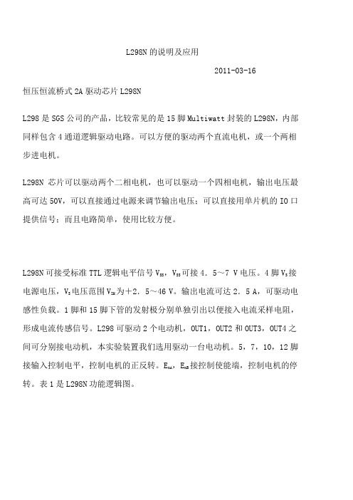
L298N的说明及应用2011-03-16恒压恒流桥式2A驱动芯片L298NL298是SGS公司的产品,比较常见的是15脚Multiwatt封装的L298N,内部同样包含4通道逻辑驱动电路。
可以方便的驱动两个直流电机,或一个两相步进电机。
L298N芯片可以驱动两个二相电机,也可以驱动一个四相电机,输出电压最高可达50V,可以直接通过电源来调节输出电压;可以直接用单片机的IO口提供信号;而且电路简单,使用比较方便。
L298N可接受标准TTL逻辑电平信号V SS,V SS可接4.5~7 V电压。
4脚V S接电源电压,V S电压范围V IH为+2.5~46 V。
输出电流可达2.5 A,可驱动电感性负载。
1脚和15脚下管的发射极分别单独引出以便接入电流采样电阻,形成电流传感信号。
L298可驱动2个电动机,OUT1,OUT2和OUT3,OUT4之间可分别接电动机,本实验装置我们选用驱动一台电动机。
5,7,10,12脚接输入控制电平,控制电机的正反转。
E nA,E nB接控制使能端,控制电机的停转。
表1是L298N功能逻辑图。
In3,In4的逻辑图与表1相同。
由表1可知E nA为低电平时,输入电平对电机控制起作用,当E nA为高电平,输入电平为一高一低,电机正或反转。
同为低电平电机停止,同为高电平电机刹停。
L298N控制器原理如下:图3是控制器原理图,由3个虚线框图组成。
下面是3个虚线框图功能:(1)虚线框图1控制电机正反转,U1A,U2A是比较器,V I来自炉体压强传感器的电压。
当V I>V RBF1时,U1A输出高电平,U2A输出高电平经反相器变为低电平,电机正转。
同理V I<V RBF1时,电机反转。
电机正反转可控制抽气机抽出气体的流量,从而改变炉体压强。
(2)虚线框图2中,U3A,U4A两个比较器组成双限比较器,当V B<V I<V A时输出低电平,当V I>V A,V I<V B时输出高电平。
V A,V B是由炉体压强转感器转换电压的上下限,即反应炉体压强控制范围。
- 1、下载文档前请自行甄别文档内容的完整性,平台不提供额外的编辑、内容补充、找答案等附加服务。
- 2、"仅部分预览"的文档,不可在线预览部分如存在完整性等问题,可反馈申请退款(可完整预览的文档不适用该条件!)。
- 3、如文档侵犯您的权益,请联系客服反馈,我们会尽快为您处理(人工客服工作时间:9:00-18:30)。
APPLICATION NOTEAN238/0488EASE STEPPER-MOTOR-DRIVE DESIGNHIGH-POWER,DUAL-BRIDGE ICsIn addition to simplifying design problems,a family of dedicated chips improves stepper-motor drive-circuit reliability by significantly reducing the component count.Figure 1:The Simplest Stepper-motor Drive Technique is the Basic L/R Configuration.Adding Series Re-sistors and Raising the Supply to Make an L/4R Drive Improves Torque at High Steps rates but Reduces Efficiency.The L293,L293E and L298N dual-bridge ICs (see box ,”inside the dual-bridge ICs”)significantly redu-ce the problems encountered in the design of step-per-motor drive circuitry.They can,for example,simplify the design and increase the efficiency ofconstant-current choppers.And with a single chip replacing the transistors and predriver stages,cir-cuit performance improves.Best of all,the devices have applications in complex as well as basic driver networks.1/8SIMPLEST DESIGN IS AN L/R DRIVE The simplest motor-drive configuration (fig.1)con-sists of a µC that performs the translator function in software (see box ,”Generating switching sequen-ces”)and drives the motor through a L293dual brid-ge.Only eight external components are required ;these are diodes that protect the device’s output transistors againstinductive spikes generatedwhen a winding de-energizes.The L293handles 1A continuous(for higher currentuse and L298N).However,if you plan to run the mo-tor continuously with two phases on,dissipation will be the limiting factor.You can improve the performance of this basic L/R drive by increasing the series resistanceand raising the supply voltage to restore the original phase cur-rent.At high speeds,torque improves,but efficiency decreases.Normally,you increase each winding’s resistance by a factor of four through the addition of a 3R series resistance,resulting in the L/4R drive.Dual-bridge driver ICs reducethe partscount ofbipolar steppermotors andsimplify design.The sche-matic of the L298N is functionally similar to those of the L293and L293E.INSIDE THE DUAL-BRIDGE ICsThe L293,L293E and L298N (figure)contain two po-wer-transistor bridges,predriver stages,control logic and protection circuitry.There’s a control input for each bridge and an enable input for each half bridge ;inputs connect directly to µCs,CMOS or TTL.The ICs inte-grate level shifters with a separate logic-supply pin.For current sensing,the L293E and L298N have external emitter connections.A single package drives a 2-phase bipolar stepper mo-tor,challenging the assumption held by many that uni-polar motors are easier to drive.You can use a bipolar motor -simpler and less expen-sive than a unipolar motor -without building complex power stages.Furthermore,you don’t have to worry about simultaneous conduction of a half bridge’s sour-ce and sink transistors -a basic problem with discrete-component bridge circuits.Chip design makes it impossible for both transistors to be on at the same time.Designers should also discard the mistaken idea that constant-current chopper drivers are complicated and expensive.You can build one with two bridge ICs and a few passive components.Type I O I O(PEA K)V S Package Sensing Connections L2931A 1.5A 36V DIP16L293E 1A 1.5A 36V DIP20One per Half Bridge L298N2A2.5A46VMultiwatt15One per BridgeAPPLICATION NOTE2/8MULTIPLE SUPPLIES BOOST PERFOR-MANCEA dual-level supply also improves the performance of a basic L/R circuit.A high supply voltage yields good torque characteristics when the motor is run-ning.A lower-than-rated voltage provides some hol-ding torque when the motor is at rest,therebysaving power when the motor is idle.Fig.2shows a suitable voltage-switch circuit.R x sets the holding current,which can be low because a permanent magnet or hybrid stepper motor provi-des some holding torque at zero current.However, make certain the L293’s motor-supply input never goes below the logic-supply voltage.While there’s no danger of damaging the device,it’s imposssible to drive the output transistors correctly under such conditions.The dual bridge’s enable inputs offera meansof ex-tending the chip’s flexibility.For example,you can connect them directly to the logic supply-no resi-stors are needed-to enable the chip permanently. As an alternative,use the enable inputs to disable the motor during the power-on reset sequence.In wave-drive and half-step modes,use the enable inputs to increase torque at high speeds.When a winding de-energizes,flux collapse is a function of the current-decay rate.During this decay,the de-energized winding opposes the efforts of the next winding in sequence,partially cancelling the torque.You can minimize this effect by disabling a bridge only when the winding it drives is turned off;becau-se the∆i/∆t of an inductor equals E/L,disabling the bridge acceleratesthe current decay.This action di-scharges the winding’s stored energy through its supply and maintains the terminal voltage E at V s plus two diode drops.If you were to leave the bridge enabled,the current would flow to ground through one diode and one transistor,and it would lower the terminalvoltage.This scheme doesn’t applywith dri-veswithtwophaseson becauseno winding ever de-energizes.Figure2:Switching the Supply to a Lower Volt-age when the Motor is Idle Saves Cur-rent without Compromising DrivingPower.Figure3:Maintaining a Constant-average Phase Current this Fixed-ripple Chopper Provides Improved Performance and Efficiency V REF Controls the Phase Current.APPLICATION NOTE3/8GENERATING SWITCHING SEQUENCESIn addition to selecting a motor and determining power-stage design,you must also decide how to generate the switchingsequences thatstepthe motor.Programming a µC or using a special piece of hardware called a tran-sistor accomplishes this task.Software translation is more economical,and it is the first choice for large-volume products.Fig.A shows a basic step procedure (a)that you can integrate into a routine (b);the routine executes a clockwise rotation of N steps at a fixed rate.The step rate is defined by a software loop,but you can also use programmed timer interrupts.Fig.A :A µC can generate the phase sequence (a)for a stepper motor.A routine (b)expands a single-step routine into are that executes a move of N steps.A simpler approach uses the software equivalent of a shift register.For example,you can load a 99(hex)into a register and take the phases from bits 0to 3.A Rotate Left instruction yields a clockwise step ;a Rotate Right instruction causes a counterclockwise move.When software translation ties up your µC,lighten the load by adding a hardware translator.In applications in-volving unidirectional motors,this logic circuit (fig.B)re-quires only one pulse for each step ;you’ll also need a direction signal (b)if your motor rotates in both direc-tions.By adding a 7408to a 2-phase translator,you can satisfy a wave-drive application (c),while the addition of two OR gates provides fast turn-off in wave-drive mode.Fig.B :Built a simple 2-phase hardware translatorusing a dual flip-flop,for single (a)or bidirec-tional (b)rotation.Add some extra ICs for wave-drive signals (c)and to provide fast turn-off (d).a)b)b)c)d)a)APPLICATION NOTE4/8Often aµC controls the translator,setting the direction line and providing a pulse for each step.Software is thus simplified,and if you use a programmed interrupt scheme,theµC is free to handle other tasks.Fig.C de-scribes an absolute-positioning routine for a step with a direction-control translator;Fig.D outlines how pro-grammed timer interrupts are used to relieve the bur-den on the C.Two special cases call for hardware translation.The first is in a system for which you have already designed in control circuitry to provide step and direction signals. The second case involves single-quantity and small-run applications,in which thecost of a fewICs is a small price to pay for simplified software.Figure C:For use with a Hardware Trans-lator this a Absolute-positioningRoutine Sets the Direction Lineand Sends the AppropriateNumber of Step Pulses. Figure D:To Set a motor Step Rate,usedProgrammed Timer Interruptsin Place of Software TimingLoops.Notes:Enter with de-sired position current po-sition in register or mem-APPLICATION NOTE5/8CHOPPER CIRCUIT OFFERS MORE EN-HANCEMENTSAdding a chopper circuit to maintain a constant-ave-rage phase current improves performance and effi-ciency.Fig.3showna simple constant-currentdrive that employs a dual bridge,dual comparator and a few passive components.This circuit requires an L293E,because this dual-bridge IC offers access to the lower emitter connections,thus letting you insert current-sensing resistors.Operation of this fixed-ripple chopper drive is strai-ghtforward.When theµC or translator activates a bridge,theincreasing load current raises thevoltage across the sensing resistor until it equals the com-parator’s reference voltage.The comparator then switches,clamping the translator signals through the diodes to deactivate the bridge.As the current decays,the voltage across the sensing resistor de-creases until it equals the comparator’s lower thre-shold.The comparator switches again,allowing the µC or translator to activate a bridge and restart the cycle.Aslong as the translatordrives the bridge,this sequence repeats to provide a constant-average phase current with fixed ripple.V ref adjuststhe lower current limit,while the compa-rator’s hysteresis sets the ripple,and hence the peak current.Although a divider establishes the va-lue of V ref in this case,you can employ the dual-sup-ply design approachand switch V ref toa lower value when the motor is idle.In addition,use of a D/A con-verter establishes V ref for micro-stepping applica-tions.This drive circuit,with its fixed-ripple current characteristics,is well suited for such service. FIXED-FREQUENCY CHOPPER IS MOTOR INDEPENDENTFig.3’s drive has some disadvantages.First,the chopper frequency depends on motor characteris-tics,and these parameters vary from unit to unit.In addition,it’s impossible to synchronize the chop-pers,and this shortcoming can cause trouble on the ground plane.Using a flip flop/comparator arrangement(fig.4)to develop a fixed-frequency chopper overcomes the-se problems.In this circuit,the NE555timer gene-rates negative pulses that reset the flip flops to enable the phase-controlsignalsfrom the translator. If these signals are set to energize a winding,theFigure4:This Fixed-frequency Constant-current Chopper Driver Enables the Synchronization of Several Drives,thus Minimizing Potential Ground-plane Problems.APPLICATION NOTE6/8Figure5:A Special Translator-chopper Control Circuit cuts the Drivers Components Count to the Mini-mum.current in that winding rises until the voltage across the sensing resistor switches the comparator,thus setting the flip flop.This disables the phase signals and deactivates the bridge.Current in the winding falls until the next clock pulseresets the flip flop,and the sequence repeats to maintain a constant cur-rent.CONTROLLER IC REDUCES COMPONENT COUNTIf you’re using a hardware translation and constant-current choppers,you can further reduce the com-ponent count by using a controller chip such as the L297–a20-pin DIP that houses a translator and a dual fixed-frequencychoppercircuit.Under the con-trol of step and direction inputs,the L297generates normal,wave-drive and half-step sequences.As shown in fig.5,the controller connectsdirectly to a dualbridge.Externalcomponentrequirementsare minimal:and RC network to set the chopper fre-quency and a resistive divider to establish the com-parator reference voltage(V ref).To accommodatemotorswith a phase currentasgreat as3.5A,replace the single dual-bridge ICwith two de-vices configured in parallel(input to input,enable to enable,etc)to form a single bridge.It’s extremely im-portant thatyou pair the half bridges–1with4and2 with3–to ensure optimum current sharing.Reprinted from EDN.11/24/83©1986CahnersPublishing Company Division ofReed Publishing USA.APPLICATION NOTE7/8APPLICATION NOTEInformation furnished is believed to be accurate and reliable.However,SGS-THOMSON Microelectronics assumes no responsibility for the consequences of use of such information nor for any infringement of patents or other rights of third parties which may result from its use. No license is granted by implication or otherwise under any patent or patent rights of SGS-THOMSON Microelectronics.Specifications mentioned in this publication are subject to change without notice.This publication supersedes and replaces all information previously supplied.SGS-THOMSON Microelectronics products are not authorized for use as critical components in life support devices or systems without express written approval of SGS-THOMSON Microelectronics.©1995SGS-THOMSON Microelectronics-All Rights ReservedSGS-THOMSON Microelectronics GROUP OF COMPANIESAustralia-Brazil-France-Germany-Hong Kong-Italy-Japan-Korea-Malaysia-Malta-Morocco-The Netherlands-Singapore-Spain-Sweden-Switzerland-Taiwan-Thaliand-United Kingdom-U.S.A.8/8。