ip stb platform
MuxLab 3G-SDI ST2110 over IP 无压缩网关转换器快速安装指南说明书
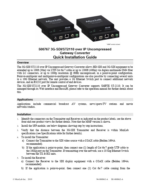
* MMF version shown500767 3G-SDI/ST2110 over IP UncompressedGateway ConverterQuick Installation GuideOverviewThe 3G-SDI/ST2110 over IP Uncompressed Gateway Converter allows HD-SDI and 3G-SDI equipment to be extended up to 100ft (30m) via UTP Cat 6a/7 cable or up to 1300ft (400m) via duplex multimode OM4 fiber with LC connectors, at up to 1080p resolution @ 60Hz uncompressed, in a point-to-point configuration. Point-to-multipoint and multipoint-to-multipoint configurations are also possible by connecting several units to a 10G Ethernet network. The unit provides a 1G Ethernet Switch port to connect additional network devices, and an RS232 port for remote control of end devices.The 3G-SDI/ST2110 over IP Uncompressed Gateway Converter supports SMPTE ST-2110. It can be managed through its Web interface and RestAPI, please refer to the operation manual for further details about this.ApplicationsApplications include commercial broadcast AV systems, news/sports/TV stations and movie networks/studios.Installation1.Identify the connectors on the Transmitter and Receiver as indicated on the product labels, see the abovefront and rear product views for further details. Note that the MMF version is shown.2.Install the SFP module, see below diagrams showing step by step instructions.3.Verify that the distance between the 3G-SDI Transmitter and Receiver is within MuxLabspecifications (see Specifications table for further details).4.To install the Transmitter:a)Connect the Transmitter to the SDI video source with a COAX cable (Belden 1694Arecommended).b)If the application is point-to-point, then connect one (1) length of Cat 6a/7 grade UTP cable tothe 10Gig port on the Transmitter. If transmitting over the network, use a 10 Gig Ethernet Switchbetween the TX & RX units.5.To install the Receiver:a)Connect the Receiver to the SDI display equipment with a COAX cable (Belden 1694Arecommended).b)If the application is point-to-point, then connect one (1) Cat 6a/7 cable coming from theTransmitter, to the 10Gig port on the Receiver. If transmitting over the network, use a 10Gig Ethernet Switch between the TX & RX units.6.If the configuration is a point-to-multipoint or multipoint-to-multipoint:a)You will need to use an Ethernet Switch with Gigabit ports and DHCP Server support. In additionIGMP Protocol support is required for the multipoint-to-multipoint case. Verify that the Ethernet Switch is configured correctly and that the DHCP Server is enabled and that the IGMP Protocol is enabled for multipoint-to-multipoint applications.b)Connect all Transmitters and Receivers to the Ethernet Switch.7.Connect the 12 VDC power supply to each Receiver and to an AC power outlet. Next connect eachTransmitter in the same manner. If power is present, the green power LED on each Transmitter and Receiver will illuminate.Note: Power ‘ON’ the 3G-SDI / ST2110 over IP uncompressed gateway converter only after all data connections have been made.8.Power ‘ON’ the 3G-SDI equipment and verify the image quality.9.The 500767 provides a 1GB Ethernet port to connect additional network devices (e.g. RestAPI controlsoftware).10.This product supports RS232 for remote control on end devices.11.The following diagram illustrates a typical point-to-multipoint LAN configuration.TroubleshootingThe following table describes some of the symptoms, probable causes and possible solutions in regard to the installation of the 3G-SDI/ST2110 over IP Uncompressed Gateway:If you still cannot diagnose the problem, please call MuxLab Customer Technical Support at 877-689-5228 (toll-free in North America) or (+1) 514-905-0588 (International).SFP Module Installation2321 Cohen Street, Montreal, Quebec, Canada. H4R 2N7Tel: (514) 905-0588 Fax: (514) 905-0589 Toll Free (North America): (877) 689-5228E-mail:******************:。
思科Catalyst 8500系列边缘平台数据表说明书

Cisco Catalyst 8500 SeriesEdge PlatformsData sheet Cisco publicContentsPlatform details 3 Foundation for Software-Defined WAN 4 Product overview 4 Overall platform benefits 8 Memory, storage, and accessory options 9 Optics and transceivers modules 10 Resiliency and high availability 10 Power supplies 11 Software requirements 12 Specifications 14 Safety and compliance 15 Licensing 16 Product Sustainability 17 Ordering information 18 Services 20 Warranty 21 Cisco Capital 21 Document history 22The Cisco Catalyst 8500 Series Edge Platforms are high-performance cloud edge platforms designed for accelerated services, multi-layer security, cloud-native agility,and edge intelligence to accelerate your journey to cloud.Platform detailsPlatforms and configurationsThe C8500-20X6C platform (Figure 1) allows all ports to be enabled simultaneously. It offers:●20x 1/10GE ports●6x 40/100GE portsThe C8500-12X4QC platform (Figure 2) allows for a maximum of 240GE ports to be enabled simultaneously. It offers:●12x 1/10GE ports●2x 40GE ports●2x 40/100GE portsThe C8500-12X platform (Figure 3) offers 12x 1/10GE ports.The C8500L-8S4X platform (Figure 4) offers 4x 1/10GE and 8x 1GE ports.Figure 1.C8500-20X6CFigure 2.C8500-12X4QCFigure 3.C8500-12X with 12x 1/10GE portsFigure 4.C8500L-8S4X with 4x 1/10GE and 8x 1GE portsNomenclature NoteCatalyst 8500 Edge Platforms refer to C8500-12X, C8500-12X4QC and C8500-20X6CCatalyst 8500L Edge Platform refers to C8500L-8S4XCatalyst 8500 Series Edge Platforms refer to Catalyst 8500 and Catalyst 8500L Edge Platforms together Foundation for Software-Defined WANCisco Catalyst 8500 Series Edge Platforms (Catalyst 8500 and Catalyst 8500L) with Cisco IOS XE SD-WAN Software delive r Cisco’s secure, cloud-scale SD-WAN solution for aggregation sites. The Catalyst 8500 Edge Platforms feature the all-new third-generation Cisco Quantum Flow Processor (QFP), the Catalyst 8500 Series Edge Platforms are built for services from the ground up. The Catalyst 8500L Edge Platform features an x86 based platform architecture that is purpose built to continue delivering the same experience as an ASR1000 platform. The Catalyst 8500 Series Edge Platforms are compact 1RU or 3U (Catalyst C8500-20X6C) devices with flexible interface options, including 1GE, 10GE, 40GE, and 100GE ports. Powered by Cisco IOS XE, fully programmable software architecture, and API support, these platforms can facilitate automation at scale to achieve zero-touch IT capability while migrating workloads to the cloud.Product overviewCatalyst 8500 Edge Platform Product highlightsTable 1.Catalyst 8500 Edge Platform Product highlightsTable 2.Catalyst 8500L Edge Platform Product highlightsTable 3 provides details on each platform’s configurations and port density. Table 4 shows the maximum port configurations for the Cisco Catalyst C8500-12X4QC platform.Table 3.Cisco Catalyst 8500 Series configurations and port density*All interfaces (total of 800 Gbps bandwidth) can be enabled simultaneously**Up to 240GE of ports can be enabled simultaneouslyTable 4.Maximum ports configurations for Cisco Catalyst C8500-20X6CTable 5.Maximum ports configurations for Cisco Catalyst C8500-12X4QC*When Bay 1 is set up in 100GE mode, no other ports available in Bay 0 or Bay 1.Figures 3 and 4 are a series of images that highlight the Cisco Catalyst C8500-12X4QC platfor m’s port options in each of its bays.Figure 5.Bay 0 + bay 1 port optionsFigure 6.Bay 2 port optionsTable 5a.Cisco controller mode (SD-WAN) performance specificationsTable 5b.Cisco autonomous mode (non SD-WAN) performance specificationsTable 5c.Cisco autonomous mode (non SD-WAN) system scalability*IMIX is average packet size of 352 Bytes packet size**Based on clear text traffic measurement from traffic generatorOverall platform benefitsAccelerated services with Cisco Software-Defined WANCisco SD-WAN is a set of intelligent software services that allow you to connect users, devices, and branch office locations reliably and securely across a diverse set of WAN transport links. Cisco Catalyst 8000 Series Edge Plat forms can dynamically route traffic across the “best” link based on up-to-the-minute application and network conditions for great application experiences. You get tight control over application performance, bandwidth usage, data privacy, and availability of your WAN links—control you need as your branches conduct greater volumes of mission-critical business with both on-premises and cloud controllers.Application optimizationEnsure that SD-WAN networks meet Service-Level Agreements (SLAs) and maintain strong performance, even if network problems occur. With multi-cloud access, you can accelerate your SaaS applications with a simple template push from the SD-WAN controller.Multi-layer securityYou can now move your traditional and complex WAN networks to a more agile software-defined WAN with integrated security. The Cisco Catalyst 8500 Series Edge Platforms feature on-premises and cloud-based security options.Application visibilityApplications and users are more distributed than ever, and the internet has effectively become the new enterprise WAN. As organizations continue to embrace internet, cloud, and SaaS, network and IT teams are challenged to deliver consistent and reliable connectivity and application performance over networks and services they don’t own or directly control.The Catalyst 8500 Series Edge Platforms are integrated with Cisco ThousandEyes internet and cloud intelligence. IT managers now have expanded visibility, including hop-by-hop analytics, into network underlay, proactive monitoring of SD-WAN overlay, and performance measurement of SaaS applications. This granular visibility ultimately lowers the Mean Time to Identification of Issues (MTTI) and accelerates resolution time. Cloud-native agility with programmable software architectureCisco continues to offer a feature-rich traditional IOS XE routing stack on the Cisco Catalyst 8000 Series Edge Platforms. IP Routing, IPSec, Quality of Service (QoS), firewall, Network Address Translation (NAT), Network-Based Application Recognition (NBAR), Flexible NetFlow (FNF), and many other features are part of Cisco IOS XE, a fully programmable software architecture with API support and a wide variety of protocols and configurations. With an integrated software image and a single binary file, you can now choose between Cisco IOS XE SD-WAN and Cisco IOS XE. And easily move from one to the other when you choose to do so.5G-readyThe Cisco Catalyst 8500 Series Edge Platforms are built for future 5G networks. These platforms support external cellular gateway modules with LTE/5G capability for improved throughputs and latency.Compact form factorThe Cisco Catalyst 8500 Series Edge platforms feature compact 1RU and 3RU platforms with rich interface options, including 1G, 10G, 40G, and 100G ports. Featuring the highly efficient third-generation QFP, the Cisco Catalyst 8500 Series Edge Platforms are built without compromising on performance and ports. Memory, storage, and accessory optionsTable 6.Cisco Catalyst 8500 Series C8500-20X6C memory, storage, and accessory optionsNote: MEM-C8500-64GB memory, SSD-M2SATA-480G SSD M.2 SATA 480 GB and C8500-ACCKIT3R-19 Cisco Mounting Brackets/accessory kit – 19 inches come standard as a default SKUTable 7.Cisco Catalyst 8500 Series C8500-12X and C8500-12X4QC memory, storage, and accessory optionsTable 8.Cisco Catalyst 8500L Edge Platform memory, storage, and accessory optionsOptics and transceivers modulesA full list of optics and transceivers is available at: https:///?si=C8500Resiliency and high availabilityPlatform redundancy is critical, as any downtime has direct impact to a customer’s business. The Catalyst 8500 Series Edge Platforms ship with high-efficiency dual power supplies by default for power supply redundancy. All Catalyst 8500 Edge Platforms support software redundancy with two IOS XE processes running on a single device (IOS XE routing mode) for additional control-plane resiliency.Power suppliesTable 9.Cisco Catalyst 8500-20X6C Series power supply specificationsTable 10.Cisco Catalyst 8500 Series power supply specifications for C8500-12X and C850012X4QCTable 11.Cisco Catalyst 8500L Edge Platform power supply specificationsRFID tags: Catalyst 8500 Series Edge Platforms have an embedded RFID tag that holds Serial Number and Product ID for easy asset and inventory management using commercial RFID readers.The RFID tag is external and can be easily removed if needed or can be unselected at the time of ordering. Software requirementsTable 12.Minimum software requirements for Cisco Catalyst 8500 Series Edge PlatformsTable 13.ThousandEyes requirementsTable 14.Software features and protocols for autonomous modeTable 15.Software features and protocols for controller mode* Support for C8500-12X and C8500-12X4QC only starting in 17.9.3., future release support will only be based on long-lived releases with the next supported release continuing in 17.12.x. Software releases 17.7, 17.8. 17.10 and 17.11 will not support broadband features. SpecificationsMechanical specificationsTable 16.Mechanical specifications for the Cisco Catalyst Series 8500 Edge PlatformsSafety and complianceTable 17.Safety and compliance specifications for the Cisco Catalyst Series 8500 Edge PlatformsLicensingAll Cisco Catalyst 8500 Series Edge Platforms are offered only with a Cisco DNA Software subscription. Only Cisco DNA Advantage and Cisco DNA Premier are available for the Cisco Catalyst C8500L, C8500-12X and C8500-12X4QC Series Edge Platforms. Cisco DNA Advantage is only offered on the C8500-20X6C Series Edge Platform.For more details, refer to this C8500 ordering guide.Cisco Smart LicensingCisco Smart Licensing is a flexible licensing model that provides you with an easier, faster, and more consistent way to purchase and manage software across the Cisco portfolio and across your organization. And it’s secure – you control what users can access. With Smart Licensing you get:●Easy Activation: Smart Licensing establishes a pool of software licenses that can be used across theentire organization—no more PAKs (Product Activation Keys).●Unified Management: My Cisco Entitlements (MCE) provides a complete view into all of your Ciscoproducts and services in an easy-to-use portal, so you always know what you have and what you are using.●License Flexibility: Your software is not node-locked to your hardware, so you can easily use andtransfer licenses as needed.To use Smart Licensing, you must first set up a Smart Account on Cisco Software Central (). For a more detailed overview on Cisco Licensing, go to /go/licensingguideCisco ThousandEyesA valid ThousandEyes agent license is required to activate the ThousandEyes agent. Existing ThousandEyes subscriptions can be leveraged on eligible Catalyst 8500 Series platforms. Additional ThousandEyes subscription information can be found here.Product SustainabilityTable 18.Cisco Environmental Sustainability InformationOrdering informationTable 19.Orderable SKUs for the Cisco Catalyst 8500 Series Edge PlatformsTable 20.Orderable SKUs for the Cisco Catalyst 8500L Edge PlatformServicesCisco Customer Experience Support Services for Catalyst 8000 platforms and Cisco DNA Software for SD-WAN and RoutingThis section discusses the Cisco Support Services available for Catalyst 8000 platforms and associated Cisco DNA Software for SD-WAN and Routing, as well as optional Support Service offers.●Catalyst 8000 platforms: Cisco Solution Support is the default and recommended Cisco SupportService. However, Cisco Solution Support is not mandatory; it can be removed or replaced with another Cisco support service or partner service per the customer’s preference.●Cisco DNA Software for SD-WAN and Routing: Cisco Solution Support is the default Cisco supportservice. However, Cisco Solution Support is not mandatory; the customer may choose to use the Cisco Subscription Embedded Software Support included with the purchase of this software.Note:●When Solution Support is selected, it must be ordered on both the Catalyst 8000 platform and CiscoDNA Software for SD-WAN and Routing for complete customer entitlement to this premium support service.●SD-WAN and Routing, with both Solution Support or Cisco Subscription Embedded Software Support,customers are entitled to maintenance releases and software updates for Cisco DNA SD-WAN andRouting software only.The support for the Catalyst 8000 platform’s OS and network stack, along with OS updates, is covered by the support contract on the Catalyst 8000 platform.Cisco Solution Support is a premium support purpose-built for today’s multiproduct, multivendor network environments and provides:● A primary point of contact centralizing support across a solution deployment●Solution, product, and interoperability expertise●No requirement for customers to isolate their issue to a product to open a case●30-minute service response objective for Severity 1 and 2 cases●Prioritized case handling over product support cases●Product support team coordination (Cisco and Solution Support Alliance Partners)●Accountability for multiproduct, multivendor issue management from first call to resolution, no matterwhere the issue residesLearn more about Cisco Solution Support at https:///go/solutionsupport.Cisco Subscription Embedded Software Support includes:●Access to support and troubleshooting via online tools and web case submission. Case severity orescalation guidelines are not applicable.●Cisco Technical Assistance Center (TAC) access 24 hours per day, 7 days per week to assist bytelephone, or web case submission and online tools with application software use and troubleshooting issues.●Access to https://, providing helpful technical and general information on Ciscoproducts, as well as access to Cisco’s online Software Center library.Note: No additional products or fees are required to receive embedded support for Cisco DNA Software for SD-WAN and Routing. However, if using embedded support for this software, hardware support for the Catalyst 8000 platforms must be purchased separately, as Cisco Subscription Embedded Software Support does not cover hardware. In this case, Cisco Smart Net Total Care Service is recommended for Catalyst 8000 platforms.WarrantyCisco Catalyst 8500 Series Edge Platform come standard with a Cisco Limited 1-Year Return To Factory Hardware Warranty. For more information, refer to:https:///c/en/us/products/warranties/warranty-c99-744450.html.Cisco CapitalFlexible payment solutions to help you achieve your objectivesCisco Capital® financing makes it easier to get the right technology to achieve your objectives, enable business transformation, and help you stay competitive. We can help you reduce the total cost of ownership, conserve capital, and accelerate growth. In more than 100 countries, our flexible payment solutions can help you acquire hardware, software, services, and complementary third-party equipment in easy, predictable payments. Learn more.Document historyTable 21.Document historyPrinted in USA C78-744089-07 03/23。
IP STB 功能规范3.4(终稿)_中国网通
IP STB功能规范中国网通研究院2004年7月目录1IP STB基本功能 (5)1.1 视频点播(VOD)功能 (5)1.2 组播频道功能 (5)1.3 INTERNET浏览及邮件服务 (6)2IP STB可选功能 (6)2.1 可视电话功能 (6)2.2 炒股功能 (6)2.3 视频会议功能 (6)2.4 远程教育功能 (7)2.5 游戏功能 (7)2.6 DVD功能 (7)2.7 卡拉OK功能 (7)2.8 F LASH播放功能 (7)2.9 视频、图片的广告插播功能 (7)2.10 其他功能 (8)3遥控器功能 (8)3.1 操作基本原则 (8)3.1.1遥控器使用要求 (8)3.1.2基本按键及功能 (8)3.2.1电话功能 (11)3.2.2手写输入功能 (11)3.2.3中文输入法 (11)3.2.4其他功能 (12)4STB控制面板功能 (12)5外设接口功能 (13)5.1 基本接口 (13)5.1.1基本视频接口 (13)5.1.2基本音频接口 (14)5.1.3基本网络通信接口 (14)5.2 可选接口 (14)5.2.1可选视频接口 (14)5.2.2可选音频接口 (14)5.2.3可选网络接口 (14)5.2.4管理认证接口 (15)5.2.5其他接口 (15)6EPG (15)7业务连接及认证功能 (15)7.1 网络连接功能 (15)7.2 用户认证功能 (16)8其他相关功能 (16)8.1 IP STB解码器 (16)8.2 IP STB浏览器 (17)8.3 IP STB播放器 (17)8.4 软件升级功能 (18)8.5 下载功能 (18)8.6 信息安全 (18)8.6.1网络防护要求 (19)8.6.2内容保护要求 (19)8.6.3用户安全要求 (19)8.7 所支持软件接口(可选) (19)1IP STB基本功能IP STB接入宽带网络,通过用户身份识别和认证后,可以收看免费视频点播节目及组播频道的节目。
STB各接口解释
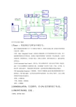
信号首先从接口输进1.Tuner :将射频信号降为中频信号。
通过天线接收到射频信号并下行变频为中频信号,高频头是通过I2C总线技术来控制进行选台的(调谐)。
①I2C(Inter-Integrated Circuit)总线是由PHILIPS公司开发的两线式串行总线,用于连接微控制器及其外围设备。
是微电子通信控制领域广泛采用的一种总线标准。
它是同步通信的一种特殊形式,具有接口线少,控制方式简单,器件封装形式小,通信速率较高等优点。
②AGC(Automatic Gain Control),缩写为,即自动增益补偿(或自动电平控制)的意思,AGC可以自动调整放大电路的放大量。
该电路最广泛应用于无线(声波、红外线,无线电等)接收电路中。
使接收器在离发射源一定距离范围内都能保持稳定的输出。
③IF (intermediate frequency) 中频抑制。
用来在中频衡量AM或FM调谐器抑制外来干扰的能力,数字越大越好。
包含很多晶体管和电阻器的一块小型电子器件,它是大多数音频组件的基本组成部分。
射频:> 500M Hz中频:50MHz ~ 500MHz基带:< 50MHz2.DEMODULATER:信道解码,给CPU提供解调后TS流。
3. FRONT PANEL 前板:①GPIO:通用输入输出②SAR(Segmentation And Reassembly):分段和重组。
用于异步传输模式(ATM)的通信,在TCP/IP 中,这一方法称fragmentation。
ATM适配层分为两子层:(1)CS(Convergence)子层提供标准的接口。
(2)SAR(Segmentation And Reassembly)子层对数据进行分段和重新装配③PWM:脉冲宽度调制(Pulse Width Modulation),是利用微处理器的数字输出来对模拟电路进行控制的一种非常有效的技术,广泛应用在从测量、通信到功率控制与变换的许多领域中4.SMART CARD 智能卡:接收电视的授权卡。
网络管理员练习题及答案
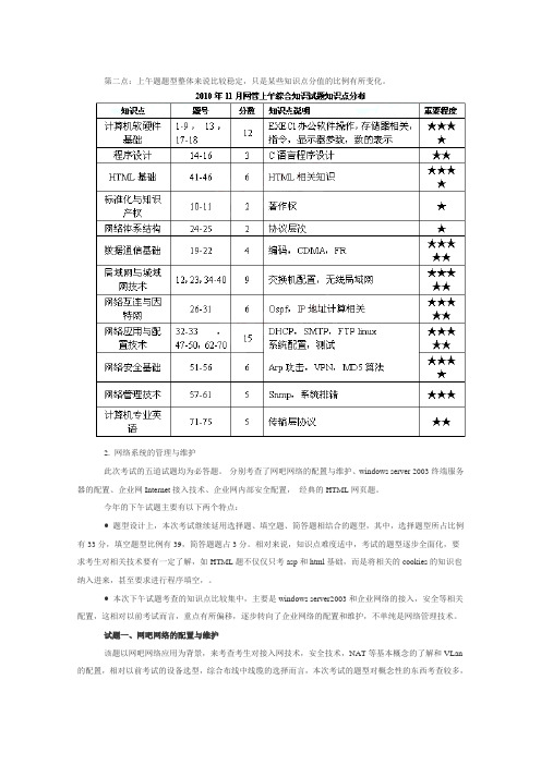
第二点:上午题题型整体来说比较稳定,只是某些知识点分值的比例有所变化。
2. 网络系统的管理与维护此次考试的五道试题均为必答题。
分别考查了网吧网络的配置与维护、windows server 2003终端服务器的配置、企业网Internet接入技术、企业网内部安全配置,经典的HTML网页题。
今年的下午试题主要有以下两个特点:● 题型设计上,本次考试继续延用选择题、填空题、简答题相结合的题型,其中,选择题型所占比例有33分,填空题型比例有39,简答题题占3分。
相对来说,知识点难度适中,考试的题型逐步全面化,要求考生对相关技术要有一定了解,如HTML题不仅仅只考asp和html基础,而是将相关的cookies的知识也纳入进来,甚至要求进行程序填空,。
● 本次下午试题考查的知识点比较集中,主要是windows server2003和企业网络的接入,安全等相关配置,这相对以前考试而言,重点有所偏移,逐步转向了企业网络的配置和维护,不单纯是网络管理技术。
试题一、网吧网络的配置与维护该题以网吧网络应用为背景,来考查考生对接入网技术,安全技术,NAT等基本概念的了解和VLan 的配置,相对以前考试的设备选型,综合布线中线缆的选择而言,本次考试的题型对概念性的东西考查较多,相对来说,这些都是基础概念都是网络管理员必须要掌握和理解的概念,试题的难度和范围都控制在基本知识点和概念的范围内。
试题二、windows server 2003终端服务器的配置该题以在windows server 2003终端服务器配置为基础,要求考生掌握与终端服务相关的基本概念,协议,端口,用户权限和客户端配置的了解,这道题相对比较简单,即使经验不丰富,题目图示的信息也能轻松选择出正确的答案。
试题三、企业网Internet接入技术本题考察的知识点比较灵活,涉及到拓扑图和DHCP服务,Ping命令的应用。
粗看上去感觉题目较复杂,但是仔细从图中观察都可以获得结果。
RippleOS(7.0)桌面吸顶AP使用说明说明书

RippleOS(7.0)固件使用手册RippleOS(7.0)固件使用手册 (1)1.设备绑定运营平台商铺操作 (3)2.设备解绑 (4)二、网络设置 (5)1.接口管理 (5)2.外网负载 (7)3.无线设置 (8)4.QOS智能限速 (9)5. 终端管理 (11)三、高级设置 (12)1.设备管理 (12)2.免认证设置 (12)3.AC设置 (13)4.端口转发 (14)四、系统设置 (15)五、故障管理 (15)六、路由器首页 (16)七、新增-扫码上网 (17)一、登录路由器路由器初始状态下,电脑用网线接到设备LAN口或电脑无线连接到路由wifi,自动获取到IP 地址后,打开浏览器输入路由器默认登录地址192.168.10.1,进入路由器登录界面:图1 路由器登录界面注:设备默认初始密码为admin。
如果忘记登录密码,请重置路由器。
重置路由器方法为:在设备正常运行时,按下复位键,10秒后松开,设备灯会全闪一下,之后设备会自动重启,重置路由器完成。
1.设备绑定运营平台商铺操作路由器连接到外网后,在路由器首页点击“立即绑定云端平台”按钮后,会显示绑定序列号,点击“立前往绑定”可跳转到运营平台。
图2 设备绑定界面注:需要成功连接外网才会出现绑定按钮。
在运营平台商铺内选择“设备绑定”----输入设备序列号完成设备绑定。
图3 运营平台商铺列表界面图4 设备绑定输入框【提示】设备绑定后,设备管理页面如下:图5 设备绑定成功界面设备解绑:登录运营平台-商铺列表-管理商铺-设备管理-解除绑定图6 运营平台设备解绑界面二、网络设置1.接口管理外网设置主要功能:配置外网口(WAN)上网方式,联通互联网。
外网(WAN)口设置,选择与自己宽带网络对应的协议类型。
如使用上端路由分配的IP地址则选择DHCP客户端;如上端为Modem,需要设备拨号,选择宽带账号(PPPOE),并填入账号和密码,进行拨号;如使用固定IP地址,选择静态地址,并填入指定的IP地址,子网掩码,出口网关,DNS等。
博通面向中国市场推介新一代IP STB SoC方案
AVC VC 1 和 一。
两 款芯 片 可以 与博 通 现 有的 DV R媒 体 服 务器解 决方 案 系列 互补 , 帮助 服务 将 提 供商 经济 实惠 地在 客 户机一 务器 部署 服 模 式 以 及 低 成 本 独 立 部 署 模 式 中扩 展 IT P V服 务 ,如 连 网 DV R和 I P视 频服 务 。
Dv R B、 中 国 A iX、 MV VS以 及 MP G一 E 2、
戏 实 时 自动 转 换 为 3 立体 效 果 。 D V D 3T Pa l y的配 置 要 求 包 括 支 持 3 io D Vs n技 i
术 Ge oc U。 n o 7Vit F re GP Wid ws / s a系统 。
的音 频 编 解 码 器 ,具 备 3个 串行 音 频 接
景信 息 科 技 公 司 (e gn S s m ) 总 T l et yt s和 e e
部位 于 台 湾 的 宽 带 无 线 解 决 方 案 供 应 商 In c mm 推 出 首款 基 于 A do n oo n ri d操作 系
度 的观 看 体验 和 S + D画 中画 ( I ) DS PP 功 能 。支 持 H MI. 接 口, D I 3 大大提 升 了标清
Cl 表 示 未 来 还 会 增加 数 字 电视 功 能 。 Of l l m
N D、 l V 3 1 ,Pa y电视 亮 相
Comp t X2 ue 01 0
自动 对 焦 镜 头 、. 网络 连 接 、 — i 35 G WiF 以
及 模 拟 电视 功 能 , 旨在 满 足 公 众 对 功 能 丰 富 的 触 屏 智 能 手 机 越 来 越 浓 厚 的 兴 趣 ,同 时 以 明 显 低 于 当 前 同 类 产 品 的价 格 进 入 这 一 市 场 。 市 场 研 究 公 司 G r at — n rD t u s 表 示 。智 能 手 机 市 场 预 计 e a q et a
IPTV STB 案例集(V100R002_01)
文档版本 发布日期
01 2012-01-06
华为技术有限公司
版权所有 © 华为技术有限公司 2012。 保留一切权利。 非经本公司书面许可,任何单位和个人不得擅自摘抄、复制本文档内容的部分或全部,并不得以任何形式传 播。
商标声明
和其他华为商标均为华为技术有限公司的商标。 本文档提及的其他所有商标或注册商标,由各自的所有人拥有。
1.1 开机至 85%无法接入平台............................................................................................................................. 1 1.2 对接中兴光猫使用 DHCP 方式无法连接 EPG ............................................................................................ 2 1.3 机顶盒更新开机画面后不能正常启动 ......................................................................................................... 4 1.4 开机至 85%无法接入 EPG ............................................................................................................................ 5 1.5 PPPoE 方式接入进度条停在 52%.................................................................................................................. 5 1.6 无法正常启动并提示 127 错误 ..................................................................................................................... 8 1.7 使用命令播放节目出现死机 ....................................................................................................................... 10 1.8 PPPoE 方式接入机顶盒断链........................................................................................................................ 12
IPTV疑难故障处理手册
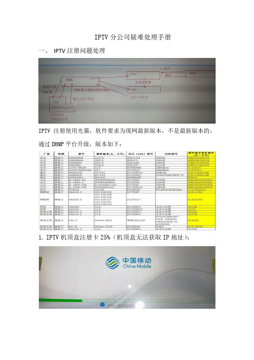
IPTV分公司疑难处理手册一、IPTV注册问题处理IPTV注册使用光猫,软件要求为现网最新版本,不是最新版本的,通过DHMP平台升级,版本如下:1.IPTV机顶盒注册卡25%(机顶盒无法获取IP地址);排查思路:⑴网络问题,BRAS上无法学习到机顶盒MAC地址BRAS上通过display aaa online-fail-record mac-address xxxx-xxxx-xxxx(MAC地址)命令查询,无任何数据,则为BRAS未学习到机顶盒MAC。
1)检查OLT是否学习到机顶盒MAC,无法学习则检查OLT是否有内外层转换数据,光猫或机顶盒是否有问题;(内层VLAN 250~499、3501~3899,外层VLAN 4036~4094,组播VLAN 4035)2)检查OLT上行、9312是否透传VLAN,BRAS数据是否配置正确OLT9312⑵IPOE认证失败或DHCP Server问题BRAS上通过display aaa online-fail-record mac-address xxxx-xxxx-xxxx(MAC地址)命令查询,有上线失败记录则根据报错具体核查。
1)上线失败原因显示RADIUS authentication reject(认证拒绝)检查机顶盒IPOE内置账号(cqmciptv@iptv)是否为空或错误,机顶盒先恢复出厂设置,仍然为空或错误则更换机顶盒,更换机顶盒后问题仍然存在则更换光猫,Radius和DHCP报错同时出现,先处理Radius 报错;2)上线失败原因只显示DHCP报错,可先核查DHCP服务端是否有问题,是否收到 Radius 认证通过报文,未收到认证通过报文则按照第一步Radius认证拒绝处理。
2.IPTV机顶盒注册卡50%(连接TMS平台失败);⑴注册卡50%,机顶盒IPOE错误获取到192.168.1.X的IP地址1)检查DHMP系统是否成功发下数据,如下发失败则核实DHMP平台下发失败原因并处理。
中国联通IPTV体系架构技术规范(上)介绍
4.2.3.5 SP 管理
系统可以引入 SP,发布内容、开展业务;要求对 SP 有如下管理功能: 1.系统能够创建 SP 帐号,录入 SP 信息、分配 SP 管理员帐号; 2.系统能够限定 SP 开展的业务、频道,只允许 SP 发布开通的业务、频道范围的内容; 3.系统能够限定 SP 发布内容的分布范围,SP 内容只能分发到限定范围内的流媒体服 务设备上; 4.系统支持 VCDN,对 SP 内容占用资源进行分配;保证 SP 内容在 VCDN 范围内分 发;
中国联合通信集团公司
IPTV 体 系 架 构 技 术 规 范
IPTV A r c h i t e c h t u r e Te c h n o l o g y Specification版 本 号 : 1 Nhomakorabea 0.0
╳ ╳ ╳ ╳ -╳ ╳ -╳ ╳ 发 布
╳ ╳ ╳ ╳ -╳ ╳ -╳ ╳ 实 施
BSSP
P
M 运营支撑系统
Q DRM系统
业务支撑系统
L 业务管理系统
网管系统 N
节
F
H
I
目
内容制作
B 内容管理
D
电子
IP
内
系统
系统
节目
机终
容
单
顶端
A
E
C 系统 K
盒系
承 载
流媒体
增值业务
服务 J
系统
G
系统
网
络 内容系统
统
计 算 机
增值业务提供商
图 3 联通 IPTV 系统模块和接口关系图
第 4 页 共 142 页
4.1.2 IPTV 系统分层结构
Cisco SCE8000 10GBE平台安装和配置指南(版本3.1.6S)说明书

C H A P T E R2-1Cisco SCE8000 Installation and Configuration Guide, Rel 3.1.6SOL-16478-042Introduction to the Cisco SCE8000 PlatformThis chapter provides an introduction to the Cisco SCE8000 10GBE platform, the Service Control hardware component.•SCE Platform Information, page 2-1•Service Control Module—SCE8000-SCM-E, page 2-3•SIP and SPA Introduction, page 2-4•SCE8000-SIP Status LEDs, page 2-7•1-Port 10 GBE SPA Interface Module, page 2-7•Cisco SCE8000 Optical Bypass Module, page 2-9•Checking the Shipping Container Contents, page 2-14•Cisco SCE8000 Installation Checklist, page 2-15SCE Platform InformationThe Service Control Engine (SCE) platform, which is the hardware component of the Cisco service control solution, is designed to support observation, analysis, and control of Internet and IP traffic (Figure 2-1).Chapter2 Introduction to the Cisco SCE8000 Platform SCE Platform InformationFigure2-1Cisco SCE8000 PlatformTable2-1 summarizes model information for the Cisco SCE8000 platform.T able2-1SCE Platform Model InformationModel number Cisco SCE8000 10 GBELink Type10 Gigabit EthernetNumber of Ports 2 or 4Number of Links 1 or 2The Cisco SCE8000 is a transparent element with 10 GBE links service throughput. It can be installedinline in the network where all traffic passes through it, or in receive-only mode where it receivesreplication of the traffic through SPAN ports or optical splitters.The Cisco SCE8000 supports the following network insertion models:•Single appliance (inline)•Single appliance (receive-only)•MGSCP configurationThe Cisco SCE8000 platform is a 4-slot chassis hosting the following modules:•One or two service control modules (SCE8000-SCM-E) that each contain special-purpose, fast-path chipset, traffic processors, and control processor.•One SPA Interface Processor card (SCE8000-SIP) that holds up to four SPA 10 GBE interface modules.•One optional optical bypass module hosting panel that holds up to two optical bypass modules.In addition, the Cisco SCE8000 chassis contains two power supply modules in a 1+1 configuration, aswell as a fan tray module.Cisco SCE8000 Installation and Configuration Guide, Rel 3.1.6SOL-16478-042-3Cisco SCE8000 Installation and Configuration Guide, Rel 3.1.6SOL-16478-04Chapter 2 Introduction to the Cisco SCE8000 PlatformService Control Module—SCE8000-SCM-EChapter2 Introduction to the Cisco SCE8000 Platform SIP and SPA IntroductionT able2-3SCE8000-SCM-E LED Description (continued)LED DescriptionOptical Bypass•Steady amber—The optic bypass module is directed to pass traffic through theCisco SCE8000.•Unlit—The optic bypass module (if present) connects link fibers directly, andtraffic bypasses the Cisco SCE8000.On a slave SCE8000-SMC_E module (in slot 2), this LED is always off.This functionality is consistent even when the Cisco SCE8000 is powered off.Master Indicates the master service control module•Steady green—Master service control module•Unlit—Slave service control moduleMng interface The Mng interface LEDs indicate the operational status of the Cisco SCE8000out-of-band LAN-based management port, as follows:•Link/ActiveSteady green—Port link is upFlashing green—Activity on the port linkUnlit—Port link is down•SpeedUnlit—Port is set to 10 MbpsSteady green—Port is set to 100 MbpsSteady amber—Port is set to 1000 MbpsOn a slave SCE8000-SMC_E module (in the second slot), this LED is always off.SIP and SPA IntroductionSIPs and SPAs are carrier card and port adapter architectures used to increase modularity, flexibility, anddensity across Cisco routers for network connectivity. This section describes SIPs and SPAs andprovides some guidelines for their use.•SPA Interface Processors, page2-4•Specifying a SIP Subslot Location for a SPA, page2-5•Shared Port Adapters, page2-5•Modular Optics, page2-6•XFP Connections, page2-6SPA Interface ProcessorsThe SIP module supported by the Cisco SCE8000 chassis is the SCE8000-SIP. General characteristicsof a SIP include:• A SIP is a carrier card that inserts into a slot in the chassis like a line card. It provides no network connectivity on its own.Cisco SCE8000 Installation and Configuration Guide, Rel 3.1.6SOL-16478-042-5Cisco SCE8000 Installation and Configuration Guide, Rel 3.1.6SOL-16478-04Chapter 2 Introduction to the Cisco SCE8000 PlatformSIP and SPA Introduction2-6Cisco SCE8000 Installation and Configuration Guide, Rel 3.1.6SOL-16478-04Chapter 2 Introduction to the Cisco SCE8000 PlatformSIP and SPA IntroductionNoteChapter2 Introduction to the Cisco SCE8000 PlatformSCE8000-SIP Status LEDsT able2-4XFP Port Cabling SpecificationsXFP Wavelength (nm)Fiber TypeXFP-10GLR-OC192SR1310SMFXFP-10GER-OC192IR1550SMFXFP-10GZR-OC192LR1550SMFXFP-10G-MM-SR850MMFQualified XFPs include an optical transmitter and receiver pair integrated with clock and data recovery(CDR) integrated circuits. XFPs provide high-speed serial links at 10.3125 Gbps on single-mode fibers.The transmit side recovers and retimes the 10 Gbps serial data and passes it to a laser driver. The laserdriver biases and modulates a laser, enabling data transmission over fiber through an LC connector. Thereceive side recovers and retimes the 10 Gbps optical data stream from a photo detector trans impedanceamplifier and passes it to an output driver.To identify technology type and model, see the label on the XFP. XFP dimensions are:•Height—12.5 mm•Width—18.35 mm•Length—71.1 mmThe XFP operating temperature range is 0°C to 70°C.SCE8000-SIP Status LEDsTable2-5 describes the SCE8000 status LEDs.T able2-5SCE8000-SIP LEDLEDs DescriptionStatus•Green—Operational•Flashing Amber—Electrical bypass in operation•Red—Not initialized or failed•Unlit—No power1-Port 10 GBE SPA Interface ModuleThe SCE8000-SIP:•Is installed in slot 3 of the Cisco SCE8000 chassis.•Hosts up to 4 single-width, single-height 1-port 10 GBE SPA interface modules (Figure2-6).In the Cisco SCE8000, the SPA interface module must be configured with either:•Two 1-port 10 GBE SPAs (in the upper two subslots), or•Four 1-port 10 GBE SPAsCisco SCE8000 Installation and Configuration Guide, Rel 3.1.6S OL-16478-042-8Cisco SCE8000 Installation and Configuration Guide, Rel 3.1.6SOL-16478-04Chapter 2 Introduction to the Cisco SCE8000 Platform1-Port 10 GBE SPA Interface ModuleChapter2 Introduction to the Cisco SCE8000 PlatformCisco SCE8000 Optical Bypass ModuleCisco SCE8000 Optical Bypass Module•Optical Bypass Functionality, page2-9•Optical Bypass Module: OPB-SCE8K, page2-10The Cisco SCE8000 platform optical bypass module preserves the service provider 10 GBE links underall circumstances. Upon power failure, the bypass is automatically activated. It can also be activated bythe Cisco SCE8000 software.The Cisco SCE8000 platform already includes an internal electrical bypass, but we recommended thatyou use the optical bypass module for addressing the following scenarios:•During platform reboot (SW reload)—If the external bypass module is not used, there is a 5-second period (at most) during which the link is forced down (cutoff functionality).•During a power failure—The Cisco SCE8000 has two power supplies. A power failure occurs only if both of them fail.If the Cisco SCE8000 platform must be replaced, it is possible to remove the bypass modules from theSCE8000 chassis without disconnecting them from the network and then reinstall them in the new SCEplatform. Traffic links are preserved even in a case of complete failure and replacement of the CiscoSCE8000 platform. See the “Replacing Optical Bypass Module without Disrupting Traffic on Link”section on page9-26.Optical Bypass FunctionalityThe optical bypass module is connected bump-in-the-wire in the 10-GBE link. It is then connected to theCisco SCE8000 platform with two types of connections:•10GBE optical connections for data link traffic—10 GBE connections from the optical bypass module to one pair of the 10 GBE SPA ports.•Control connection—Connection to the RJ-11 External Bypass connector on the SCE8000-SCM, so the optical bypass is activated if the Cisco SCE8000 platform fails.Optical Bypass Module ConnectivityThe optical bypass module functions as follows (Figure2-7):•Under normal conditions, the bypass module directs traffic to flow through the Cisco SCE8000.•Under failure conditions, the optical bypass shortcuts the interfaces that are connected to the traffic link, and all traffic flows through the optical bypass module, bypassing the SCE platform.Cisco SCE8000 Installation and Configuration Guide, Rel 3.1.6S OL-16478-042-10Cisco SCE8000 Installation and Configuration Guide, Rel 3.1.6SOL-16478-04Chapter 2 Introduction to the Cisco SCE8000 PlatformCisco SCE8000 Optical Bypass ModuleCisco SCE8000 Installation and Configuration Guide, Rel 3.1.6SOL-16478-04Cisco SCE8000 Optical Bypass ModuleOptical Bypass Module SpecificationsFiber Cable TypeThe fiber cable type within the Optical Bypass Module area as follows:•OPB-SCE8K-MM: 50 um core.•OPB-SCE8K-SM: SMF-28Maximum optical path (fiber length of two ports) is 600m.Switching TimeSwitching time is measured from trigger to stable 90% optical output.•Typical switching time: 3 ms •Maximal switching time: 10msFan AssemblyThe system fan assembly, located in the chassis, provides cooling air for the installed modules (Figure 2-9).T able 2-8Optical Bypass Module PortsPort Quantity DescriptionConnect This Port to…10 GBE line port410GBE ports A through DDuplex LC, panel mount adaptor for LC/UPC connectors SPA interfaces on the Cisco SCE8000.Refer to the “Cabling the 10GBE Line Interface Ports: Using the External Optical Bypass Module” section on page 6-10 for information.CTRL1RJ-11 portRJ-11 optical bypass port on the SCE8000-SCM-ET able 2-9Optical Bypass Module LEDsLEDs DescriptionStatusThe Status LED indicates the operational status of the optical bypass module, as follows:•Green—Bypass module has been de-activated (traffic flows through the Cisco SCE8000 platform)•Off—Bypass module is active (traffic does not flow through the Cisco SCE8000 platform)2-12Cisco SCE8000 Installation and Configuration Guide, Rel 3.1.6SOL-16478-04Cisco SCE8000 Optical Bypass Module2-13Cisco SCE8000 Installation and Configuration Guide, Rel 3.1.6SOL-16478-04Cisco SCE8000 Optical Bypass ModuleCisco SCE8000 Installation and Configuration Guide, Rel 3.1.6SOL-16478-04Checking the Shipping Container ContentsPower Supply CoolingPower supplies have built-in fans and are completely self-cooling. Air enters from the right of the fan and exits through the left.Load-SharingWith two power supplies, each power supply concurrently provides approximately half of the required power to the system. If one power supply fails, the second power supply immediately assumes full power to maintain uninterrupted system operation. The second power supply enables load sharing and fault tolerance automatically; no software configuration is required.Checking the Shipping Container ContentsUse the Cisco SCE8000 Component List to check the contents of the Cisco SCE8000 platform shipping container.TipWhen you unpack the Cisco SCE8000, do not discard the shipping container. Flatten the shipping cartons and store them with the pallet. You may need these containers if you move or ship the Cisco SCE8000 in the future.Cisco SCE8000 ComponentsTable 2-10 lists the components of the SCE8000 system.T able 2-10Cisco SCE8000 Component ListComponentDescriptionCisco SCE8000 platform•Cisco SCE8000-SCM-E •Cisco SCE8000-SIP • 2 or 4 SPA Jacket cards • 2 or 4 XFP OpticsXFP optic modules.• 2 Cisco PWR-2700-AC/4 or 2 Cisco PWR-2700-DC/4 •SCE8000-FANCisco SCE8000 10 GBE chassis configured with the following components:•Cisco SCE8000 service control module•Cisco SCE8000 SPA Jacket card Interface Processor •SPA Interface. See below the list of supported SPA models.•See below the list of supported XFP models •Cisco power supply units, AC or DC.Hot swappable, redundant power supply, compatible with Cisco 7604 router.•Redundant fan unit.AccessoriesThe following accessories might arrive in separate shipping containers:Cisco SCE8000 Installation ChecklistT able2-10Cisco SCE8000 Component List (continued)Component DescriptionManagement cables•Gigabit Ethernet cable for connecting to theManagement ports•RS-232 serial cables (DB-9 to RJ-45 and DB-25 toRJ-45) for connecting to a local terminalPower cables Two AC power supply cords, if ordered with AC-input powersupply unitsGrounding kit 69-0815-01•Grounding lug•Two M4 hex-head screws with locking washersOptical Bypass module kit•Optical Bypass Module•Control Cable (2 m)•Control Cable (40 cm)Note We do not ship the entire Cisco SCE8000 documentation set automatically with each system. You must specifically order the documentation as part of the sales order. If you ordered documentation and did notreceive it, we will ship the documents to you within 24 hours. To order documents, contact a customerservice representative.Cisco SCE8000 Installation ChecklistTo assist you with your installation and to provide a historical record of actions performed, photocopythe following Cisco SCE8000 Installation Checklist (Table2-11). Indicate the date each procedure orverification is completed. When the checklist is completed, place it in your site log along with the otherrecords for your Cisco SCE8000 platform.T able2-11Cisco SCE8000 Installation ChecklistTask Verified By DateDate Cisco SCE8000 receivedCisco SCE8000 and all accessories unpackedSafety recommendations and guidelines reviewedTopology verified—Quantity of Cisco SCE8000 platforms, numberof links, and whether inline or receive-onlyInstallation Checklist copiedSite log established and background information enteredSite power voltages verifiedSite environmental specifications verifiedRequired passwords, IP addresses, device names, and so on, neededfor initial configuration available (refer to the “Initial SetupParameters” section on page5-2)Cisco SCE8000 Installation and Configuration Guide, Rel 3.1.6S OL-16478-04Cisco SCE8000 Installation ChecklistT able2-11Cisco SCE8000 Installation Checklist (continued)Task Verified By DateRequired tools availableNetwork connection equipment availableCisco SCE8000 mounted in rackSystem grounding established, if requiredAC/DC power cables connected to AC/DC sources andCisco SCE8000 chassisOptical bypass modules installed (optional)Console port set for 9600 baud, 8 data bits, no parity, and 1 stop bit(9600 8N1)ASCII terminal attached to console portManagement port is operationalNetwork interface cables and devices connectedSystem power turned onSystem boot complete (Status LED is on)10 GBE line ports operationalCorrect hardware configuration displayed after system bannerappearsCisco SCE8000 Installation and Configuration Guide, Rel 3.1.6SOL-16478-04。
IPTV解决方案概述(最新)
IPTV STB
IPTV MRF
HUAWEI TECHNOLOGIES CO., LTD.
HUAWEI Confidential
Page 10
IPTV BSS系统-系统整体结构
产品管理 接入表示层 综合报表 XML/JMS 客户服务 营业管理 合作伙伴管理
HTTP
浏览器
产品管理 逻辑应用层 计费管理 接口管理
功能大类 视频质量及网管相关 功能项目 子功能项 单播丢包重传ARQ 前向纠错FEC SQM视频质量监控 终端管理系统TMS 统一网管系统&业务信令跟踪 三屏收藏、三屏书签 三屏位移 三屏互动 好友管理 业务 好友推荐/赠送 短信/电视消息方式的频道节目 定时提醒 好友电视/即时消息 融合视讯 CallerID业务 业务 随心通业务 MASHUP Widget 体感游戏 互动投票业务 互动竞猜业务 党建业务 酒店行业用户 在线游戏 大众增值业务 在线卡拉OK
中间件系统
业务展示 子系统
业务控制 子系统
业务管理子系统
运营平台
机顶盒 升级 服务器 EPG 数据库 ACS EDS SMS CIS PMS ECS Adapter
CA
MDN
网管系统
J2EE 容器 Java虚拟机 操作系统 主机平台 J2EE 容器 Java虚拟机 数据库 分布式 部署 操作系统 主机平台
JMS RMI JDBC FTP
TCP/IP 银行FEP
XML/MML 其它 客服中心 OSS
SOAP
Extensible Markup Language Hypertext Transfer Protocol Internet Inter-ORB Protocol Simple Object Access Protocol Simple Network Management Protocol
IPTV服务器软件安装指导文档

目录 (1)序言 (2)第一章CentOS7.0X86_64bit操作系统安装 (3)1.前期准备 (3)2.安装步骤 (4)2.1系统语言选择 (4)2.2定制系统软件 (5)2.3系统分区 (6)2.4设置超级用户root密码 (9)第二章服务器系统的配置 (11)1.初始化设置 (11)2.超级用户模式切换 (15)3.网络配置 (17)4.防火墙设置 (18)第三章IPTV服务器软件安装 (19)1.前期准备 (19)2.拷贝软件 (19)3.软件安装 (19)非常感谢您使用我公司的IPTV系统,同时也恭喜您可以享受IPTV系统给您带来的全新视听娱乐的精彩享受。
为了方便您尽快熟悉如何搭建IPTV系统环境,因此我们为您配置了本文档,在搭建IPTV系统前请认真阅读并妥善保存,以备参考。
CentOS7.0X86_64bit安装光盘 1张服务器设备1台说明:CentOS7.0X86_64bit的iso镜像可以到CentOS官网上免费下载,然后使用DVB刻录成光盘即可。
2.安装步骤将“CentOS7.0X86_64bit安装光盘”放入服务器设备的光驱,并让服务器从光盘启动系统。
如图2.1所示为正式安装界面,选择“Install CentOS 7”开始安装。
图2.1 开始安装2.1系统语言选择等待一会后将进入如图2.1.1所示的系统语言选择界面,此处默认选择英语(“English English”,“English (United States)”)即可。
图2.1.1 系统语言选择2.2定制系统软件如图2.2.1所示,选择“INSTALLATION SUMMARY”界面的“SOFTWARE SELECTION”选项,进入系统软件定制界面。
图2.2.1 软件选择如图2.2.2所示,在左边的“Base Environment”中选择“Server with GUI”,将右边的”Add-Ons for Selected Environment”下的所有选项都选择上,然后点击左上角的“Done”按钮返回“INSTALLATION SUMMARY”界面。
使用OBTPA数字IP网络广播产品[可修改版ppt]
![使用OBTPA数字IP网络广播产品[可修改版ppt]](https://img.taocdn.com/s3/m/6b5af98f856a561252d36fe6.png)
说明:OBT-9920机架式设计,可安装在标准的机柜,也可放在桌面上。 可通过无线遥器材在终端位置完成对服务器媒体库的点播操作
IP PAS Distribution System OBT-9920网络广播终端 接口说明
1、AC 220 IN: 交流电源输入口。 2、AC 220V SWITCH OUT: 交流电源控制输出。当有音频信号3、输 出时,此端口将输出AC 220V给功放设备。这样,空闲时4、功放设 备将不工作,可节能并提高功放的使用寿命。 5、LINE AUDIO OUT: 音频线路输出。外接功放设备。 6、SPEAKR OUT: 音频功率放大输出(监听用)。外接两个8Ω/5-8W 的定阻音箱。为正相位端, 为负相位端。 7、FIXED PRESSURE: 定压备份输入端。此功能模块为选配。 8、DATA PORT: 升级调试端口 9、LAN2 OUT/LINE IN: 网络连接端口/扩展线路输入。当内置交换 机模块时,此端口为标准100以太网端口,可连接外接的网络设备; 交换机模块为选配。 10、LAN1 OUT: 网络连接端口。网络端口功能等同于LAN2 OUT。 11、LAN IN: 网络连接输入口。
IP PAS Distribution System 系统概述
系统功能及特点
➢本地音频扩音 数字广播终端提供音频输入功能。在没有广播信号的时候,
教学电脑的音频输出可接入语音终端,经扩音播出。终端可以 根据语音信号的有无,自动切换功放音箱的电源。
➢音频素材制作 可实现数字素材的剪辑、混音、淡入淡出、噪声消除、变
本公司生产的数字IP网络广播系统采用当今世界最广泛使 用的TCP/IP网络技术,将音频信号以IP包的协议形式在局域网 和广域网上进行传送,解决了传统广播系统存在的传输距离短, 音质不佳,维护管理复杂,互动性能差等问题。
广东IPTV机顶盒故障代码_V1.7

说明:1、提示方是EPG时,机顶盒抛送 EVENT_MEDIA_ERROR 事件给页面,error_code 填写统一故障代码,error_message 填写内容不做要求,由EPG页面获取到error_code后,自行决定如何展示;2、日志内容(CONTENT)列定义了打印日志的内容,对应日志规范中的CONTENT字段,以增加错误日志的可读性。
对RTSP和HTTP错误,CONTENT直接使用“错误描述”列的内容。
日志类别:运行日志;日志级别:Error;3、客户服务热线10000,数字10000可配置,可根据不同局点要求展示不同号码或无号码。
1、提示方是EPG时,机顶盒抛送 EVENT_MEDIA_ERROR 事件给页面,error_code 填写统一故障代码,error_message 填写内容不做要求,由EPG页面获取到error_code后,自行决定如何展示;2、日志内容(CONTENT)列定义了打印日志的内容,对应日志规范中的CONTENT字段,以增加错误日志的可读性。
对RTSP和HTTP错误,CONTENT直接使用“错误描述”列的内容。
日志类别:运行日志;日志级别:Error;3、客户服务热线10000,数字10000可配置,可根据不同局点要求展示不同号码或无号码。
3、“小窗口,居中展示5秒后自动消失”即为EPG自行展示悬浮窗,并且计时5秒后消隐悬浮窗;播放”即为悬浮窗,收到机顶盒发送的EVENT_PLAYMODE_CHANGE事件以后消隐小窗Array _code 填写统一故障代码,行决定如何展示;NTENT字段,以增加错误日志的可志类别:运行日志;日志级别:同号码或无号码。
_code 填写统一故障代码,行决定如何展示;NTENT字段,以增加错误日志的可志类别:运行日志;日志级别:同号码或无号码。
IPTV解决方案-IPOE

中兴IPTV解决方案IPTV承载网融合在运营商的整个城域网络架构中,和其他业务在城域网共用一个接入平台,IPTV业务经由在宽带接入网中DSLAM、接入交换机、汇聚交换机等设备汇聚,由业务控制管理设备(BRAS或SR)充当业务呈现点(POP)。
IPTV业务发展初期,普通业务和IPTV业务共用一个BRAS设备接入并分流,IPTV业务以PPPoE方式提供,这样对整网的改动小,业务开展快。
随着业务规模的发展,越来越多的运营商将IPTV业务割接到SR上,以IPoE方式提供,宽带上网业务通过原有BRAS接入,IPTV业务通过SR接入,这样既消除了IPTV业务和其他业务之间的相互影响,也保证了大流量IPTV业务自身的需要,IPTV业务和其他业务在二层汇聚设备进行分流。
采用IPoE方式提供IPTV业务,对网络设备和网络规划提出了一些新的要求。
1 IPTV业务流程简介IPTV业务的基本流程如图1所示,包括四个步骤,首先是网络进入认证,在用户层和网络层之间交互;其次是业务接入认证,在用户层和业务层之间交互;接下来是用户频道选择(包括点播和直播频道),也是在用户层和业务层之间交互;最后当用户关机或者其它故障情况,流媒体服务器检测到媒体流中断,停止计费。
图1:IPTV业务的基本流程IPTV业务的计费和宽带上网不同,宽带上网的流量统计和时间统计都需要BRAS 来做,时常计费由用户进入认证开始。
但是IPTV用户有可能长时间在线,但没有看任何节目,即进入网络但没有接入业务,所以不应该由进入认证计算时常,所以IPTV的计费通常由IPTV的业务支撑系统来做。
并且IPTV 节目预览的流量不应计费,所以网络流量计费也不适合IPTV,IPTV中不同点播节目的收费标准是不一样的,由业务支撑系统计费较Internet业务惯用的网络流量和网络时常计费具有更好的灵活性。
2 用户进入网络认证网络进入认证,并统计网络流量和用户在线时长,是为了研究用户行为、辅助网络优化的目的。
IPTV网关服务器解决方案完整操作手册
徳芯IPTV网关服务器解决方案IPTV网关服务器操作手册1.一台设备网线同轴可同时传输2.电信联通移动广电IP信号源3.具有远程运平台管理控制功能4.运营商信号源稳定可靠目录1.系统图 (2)2. IPTV WEB管理 (2)2.1 登录 (2)2.2节目管理 (3)2.2.2 组播分发 (4)2.2.3 单播分发 (5)2.2.3系统设置 (6)3.国标调制模组网管操作 (8)3.1 WEB管理的连接 (8)3.1.1准备工作 (8)3.1.2连接 (10)3.2 WEB 管理界面及操作方法 (11)3.2.1. TS流设置 (12)3.2.2 加扰设置 (17)3.2.3 调制设置 (19)3.2.4 IP数据流配置 (23)3.2.5 网络设置 (24)3.2.6 账号/密码 (25)3.2.7 配置 (25)3.3.4固件升级 (27)1.系统图UDP分发设置流程图①②③④⑥⑦⑧客户端协议设置UDP 分发页面编辑节目绑定节目源输入网卡UDP分发页面启动转发保存配置HTTP分发设置流程图①②③④⑥⑦⑧客户端协议设置HTTP分发页面编辑节目绑定节目源输入网卡HTTP分发页面启动转发保存配置2. IPTV WEB管理2.1 登录打开火狐浏览器,在地址栏输入:192.168.200.136:3333;进入登录界面,如下图,输入管理员用户名、密码,默认均为:admin;T:152-810-330-53(wx同号);Q:424152504(技术商务)进入管理界面如下图:2.2节目管理2.2.1 PPPoE拨号如需节目信号源需要拨号,先进行拨号设置,需要PPPoE账号及密码。
选择左侧导航栏【流媒体服务】【PPPoE】菜单,点击如下图按钮,在弹出的对话框输入PPPoE账号及密码,如下图所示:2.2.2 组播分发2.2.2.1编辑节目选择左侧导航栏【流媒体服务】【组播分发】菜单,选择【节目添加】,在弹出对话框输入界面相关信息后,点击确定完成添加(输入地址与输出地址不能相同,组播输出只支持UDP协议)。
IPTV机顶盒配置指导及常见故障处理手册(第二版)
IPTV常见故障处理手册(第一版)哈尔滨市分公司运行维护部2012- 9目录第一章IPTV用户端至局端组网介绍 (2)1.1 BAS上联 (2)1.2 BAS下联 (2)第二章故障排查方法 (3)2.1用户端硬件排查 (3)2.2 用户端硬件设置排查 (3)2.3 用户账号、密码错误或用户不存在的排查 (3)2.4 接入层DSLAM或ONU、OLT的排查 (4)2.5 BAS或SITV-SR(在建或部分区域已用)的排查 (4)2.6 烽火平台和文广系统的排查 (4)第三章机顶盒启动的进度条分析 (5)3.1开机进度条在7%或47%之前停住的为网络故障 (5)3.2开机进度条停留在47%--52%--85%之间为机顶盒硬件出现硬件损坏的故障 (5)3.3开机进度条停留在85%——98%为业务账号认证无法通过的故障 (5)3.4 开机进度条停留在98%的故障 (5)第四章故障分类及案例 (6)4.1 尚未进入EPG首页面的故障 (6)4.2 成功登陆IPTV系统后,在收看过程中出现的故障 (10)机顶盒错误代码附表: (14)第一章IPTV用户端至局端组网介绍下图给出网络连接的为多个基本拓扑的叠加叠加示意图:如图所示,数据流向以BAS或SITV-SR分界大致情况为:1.1 BAS上联数据无论到BAS还是SITV-SR,通常情况下,单播业务(点播、回看、时移)都从烽火的边缘节点下发,组播业务(直播)都继续上联城域网到中心节点、从文广下发。
BAS通过PPPOE 方式开通标清业务,兼容原UT机顶盒;SITV-SR通过DHCP(IPOE)方式开通烽火高清、标清业务,目前设备在建,具体是否开通需要属地网管确认。
BAS开通组播,下联设备只是二层接入;SITV-SR开通组播,需要在OLT上开通组播。
1.2 BAS下联1.2.1 双数据分别开通宽带业务和SITV业务到BAS此种方式各级设备均需确认数据配置、包括MODEM或家庭网关。
- 1、下载文档前请自行甄别文档内容的完整性,平台不提供额外的编辑、内容补充、找答案等附加服务。
- 2、"仅部分预览"的文档,不可在线预览部分如存在完整性等问题,可反馈申请退款(可完整预览的文档不适用该条件!)。
- 3、如文档侵犯您的权益,请联系客服反馈,我们会尽快为您处理(人工客服工作时间:9:00-18:30)。
HEG April 2005IP STB SolutionsMedia Decoder Road-MapFlexible Decoder (DELTA)STi5528: ST40-200MHz ST20-166MHz Dual SD decode ‘GAMMA’ graphics 2 x USB 1.1 HDDI 2 x Triple Transport 2 x TV STB7109: Addition of VC-1 HD Ethernet MAC USB 2.0 MSFT IPTV security WM DRM, SVPSTB7200STB7200: 2x H.264/VC-1 HD 2x USB 2.0 CA, DRM, A/V connectivitySTB7109Q3 ‘05MPEG2 (OMEGA)STB7100Samples STB7100: ST40-300MHz H.264 MP L4 (HD) MPEG-2 HDx2 Multi format audio decode USB 2.0/S-ATA CA and DRM SupportSTB5200STB5200: Cost optimization for SD TVSTi5528PRODUCTIONSTB5300/01SamplesSTi5517PRODUCTIONSTi5100PRODUCTIONSTi5517: ST20-180MHz Single SD decode 5-planes graphics (16-bit OSD) CA and DRM supportSTi5100: ST20-240MHz Single SD decode 4-planes graphics (16-bit OSD) USB 2.0 CA and DRM supportSTi5301: ST231-400MHz Single SD decode 4-planes graphics (16-bit OSD) USB 2.0 CA and DRM supportH/W MPEG2 DecoderMulti standard Decoder: MPEG2/4, WM, VoIP, transcodingIP STB PlatformsMPEG-2 SD with PVRDDR SDRAMLMIRJ45SMSC EthernetFMIAudio L/RL/R AudioCVBSCVBS S-VideoY/CSTB5100/STB5301TSSTB HostSPDIFSPDIFUSBS/C IFFMI/USBIR FMIIRFLASHPSU ComponentsHD H264/VC1 STB64MB DDR SDRAMLMIRJ45DDR SDRAMLMI HDMI YPbPr SPDIF64MBSTE100PMIIHDMI YPbPr SPDIFL/R AudioSTB7100/09 Audio L/R STB HostSATA USBUSBIRDA FMI EntropicCOAX - MoCAIRDACOAXuP~40Mbps FLASHHome Network32MBPower Supply ComponentsSD H264/VC1 STBDDR SDRAMLMIRJ4564MBSTE100PMII Audio L/R Y/C CVBSL/R AudioS-Video CVBS SPDIFSTB7100/09 STB HostSPDIFSATA USBUSBIRDA FMI EntropicCOAX - MoCAIRDACOAXuP~40Mbps FLASHHome Network32MBPower Supply ComponentsIPSTB with VoIP Telephony AdapterDDR-SDRAMRJ-11SLIC ST3055NCODEC STLC5093PCMLMIAudio OutAudioGlueless InterfaceSTB7109 Multi Media ProcessorIRVideo OutVideoIR RxIRTo NetworkRJ-45PHY STE100PEthernetFMIFLASHPSU ComponentsSoftwareTypical Distribution Usage (Middleware Defined)Specific drivers (transport demux, decoders, rendering & graphic stage) Application Distribution package Middleware Wrapper layer STAPI STB I/F STAPI Linux Coms/network/ FS extensions Linux standard coms replacing STAPI coms interfaces Linux Li KernelST silicon ili – ST40Linux Software: Key Milestones& ContentDrivers: common part of the overall package:Alpha1: pAudio: full decoding and post-processingBasic PTI: Demux, ES & clock filteringVideo: MPEG2 decode, basic H264 decode, basic display, graphicsTuner:Satellite tuner supportAlpha2PTI:Clock recovery and PWM.Vid F ll di l tVideo:Full display supportBeta:PTI: adding CA, Remux, RASP.Video:Full DVR mode:HDD playback with MPEG2trick modes Video: Full DVR mode: HDD playback with MPEG2 trick modes,H264 MP&HP no trick modesDisplay:adding HDMI, VBI supportBeta2:PTIFull demuxPeripherals: STblast, STE2P, STflash, AVmixer, SCARTVideo Teletext, Close Caption supportF ll iFull testingOS21 DriversM1:Basic MPEG2 SD and audio decode, early utilitiesand output stageM2:M2MPEG2 HD video decode, basic H264 decode, testedcomponentsM3:p g g p Full H264 decode, audio, utilities, output stage, graphicsWinCE Drivers on 7100/7109 WinCE BSP:M1: Week 20 (5/20) Driver Porting To WinceVideo DecodeGraphicsAudioPeripheralsM2: System Integration with MSTVSystem level testing with MSTVH264Hi h P fil Hi h D f VidH264 High Profile High Def VideoM3: on STB7109 cut 1.0End to End system testing on 7109End to End system testing on7109Enhanced Graphics TestingSecurity TestingM4: Field trials completeVC1 codec software upgradedReference DesignsIP-Box IPBR1100Cost effective MPEG-2 IP-STB10cm X 10cm form factorSuitable for Suitable forVODBroadcast over IPBased onSTi5100SMSC Eth t ll SMSC Eth controller:LAN 91C118IPBR1100 featuresFeature setSTi5100 Back end processor at 243MHzSTi5100B k d t243MHTransport demux, descrambling, MPEG A/V decoding, Graphics, CPU,Display, Video Encoding, Video and Audio DACs, DMA, Peripherals 10/100 Ethernet10/100EthernetUSB 2.0 host2 pin header for serial I/OJTAG t f d b i i DCUJTAG connector for debugging via DCUIntegrated video output stage based on STV6435Single SCART output (with mini-DIN to SCART cable adaptor)Connector for optional smart card interfaceSPDIF interfaceRequires 5V DC smoothed power supply.All other required supplies (1V8, 3V3, 12V) are generated on boardSTB7100/9 BoardsSTB7100-MboardPrimary board for silicon validation and initial software (driver)developmentCustomers start with M-board and derive product boardAvailable nowAvailable nowSTB7100 Reference BoardSTB7100Reference BoardCost optimized STB7100-Mboard –COCO7100Broadcast video (COFDM, ATSC, DVBS2, QAM) + IP overb db dbroadband1st samples available next weekCOCO7100The COCO7100is derived from7100-Mboard designThe COCO7100 is derived from 7100-Mboard designSimple development board : no EPLD, minimum external componentsLow cost.4 layers PCBSmall:<A4form factorSmall : < A4 form factorSuitable for all main developments / demoEthernet, broadcast (Sat, Terr, Cable)First ProtosIn Debug()HDD applications (SATA, USB, ATAPI, Dual tuner)SD, HD DisplaysCOCO7100 Features Feature setSTb7100 Back end processorSTb7100Back end processor64 Mbytes DDR + 64MBytes DDR on both LMI8 Mbytes Flash on FMI2 NIM Tuner Interfaces (297/299/360)2NIM Tuner Interfaces(297/299/360)SMSC LAN91C111 10/100 Ethernet LAN on FMIATAPI interface on PIO4Main clock source : 30MHz QuartzMain clock source:30MHz QuartzVideo output : SCART (RGB, CVBS), 6xRCA (SD+HD), HDMIAudio ouput : 4xRCA (internal & external DAC), Optical SPDIFPeripherals : 2 x RS232, IRBlaster input, SATA, USB host, p,p,,,Full PIO and TS input access via headersJTAG connector for ST40 debugging via DCUp yOption for STE100P Ethernet Phy for STb7109All power supplies derived from PC ATX PSU4 layers main PCB designCable STB SolutionsCable STB Solutions297 NimBroadcast AsiaCost reductionIncreased CPU perfomance FE+BE integration 5518Qami5516Qami5105STB5130FE BE integration Increased securityBroadcast EuropeCost reductionIncreased CPU perfomance FE+BE integration 297 NimSTBi5140297 Nim 297 Nim FE+BE integration55175100/01BasicIntegrated Docsis Mpeg2 SD ST231D i 20297297STBi5300Docsis Interactive DSGDocsis 2.0Docsis/Mod5100Docsis/Mod5300/015240Integrated DocsisMpeg4 SD ST231Docsis 2.0High-End Docsis Interactive 297J396/Module297J297J7200Dual Decode High-Def VC1/H264DSG DVR5528396/Module77107140396/Module7100Single Decode High-Def VC1/H264Cable STB Frontend RoadmapNowIn DevelopmentConcept PhaseA l NTSC DecoderBTSC DecoderTunersSTB4800Digital Cable TunerAnalog LegacySTV2310STV8218Interactive Cable STV0396STB0496/7DOCSIS 1.1 MAC/PHY ETH MAC/USB/PCI 100 MHz ST20 CPUCaches SRAM Peripherals 64/256 QAM DemodITU-T Annex A/B/C FEC DVS178 OOB Rx/Tx CableCard I/FDOCSIS 2.0 MAC/PHY1x QAM/FEC (video)Host I/F ST20 CPU/Caches/SRAM STV0297E64/256 QAM Demod ITU-T Annex A/B/C FEC 64/256 QAM Demod w/Perf. Enhancements ITU T Annex A/C FEC STV0294BCaches, SRAM, Peripherals0497 = 2x QAM/FEC (video)STV0297STV0297JBroadcast Cable/DTVSTB037064/256 QAM Demod ITU-T Annex A/C FECITU T Annex A/B/C FEC TSMF Output64/256 QAM DemodITU-T Annex A/B/C FEC 8-VSB Demod/FECOOB Rx & CableCard I/FITU-T Annex A/C FECSampling datesCable STB PlatformsReference DesignsCable Platform Roadmap IN PRODUCTION IN DEVELOPMENT KICKING OFF CONCEPT PHASEIN VALIDATIONIN PRODUCTION IN DEVELOPMENT KICKING OFF CONCEPT PHASEIN VALIDATIONDOCSIS STBDOCSIS Demo s/w DOCSIS Demo s/wDSG1200 (QNS)DSG1400 (Hitron)Cable Zapper BoxSTAPI RefTreePremiere Stack(Logiways)NDS Core5105 STi5517QAMi5516STi5100STb7100CBR1200CBR1300CSBR14005105/NDS Ref.STi5301STb7109Cable Brick CBR1300The CBR1300 is an exampleof a very low cost STB for 110mmdigital cable networks.Based on the QAMi5516Suitable for broadcast PPVSuitable for broadcast PPVServicesIncludes a smart cardinterface190mmNowAvailableMT2060-STV0297 NIM ReferenceDesignDVB C k t’l di ili t DVB-C market’s leading silicon tuner and SoC in a NIM solutionSlashes development cycle and time to marketMinimal RF expertise required Low cost, small size solution< 90mm X 50mm excluding F-connector and pins.CouplerMT2060RF InSTV0297MT1110MT2060STV0297RD Block Diagram Loop-throughTo ST SoC back-endNow AvailableMT2060-STV0297-RD Block DiagramBasic Zapper STB5105Cable Zapper using STB/QAMi5105Serial I/O InterfaceDual SCARTL & RCVBSCAN tunerRF inAudio BuffersPSUSTV6413STV0297JSTB5105QAMi510527MHzCristal88 : 8864MbitDDRFlashLEDLEDs IRMaly3: STB5105 reference designSerial Smartcard Dual SCARTVid ASC1Interface ASC0InterfaceInterfaceSTV0360/1NIMORSTB5105AUDI O Audio BuffersL & R SVHS CVBS Video BuffersDEN CTSinSTV0299NIM STV0297/J-NIMORFMILNBP8LMIIR RXPIOsSPDIFSPDIFSTV0299-NIM or STV0399E-NIMFLASHFront Panel InterfaceDDRLEDsIR Unified basic zapper (Cable –Satellite –Terrestrial)ti b i U I t f MHP MHEGsupporting basic User Interface, MHP, or MHEG。
