柯威特kewait自动化仪表
Parker Hannifin 公司 流动控制系统 G7 系列一般目的阀门操作说明书
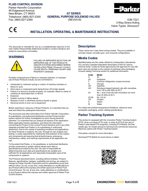
FLUID CONTROL DIVISION Parker Hannifin Corporation 95 Edgewood Avenue New Britain, CT 06051 G7 SERIES Telephone: (860) 827-2300 GENERAL PURPOSE SOLENOID VALVES Fax: (860) 827-2384 (REV0319)IOM 72213-Way Direct Acting Valve Types: 30xxxxxx7INSTALLATION, OPERATING, & MAINTENANCE INSTRUCTIONSThis document is intended for use as a complementary resource to the User Safety Responsibility Statements located in product literature and posted to /safety.WARNINGFAILURE OR IMPROPER SELECTION OR IMPROPER USE OF THE PRODUCTS AND/OR SYSTEMS DESCRIBED HEREIN OR RELATED ITEMS ("Products") COULD CAUSE DEATH, PERSONAL INJURY AND PROPERTY DAMAGE.Possible consequences of failure or improper selection, or improper use of these Products include, but are not limited to:∙ Unintended or mistimed cycling or motion of machine members orfailure to cycle∙ Work piece or component parts being thrown off at high speeds∙ Failure of a device to function properly, for example, failure to clamp orunclamp an associated item or device ∙ Explosion∙ Sudden moving or falling objects∙ Release of toxic or otherwise injurious liquids or gases ∙ Electrical shorts or burn out of equipmentBefore selecting or using any of these Products, it is important that you read and follow the subsequent instructions.This document and other information from Parker Hannifin Corporation, its subsidiaries, and authorized distributors provide Product and/or system options for further investigation by users having technicalexpertise. It is important that you analyze all aspects of the application, follow applicable industry standards, and follow the informationconcerning the Product in the current Product literature and in any other materials provided from Parker or its subsidiaries or authorizeddistributors. Due to the variety of operating conditions and applications for these Products or systems, the user, through its own analysis and testing, is solely responsible for making the final selection of the system and components and assuring that all performance, endurance,maintenance, safety, and warning requirements of the application are met.To the extent that Parker, or its subsidiaries, or authorized distributors provide component or system options based upon data or specifications provided by the user, the user is responsible for determining that such data and specifications are suitable andsufficient for all applications and reasonably foreseeable uses of the components or systems.The Products described herein, including without limitation, Product features, specifications, designs, availability and pricing, are subject to change by Parker Hannifin Corporation and its subsidiaries at any time without notice. Do not, at any time, make alterations or modifications to any Product without the express and written approval of Parker Fluid Control Division. Do not, at any time, make alterations or modifications to any Product without the express and written approval of Parker Fluid Control Division.DescriptionThese valves are 3-way direct acting models. They are available in normally closed, normally open, and universal configurations.Media CodesIdentified below are the codes utilized by Underwriters Laboratories (UL) and the Canadian Standards Association (CSA) for variouscommon fluids. Codes for fluids approved by the agencies for use with each valve are printed on the outside of individual valve packaging. Consult catalog Technical section for additional information.Code MediaA AirAC Acetylene F Common refrigerants, except ammonia G City gas GA GasolineHO Petroleum-based hydraulic oils with viscositiesfrom 125 to 400 SSU at 38°C02 No. 1 and 2 fuel oils with viscosities not morethan 40 SSU at 38°C02-06 No. 2-6 oil OX Oxygen S Steam W WaterFor media and ambient temperature limitations, reference valve nameplate, packaging, and/or catalog specifications.Parker Tracking SystemThis product is equipped with the innovative Parker Tracking System (PTS). Scan a product's PTS code, or enter its PTS ID into any of Parker's web-based PTS programs, including PTS Mobile, the free mobile app, for instant access to technical and commercial resources. Maximize uptime with Parker Tracking System.Visit /pts for more information. Download PTS Mobile for smart phone or tablet:IOM 7221 FLUID CONTROL DIVISIONPrinciples of Operation3-Way Normally Closed: .................................................................... 30xCxxxx7 De-Energized EnergizedDe-EnergizedPressure is connected to “PRS” and flow is blocked by the plunger seal pressing on the body orifice. Flow is permitted from “CYL” to “EXH”.EnergizedThe plunger lifts off the orifice allowing flow through valve from “PRS” to “CYL”. Flow from “CYL” to “EXH” is blocked by the plunger seal pressing on the stop orifice.3-Way Normally Closed with Manual Override: .............................. 31xCxxxx7Operation is per above except for the presence of a manual override feature. The 1/4-turn manual override is designed to be manually actuated by a flathead screwdriver. Regardless of electrical signal to the solenoid coil, flow is permitted from “PRS” to “CYL” when the stem slot is parallel with the ports. When the stem slot is perpendicular to the ports, flow is determined by the state of the solenoid coil.3-Way Normally Open: ...................................................................... 30xFxxxx7 De-Energized EnergizedDe-EnergizedPressure is connected to “PRS” and flow is allowed through the stop orifice to "CYL".EnergizedThe plunger lifts and flow is blocked by the plunger seal pressing on the stop orifice. Flow is permitted from “CYL” to “EXH”.3-Way Universal: ................................................................................ 30xUxxxx7 De-Energized EnergizedDe-EnergizedPressure may be connected to “NC” for Normally Closed operation, “NO” for Normally Open operation, “COM” for Diverting operation. The valve may also be plumbed for Mixing with outlet to COM.EnergizedFlow is permitted or blocked based on the operation type chosen above.InstallationCarefully read all installation, operating, and maintenance procedures prior to installing or servicing valves. Do not use valves as safety shut-off valves during installation or maintenance.WARNINGReturn system to atmospheric pressure beforeinstallation. Turn off electrical power before connecting valves to a power source. Valves to be installed in Hazardous Locations, must be equipped with compatible Hazardous Location solenoid coils. Verify nameplate data and solenoid coil part number before installation.Failure to comply could result in personal injury or death.Mounting Position and Piping:These valves are designed to be multi-poised and will perform properlywhen mounted in any position. For optimum longevity and performance, the valves should be mounted vertically upright to minimize wear and reduce the possibility of foreign matter accumulating inside the sleeve.Valves may be mounted directly on piping, by using the two (2) # 10-32 UNF threaded holes on the bottom of the valve, or with a compatible mounting bracket.If solenoid coil assembly orientation is inconvenient, uninstall nut (orsleeve adapter if present), washer, and nameplate and set them aside. Lift coil firmly to disengage upper and lower coil seals. Take care not to lose upper coil seal. With seals disengaged, rotate coil assembly to desired position. Reinstall components per the subsequent "Coil Replacement" section steps 5-6. Take care not to damage or misplace loose parts.CautionDo not use sleeve or enclosure as a lever when applying torque. Tightening torque for process connections should not exceed the following values for each port size:1/8" NPT: 100 in/lbs. 1/4" NPT: 175 in/lbs.IOM 7221FLUID CONTROL DIVISIONWARNINGWARNINGCautionWARNINGCautionRemove protective closures from the ports. Connect line pressure to "IN" port. Use of pipe thread tape or compound is permissible, but should be applied sparingly to external threads only. Loctite primer #764 and pipe sealant #567 are recommended when using stainless steel fittings with stainless steel valve bodies. Do not allow foreign particles, pipe thread tape, or compound to enter valves.Pressure and Temperature Limits:Application pressure and temperature parameters must conform to valve nameplate ratings. Prior to installation, reference valve labelling and packaging, and refer to the catalog to ensure application pressure and temperature requirements are met. Consult factory for applications requiring higher media or ambient temperatures.Standard valves are supplied with solenoid coils designed for continuous duty service (100% duty cycle).Normal free space must be provided for proper ventilation. When asolenoid coil is energized continuously for extended periods of time, the solenoid coil assembly will become hot. The coil is designed to operate permanently under these conditions. Any excessive heating will be indicated by smoking and/or odor of burning coil insulation.Electrical Connection and Voltage Limits:Electrical supply must conform to nameplate rating. Connect coil leads or terminals to the electrical circuit using standard electrical practices in compliance with local authorities and the National Electrical Code. The conduit solenoid coil and one-piece leaded solenoid coil contain a green “grounding” wire that must be secured to a proper groundlocation. Ensure applied voltage is within Parker-specified tolerances.Do not remove the grounding wire. Doing so could negate a proper ground path and leave the valve assembly unprotected or “electrically hot”. Failure to comply could result in personal injury or death.Prior to installation, reference valve labelling and packaging, and refer to catalog to ensure application electrical requirements are met.Media and Filtration:To ensure valve protection, install a suitable strainer or filter as close as possible to the valve inlet. Dirt or foreign material in the media may cause excessive leakage, wear, or in exceptional cases, malfunction.Prior to installation, reference valve labelling and packaging, and refer to the catalog to ensure application media requirements are met.Lubrication:Lubrication is not required although air line lubrication will substantially increase valve life.Ethylene propylene rubber (EPDM) valve materials must not be exposed to petroleum-based lubricants or other hydrocarbons.General MaintenanceDepending on service conditions, valve media, filtration, lubrication, periodic cleaning, and/or worn component replacement may be required.While in service, valves should be operated at least once per month to ensure proper operation.Periodic inspection of internal valve parts for damage or excessive wear is recommended.Thoroughly clean all parts if dirtied. If pressure vessel parts are worn or damaged, install a complete repair kit. If a replacement solenoid coil is required, install a complete coil kit.Repair Kits and Coil Kits :Scan a valve's unique PTS code, or enter its PTS ID into any of Parker's web-based PTS programs, including the free smart phone app, to order a repair kit and/or coil kit. Alternatively, refer to valve nameplate for the proper kit ordering numbers. Repair kits service the valve pressure vessel and replace relevant valve assembly seals. Coil kits replace the solenoid coil and, where relevant, its seals.Cleaning:All solenoid valves should be cleaned periodically. The time between cleanings will vary depending on the media and service conditions.In general, if voltage to the coil is correct, sluggish valve operation, excessive noise, or leakage indicates that cleaning is required. Inextreme cases, faulty valve operation will occur, and the valve may fail to open or close. Clean any strainers/ filters when cleaning valves.Do not expose plastic or elastomeric materials to any type ofcommercial cleaning fluid. Parts should be cleaned with a mild soap and water solution.Coil ReplacementPrior to servicing valve, depressurize valve, turn off electrical power supply, and disconnect solenoid coil from its power supply.Verify nameplate data and coil part number before installing replacement coil. Install only Hazardous Location replacement coils to valves equipped with Hazardous Location coils. Do not energize coils which are not properly installed to a compatible pressure vessel.Failure to comply could result in personal injury or death.If possible, remove valve from processconnections. If process connection is made to sleeve port, disconnect piping prior to disassembly. Component parts must bereplaced in the proper order and orientation. Take care not to damage seal(s) and/ ororifice(s). Valve contains loose parts. Take care not to misplace or damage them.1. Remove 11/16” hex sleeve adapter. Take care not to damage sleeve adapter seal.2. Uninstall washer, and nameplate. Place them in a secure area.3. To remove coil assembly, firmly lift it from pressure vessel until lower coil seal disengages. This requires significant force. Ensure the upper coil seal is not lost in the process.4. In the case of a multi-piece solenoid coil assembly, remove the solenoid coil from its yoke enclosure. Use new coil in place of old.5.Install all component parts in reverse order of disassembly,ensuring that any seals, washers, and/or nameplates, are properly re-installed to valve. Utilize replacement solenoid coil seals provided in coil kit, if replacing coil.6.Firmly press coil onto pressure vessel to properly engage lower coil seal. Proper lower coil seal engagement takes significant force and achievement of a proper seal will likely be audible.Ensure upper coil seal is installed. Tighten sleeve adapter with an input torque of 43-53 in-lbs.Pressure Vessel MaintenancePrior to servicing valve, depressurize valve, turn off electrical power supply, and disconnect solenoid coil from its power supply.Verify nameplate data and coil part number before installing replacement coil. Install only Hazardous Location replacement coils to valves equipped with Hazardous Location coils.Do not energize coils which are not properly installed to a compatible pressure vessel.Failure to comply could result in personal injury or death.If possible, remove valve from processconnections. If process connection is made to sleeve port, disconnect piping prior to disassembly.Component parts must be replaced in the proper order and orientation.Take care not to damage seal(s) and/ ororifice(s). Valve contains loose parts. Take care not to misplace or damage them.IOM 7221FLUID CONTROL DIVISIONWARNINGCautionValve Disassembly (Refer to subsequent "Figure 1"):1. Refer to steps 1-3 under preceding "Coil Replacement" section.2. These valves feature a 5/32” internal hex on top of sleeve assembly.Employ hex to loosen until finger tight.3. Hold the valve upside down. Fully loosen and remove the sleeve,its internal parts, and seal(s). Sleeve contains loose parts.4. Inspect componentry for wear. Take care not to damage seal(s)and/ or orifice(s).5. If parts are worn or damaged, install a complete repair kit andrefer to subsequent "Valve Assembly" instructions.Valve Assembly (Refer to subsequent "Figure 1"):1. If possible, and to avoid component damage, hold the valveupside down. Carefully hand tighten the sleeve assembly, ensuring all internal parts are installed in the reverse order of disassembly.2. With the valve positioned vertically and upright, employ 5/32”internal hex on top of sleeve and input torque of 130-150 in-lbs. to tighten sleeve assembly to body.3. Re-install solenoid coil assembly per preceding "CoilReplacement" steps 5-6.4. Refer to preceding "Installation" section for complete installationguidance.TroubleshootingPrior to servicing valve, depressurize valve, turn off electrical power supply, and disconnect solenoid coil from its power supply.Do not energize coils which are not installed to a proper pressure vessel.Failure to comply could result in personal injury or death.If possible, remove valve from processconnections. If process connection is made to sleeve port, disconnect piping prior to disassembly. Component parts must bereplaced in the proper order and orientation. Take care not to damage seal(s) and/ ororifice(s). Valve contains loose parts. Take care not to misplace or damage them.Valve Fails to Operate:1. Check electrical supply with voltmeter. Voltage must comply withnameplate rating. Consult catalog Technical section for additional information.2. If supply voltage is too low, locate and correct cause of lowvoltage. Voltage must exceed 85% of rated voltage.3. Check coil with ohmmeter for shorted or open coil. If open refer to"Valve Coil Burn-Out".4. Ensure pressure complies with label rating. If conforming, refer to"Valve is Sluggish or Inoperative".External Leakage (At sleeve flange to body interface, or sleeve adapter):1. Check that sleeve is torqued per preceding "Pressure VesselMaintenance “section, subsection "Valve Assembly".2. Check that sleeve adapter is torqued per preceding "PressureVessel Maintenance “section, subsection "Valve Assembly". 3. If leakage persists at flange, remove sleeve per preceding"Pressure Vessel Maintenance" section, subsection "Valve Disassembly" and inspect flange seal. If damaged or worn, service valve with repair kit per preceding "Pressure Vessel Maintenance" section.4. If leakage persists at sleeve adapter, consult factory forreplacement item ordering number.Internal Leakage (Leakage through valve): 1. Disassemble valve as per preceding "Pressure VesselMaintenance" section, subsection "Valve Disassembly". Clean out extraneous matter. Clean parts per preceding "Maintenance" section, subsection “Cleaning".2. Examine plunger, plunger seal, and spring(s) for damage. Ifdamaged, service valve with repair kit.3. Inspect orifice in the body for damage or wear. Damaged orifice(s)may require valve replacement.4. Under normal operation, and with coil de-energized, check powerat coil wires. Power should be off. If power is present, correct faulty contacts or wiring.Figure 1The representative exploded view below identifies valve components included in repair kits and coil kits, respectively. It is intended to serve as a representative visual aid only. Specific valve models may deviate from this representation.Key:Included in coil kit (replace solenoid coil and its seals)Included in repair kit (service pressure vessel, replace coil seals)Sleeve Adapter Assy., 11/16” (43-53 in-lbs.)WasherUpper Coil Seal Solenoid Coil Assy.Valve Coil Burn-Out:1. Continuous high voltage greater than 10% of rated voltage couldresult in solenoid coil failure. Validate voltage and correct ifnecessary. Consult catalog Technical section valve voltage range. 2. Disassemble valve as per preceding "Pressure VesselMaintenance" section, subsection "Valve Disassembly". Clean out extraneous matter. The plunger must be free to move without binding.3. If valve has been exposed to excessive ambient temperature,ventilate or isolate area from elevated temperatures. May require valve relocation to lower temperature area.4. Order coil kit to replace coil per preceding "Coil Replacement"section.Valve is Sluggish or Inoperative (Electrical, pressure conform):Lower Coil SealSleeve Assy.(130-150 in-lbs.)Plunger Assy.1. Disassemble valve as per preceding "Pressure VesselMaintenance" section, subsection "Valve Disassembly". Clean out extraneous matter. The plunger and spring assembly must be free to move without binding.2. The plunger spring must not be damaged. If damaged, servicevalve with repair kit.Flange Seal。
Honeywell BW Solo - 无线气体检测器说明文档说明书
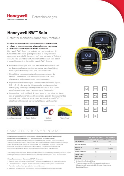
Detección de gasNOETOSO2H2NH3Cl2PH3HCNNO2C l O2H2S O2O3COFácil de manejar Fácil de leer Fácil demantenerFácil de verC A R AC T E RÍS T I C A S Y V E N TA J A SPara optimizar tiempos, incluyendo visibilidad remota de las alarmas,elija la versión inalámbrica. Y gestiónelo con su smartphone.Empareje el Honeywell BW™ Solo inalámbrico con nuestra aplicación móvil"Safety Communicator" y las lecturas del detector se enviarán instantáneamenteal software de supervisión en tiempo real de Honeywell. Acceda a él desdecualquier dispositivo mediante una conexión a Internet y obtenga unavisibilidad remota de la ubicación y la seguridad de los trabajadores.También puede utilizar el Honeywell BW™ Solo inalámbrico para compartir los datossobre gas con el software de escritorio; no requiere ninguna base de conexión.Otras funciones de Honeywell BW™ Solo son:• Opción para activar el IntelliFlash™ o la luz parpadeante de incumplimiento• La capacidad de asignar detectores a los trabajadores y a las ubicaciones• Pantalla fácil de leer que admite varios idiomas• Registro de datos con una lectura evolutiva de valor límite de 24 horasEl detector monogas de última generación que le ayudaa reducir el coste, garantizar el cumplimiento normativoy saber que sus trabajadores están protegidos.Honeywell BW™ Solo tiene todo lo que espera, además defunciones adicionales que lograrán que el cumplimientonormativo sea más fácil y más económico que nunca. Todo esocon una vida útil fiable, un funcionamiento con un solo botóny un perfil pequeño y ligero. Honeywell BW™ Solo es:• El detector monogas más fácil de mantener, sin necesidadde desmontarlo para sustituir sensores, baterías y filtros.Esto significa una larga vida y un coste reducido.• Complételo con una amplia selección de opciones desensor. Contará con una detección exhaustiva, tantosi supervisa peligros comunes como inusuales.CO, H2S y O2. Lo que significa una alta precisión, costesmás bajos y un tiempo de respuesta del sensor más rápidopara los gases que supervise con mayor frecuencia.• Compatible con IntelliDoX. Ahorre tiempo y centralice los datoscon pruebas funcionales, calibraciones y gestión de instrumentosautomáticas. Utilice las estaciones automáticas IntelliDoX conel software Honeywell Safety Suite Device Configurator.Honeywell BW™ SoloDetector monogas duradero y rentableBW™ SOLO Y BW™ SOLOWIRELESS DE HONEYWELLBW™ SOLO LITE*DE HONEYWELLTIPO DE SENSOR Serie 1**Serie 4REGISTRO DE DATOS Sí–REGISTRO DEEVENTOS50 eventos 5 eventosIDIOMAS ADMITIDOS115ASIGNACIÓN DETRABAJADOR YUBICACIÓNSí–* No disponible en América del Norte.** Póngase en contacto con el Servicio de atención al cliente o conel departamento de ventas regional de Honeywell Pregunte por ladisponibilidad al gestor.Honeywell BW™ SoloEspecificaciones técnicasDEBIDO A LA INVESTIGACIÓN CONTINUA Y A LAS MEJORAS CONSTANTES QUE SE APLICAN A LOS PRODUCTOS, LAS ESPECIFICACIONES ESTÁN SUJETAS A CAMBIOS SIN PREVIO AVISO.Datasheet_Honeywell BW Solo_DS110218-01_ES-ES | 11/18© 2018 Honeywell International Inc.* Solamente el Honeywell BW™ Solo Lite (no disponible en América del Norte).SISTEMA DE ACOPLAMIENTO INTELLIDOX IntelliDoX combina los módulos de acoplamiento inteligentes con nuestro sistema de gestión deinstrumentos para proporcionar pruebas automatizadasy facilitar la conservación de registros.Gestión de dispositivos con Honeywell Safety Suite/Safety SuitePara más información Honeywell HPPECra. 11a #98-50, Bogotá, ColombiaTamaulipas 141, 1° Piso, CDMX, México 06140Soporte al Cliente:e-mail:****************************。
上海科旗自动化仪表 YB04测量显示控制仪 使用说明

YB04测量显示控制仪使用说明书一、主要特点:1、适用于配压力、位移、称重、拉压力等各种传感器对相应物理量的测量控制2、开放式仪表参数设定3、支持多机网络通讯(需订货时说明),配专用软件,可方便地实现仪表与上位机的联网测控管理。
在一台计算机上同时显示、打印1~8台仪表波形及数据。
4、设定参数密码锁定,断电后永久保存。
二、技术参数输入信号模拟量0~20mV,0~5V,0~±5V,0~10V,4~20mA,0~10KΩ测量范围-1999~9999字采样速度2次/秒测量精度0.2%FS±1字或0.5%FS±1字分辨率1、0.1、0.001字显示方式.-1999~9999LED测量值显示.-1999~9999设定值显示输出信号馈电输出DC24V,负载能力≤30mA,称重传感器馈电输出DC5V或DC9V控制方式可选择1~4限控制或1~4组带差式控制,LED指示。
控制方式为继电器ON/OFF带回差/带差(用户可自由设定)控制精度±1字报警方式可选择1~4限报警,LED指示。
报警方式为继电器ON/OFF带回差(用户自由设定)报警精度±1字参数设定面板轻触式按键数字设定参数设定值断电后永久保存参数设定值密码锁定保护方式继电器输出状态LED指示输入超/欠量程指示电源欠压自动复位工作异常自动复位(Watch Dog)联机通讯通讯协议为二线制、三线制或四线制,也可由用户特殊要求,波特率300~9600bps可由仪表内部参数自由设定,接口和主机采用光电隔离,提高系统的可靠性及数据的安全。
采用RS485方式时,通讯距离可达1公里。
配专用软件,可实现多台仪表与一台或多台微机进行联机通讯,构成各种数据采集及控制系统。
系统采用主从通讯方式,即每次通讯都须由上位机先向仪表发送命令,仪表再做相应的回答。
上位机可随时调用仪表的现场数据,并可对仪表参数进行设定及模拟仪表按键。
使用环境环境温度0~50℃相对湿度≤85%RH避免强腐蚀气体供电电压AC220V±10%50Hz(或DC24V,需订货时说明)功耗≤5W结构标准卡入式三、仪表面板定义:(一)160*80仪表面板定义:(二)96*48仪表面板定义:包括单排四位LED显示测量(PV)和设定值(SV)四、操作方式1.正确的接线仪表卡入表盘后,请参照仪表随机接线图接妥输入、输出信号线及电源线,并请确认无误。
上海柯普乐自动化仪表有限公司磁致伸缩液位变送器操作说明书

上海柯普乐自动化仪表有限公司Shanghai KSR-KUEBLER Automation Instrument Co., Ltd.V2.0.FLM(CN/EN)/05.2022磁致伸缩液位变送器Magnetostrictive level transmitter安装和操作说明书Mounting and operating instructions2014L300-31Q31/0117000277C002-2022目 录工作原理 1 应用领域 2 技术指标 2 结构安装 2 电气连接 5 操作规程 6 模拟输出18 数字通讯18 失效分析及支持22 维修及维护23 防爆说明23 储存23 质量保证23 产品附件23 ATEX Ex d说明25 浪涌保护器说明30 SIL安全手册31工作原理 一根磁致伸缩线穿过导管,顶部电路板周期发射的大电流脉冲沿磁致伸缩线传播,产生环形电磁场。
脉冲发射的同时开始记录时间。
浮球漂浮在液面上, 内置磁钢。
两个磁场交叠处,在磁致伸缩线上产生扭应力波,以与材料相关的特定速度,沿着磁致伸缩线向上下两个方向传播。
其中向下传播的扭力波到达传感器底部后发生反射再向上传播。
两个扭应力波传到顶部后被压电晶体转换成电信号,两个传播时间也被捕捉记录。
通过计算可得出液面和界面的位置,转换后输出电信号。
图2. 产品示意图图1. 磁致伸缩效应图FFG-P 系列FFG-BP 系列电流脉压电晶扭应力磁致伸缩线扭应力浮球内置磁浮球磁场电流磁场应用领域 MAGNODUL磁致伸缩液位计精度很高,采用浮力和磁致伸缩原理来连续测量液位,FFG-P 型变送器安装于罐体的顶部或者底部,FFG-BP 型变送器配合磁性翻柱式液位计使用。
经过认证可用于存在爆炸性气体的危险环境。
特性:·传感器导管完全密封; ·无磨损;·依靠磁性来检测液位;·振动和小的冲击影响不明显; ·接线盒防护等级:IP66 / IP67; ·高精度; ·高分辨率;·液面变化响应快;·电压下降后测量值也可快速读取; ·直接、线性的测量液位;·可根据给定罐体的形状将液位高度转换成容积;·内部传感器由金属外管保护,所以适合用于腐蚀和有毒的介质,也可用于食品饮料行业;·线性模拟液位量程,输出4-20 mA 电流信号,可用于控制和显示设备,兼容数字 HART ®界面使得单一回路上带多个变送器成为可能(多站式)。
浅谈科威特MAGWA区块浅层气井控技术措施
浅谈科威特MAGWA区块浅层气井控技术措施作者:卜伟梁来源:《科学与财富》2020年第19期摘要:浅层气通常埋藏浅,气体上串速度快,井控难度大。
一旦井喷,难控制,容易造成着火、人员伤亡、油气井报废、污染环境恶性事故等。
科威特MAGWA区块地层复杂,泥岩、砂岩、页岩夹杂,使用8-1/2”领眼钻穿表层,减少气层裸露面积并采用分流器进行正确的放喷分流及压井可有效地把井控的各种风险减到最小。
实践证明采取的预防浅层气井控技术措施行之有效,具有较强的可操作性。
关键词:浅层气;领眼;井控技术一、浅气层井喷的主要原因和危害(一)浅气层井喷主要原因:(1)起钻抽吸、钻速太快、起钻补灌钻井液不及时。
(2)地层压力异常,一旦井喷,能使气体迅速上串,层位浅使报警信号反应时间短,可燃性气体可能在几乎没有报警的情况下就到达地面,容易让人措手不及。
(3)起钻时尤其危险,可能使井筒内所有钻井液喷出。
(4)体积小,难以预测,经常突然出现。
(5)浅气层井喷很难控制是因为地层压力与地层破裂压力相差很小,表层一般是薄弱地层,容易憋裂。
(6)钻浅井段时井口的控制装置配置不到位。
(二)浅气层的危害:(1)浅气层井喷容易憋裂地层,造成井漏或井喷起火、人员伤亡、油气井报废、烧毁井架。
(2)井喷塌陷时,钻机与平台可能下沉,设备报废。
(3)喷出的气体污染环境。
二、井控技术管理(一)人员培训在每口井开钻之前进行技术交底会。
技术交底会要求所有钻井队人员和第三方服务人员必须参加会议。
技术交底会讨论的主要话题是:讲解钻井程序风险点、潜在的钻井危害(包括对检测/控制浅层气的讨论)、钻开浅气层技术方案。
对班组人员进行井控知识培训,督促落实巡回检查制度及岗位值班制度。
组织井控、硫化氢实战应急演练,让班组人员熟练掌握应急反应程序,做到紧急情况忙而不乱,在钻穿套管附件前,针对井队每个人员都要进行导流器的训练作业,以确保所有人员都了解在处理浅层气气流时他们各自的责任。
科瑞凯ZW9T系列三相智能电量仪表说明书

该系列仪表可广泛应用于控制系统、SCADA系统和能源管理系统、变电站自动化、配电网自动化、小区电力监控、工业自动化、智能建筑、智能型配电盘、开关柜中;有安装方便、接线简单、维护方便、工程量小、现场可编程设置输入参数的特点。
警告 如果不按说明书操作会发生意外,而且会导致产品毁坏。
ZW9T系列三相智能电量仪表说明书⊙测量项目:电压/电流/有功功率/无功功率/频率/功率因数/等,共28个电参数;⊙真有效值测量;⊙两路开关量输入和两路开关量输出,输入/输出全隔离;⊙具有遥信、遥控功能;⊙具有可编程变送输出功能,可对电压/电流/有功功率/无功功率/频率/功率因数变送输出;⊙具有RS485通信接口,采用Modbus RTU通信协议;⊙具有二路电能脉冲输出,二路可编程报警输出;⊙对有功电度/无功电度有掉电保护功能;⊙可参考的双向有功电度/无功电度记录;⊙具有8时段,4种费率统计功能;⊙32条事件记录功能;⊙320×240像素彩色中英文液晶显示;特点一、仪表型号三、主要技术参数输入测量范围: B:5A×220V D:其它输入:30:三相三线或三相四线输入 38:三相三线或三相四线输入带通讯 报警功能:C:表示两路报警 A:表示无报警输出功能:R:表示无变送输出 D:表示变送输出 DC 4~20mA 2D:两路变送输出 DC:4~20mA ZW系列三相电量表□□□□-ZW9T 二、型号说明外形尺寸(mm): 9:96W×96H×100L L:表示段码LCD显示 T:表示TFT液晶显示 无:数码管 无RS485 无RS485 无RS485无无 无 无 无 无一路有功报警方式脉冲输出功能变送功能 通讯功能 开关量输入 复费率ZW9T-A30B ZW9T-A38B ZW9T-RC30B ZW9T-RC38B ZW9T-2DC30B ZW9T-2DC38B 型 号22222路无无RS485 无RS485 无RS485无无 无 无 无 无ZW9T-A30BF ZW9T-A38BF ZW9T-RC30BF ZW9T-RC38BF ZW9T-2DC30BF ZW9T-2DC38BF22222路有三相四线、三相三线3*220/380V 持续:1.2倍<1VA (每相)≥300K ΩRMS测量 精度0.5%F.S 5A(经互感器接入)持续:1.2倍 瞬时:10倍/10S <0.4VA (每相)<20m Ω网络参比电压电压过负荷电压功耗 电压阻抗 电压精度 额定电流电流过负荷电流功耗 电流阻抗2×4~20mA 2×4~20mA 2×4~20mA 2×4~20mA一路无功一路有功一路无功□F:复费率四、面板说明五、菜单修改说明查看测量值及仪表工作状态说明:复费率(使能情况下)等界面切换显示。
Kestrel 5700运动弹道应用气象仪说明书

Kestre全面剖析图温度传感器电源键 选项/退出键KesKestrel 5700运动弹道应用气象仪可更换叶轮仪器型号左右键上下键数据抓取背光键Kestrel 5700Link 版本Kestrel 5700 运动弹道应用弹道应用案例Kestrel 5700 运动弹道应用1、Kestrel 57002、保护袋3、绳带道应用气象仪Link版本道应用气象仪的配置:4、 一节AA 电池(平均寿5、 COC 证书6、 使用说明书Kestrel 5700 运动弹道应用1、 kestrel 5700 Link 2、 风向标组合 3、 保护布包 4、 绳带5、 1节AA 电池(平均寿6、 COC 证书7、 使用说明书Kestrel 5700 运动弹道应用Kestrel 5700运动弹道应用采用弹道应用库的自定义阻力移、科里奥利力和自由落体分卡片和扩展的弹道数据表,以及和Kestrel 5500一样的完整的环大气压和高度。
Kestrel 5系列产品提供了色背光,高强度聚碳酸酯玻璃片应用软件。
和所有的Kestrel 损坏,所以它可以陪着你去你除了测量当前的环境条件有的数据可以通过Link 可选配Kestrel LiNK Dongle 或USB 数据售)。
技术参数:物理显示时间和性能风速风向平均寿命400小时)道应用气象仪Link 版本配置:版本平均寿命400小时) 道应用气象仪道应用气象仪提供远程射击的预测,甚至超音速和亚音义阻力模型,根据精确的测量子弹的阻力资料和修正空落体分解从而达到精确的命中更为远程的目标。
扩展的以及存储16支枪和子弹资料和5个枪靶的保存资料整的环境测量、存储和绘图功能,包括风速、风向提供了一个大的、高分辨率和用眼比较轻松的显示屏玻璃片,一节AA 电池供电和可选的LiNK iOS 和 Andr rel 产品一样,Kestrel 5700防滴水、防尘、防水和能在你去你敢去的地方旅行。
还有随身携带袋让你跟便于携境条件外,Kestrel 5700可以跟踪和记录超过10000组带可选配件和Link APP 应用程序传输到iOS/Android 设备数据传输线缆两者其中之一上传到Windows / Mac 尺寸 127mm×45mm×28mm 重量 102g外壳颜色 黑色/橄榄绿/棕褐色显示类型 点矩阵LCD ,场致(EL )发光背光 显示器更新 1秒数据采集2秒到12小时之间,可调;图表可显示动或自动采集数据,数据可上传至电脑。
上海科旗自动化仪表压力变送器 说明书
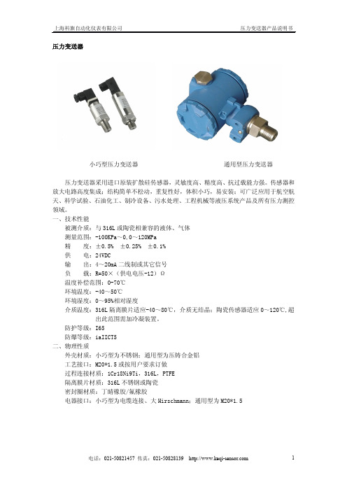
压力变送器小巧型压力变送器通用型压力变送器压力变送器采用进口原装扩散硅传感器,灵敏度高、精度高、抗过载能力强。
传感器和放大电路高度集成;结构简单不松动,重复性好,体积小巧,易安装;可广泛应用于航空航天、科学试验、石油化工、制冷设备、污水处理、工程机械等液压系统产品及所有压力测控领域。
一、技术性能被测介质:与316L或陶瓷相兼容的液体、气体测量范围:-100KPa~0,0~120MPa精度:±0.5%±0.25%±0.1%供电:24VDC输出:4~20mA二线制或其它信号负载:R=50×(供电电压-12)Ω温度补偿范围:0-70℃环境温度:-40~50℃环境湿度:0~95%相对湿度介质温度:316L隔离膜片适应-40~80℃,介质无结晶;陶瓷传感器适应0~120℃,超出此范围需加冷凝装置。
防护等级:I65防爆等级:iaIICT5二、物理性质外壳材质:小巧型为不锈钢;通用型为压铸合金铝工艺接口:M20*1.5或按用户要求订做过程连接材质:1Cr18Ni9Ti,316L,PTFE隔离膜片材质:316L不锈钢或陶瓷密封圈材质:丁睛橡胶/氟橡胶电器接口:小巧型为电缆连接、大Hirschmann;通用型为M20*1.5三、电气连接图1)小巧型2)通用型四、外型尺寸例:SPB-G-100KPa-1-0.2-1H-2表示小巧型压力变送器,表压,量程0~1bar,4~20mADC输出,0.2级,M20×1.5接口,Hirschminn连接器,耐腐蚀性。
SMF5000型压力变送器选用进口压力芯片,敏感元件采用扩散或离子注入等工艺形成电阻并连接成惠斯通电桥,用微机械加工技术在电桥下形成压力敏感膜片。
当压力作用在膜片上时,电阻值发生变化并且产生一个与作用压力成正比的线性化输出信号。
我们在惠斯通电桥上加上直流电源,就会产生一个直流电压信号的输出。
经过二次转换线路,实现两线制4~20MA输出。
上海科旗自动化仪表 涡轮流量计 说明书

涡轮流量计一、概述LW系列涡轮流量计具有结构简单、轻巧、精度高、复现性好、反应灵敏,安装维护使用方便等特点,广泛用于石油、化工、冶金、供水、造纸等行业,是流量计量和节能的理想仪表。
适用于在工作温度下粘度小于5×10⁻⁶m2/s的介质,对于粘度大于5×10-6m2/s的液体,要对传感器进行实液标定后使用。
此产品有测液体、气体两种系列。
二、产品特点*压力损失小,叶轮具有防腐功能;*采用先进的超低功耗单片微机技术,整机功能强、功耗低、性能优越。
*具有非线性精度补偿功能的智能流量显示器。
修正公式精度优于±0.02%*仪表系数可由按键在线设置,并可显示在LCD屏上,LCD屏直观清晰,可靠性强*采用EEPROM对累积流量、仪表系数掉电保护,保护时间大于10年*采用高性能MCU中央处理器,完成数据采集处理显示输出、累积流量瞬时流量同屏显示方便的人机界面实现,以标准485形式进行数据传输。
*采用全硬质合金(碳化钨)屏蔽式悬臂梁结构轴承,集转动轴承与压力轴承于一体,大大提高了轴承寿命,并可在有少量泥沙与污物的介质中工作。
*采用1Cr18Ni9Ti全不锈钢结构,(涡轮采用2Cr13)防腐性能好。
*容易维修,有自整流的结构,小型轻巧,结构简单,可在短时间内将其组合拆开,内部清洗简单。
*有较强抗磁干扰和振动能力、性能可靠、寿命长*下限流速低,测量范围宽*现场显示型液晶屏显示清晰直观,功耗低,3V锂电池供电可连续运行5年以上*耐腐蚀,适用于酸碱溶液三、技术参数公称口径管道式:DN2~DN200插入式:DN100~DN2000精度等级管道式:±0.5级,±1.0级插入式:±1.5级、±2.5级环境温度-20℃~50℃介质温度测量液体:-20℃~120℃测量气体:-20℃~80℃大气压力86KPa~106KPa公称压力 1.6Mpa 、2.5Mpa 、6.3Mpa 、25Mpa 防爆等级ExdIIBT4连接方式螺纹连接、法兰夹装、法兰连接、插入式等直管段要求气体:上游直管段应≥10DN,下游直管段应≥5DN 液体:上游直管段应≥20DN,下游直管段应≥5DN插入式:上游直管段应≥20DS,下游直管段应≥7DS(DS 为管道实测内径)显示方式(1)远传显示:脉冲输出、电流输出(配显示仪表)(2)现场显示:8位LCD 显示累积流量,单位(m 3)4位LCD 显示瞬时流量,单位(m 3/h)、电池电量、频率、流速(3)温度压力补偿型:A、显示标准瞬时流量及标准累计流量B、显示当前压力、温度、电池电压输出功能(1)脉冲输出,p-p 值由供电电源确定(2)4~20mA 两线制电流输出(3)单位体积脉冲输出及传感器原始脉冲输出(4)带有RS485通迅接口供电电源(1)DC5~24V(2)标准型3V 锂电池安装于仪表内部可连续使用八年以上(3)温压补偿型3V 锂电池安装于仪表内部可连续使用四年以上传输距离传感器至显示仪距离可达500m四、选型提示选购气体智能型涡轮流量计需详细确定以下参数:管道管径,测量介质,工作温度,压力(工作状态或标准状态),安装方式(管道式或插入式),供电电源(12V、24V 或电池供电),输出方式(4-20mA、脉冲输出或485通迅),最大流量(工作状态或标准状态),需不需防爆,法兰连接型要不要带配对法兰。
EKI系列紧凑型工业以太网交换机
领 域 ,对 高压 开 关 柜 、开 关刀 闸 、电 缆 接 头 、变压 器 等 高 压 电力 设 备 和 自
本产 品用 于保 护 2V 供 电 的 二 4 线制 变 送 器 电流 环路 。由陶 瓷 气体 放
器 (S S C)是 专 门针 对 石 油 、 石 化 、
动化生产线设备因绝缘老化、接触不 良、工作异常或环境变化等引起 的温
度 变 化进 行 实 时监 测 和 报警 ,便 于 及 时 发现 故 障 ,排 除 安全 隐患 ,保 障 设
备 正常 运 行 。
炼油、储运和配送领域设计研发的。 该解 决方 案是 首个 符合 欧盟计 量器
具 指 令 ( D)的 集 成 添加 剂 和 调 和 MI 控制 器 。它 独 特 的 调和 算 法 可 以帮 助 企 业 达 到 高 精确 度 的配 比 ,从 而 减 少
远 程 测 试 。( 京 科 尔 康 安 全 设 备 制 北 造有限公司 )
读者服务卡编号 0 4 4[ ]
刷 平 面 型 使 其 可 用 于 多种 不 同应 用 。 P T多 样 化 配 置 也 可 与 客 户 的 多样 化 F
需 求 相 匹配 。
P T压 力 变 送 器 的特 点 在 于 其 精 F
S P 1变送 器 用 集 成 防 雷模 块 额 T. 定 工 作 电压 :2 V,响 应 时 间 :< n , 4 Is
最 大 放 电电 流 : 5A ( k 到接 地 壳 体 ) ,
少高达 2 %的校对 时间。一个校准 向 5
导可 以 自动 捕 捉 每 一个 设备 ,包 括 时
最大瞬态 电压:10 C,环路插入 0VD
X adI 型 气 体 探 测 仪 的 作 用 g r. R 包 括 监 测 泵 房 内贮 罐 、管 道 和 阀 门的 滴 漏 。它 能 够 在 气 体 浓 度 达 到 可 燃 标
wika是哪个国家的品牌

wika是哪个国家的品牌wika是哪个国家的品牌:WIKA公司是德国乃至世界上最大的生产压力和温度测量仪表及设备的专业厂家之一,总部位于德国法兰克福克林根堡,子公司遍布全球七十多个国家。
适用于多种行业的测温,测压.精度高,性能稳定.系列产品:全不锈钢压力表、隔膜压力表、压力变送器、双金属温度计、气体膨胀式温度计、温度变送器等等,可满足各种环境下的测量要求。
压力产品电子式压力测量仪表WIKA提供全面的电子式压力测量仪表。
用于测量一般压力,绝压和差压的压力传感器,压力开关,压力变送器,测量范围从0...0.6mbar至0...10,000bar,这些仪表可以输出标准的电流或电压信号,并且针对不同的现场总线应用领域提供相应的接口或协议。
不论陶瓷厚应变片,金属薄应变片或压敏电阻,WIKA是目前全球唯一的可以完全自己生产领先的精密传感器的制造商。
机械式压力测量仪表带有波登管,膜片或膜盒测量系统的一般压力表,绝大压表和差压表已经接受无数次检验。
这些仪表的测量范围从0...2.5mbar至0...7000bar,精度等级可达0.1%并且可以配备机械的或电子的附件,也可以结合不同结构的化学密封来实现不同的测量目的。
化学密封WIKA化学密封的实践性已在世界范围内被肯定。
通过化学密封的不同设计与特殊材料相结合,使压力表,压力变送器和压力开关可以实现特殊环境下的测量。
借助于化学密封,测量仪表可以应用于极端的温度环境,测量腐蚀性,不均匀,磨蚀性,粘稠性,有毒性介质。
另外,化学密封实现了过程测量仪表的卫生型连接。
温度产品:电子式温度测量仪表产品范围包括热电偶,电阻式温度计,模拟及数字的温度变送器,数字显示仪,控制仪和校验仪。
温度测量范围从-200°C至+1800°C。
机械式温度测量仪表WIKA的机械温度测量仪表利用双金属变形或气体膨胀的工作原理,温度测量范围从-200°C至+700°C。
- 1、下载文档前请自行甄别文档内容的完整性,平台不提供额外的编辑、内容补充、找答案等附加服务。
- 2、"仅部分预览"的文档,不可在线预览部分如存在完整性等问题,可反馈申请退款(可完整预览的文档不适用该条件!)。
- 3、如文档侵犯您的权益,请联系客服反馈,我们会尽快为您处理(人工客服工作时间:9:00-18:30)。
柯威特Kewait创建于1980年,如今的柯威特kewait在中国已经成为众多重点国家级项目建设的合作伙伴。
目前,公司通过位于上海的总部及下辖的12个办事处,竭诚就近为用户提供产品销售、技术咨询、标定、现场调试、人员培训、备品备件等各项服务。
柯威特Kewait致力于提供广泛用于各种工业领域的测量的自动化仪表,注重于改善和提高化工、石油和天然气、电力与能源、水和污水处理、食品和饮料、生命科学、基础原材料和冶金、纸浆及造纸、造船和海上运输等领域的过程效益。
柯威特Kewait是工业过程测量及自动化领域的顶级产品、解决方案和服务供应商。
在广泛的工业领域中,kewait可在流量、液位、密度、压力、分析、温度、记录和数字通信方面提供全面的过程解决方案,并在经济效率、安全性和环保方面对过程进行优化。
柯威特Kewait提供专业用于过程自动化行业的仪表、系统和服务,涉及物位、流量、压力、温度、分析测量与数据采集。
各行业优化解决方案
我们支持您应对严酷的环境挑战
过去60年来,柯威特kewait一直为过程工业提供高品质的仪表,为过程测量和自动化提供创新的系统。
随着应用经验的不断积累,kewait开发了大量的产品和服务,kewait的产品和服务不仅满足您的应用需求,而且超
出您的期望。
无论您需要的是一台仪表还是一套完整的自动化系统,kewait 都是您的不二之选。
全球过程自动化领域专家
柯威特Kewait是提供工业过程控制测量仪表、服务与解决方案的全球领导者。
从经济效益、安全与环境影响方面出发,Kewait提供流量、物位、压力、分析、温度、数据采集与通讯、流程优化的过程自动化解决方案。
Kewait 的客户来自于一系列不同的行业,包括化工、石化、食品与饮料、石油与天然气、水和污水、电力与能源,以及生命科学等等。
优势
∙Kewait始于1980——全球知名的仪表领域专家
∙Kewait全球直属员工12万——拥有强大可靠的专业团队
∙Kewait着手于未来科学——一直着眼未来的远见卓识
∙Kewait拥有数百个专利——具有创新权威的研发能力。
