AOC T2369M T2369Z 维修手册
冠捷I2369V液晶显示器维修手册
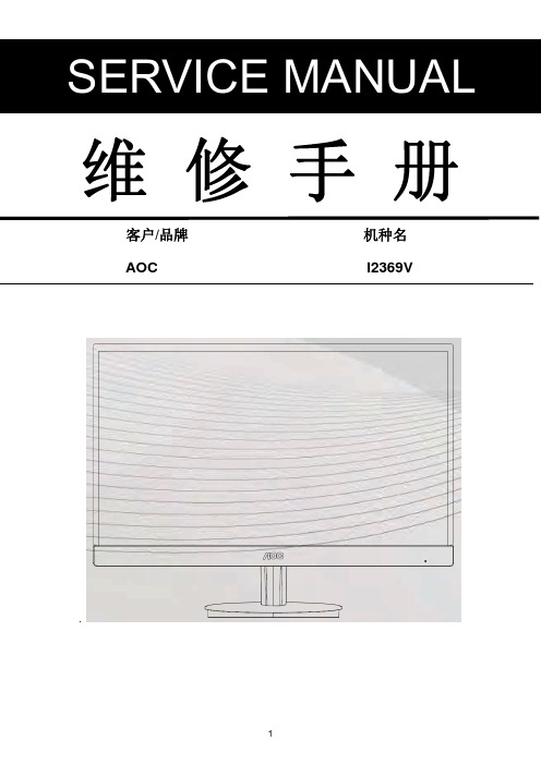
维修手册客户/品牌机种名AOC I2369V变更说明版本发布日期变更说明对外机种名对内机种名A00 JAN,28,2013Initial Release I2369V TDCJN27YFVA2HNF.LF A01 FEB,06,201,2 Add new model I2369V/WW TDCJN27YFVA3HNF.LF目录1. 技术规格 -------------------------------------------------------------------------------------------------------------- 4 1.1 一般规格 --------------------------------------------------------------------------------------------------------- 4 1.2 工厂预设模式 --------------------------------------------------------------------------------------------------- 52. 操作说明 -------------------------------------------------------------------------------------------------------------- 62.1控制面板--------------------------------------------------------------------------------------------------------- 62.2接口说明--------------------------------------------------------------------------------------------------------- 7 2.3 OSD菜单调整 ------------------------------------------------------------------------------------------------- 83. 工厂模式调整 -------------------------------------------------------------------------------------------------------- 234. 电气方框图 ----------------------------------------------------------------------------------------------------------- 245. 线路图 ----------------------------------------------------------------------------------------------------------------- 255.1主板--------------------------------------------------------------------------------------------------------------- 255.2按键板------------------------------------------------------------------------------------------------------------ 305.3电源板------------------------------------------------------------------------------------------------------------ 316. ISP和DDC烧录SOP --------------------------------------------------------------------------------------------- 347. 故障处理流程 -------------------------------------------------------------------------------------------------------- 477.1主板--------------------------------------------------------------------------------------------------------------- 477.2按键板------------------------------------------------------------------------------------------------------------ 518.主要IC管脚及内部框图 -------------------------------------------------------------------------------------- 529. 附带软件使用SOP--------------------------------------------------------------------------------------------- 569.1分屏软件SOP -------------------------------------------------------------------------------------------------- 56 9.2 e-Saver SOP --------------------------------------------------------------------------------------------------- 57 9.3 i-Menu SOP ---------------------------------------------------------------------------------------------------- 5810. 料件清单 ------------------------------------------------------------------------------------------------------------ 591、技术规格1.1 一般规格1.2 工厂预设模式2. 操作说明2.1控制面板2.2接头引脚分配管脚号信号电缆的 15 针一端管脚号信号电缆的 15 针一端1 视频 - 红色9 +5V2 视频 - 绿色10 接地3 视频 - 蓝色11 N.C.4 N.C. 12 DDC- 串行数据5 检测电缆13 H- 同步6 GND-R 14 V- 同步7 GND-G 15 DDC- 串行时钟8 GND-B管脚号信号名称管脚号信号名称管脚号信号名称1 TMDS 数据 2- 9 TMDS 数据 1- 17 TMDS 数据 0-2 TMDS 数据 2+ 10 TMDS 数据 1+ 18 TMDS 数据 0+3 TMDS 数据 2/4 屏蔽11 TMDS 数据 1/3 屏蔽19 TMDS 数据 0/5 屏蔽4 TMDS 数据 4- 12 TMDS 数据 3- 20 TMDS 数据 5-5 TMDS 数据 4+ 13 TMDS 数据 3+ 21 TMDS 数据 5+6 DDC 时钟14 +5V 电源22 TMDS 时钟屏蔽7 DDC 数据15 接地(对于 +5V )23 TMDS 时钟 +8 N.C. 16 热插拔检测24 TMDS 时钟 -2.3 OSD 调节明亮度图象设置色温窗口增亮OSD 设置其它退出3 工厂模式调整进入工厂模式方法:关机状态下,长按左右两个方向键后做开机动作,待按键指示灯亮后松手,从OSD菜单后左上角“F”进入工厂。
液晶显示器实用检修指导书
为什么如此清晰的原因。LCD也不必关心刷新频率和闪烁,液晶单元要么开,要么关,
所以在40-60Hz这样的低刷新频率下显示的图像不会比75Hz下显示的图像更闪烁。 另一方面,LCD屏的液晶单元极易出现暇疵。对1024x768的屏幕来说,每个像素 都由三个单元构成,分别负责红、绿和蓝色的显示一所以总共约需 240 万个单元 (1024x768x3=2359296)。很难保证所有这些单元都完好无损。最有可能的是,其中一 部分己经短路 (出现“亮点” ),或者断路(出现“黑点”)。有些顾客可能认为如此高 昂的价格应该买到完美的 LCD显示屏 -很不幸这不是现实,最多能挑到暇点不特别明 显的屏幕而已。
T901 80A600-1-L 5 10.11
R931 100 (0805)
R932 100 (0805)
C920 221 500V
10
•
LCD显示屏包含了在CRT技术中未曾用到的一些东西。为屏幕提供光源的是盘绕 在其背后的荧光管。有些时候,我们会发现屏幕的某一部分出现异常亮的线条。也 可能出现一些不雅的条纹,一幅特殊的浅色或深色图像会对相邻的显示区域造成影 响。此外,一些相当精密的图案(比如经抖动处理的图像)可能在液晶显示屏上出现难 看的波纹或者干扰纹。 另外还有一个视角或者"观察角度"的问题。LCD之所以存在 视角问题,是由于它采用的是光线透射机制,会对穿过屏幕的光线进行调节。而 CRT是一种光线发射系统。对CRT来说,屏幕背后的特殊材料(荧光粉)能主动发射出 光线。而在LCD中,虽然光线能穿透正确的像素,但倾斜的光线也会穿透相邻的像 素,所以从正常视角之外观看时会发现颜色严重失真。
3、 防眩光防反射:防眩光防反射主要是为了减轻用户眼睛疲劳所增设的功能。由于LCD屏幕的
叉车维修手册范本
叉车维修手册. 叉车常见故障的诊断排除二.叉车常见故障的维修调整总溢流阀的调整1. 卸下溢流阀的顶盖螺母,旋松锁紧背母后,将调节螺钉调到最松。
2. 低速回转油泵。
3. 货叉上放上额定载荷,将起升操纵杆扳到上升位置,旋动调节螺钉是货叉能举升载荷为准。
调整时应注意:A :一边拧紧调节螺钉,一边紧固琐紧螺母至锁紧为止。
B:调节螺钉每旋入 1 圈产生约60公斤/厘米2压力。
液压油泵更换后的检查1. 在多路阀的进油口处安装一块油压表,量程为0~250 公斤/厘米22. 将起升和倾斜操纵杆放在中位,发动机转速控制在500~1000转/ 分,此时油压表的压力10 公斤/厘米2以下,保压10 分钟,油泵噪音是否正常。
3. 将转速提到1500~2000 转/分,无载状态下运转5分钟.4. 将总溢流阀调节螺钉放松,起升和倾斜操纵杆放在中位。
调节螺钉将压力定在30 公斤/厘米2以上。
然后以每提高20公斤/厘米2的压力为一挡,并保压 5 分钟,直至调到溢流阀所限定压力数值为止。
叉车链条松紧度的调整方法:1. 将叉车开到平坦的场地上,把叉子降到地面.2. 以滑架一侧的铰接螺栓为定位3. 将起升缸一侧的铰链螺栓调节好链节长度后,锁紧起生缸一侧的螺母。
4. 在距地面 1 米处,手指(约 5 公斤的力)推按链条,使链条的移动距离为20 毫米便可。
见右侧示意图多路换向阀外漏和漏的检查外漏的检查部位: 1. 阀块之间的密封圈 2. 滑阀的密封圈 3. 连接螺栓部漏的检查:1. 在叉子上放上额定载荷,起升到 1 米的高度,使门架前倾3~4℃,然后熄灭发动机。
2. 卸下多路阀回油管,将排除的油装入器皿中,其标准为: 1 分钟排出的油不超过20 毫升。
或门架自然下滑量不大于80mm/10min,前倾不大于8.7mm/10min(油缸无外泄露情况下)。
注意:载荷在滑架上栓牢固定,以防滑落离合器打滑和分离不开的判断及更换方法一.离合器打滑的判断方法:1. 拉紧手刹使车轮制动。
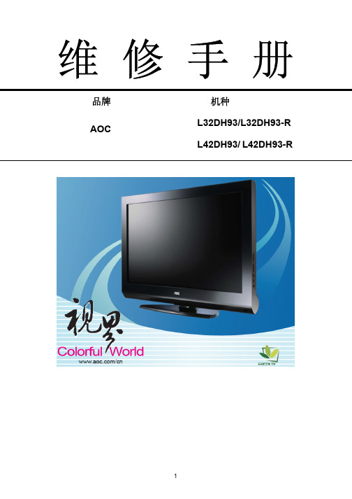
AOC液晶电视维修手册介绍
720p、1080i、1080p
视频输出 视频 AV OUT
RCA x 1、音频 L / R x 1
电脑输入 音频输出
推荐分辨率 声音输入
音频输出: L/R
1360*768/60Hz
1920*1080/60Hz
用于立体声的耳机迷你型插孔 (3.5ø)
扬声器(内置):两个 10W 扬声器
用于立体声的耳机迷你型插孔 (3.5ø)
垂直频率(Hz) 59.94 60.317 60.004 59.799 30 60 25 50 50 60 25 30
水平频率(KHz) 31.469 37.879 48.363 47.72 15.734 31.5 15.625 31.25 37.5 45 28.125 33.75
5
L42DH93
2.操作说明----------------------------------------------------------------------------------------------------------------- 07 2.1 遥控器操作 -------------------------------------------------------------------------------------------------------- 07 2.2 控制面板 ----------------------------------------------------------------------------------------------------------- 08 2.3 背面信源接口 ----------------------------------------------------------------------------------------------------- 09 2.4 侧边信源接口 ----------------------------------------------------------------------------------------------------- 10 2.5 菜单操作------------------------------------------------------------------------------------------------------------ 11
数控机床电器维修手册

z VRDY
((母主板CP) U 板)
MCON:从 CNC 到伺服放大器 (接通 MCC 以满足伺服电机的启动要求)
伺服放大器
VRDY:从伺服放大器到 CNC (确认伺服准备好)
z 更换伺服放大器 z 更换轴控制卡
信息的交换是通过 FSSB(光缆)进行。 如果 CNC 把 MCON 关断后 VRDY 一直保持接通的状态,或 CNC 启 动 MCON(MCON 接通)之前 VRDY 先接通,就会发生此报警。
在报警信息中显示出错的轴,与轴号相对应的伺服放大器和 CNC 控 制单元间的某根光缆可能出故障。 或者,到该轴号的放大器为止中有任何一个放大器出故障。
可能是由于安装在 CNC 侧的轴控制卡的不良所致。 有关各卡的安装位置,请参阅 2.4 项“印刷板上的连接插头及插卡的 配置”。
- 492 -
该文档为本人几年来维修所用的说明书特此分享给大家(非官方)
之外的值)。
#6(AXS) :1023 号参数(伺服轴号)的设定值在 1~控制轴数的范围 之外。(例如,指定 4 代替 3)或者,参数中设定值是不连 续的。
- 493 -
该文档为本人几年来维修所用的说明书特此分享给大家(非官方)
8.故障处理过程
希望能够对大家有所帮助
B-64115CM/02
8.18 700 号报警 (过热:控制单元)
8.16 462 报警 (发送 CNC 数据失败) 463 报警 (发送从属数据失败)
原因和处理 z 伺服放大器或光缆 z 轴控制卡
如果由于 FSSB 传送错误,使得从属部分(伺服放大器)不能收到正 确数据,就发生 462 报警。 如果由于 FSSB 传送错误,使得 CNC 不能收到正确数据,就发生 463 报警。 如果发生此类报警,报警信息会显示出出错轴的轴号(轴名称)。
Autork奥托克电动执行器故障维修手册[优质文档]
![Autork奥托克电动执行器故障维修手册[优质文档]](https://img.taocdn.com/s3/m/e6a95839be23482fb4da4cd1.png)
Autork奥托克电动执行器故障维修手册[优质文档] autork维修手册1( 主板接口(注:本手册中,高于3.3V的为高电平;低于0.6V的为低电平)SK11(排线口)主板正面从右到左,从右到左依次从上往下推的方式数,编号依次为 1 2 3 4 5 6 7 8 9 10 空空空相位2 开阀信相位1 关阀信地停止信12V号(高号(高号(低电平有电平有电平有效) 效) 效) SK9(电池口)主板正面从上往下,编号依次为1 2 3空地 9VSK14(24V口)主板正面从左往右,编号依次为1 2地,24VSK7(霍尔口)主板正面从右往左,编号依次为1 2 3 4 5 下拉电阻接地接霍尔板上的干接霍尔板上的一接霍尔板上的干接霍尔板上的一(霍尔板空) 簧管个霍尔(低电平簧管个霍尔(低电平有效) 有效)SK6(压力盘口)主板正面从左往右,编号依次为1 2 3 4 5 6 空压力盘电源地温度保护控力矩信号输温度保护地制线(高电平出线 5V有效保护)SK12(键盘板)主板正面从右往左,编号依次为1 2 3 4 5 6 7 8 地 Local(本STOP(停旋钮型RemoteOpenReleaseClose地) 止) (远程) (开) (松开) (关) 地,按键型电源5V SK13(模拟量口)主板正面从下往上,编号依次为1 2 3 4 5 6 7 8 空空地(模拟) 地(模拟) 空空 4-20mA4-20mA阀位反馈模拟量输入口SK1(总线板)主板正面从上往下,编号依次为1 2 3 4 5 6 7 8 9 ,12V 地 SPI SPI SPI SPI UartUartSelect(Tx) (Rx)电子故障检修方法主板无显示,指示灯不亮首先检查动力电源是否正常,然后检查电源板保险丝是否烧断,最后检查主板排线是否插牢,如果前面三项都正常,则用万用表检查SK11排线口的第5号和第9号脚看是否有大于12V的电压,如果有说明主板故障,如果没有说明电源板故障。
液晶电视维修资料大全
液晶电视维修资料大全液晶电视维修资料大全1 2 3 4 51、白光栅,有伴音(15AAB/8TT1机芯)ks4中国家电检修资料网,家电检修网,家电检修资料网- 中国最大之家电检修资料大全网创维液晶电视检修:通电开机,发现屏幕为白屏,但有伴音,分析此故障为液晶屏没有工作所致造成,查显示屏之+5V供电及行、场信号,发现没有+5V供电,查线路为主板L21,+5V供电ks4中国家电检修资料网,家电检修网,家电检修资料网- 中国最大之家电检修资料大全网电感开路更换后OK!ks4中国家电检修资料网,家电检修网,家电检修资料网- 中国最大之家电检修资料大全网2、没有光栅,有伴音(20AAA/8TT1机芯)ks4中国家电检修资料网,家电检修网,家电检修资料网- 中国最大之家电检修资料大全网创维液晶电视检修:开机后发现在强光下隐约可见图像,分析认为本机为背光灯未工作所致,拆机后通电后发现背光板没有高压产生,查背lg电视机光板供电及背光控制电平,用万用表测主板J6处电ks4中国家电检修资料网,家电检修网,家电检修资料网- 中国最大之家电检修资料大全网压。
1脚供电12V也很,但5脚在时ON应该为+5V高电平,此时却始终为0V。
顺线路查控制电ks4中国家电检修资料网,家电检修网,家电检修资料网- 中国最大之家电检修资料大全网路,J6之第5脚通过R52/1K贴片电阻接CPU-KS88C4504之第22脚,用表测CPU第22脚为+5Vks4中国家电检修资料网,家电检修网,家电检修资料网- 中国最大之家电检修资料大全网电压,R52/1K电阻一端有+5V,另一端为0V,断电后测该电阻已经开路了,更换后一切也很。
ks4中国家电检修资料网,家电检修网,家电检修资料网- 中国最大之家电检修资料大全网3、死机:(15AAB/8TT1机芯)ks4中国家电检修资料网,家电检修网,家电检修资料网- 中国最大之家电检修资料大全网创维液晶电视检修:插上电源指示灯不亮,测主板已有lg电视机+5V电压输出,查CPU电路,测CPU-KS88C4504之第12脚、第5脚、第53脚供电均也很,测CPU晶振Y2-10M也已经起振,后测复位脚第19 脚电压,也很应该为高电平,而此时为0V,查复位电路及其外围,复位电路是由一个IC(Q3-DS1813)产生之,查Q3-DS1813之供电也很,而复位输出端却为0V,更换Q3-DS1813后也很。
电磁炉维修手册
电磁炉维修手册一、简介1.1 a电磁炉道理1.2 458系列简介二、道理阐发2.1 特殊零件简介LM339集成电路2.1.2 IGBT2.2 电路方框图2.3 主回路道理阐发2.4 振荡电路2.5 IGBT鼓励电路2.6 PWM脉宽调控电路2.7 同步电路2.8 加热开关控制2.9 VAC检测电路2.10 电流检测电路2.11 VCE检测电路2.12 浪涌电压监测电路2.13 过零检测2.14 锅底温度监测电路2.15 IGBT温度监测电路2.16 散热系统2.17 主电源2.18辅助电源2.19 报警电路三、故障维修3.1 故障代码表3.2 主板检测尺度3.2.1主板检测表3.2.2主板测试不合格对策3.3 故障案例简介1.1 电磁加热道理电磁灶是一种操纵电磁感应道理将电能转换为热能的厨房电器。
在电磁灶内部,由整流电路将50/60Hz的交流电压变成直流电压,再颠末控制电路将直流电压转换成频率为20-40KHz的高频电压,高速变化的电流流过线圈会发生高速变化的磁场,当磁场内的磁力线通过金属器皿(导磁又导电材料)底部金属体内发生无数的小涡流,使器皿本身自行高速发烧,然后再加热器皿内的东西。
1.2 458系列筒介458系列是由建安电子技术开发制造厂设计开发的新一代电磁炉,介面有LED发光二极管显示模式、LED数码显示模式、LCD液晶显示模式、VFD莹光显示模式机种。
操作功能有加热火力调节、自动恒温设定、按时关机、预约开/关机、预置操作模式、自动泡茶、自动煮饭、自动煲粥、自动煲汤及煎、炸、烤、火锅等料理功能机种。
额定加热功率有700~3000W的不同机种,功率调节范围为额定功率的85%,而且在全电压范围内功率自动恒定。
200~240V机种电压使用范围为160~260V, 100~120V机种电压使用范围为90~135V。
全系列机种均适用于50、60Hz的电压频率。
使用环境温度为-23℃~45℃。
电控功能有锅具超温庇护、锅具干烧庇护、锅具传感器开/短路庇护、2小时不按键(忘记关机) 庇护、IGBT 温度限制、IGBT温渡过高庇护、低温环境工作模式、IGBT测温传感器开/短路庇护、上下电压庇护、浪涌电压庇护、VCE按捺、VCE过高庇护、过零检测、小物检测、锅具材质检测。
冠捷液晶显示器维修必备指导书(pdf 65页)

T560K保密资料内部使用2技术服务中心REV:012002年10月前言本手册经由魏吓凤、高志远两位工程师几周的努力,终于呈现在各位CS同仁面前。
本手册凝聚了STS工程师的经验与智慧,是他们维修LCD Monitor的经验结晶。
本手册主要是作为大家维修LCD时参考使用手册中所列之点位,希望各们同仁在维修之前先行熟悉,维修时再按图索骥,即可事半功倍。
由于时间仓促、经验不足无法涉猎所有的故障,请各位同仁多多包涵,如有疑难问题请与售后服务技术支持部联系。
TEL:O591-52715163目录仪器设备及焊接技巧 (5)TFT LCD成像原理 (7)T560K LCD概述.......... .. (14)T560K 自产ADPTER原理 (15)升压板电路原理 (23)T560K 主板电路分析 (29)T560K LCD维修流程图 (45)T560K主板电路原理图 (57)GMZAN1管脚功能 (60)45一、仪器设备:¾CHROMA 2000以上的(信号发生器)¾20MHZ 示波器¾防静电温控烙铁¾静电手环¾防静电桌垫¾IC拔焊台(用于拔四列IC集成块,目前不良较少,可暂不考虑使用)二、注意事项:1、烙铁保养注意事项¾在进行焊接前,必须先把清洁海绵加水,再挤干多余的水份,作为清洁烙铁头之用。
¾工作后,先把电源切断,然后清洁焊咀,再加上一层新焊锡以保护烙铁头。
2、焊接注意事项¾烙铁温度可控制在430°左右。
¾清除锡渣时尽量避免使用吸锡器防止翘皮。
¾焊接时,请勿用力过大,否则会使焊咀变形。
¾焊接时间最好控制在3秒以内,防止良品元件损坏。
3、所有接触到LCD电路板的设备均要有良好的接地三:拆除贴片元件要点:1、在不良元件两端堆加焊锡。
2、可适量加点助焊剂。
3、用烙铁头的扇面直接接触贴片元件使焊锡熔化。
AOC液晶电视维修手册介绍

视频 AV S端
RCA x 2 S-Videox 1
音频 L / R x 1
分量输入 YPbPr/YCbCr
YPbPr/YCbCr x 2
音频 L / R x 2
分量输入支持模式
480i 、 576i 、 480p 、 576p 、 480i 、 576i 、 480p 、 576p 、
720p、1080i
模式
VESA VESA VESA VESA CVI CVI CVI CVI VESA CVT VESA CVT CVI CVI CVI
垂直频率(Hz) 59.94 60.317 60.004 59.799 30 60 25 50 50 60 25 30 60
水平频率(kHz) 31.469 37.879 48.363 47.72 15.734 31.5 15.625 31.25 37.5 45 28.125 33.75 67.5
电脑格式
编号
分辨率
1
640×480
2
800×600
3
1024×768
4
1360×768
5
1440×900
6
1680×1050
*7
1920×1080
*推荐分辨率
模式 VGA VESA VESA CVT CVT CVT CVT
垂直频率(Hz) 59.940 60.317 60.004 59.799 59.887 59.954 60
cn903的pin89是否有24v电压输出forl42dh93更换电源板更换panel18亮线亮带白斑黑斑漏光亮点超规等更换panel花屏白屏检测lvds接口和线材是否良好重插或更换lvds线先更换主板检测是否ok更换panelosd乱码切换频道时间长切换频道瞬间画异检测软体版本是否需要更新更换主板升级软体画面扭曲超频长宽比例失调中心偏移截边上下或左右有黑带等进入菜单进行自动调整或复位看是否ok检测输入信号格式是否在tv的支持范围内调整输入信号格式更换主板19彩条水波纹画抖画闪鬼影残影拖影等干扰检测信号源出信号是否正常重新设置信号源检测信号线是否良好更换信号线排除干扰源先更换主板检测是否ok更换paneltv画面雪花点重影细线条纹干扰检测tv信号线是否接触不良重新连接tv信号线检测附近是否有高频干扰源排除干扰源用场强仪检测信号强度是否在45100db之间65db左右为最佳值更换主板太弱
亚威售后客户培训手册(数控折弯机)

全自动模式:在该方式下可以自动执行已选定的程序。
半自动模式:在该方式下,选定的程序一步一步的执行。
2.3数控系统操作界面各功能区域介绍
现场服务人员简单介绍
2.4机器运行状态介绍(滑块、后挡料工作状态)
显示的格式如下:
Y1=100.21 Y2=100.25 Y-轴状态=1 X-轴状态=1 Delem 1995,1997
其中Y1=100.21 Y2=100.25为左右油缸(滑块)的位置,
Y-轴状态=1 ---------------表明滑块的状态为停在“上死点”。
Y轴状态的变化及定义如下:
Y-轴状态=2 ---------------滑块处于“快下”状态。
输入密码25789进入参数页面
进入X轴参数的反馈页面“参考点位置”
假设X=实际尺寸-理论尺寸
那么新参考点=原参考点+X
将参考点改完后保存并重启数控系统,其他辅助轴的修正方法同X轴。
b. Y轴参考点的校正方法:
1)用一块板材放在下模上,在数控系统操作页面输入正确的板厚、上下模、折弯角度180°
2)踩下脚踏开关,滑块运行至下死点,此时板料应该正好被压住,不能被抽出,也不能有压痕。此时参考点是正确的。
滑块向上运动寻找Y1、Y2轴的参考点,当滑块分别经过左右光栅尺的REF点后,滑块将停在上死点。Y轴的参考点寻找完成。
后挡料机构往后运动寻找X轴的参考点,运动到后RSD开关处等待其它轴(X1轴、R轴、Z1轴、Z2轴)寻找到参考点并定位完成后,后挡料X轴反向向前寻找到参考点并定位到手动页面中所编程的X值。假如后挡料只配置了X轴时,后挡料将直接反向寻找到参考点并定位完成。
Compaq Presario桌面电脑产品升级与维修指南说明书

Compaq Presario Desktop Products upgrading and servicing the pcThe information in this document is subject to change without notice.Hewlett-Packard® Company makes no warranty of any kind with regard to this material, including, but not limited to, the implied warranties of merchantability and fitness for a particular purpose.HP shall not be liable for errors contained herein or for incidental or consequential damages in connection with the furnishing, performance, or use of this material.HP assumes no responsibility for the use or reliability of its software on equipment that is not furnished by HP.This document contains proprietary information that is protected by copyright. All rights are reserved. No part of this document may be photocopied, reproduced, or translated to another language without the prior written consent of HP.Hewlett-Packard CompanyP.O. Box 4010Cupertino, CA 95015-4010USA© 2001-2003 Hewlett-Packard Development Company, L.P. All rights reserved.Hewlett-Packard is a registered trademark of Hewlett-Packard Company in the United States of America and other countries/regions.This product incorporates copyright protection technology that is protected by method claims of certain U.S. patents and other intellectual property rights owned by Macrovision Corporationand other rights owners. Use of this copyright protection technology must be authorised by Macrovision Corporation, and is intended for home and other limited viewing uses only unless otherwise authorised by Macrovision Corporation. Reverse engineering or disassembly is prohibited. Apparatus Claims of U.S. Patent Nos. 4,631,603, 4,577,216, 4,819,098, and 4,907,093 licensed for limited viewing uses only.Other brand or product names are trademarks of their respective holders.HP supports lawful use of technology and does not endorse or encourage the use of our products for purposes other than those permitted by national copyright law.table of contentsupgrading and servicing the pc (1)preparing the pc (1)removing or upgrading a drive (3)locating drive positions (3)removing a drive (3)replacing or adding a drive (5)upgrading or replacing memory (7)removing a memory module (7)replacing or adding a memory module (8)removing or installing an expansion card (9)reassembling the pc (10)upgrading and servicing the pc iiiiv upgrading and servicing the pcupgrading and servicing the pc 1upgrading and servicing the pcThis guide describes procedures for accessing the internal parts of the PC and installing components.NOTE: The procedures for the S0000 and 8000 seriesmodels are the same except where noted.8000 series model and S0000 series modelpreparing the pcBefore you upgrade any component in your PC, you need to prepare the PC so that you can safely handle it and the components.CAUTION: Static electricity can damage the electronic components of the PC or optional equipment. Ensure that you are discharged of static electricity by briefly touching a grounded metal object.1 Remove any diskette or optical disc (CD or DVD) from the PC.2 Click the Start button, and then click T urn Off Computer . Click T urn Off to turn the PC off.3 Disconnect the modem/telephone cable, if present.4 Disconnect the power cable from the electrical outlet (1) and then from the PC (2).disconnecting the power cableWARNING: To reduce the risk ofpersonal injury from electrical shock and hot surfaces, disconnect the power cable from the wall outlet, and allow the internal system components to cool before touching.5 Disconnect all external devices connected to the PC.2 upgrading and servicing the pc6 Lay the PC on its side with the access panel (the side with the pull grip) facing up.7 Remove the access panel by loosening the screw(s) (1) that secure the access panel to the PC chassis. Slide the access panel back (2) about 1 inch (2.5 cm), and then lift it up and off the unit.removing the pc access panel on the S0000 series modelWARNING: Beware of sharp edgesinside the chassis.removing the pc access panel on the 8000 series8 Remove the front bezel by following the appropriate method for your PC model.• To remove the front bezel from the S0000 seriesmodel, gently pry the top section (1) of the bezel away from the chassis. On the inside of the front bezel, press the centre two tabs (not the bottom tabs) to release the bezel, and then pull it from the chassis (2).removing the front bezel from theS0000 series• To remove the front bezel from the 8000 series,push up on the two release tabs (1), and then rotate the front bezel away from the chassis to release it (2).removing the front bezel from the8000 seriesupgrading and servicing the pc 3removing orupgrading a driveDepending on your PC configuration, you may have up to four of the following storage drives in your PC:• CD-ROM or CD-RW drive• DVD-ROM or DVD+RW/+R drive • Hard disk drive • Diskette drive• 7-In-1 memory card reader (select models only)You need a screwdriver to replace any of the drives.CAUTION: Back up your personal files on the hard disk drive to an external storage device, such as a CD, before removing the hard disk drive. Failure to do so will result in data loss. Afterreplacing the hard disk drive, you need to run System Recovery using the recovery discs to load the factory-installed files. See “using application recovery and system recovery” for details.locating drive positionsdrive positions on the S0000/8000 series (S0000 shown)1 Optical drive, may be a CD-ROM, CD-RW, DVD-ROM, or DVD+RW/+R drive2 Second optical drive, may be a DVD-ROM, DVD+RW/+R, CD-ROM, CD-RW drive, or 7-In-1 memory card reader (select models only)3 Diskette (floppy) drive4 Hard disk driveremoving a drive1 Locate the drive you want to remove.2 Complete the procedure described in “preparing the pc” on page 1.3 Disconnect the power cable (1) and data cable (2) from the back of the drive you want to remove, as indicated in the following illustrations. Use a gentle rocking motion. Some units may have a sound cable. If so, disconnect the sound cable (3).disconnecting the optical drive cablesreader cable4 upgrading and servicing the pcdisconnecting the diskette (floppy) drive cablesdisconnecting the hard disk drive cables4 Release the drive from the chassis by following the method appropriate for your PC model:• To release a drive from the chassis of the S0000series, lift the release tab (1) on the latch drive bracket of the drive you want to remove, and then slide the drive from its drive bay (2). (The latch drive bracket secures the drives in their respective positions in the chassis.)removing a drive from the S0000 series• To release an optical drive or diskette drivefrom the chassis of the 8000 series, slide the drive lock mechanism (1) to unlock the drive in the drive bay and pull the drive out of the drive bay (2).removing an optical or diskette drive from the 8000 series• To release a hard disk drive from the chassis ofthe 8000 series, slide the drive lock mechanism (1) to unlock the drive in the drive bay, remove the metal drive shield (2) by pressing and lifting the two tabs on one side of the shield, and then pull the drive out of the drive bay (3).upgrading and servicing the pc 5142removing a hard disk drive from the 8000 series5 For both the S0000 and 8000 series, if you are replacing the old drive with a new drive, remove the four screws (4) (two on each side) from the old drive. You need these screws to install the new drive.NOTE: If you have the S0000 series, and youremoved a 7-In-1 memory card reader, continue to step 7; otherwise, you are finished with the task of removing a drive from the chassis.If you have the 8000 series, and you removed a hard disk drive, a 7-In-1 memory card reader or an optical drive, you are also finished with thistask. If you have the 8000 series, and you removed a diskette drive, continue to step 6.6 For an 8000 series diskette drive, squeeze inward on both sides of the bracket brace, and lift the brace up and out (1). Remove the two sets of screws (2) (left and right sides) that secure the drive to the drive adapter. Lift the diskette drive out of the drive adapter (3) by sliding the drive back and then up. Ensure that the guide screws (4) (left and right sides) are left in the drive adapter. You are finished with the task of removing the drive.removing a diskette drive from the drive adapter on the 8000 series7 For the S0000 series 7-In-1 memory card reader, remove the reader from the drive bay adapter if the adapter is not included with your replacement reader. Remove the two screws (left and rightsides) that secure the reader to the adapter. Lift the reader out of the adapter by sliding the readerback and then up. You are finished with the task ofremoving the reader.removing a 7-In-1 memory card reader from the drive bay adapter on the S0000 seriesreplacing or adding a driveThe steps to replace or add a drive are the same for both the S0000 and 8000 series, except when you are replacing a diskette drive on the 8000 series, or the 7-In-1 memory card reader on the S0000 series.6 upgrading and servicing the pcIf you are replacing a diskette drive on the 8000 series, before starting step 1 in the followinginstructions, you need to fit the diskette drive in a diskette drive adapter as described in “reassembling the diskette adapter” on page 7.If you are replacing a 7-In-1 memory card reader, before starting step 1 in the following instructions, reassemble the reader in the drive bay adapter as described in step 7 of “removing a drive” on page 3. If you are replacing or adding any other drive, begin with step 1 in the following instructions.to replace or add a drive1 Insert four guide screws into the sides of the drive (two on each side). The screws help guide the drive into its proper position in the bay.• When replacing a drive on the S0000 and 8000 series, place the screws, that you removed from the old drive, into the new drive.• When adding a second hard disk drive on the8000 series, use the four extra guide screws that are attached to the chassis under the front bezel. 2 Slide the drive into the drive bay (1), making sure to align the guide screws with the guide slots,until it snaps into place.sliding the drive into the drive bay on the S0000/8000 (S0000 shown)3 Reconnect the power and data cables to your drive as indicated in the following illustrations.cable on the S0000 seriesreconnecting the diskette drive cablesreconnecting the hard disk drive cablesreconnecting the optical drive cablesNOTE: An optical drive for the 8000 series mayinclude a sound cable. Connect this cable also.4 Complete the procedure described in“reassembling the pc” on page 10.5 Turn on the PC.reassembling the diskette adapterTo replace or add a new diskette (floppy) drive on the 8000 series, you need to reassemble the adapter around the diskette drive. (The S0000 series does not need an adapter.)1 Lower the diskette drive into the adapter (1).Ensure that the holes are aligned, and replace the screws (2) that secure the diskette drive to theadapter.2 Press inward on each side of the bracket brace (3),and lower the bracket until it snaps into place over the diskette drive. Ensure that the guide screws (4) are installed in the adapter.3 Return to “replacing or adding a drive” on page 5,and begin with step 1.replacing the diskette drive adapter onthe 8000 seriesupgrading or replacing memoryYour PC comes with random access memory (RAM), which temporarily stores data and instructions on your PC. You can install memory expansion modules in the memory expansion slots in the PC. The procedures for upgrading or replacing these modules are the same for the S0000 and 8000 series. removing a memory moduleCAUTION: When handling a memorymodule, be careful not to touch any ofthe contacts. Doing so may damage themodule.1 Complete the procedure described in “preparingthe pc” on page 1, but do not remove the frontbezel.2 Locate the memory module inside your PC. Seethe following illustration for the location of thememory modules (1), memory slots (2), andrelease latches (3) on the system board.upgrading and servicing the pc 78 upgrading and servicing the pclocating the memory moduleNOTE: The location and number of memorymodules may vary slightly by model.3 Open both latches of the memory module socket (1) found at each end of the memory module. Lift the memory module (2) from the memory slot.removing a memory modulereplacing or adding a memory moduleUpgrade the memory in your PC with memory of the same type and speed as the memory originally installed in your PC.CAUTION: When handling a memory module, be careful not to touch any of the contacts. Doing so may damage the module.1 Open both latches of the memory module socket (1).opening the latches on the memory module socket• If you are replacing a memory module, put thenew memory module in the same memory slot from which the old memory was removed. • If you are adding a memory module, install thenew module into the socket nearest the preinstalled module, and install additional modules in the next available sockets.2 The memory module can be installed in only one way. Match the notch on the module (1) with the tab on the memory socket. Push the modulecarefully and firmly into the slot, ensuring that the latches (2) on both ends snap into place.installing a memory moduleupgrading and servicing the pc 93 Complete the procedure described in “reassembling the pc” on page 10.NOTE: If a blank screen is displayed after replacingor adding a memory module, the memory is installed incorrectly or it is the wrong type of memory. Remove and reinstall the memory module.removing or installing an expansion cardAn expansion card is a circuit board that fits into a PC expansion slot. Your PC contains severalexpansion slots that can be used to add components to your PC. Component configurations vary by model.Expansion cards you can replace or add to your PC include:• Modem• Network Interface Card (NIC) • Graphics Card • Sound Card• FireWire (IEEE 1394) Auxiliary CardA Phillips screwdriver is needed to remove, replace or add an expansion card.to remove an expansion card1 Complete the procedure described in “preparing the pc” on page 1, but do not remove the front bezel.• To remove an expansion card from the S0000series, continue to step 2. • To remove an expansion card from the 8000series, skip to step 3.2 On the S0000 series, on the rear of the PC, remove the expansion bracket covering the expansion slots by removing the screw from the bracket cover (1), and then remove the expansion bracket cover (2).removing the screw and expansion bracket cover on the S0000 series3 Inside the PC on either the S0000 or 8000 series, locate the expansion slots on the system board.• If you have the 8000 series, continue to step 4. • If you have the S0000 series, skip to step 5.4 On the 8000 series, remove the screw that secures the expansion card to the chassis.5 Remove the expansion card from either an S0000 or 8000 series by holding the card at each end, and carefully rocking it back and forth until theconnectors pull free from the socket. Be sure not to scrape the card against the other components.removing an expansion card on the S0000/8000 (S0000 shown)6 If you are not replacing the old expansion card with a new expansion card, reinstall the expansion slot cover to close the open slot. Insert the metal slot cover into the opened slot, and screw a screw into the top of the cover to secure it in place.10 upgrading and servicing the pcto install an expansion card1 If you are replacing or adding a new expansion card, in either the S0000 or 8000 series, align the edge of the expansion card with the slot on the chassis and gently, but firmly, press the cardstraight down into the expansion slot. The whole connector should be seated properly in the expansion slot.replacing or adding an expansion card on the S0000/8000 (S0000 shown)• If you have an 8000 series, continue to step 2. • If you have an S0000 series, skip to step 3.2 For the 8000 series, secure the expansion card to the chassis with the slot cover screw.3 For both the S0000 and 8000 series, if you have replaced an expansion card, store the old card in the anti-static packaging that contained your new card.• If you have an S0000 series, continue to step 4. • If you have an 8000 series, skip to step 5.4 For the S0000 series, replace the expansion cover bracket (1) and screw (2).replacing the expansion bracket cover on the S0000 series5 For both the S0000 and 8000 series, complete the procedure described in “reassembling the pc” on page 10.reassembling the pc1 Replace the front bezel by following the method appropriate for your PC model.• To replace the front bezel on the S0000 series,position the chassis in the upright position. At an angle, align the top of the front bezel with the top slots of the chassis (1) so that the front bezel hooks onto the chassis, and then press the bottom end of the bezel to the chassis until it snaps into place (2).replacing the front bezel on the S0000 seriesupgrading and servicing the pc 11• To replace the front bezel on the 8000 series, laythe chassis on the side with the open side up. Place the front bezel in the correct position. Ensure the slots (2) are aligned correctly, and rotate the bezel toward the chassis (1) until it snaps into place.replacing the front bezel on the 8000 series2 For either the S0000 or 8000 series, place the side access panel in the proper position on the chassis and slide it into place (1). Ensure that the hole for the thumbscrew(s) align with the hole in the chassis (2), and replace the thumbscrew(s).replacing the side access panel on the S0000seriesreplacing the side access panel on the 8000 series3 Reconnect the power cable (1) to the PC, and plug the cable into an electrical outlet (2).reconnecting the power cable on the S0000/8000 (S0000 shown)4 Reconnect the modem/telephone cable, if present.5 Reconnect all peripheral devices to the PC.WARNING: To reduce the risk of electrical shock, fire, or damage to the equipment, do not plug telecommunications or telephone connectors into the network interface card (NIC) (sometimes labelled as an Ethernet connector).6 Turn on the PC by pressing the On button.Printed in。
科诺电磁炉维修服务手册
科诺电磁炉维修服务手册(05版)编制:审核:批准:目录一.前言二.电磁炉的工作原理三.电磁炉各主要环节原理说明四.整机原理框图五.电磁炉内部结构六.故障检查及流程七.维修方法及注意事项八. 故障检查流程图九.故障代码的检修十.原理图一、前言本维修手册适用于科诺电磁炉各款机型(除开关电源外)。
电磁炉原理上均基本相同,故主板电气原理相同,操作面板和输出功率有区别。
功率不同的电磁炉所采用的IGBT型号也不同。
维修时不能搞错。
二、电磁炉的工作原理电磁炉工作原理是基于电磁感应加热的原理。
由于电磁炉没明火所以从安全性的角度出发它优于电阻丝加热的普通电路和燃气灶具,不容易引起火灾或瓦斯中毒的危险。
它的基本原理是先将交流电整流成直流电,随后再将直流电变成高频交流电(AC-DC-AC)高频交流电的频率通常在20KHZ~30KHZ之间,我们把高频交流电送入一扁平的线圈,使之产生高频交流电磁场。
如果把铁磁性的锅具至于该磁场中间那么磁场就会在锅底产生涡流而变成热量,将锅底加热。
显而易见前提是锅底本身必须由不锈钢或铁制成。
由于加热只能在锅底产生,可以不容易被灼伤,也不会将周围空气加热或者因风而使锅底熄灭因此热效率明显高于用明火加热的方式,安全性也强于其它炉子。
微电脑电磁炉是在控制电路中加入了主控CPU芯片,使之电磁炉使用更为方便可靠。
例如CPU芯片可以很圆满的完成过电压、过电流、过热、定时、恒功率加热,以及大功率开关元件的保护等的功能。
由直流电变为高频交流通常称为逆变。
逆变主要由大功率晶体管(GTK)或IGBT等电力电子器件来完成。
三、磁炉主要环节的工作原理说明1.输入部分:压敏电阻器(ZR)主要用以防止过高的浪涌电压进入电磁炉造成炉子损坏。
通常选用430~470V等级的电压。
一旦发生电网上存在浪涌电压(例如雷击或断开电感性负载时容易在电网上产生浪涌)时压敏电阻就会将这部份能量消耗掉。
甚至会由于通过压敏电阻的大电流将熔断器烧断而切断电源。
微波组合烤箱维护和修理手册说明书

微波组合烤箱维护和修理手册 CE – CN目录1一般信息41.1EC 合格证明51.2环境保护71.3重要信息81.4识别微波组合烤箱91.5技术文档的结构101.6本《维护和修理手册》简介112设计和功能132.1微波组合烤箱的设计和功能142.2操作面板的布局和功能163为了您的安全173.1基本安全守则183.2微波组合烤箱的指定用途233.3微波组合烤箱的警告标志243.4危险概述263.5移动设备时的危险和安全预防措施283.6设置设备时的危险和安全预防措施293.7安装设备时的危险和安全预防措施303.8准备设备供使用时的危险和安全预防措施313.9清洁设备时的危险和安全预防措施323.10维护和修理设备时的危险和安全预防措施343.11停用设备时的危险和安全预防措施363.12安全装置373.13工作人员和工作岗位需要满足的要求393.14个人防护装备404设置设备424.1设置设备时安全工作434.2安装位置的要求444.3将设备安装到工作台上465安装475.1电气安装过程中安全工作485.2规划电气安装495.3电气安装要求516准备设备供使用536.1准备设备供使用时安全工作546.2准备设备供使用的程序566.3主菜单屏幕586.4键盘屏幕596.5使用 USB 存储棒607清洁程序627.1日常清洁任务637.2清洁用化学品64 7.3清洁必备物品65 7.4清洁时安全工作66 7.5清洁程序68 7.5.1清洁前的冷却程序69 7.5.2清洁说明728技术数据77 8.1技术数据78 8.2尺寸图809诊断81 9.1检查设备的状况82 9.2错误与诊断86 9.3故障查找9310测试98 10.1测试组件时安全工作99 10.2要求101 10.3测试选定组件(外壳已安装)102 10.4高压组件(外壳已拆除)110 10.5电源电压组件(外壳已拆除)11411固件115 11.1固件更新116 12更换组件13112.1更换设备零部件时安全工作132 12.2概览134 12.3拆除/安装外壳139 12.4拆除/安装门组件142 12.5更换磁控管147 12.6更换冷却风扇152 12.7更换 QTS(快速触摸屏)组件154 12.8更换 SRB(智能继电器板)158 12.9更换触摸屏覆盖物160 12.10调节门微动开关/联锁装置162 12.11更换搅拌器电机164 12.12更换对流风扇电机168 12.13更换变压器(高压)171 12.14拆除对流风扇电机速度控制器174 12.15概述——其他组件17613电路板和电路图183 13.1SRB / QTS 电路板184 13.2电路图18914调试设备1911 一般信息本章目的本章将告诉您如何识别微波组合烤箱,并指引您如何使用本手册。
一体机维修手册
炫智机型维修手册1、问题:屏幕不开机,指示灯不亮。
提示:(1)机器所用AC110/220V插座是否有电。
(2)电源线是否连接到位,IO开关是否打开。
(3)机器内部电源连接线是否连接牢固。
(4)机器内部电源转接板保险管是否烧坏。
(5)机器内部电源板直流电压是否输出正常。
2、问题:屏幕不亮,指示灯亮红灯,但无法转为绿灯。
提示:(1)机器内部按键板、遥控板到TV驱动板之间的连接线是否连接正常。
(2)TV驱动板直流电压接口的12V、5V电压是否正常.3、问题:屏幕不亮,背光不亮,指示灯亮绿灯。
提示:(1)机器背光控制线是否连接正常。
(2)机器液晶屏背光供电线连接是否正常。
(3)检查机器液晶屏背光供电线24V电压是否正常(4)检查机器液晶屏背光控制线电压是否正常4、问题:屏幕不显示,背光亮,指示灯亮绿灯。
提示:(1)机器屏线连接是否正常。
(2)机器120HZ转接板供电是否正常。
5、问题:机器屏幕花屏。
提示:(1)机器屏线连接是否正常。
(2)机器TCON板到液晶屏之间的排线连接是否正常。
6、问题:机器开机有显示,但背光只亮一半。
提示:(1)机器恒流源板到屏背光模组连线是否正常。
7、问题:机器开机有显示,但图像有水印、字体不正常。
提示:(1)屏参是否设置正确。
安卓818主板:1、按遥控MENU键,然后按数字键6-1-5-1进入工厂菜单。
2、按MENU键进入二级工厂菜单。
按上下键选择Otheroption。
3、分别设置“Panel BitMode”、“Panel TiMode”、“Panel AB Swap”、“Panel Mirro”选项,直到屏幕显示正常。
182主板:(1)遥控“信号源(Input)”键,然后按数字键2-5-8-0进入工厂菜单。
(2)选择“LVDS SET”选项,设置“LVDS TI MODE”和“LVDS SW AP”选项,直到屏幕显示正常。
8、问题:机器开机正常显示,但遥控器无作用。
提示:(1)遥控器电池电量是否充足。
AOC 919Sw维修手册
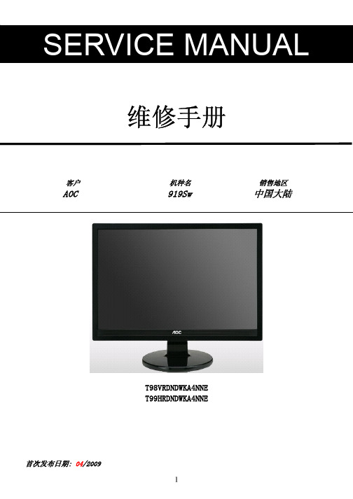
维修手册客户 机种名 销售地区AOC 919Sw 中国大陆T98VRDNDWKA4NNET99HRDNDWKA4NNE首次发布日期: 04/2009目录1.安全与注意事项------------------------------------------------------------------------------------------------------032.技术规格---------------------------------------------------------------------------------------------------------------053.操作说明及工厂模式调整------------------------------------------------------------------------------------------084. ISP升级流程---------------------------------------------------------------------------------------------------------125.故障处理流程---------------------------------------------------------------------------------------------------------156.电气方框图------------------------------------------------------------------------------------------------------------197. PCB分布图-----------------------------------------------------------------------------------------------------------208.线路图------------------------------------------------------------------------------------------------------------------259.爆炸图------------------------------------------------------------------------------------------------------------------3310. BOM------------------------------------------------------------------------------------------------------------------3411. BOM差异比较-----------------------------------------------------------------------------------------------------421.安全与注意事项FCC 注意事项FCC B 类无线电频率干扰声明警告:(对于 FCC 认证的型号)注意:本设备已经通过测试,符合 FCC 规定第 15 部分有关 B 类数字设备的限制。
AOC工厂换灯管规范教程
6.装灯管 6.装灯管
6.1 装上灯管: 先测试已修灯管的好坏,接着分清导光板,反射片的正反面 和上下边缘,分清上下灯管,然后把导光板和反射片一起卡入上下灯管的 槽内。 注意事项: 1).要先测已修灯管的好坏,如果有新的原装灯管可从“拆灯管”步骤 后直接到这一步骤(即省了拆装灯管组件的步骤)。 2).要分清导光板,反射片的正反面及上下边缘,分清上下灯管及灯 管的朝向。 3).装灯管时要卡到位,装不上时不要硬装,须先查明原因,灯管两 端超出导光板的部分须相等。
6.7 装上PCB板上的螺丝,粘好绝缘保护膜。 注意事项: 1).此时查看是否有遗漏了什么部件及各部件是否卡好。
29
7.维修后检验 7.维修后检验
7.1 维修后检验 有无异物或漏光等现像。
30
Thank you! ---End---
19
5.安装裸灯管及其组件 5.安装裸灯管及其组件
5.2焊接灯管:在高压灯管线端套上热缩套管(规格:直径2mm长度 10mm),在低压灯管线端套上热缩套管(规格:直径1.5mm长度10mm), 焊上灯管线,并把热缩套管移到焊接处热缩。 注意事项: 1).操作时小心灯管断裂。 2).灯管高压端要焊成直角型,低压端焊成一字型。 3).焊点要圆,不能有毛刺,防止放电打火; 焊点不宜过大或过小。 4).同一个灯管PIN上的高低压线须焊在同一个裸灯管上。
1.更换灯管前的准备 1.更换灯管前的准备
1.1更换灯管须选择一个无尘的环境:无尘室或洁净台。(上图为洁净台) 备注:CS站目前无洁净台设备,可选用干净的空间更换灯管。
1.更换灯管前的准备 1.更换灯管前的准备
1.2更换灯管前的工具准备: 小一字螺丝刀一把,小十字螺丝刀一把,橡胶手套一副,测灯管治具一 个,新的灯管一根,7805 IC一个,直径1.5mm,2mm,4mm的三种规格热 缩套管若干,海棉垫一个,无尘布一块,以及电烙铁,信号源,静电手环等。 (部分工具如上图)
- 1、下载文档前请自行甄别文档内容的完整性,平台不提供额外的编辑、内容补充、找答案等附加服务。
- 2、"仅部分预览"的文档,不可在线预览部分如存在完整性等问题,可反馈申请退款(可完整预览的文档不适用该条件!)。
- 3、如文档侵犯您的权益,请联系客服反馈,我们会尽快为您处理(人工客服工作时间:9:00-18:30)。
品牌 AOC
机种 T2369M-T2369Z
1
版本 A00
发布日期 2013-2-21
变更说明
变更说明 首次发布
对外机种名 T2369M T2369Z
对内机种名 E23CG1NDBQA8NNF.LF E23CG1NDBQA7NNF.LF
2
目录
1. 技术规格 ---------------------------------------------------------------------------------------------------------------- 04 1.1 一般规格 ------------------------------------------------------------------------------------------------------------04 1.2 预设显示模式 ------------------------------------------------------------------------------------------------------05
On/Off
执行动作
不可调整
工厂菜单说明
TV AV/S Comp HD PC
注释
oo
o
o o 客户名称
oo
o
o o 发布软体 Main-MCU 版本
oo
o
o o 发布软体 Bootloader 版本
oo
o
o o 发布软体 Sub-MCU ver 版本
oo
o
o o 发布软体 EEPROM 版本
oo
o
o o 软体发布日期
图一
调整规格是写在白平衡程式里面的,检验以产品规格为准, 如下: Warm (x=0.313± 0.030, y=0.329± 0.030)/6500K (80%white) Normal (x=0.285± 0.030, y=0.293± 0.030)/9300K (80%white) Cool (x= 0.270± 0.030, y= 0.273± 0.030)/12000K (80%white)
√
√ √ 在 Auto Color 做完立即更新,并可手动调整。
√√
√
√ √ 在 Auto Color 做完立即更新,并可手动调整。
√√
当前设置的色温,该项可切换色温模式,并正确显示色温名称,对应色温
√
√ √ 的 Scaler Gain & Offset RGB 值等相关信息同步更新。
√√
√
√ √ Scaler Gain 值在白平衡调整时立即更新,并可手动调整。
26
Total time
不可调整
oo
Black light
根据 IC SPEC *
*
Language
支持语言
*
*
Energy LOGO
On/Off
*
*
Reset
执行动作
√√
Exit
执行动作
√√
o
o
o
AC ON 主电源供电总计时,在 EEPROM Initial 或 Factory reset 后都清为 0,显示值用十进制表示,当时间到达显示最大值时就不再变化。
主菜单的 OSD 默认值,工厂菜单的 ADC 数据,白平衡设定值,Black light
√
√ √ 和 Language 等,同时把 Burn in 设置为 On,响应工厂遥控器功能,设置
输入源为 TV。
o
o
o
背光打开总计时,在 EEPROM Initial 或 Factory reset 后都清为 0,显示 值用十进制表示,当时间到达显示最大值时就不再变化。
5.1 主板--------------------------------------------------------------------------------------------------------------------28 5.2 电源板-----------------------------------------------------------------------------------------------------------------37 5.3 IR 板-------------------------------------------------------------------------------------------------------------------39 6.软体及 EDID 烧录 ------------------------------------------------------------------------------------------------------40 6.1 软体烧录 -------------------------------------------------------------------------------------------------------------40 6.2 EDID 烧录 -----------------------------------------------------------------------------------------------------------41 7.故障处理流程 ----------------------------------------------------------------------------------------------------------- 42 8.主要 IC 管脚及内部框图 ----------------------------------------------------------------------------------------------48 9. BOM----------------------------------------------------------------------------------------------------------------------52
24
6. 再将 Chroma 设置为 T314/P141 7. Current Source 切为 component 8. 再选择 Color temp 选择色温模式(Cool、Normal、Warm) 9. 选择 OK 后再选择 Gain 栏调整 R/G/B 值,将色温规格调整至要求范围内。
白平衡值检查: Current Source 选择为“视频”/T303/P141、HDMI/T347/P141 色温规格也需在规格范围内,此时白平衡调 整 OK。
2.操作说明 ----------------------------------------------------------------------------------------------------------------- 06 2.1 遥控器操作 ---------------------------------------------------------------------------------------------------------06 2.2 控制面板和侧面信源接口 ---------------------------------------------------------------------------------------07 2.3 菜单操作 ------------------------------------------------------------------------------------------------------------08
图二
注: 下页是关于一般工厂菜单的说明(和本机并非完全相同),仅供参考! 25
选项名称 Brand
Main-MCU ver Bootloader ver Sub-MCU ver EEPROM ver
Date Model name
Scaler Panel type Current source
Auto color ADC Gain ADC Offset
Color temp.
Scaler Gain Scaler Offset
Burn in
EEPROM Init
Back LIT time
调整范围 不可调整 不可调整 不可调整 不可调整 不可调整 不可调整 不可调整 不可调整 不可调整 支持输入源
执行动作 根据 IC SPEC 根据 IC SPEC
支持色温 根据 IC SPEC术规格
1.1 一般规格
4
1.2 预设显示模式
5
2.操作说明
2.1 遥控器操作
6
2.2 控制面板和侧面信源接口
7
2.3 菜单操作
打开和关闭电视
8
9
10
11
12
13
14
15
16
17
18
19
20
21
22
23
3.工厂模式调整
注: 此处仅以 LE32R17M 图片为例来说明。 Components ADC 调整: 1. 将 Chroma 设置为 T314/P185 2. 按“菜单+1+9+9+9+回看”进入工厂模式 3. 将 Current Source 选择为“分量信号” 4. 再选择 Auto Color 按确认键后,待显示为 Pass 则 Components ADC 调整 OK 5. 将 Chroma 设置为 T312/P185 6. 再选择 Auto Color 按确认键后,待显示为 Pass 则 Components ADC 调整 OK VGA ADC 调整:上述 ADC 调整 OK 后将 1. Chroma 设置为 T137/P42 2. 将 Current Source 选择为“电脑” 3. 再选择 Auto Color 按确认键后,待显示为 Pass 则 Components ADC 调整 OK。
