JE9124HSTR4中文资料
AD9854中文数据手册
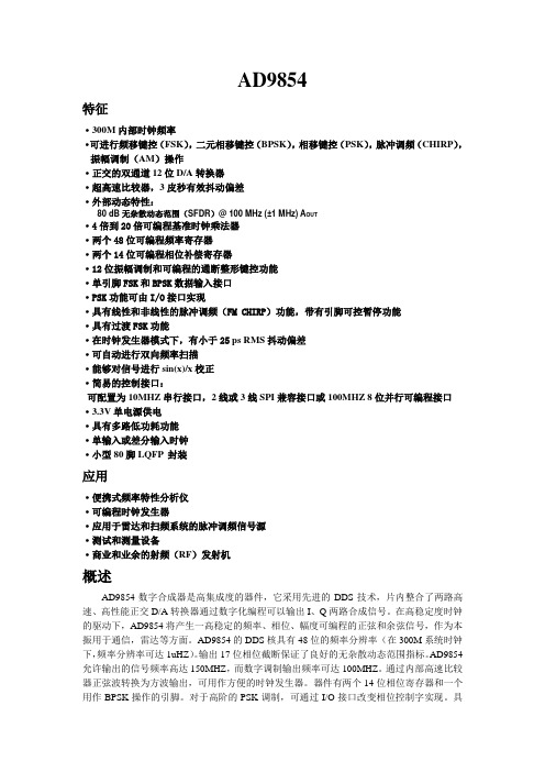
AD9854特征·300M内部时钟频率·可进行频移键控(FSK),二元相移键控(BPSK),相移键控(PSK),脉冲调频(CHIRP),振幅调制(AM)操作·正交的双通道12位D/A转换器·超高速比较器,3皮秒有效抖动偏差·外部动态特性:80 dB无杂散动态范围(SFDR)@ 100 MHz (±1 MHz) A OUT·4倍到20倍可编程基准时钟乘法器·两个48位可编程频率寄存器·两个14位可编程相位补偿寄存器·12位振幅调制和可编程的通断整形键控功能·单引脚FSK和BPSK数据输入接口·PSK功能可由I/O接口实现·具有线性和非线性的脉冲调频(FM CHIRP)功能,带有引脚可控暂停功能·具有过渡FSK功能·在时钟发生器模式下,有小于25 ps RMS抖动偏差·可自动进行双向频率扫描·能够对信号进行sin(x)/x校正·简易的控制接口:可配置为10MHZ串行接口,2线或3线SPI兼容接口或100MHZ 8位并行可编程接口·3.3V单电源供电·具有多路低功耗功能·单输入或差分输入时钟·小型80脚LQFP 封装应用·便携式频率特性分析仪·可编程时钟发生器·应用于雷达和扫频系统的脉冲调频信号源·测试和测量设备·商业和业余的射频(RF)发射机概述AD9854数字合成器是高集成度的器件,它采用先进的DDS技术,片内整合了两路高速、高性能正交D/A转换器通过数字化编程可以输出I、Q两路合成信号。
在高稳定度时钟的驱动下,AD9854将产生一高稳定的频率、相位、幅度可编程的正弦和余弦信号,作为本振用于通信,雷达等方面。
AD9854的DDS核具有48位的频率分辨率(在300M系统时钟下,频率分辨率可达1uHZ)。
CH412 中文手册说明书

ESD 保护芯片CH412中文手册 版本:1B 1、概述CH412是四路ESD 保护二极管阵列,能够承受IEC 61000-4-2规定的最高±15KV 人体模型、±8KV 接触放电以及±15KV 气隙放电的ESD 脉冲,用于电子产品对外接口中的高速信号和差分信号以及通用信号的ESD 保护。
CH412K 提供4通道低电容二极管保护和TVS 瞬态电压抑制器箝位,适用于高速和中低速信号,可以用于USB 超速、高速和全速以及低速信号保护。
CH412Z 提供4通道TVS 瞬态电压抑制器箝位,适用于中低速信号,可以用于USB 全速和低速信号保护。
CH412K CH412Z2、特点● 支持±15KV 人体模型HBM 。
● 支持±8KV 接触放电。
● 支持±15KV 气隙放电。
● CH412K :内部4路独立箝位二极管,典型值1pF 的低输入电容,适用于高速和中低速信号。
● CH412Z :内部4路TVS 箝位保护,典型值20pF 的输入电容,适用于中低速信号。
● 采用SOT 小体积晶体管级贴片无铅封装,兼容RoHS 。
3、封装封装形式 塑体宽度 引脚间距 封装说明 订货型号 SOT363 1.25mm 49mil 0.65mm 26mil 小型6脚贴片 CH412K SOT353 1.25mm 49mil 0.65mm 26mil 小型5脚贴片 CH412Z 注:1、封装体积较小,正面印字仅有代号而不含全部型号,例如CH412Z 代号是12。
2、盘装,每盘整包装数量为3000只,可以零售,但是零售时不会逐个清点数量。
IO4 IO3 IO3 VCC IO44、型号CH412B已经停产,请换用CH412K,多出的两个通道可以悬空或并联(低速时)。
4、引脚CH412K 引脚号CH412Z引脚号引脚名称类型引脚说明2 2 GND 电源公共接地端,必须直接连接到全局地5 无VCC 电源正电源端,必须靠近引脚对GND连接0.1μF电容,用于USB信号保护时通常为3.3V(或者5V),用于其它信号须同被保护芯片的电源电压(2V~5V)1,3,4,6 1,3,4,5 IO1~IO4 信号ESD保护通道,与被保护芯片的信号引脚并联5、应用说明CH412设计用来与被保护芯片内置的ESD保护一起工作。
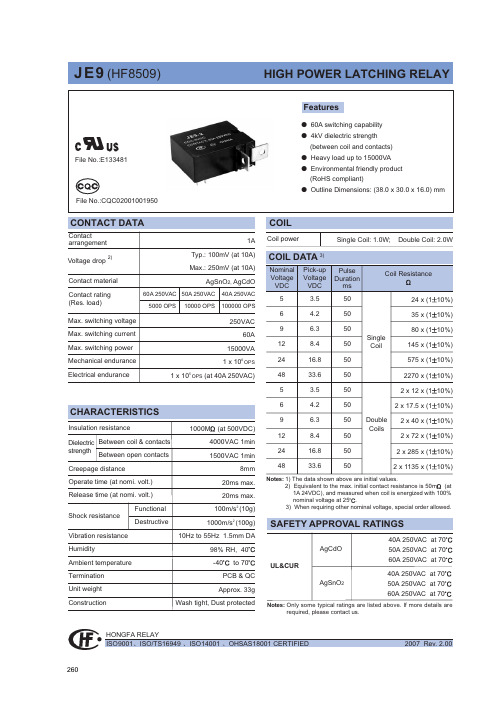
JE9348HSR1中文资料
7;5A<6?@>?FEL<G B8I:?@D>G<B8M:EDI8:I ;8I8:E@B/IG=:5>07;6KF>27KF>26KF>28/Chmmhf ob^p0Onmebg^Ebf^glbhglEJIB@D<;@C<DH@EDH+L@G@D>;@8>G8C 8D;F:9E8G;B8MEJIUgbm?ffPDC LZrhnm 70Ghk ab`a bgknla ehZ]pbma ma^lm^Z]r2lmZm^\nkk^gm h_e^ll maZg 95B1ie^Zl^\ahhl^mri^J380Ug]^k ma^Zf[b^g\^pbma ]Zg`^khnl `Zl ebd^I 7S1SO 7hk NO 71pZla mb`am mri^bl k^\hff^g]^]@ie^Zl^m^lm ma^k^eZr bg k^Ze Ziieb\Zmbhgl3J_ma^Zf[b^g\^Zeehpl1]nlm ikhm^\m^]bl ik^_^k^gmbZeer k^\hff^g]^]390K F>bl Zg ^gobkhgf^gmZe _kb^g]er ikh]n\m3Pe^Zl^fZkdZ li^\bZe \h]^/:::0hk /::60pa^g hk]^kbg`3/::60lmZg]l RhIS \hfiebZgm pbma DZ]fbnf \hgmZ\m@/:::0lmZg]l _hk RhIS \hfiebZgm pbma DZ]fbnf2_k^^\hgmZ\m3DZ^Q]7W^e]bg`ib\mnk^l _hk KF>pbma mpblmbg`\hii^k pbk^3Pe^Zl^lahp p^e]bg`lmre^/B mh J 0Zg]ma^e^g`ma h_pbk^l pa^g hk]^kbg`3Pe^Zl^fZkdma^e^g`ma h_^Z\a pbk^_khf e^_m mh kb`am b_ma^e^g`ma bl ]b__^k^gm3/Chmmhf ob^p0H<I~OZY^NO^OWZ]Q*G<H<I~OZY^NO^Z[QY*SFTRFSFT SFTRFSFT Mhngmbg`T^kfbgZe Mhngmbg`T^kfbgZeMhngmbg`T^kfbgZe/\hgmZ\m \ehl^0/\hgmZ\m hi^g0/\hgmZ\m \ehl^0/\hgmZ\m hi^g0SFTRFSFT Mhngmbg`T^kfbgZe/\hgmZ\m \ehl^0/\hgmZ\m hi^g0SFTRFSFT Mhngmbg`T^kfbgZe/\hgmZ\m \ehl^0/\hgmZ\m hi^g0Mhngmbg`T^kfbgZe Mhngmbg`T^kfbgZeMhngmbg`T^kfbgZeH<I~OZY^NO^OWZ]Q*H<I~OZY^NO^OWZ]Q*H<I~OZY^NO^OWZ]Q*H<I~OZY^NO^Z[QY*H<I~OZY^NO^Z[QY*H<I~OZY^NO^Z[QY*KF>26KF>27KF>28KF>261R6KF>271R7KF>281R8KF>281R:KF>281R97;7Wbkbg`EbZ`kZf EJIB@D<;@C<DH@EDH+L@G@D>;@8>G8C 8D;F:9E8G;B8MEJIUgbm?ffPhlbmbo^iheZkbmrN^`Zmbo^iheZkbmrN^`Zmbo^iheZkbmr7;8=04/aA61RA;5501=05/aA71RA8550=06/aA61RA<5501=1-/aA71RA8:50=./aA61RA:5501=//aA71RA7:50=0/aA61RA:5501=1/aA71RA7:50=6/aA61RA8<501=.-/aA71RA6=:0=../aA61RA<5501=.//aA71RA8:50=.4/aA61RA;;501=.5/aA71RA8850=.6/aA61RA8;501=/-/aA71RA6=50=/2/aA61RA8=501=/3/aA71RA6>50=/4/aA61RA:5501=/5/aA71RA7:50=00/aA61RA95501=01/aA71RA7550=02/aA61RA;5501=03/aA71RA8550Smre^h_fZg`Zgbg langmDZ^Q]7Smre^G6mh G991ma^mab\dg^ll h_langm?aA6hk aA71R?k^lblmZg\^h_langm [^mp^^g B2C i v 1f 65,j=2=.0/aA61RA8>501=.1/aA71RA6>:0=/./aA61RA9:501=///aA71RA77:0=/6/aA61RA:5501=0-/aA71RA7:50=4/aA61RA8;501=5/aA71RA6=50=.2/aA61RA8:501=.3/aA71RA6<:0=/0/aA61RA:5501=/1/aA71RA7:50=0./aA61RA=5501=0//aA71RA9550EJIB@D<;@C<DH@EDH+L@G@D>;@8>G8C 8D;F:9E8G;B8MEJIUgbm?ffEbl\eZbf^kTabl ]ZmZla^^m bl _hk ma^\nlmhf^klx k^_^k^g\^3Bee ma^li^\b_b\Zmbhgl Zk^ln[c^\m mh \aZg`^pbmahnm ghmb\^3W^\hne]ghm ^oZenZm^Zee ma^i^k_hkfZg\^Zg]Zee ma^iZkZf^m^kl _hk ^o^kr ihllb[e^Ziieb\Zmbhg3Tanl ma^nl^k lahne][^bg Z kb`am ihlbmbhg mh \ahhl^ma^lnbmZ[e^ikh]n\m _hk ma^bk hpg Ziieb\Zmbhg3J_ma^k^bl Zgr jn^kr1ie^Zl^\hgmZ\m Ihg`_Z _hk ma^m^\agb\Ze l^kob\^3Ihp^o^k1bm bl ma^nl^kxl k^lihglb[bebmr mh ]^m^kfbg^pab\a ikh]n\m lahne][^nl^]hger3t XbZf^g Ihg`_Z Fe^\mkhZ\hnlmb\Dh31Lm]3Bee kb`aml h_Ihg`_Z Zk^k^l^ko^]37;9DZ^UOQ63R^eZr bl hg ma^yl^mz lmZmnl pa^g [^bg`k^e^Zl^]_khf lmh\d1pbma ma^\hglb]^kZmbhg h_lah\d kbl^g _khf mkZglbm Zg]k^eZr fhngmbg`1k^eZr phne][^\aZg`^]mh yk^l^mz lmZmnl1ma^k^_hk^1pa^g Ziieb\Zmbhg /\hgg^\mbg`ma^ihp^k lniier01ie^Zl^k^l^m ma^k^eZr mh yl^mz hk yk^l^mz lmZmnl hg k^jn^lm373Jg hk]^k mh fZbgmZbg yl^mz hk yk^l^mz lmZmnl1^g^k`bs^]ohemZ`^mh \hbe lahne]k^Z\a ma^kZm^]ohemZ`^1bfinel^pb]ma lahne][^:mbf^l fhk^maZg yl^mz hk yk^l^mz mbf^3Eh ghm ^g^k`bs^ohemZ`^mh yl^mz \hbe Zg]yk^l^mz \hbe lbfnemZg^hnler3Bg]Zelh ehg`^g^k`bs^]mbf^/fhk^maZg 6fbg0lahne][^Zohb]^]383Ta^m^kfbgZel h_k^eZr pbmahnm mpblm^]\hii^k pbk^\Zg ghm [^mbg2lhe]^k^]1\Zg ghm [^fho^]pbee_neer1fhk^ho^k mph m^kfbgZel \Zg ghm [^_bq^]Zm ma^lZf^mbf^3Smre^5:;k BAw937Smre^5:;26k BAw:37Smre^5<;k BAw937Smre^5<;26k BAw:37Smre^5<<k BAw937Smre^5<<26k BAw:37Smre^5<<27k BAw;37Dhgg^mhk lmre^Trib\Ze langm \hgg^\mbhg pZrlDZ^Q]7W^\Zg fZd^li^\bZe \hgg^\mbhg Z\\hk]bg`mh \nlmhkf^k.l k^jnbk^f^gm3Pe^Zl^ikhob]^nl pbmama^]kZpbg`1Zg]langm li^\b_b\Zmbhg Zg]\hgg^\mhk.l li^\b_b\Zmbbhg3GQXN\V760Jg \Zl^h_gh mhe^kZg\^lahpg bg hnmebg^]bf^glbhg?hnmebg^]bf^glbhg g 6ff1mhe^kZg\^lahne][^u537ff@hnmebg^]bf^glbhg l 6ffZg]g :ff1mhe^kZg\^lahne][^u538ff@hnmebg^]bf^glbhg l :ff1mhe^kZg\^lahne][^u539ff370Ta^mhe^kZg\^pbmahnm bg]b\Zmbg`_hk PDC eZrhnm bl ZepZrl u536ff3EJIB@D<;@C<DH@EDH+L@G@D>;@8>G8C 8D;F:9E8G;B8MEJIUgbm?ffSmre^h_fZg`Zgbg langmDZ^Q]7Smre^G6mh G991ma^mab\dg^ll h_langm?aA6hk aA71R?k^lblmZg\^h_langm [^mp^^g B2C i v 1f 65,j=1./aA61RA99501=1//aA71RA7750=10/aA61RA;5501=11/aA71RA8550。
ATEN UH-9124 说明书
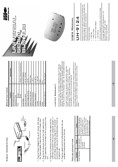
Reset the unit by unplugging the Upstream cable from the computer’s USB port and then reinserting it. If you have daisy chained hubs, do this on the hub that connects directly to the computer.
© Copyright 2000 ATEN International Co., Ltd. Manual Part No. PAPE-1121-500 Printed in Taiwan 06/2000
All brand names and trademarks are the registered property of their respective owners.
The UH-9124 is a four port USB hub that serves as a cable concentrator and bridge between the computer’s USB Host Controller, and USB peripheral devices attached to the system.
Operating Temperature
Storage Temperature
Humidity
Housing
Weight
Dimensions (L x W x H)
Specification
1 4 1 4 (Status / Overcurrent Detection) Bus/Self Powered +6V DC (100mW) +5V DC 500mA (max) 5 - 40o C -20 - 60o C 0 - 80% RH Plastic 80 g 95 x 64 x 22 mm
高性能硅门CMOS74HC04芯片说明书
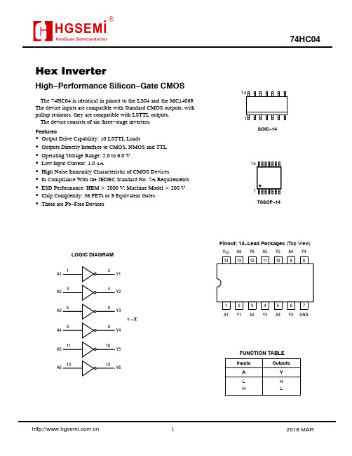
Hex InverterHigh −Performance Silicon −Gate CMOSThe 74HC04 is identical in pinout to the LS04 and the MC14069.The device inputs are compatible with Standard CMOS outputs; with pullup resistors, they are compatible with LSTTL outputs.The device consists of six three −stage inverters.Features•Output Drive Capability: 10 LSTTL Loads•Outputs Directly Interface to CMOS, NMOS and TTL •Operating V oltage Range: 2.0 to 6.0 V •Low Input Current: 1.0 m A•High Noise Immunity Characteristic of CMOS Devices•In Compliance With the JEDEC Standard No. 7A Requirements •ESD Performance: HBM > 2000 V; Machine Model > 200 V •Chip Complexity: 36 FETs or 9 Equivalent Gates •These are Pb −Free DevicesLOGIC DIAGRAMY1A1A2A3A4A5A6Y2Y3Y4Y5Y6Y = APinout: 14−Lead Packages (Top View)1314121110982134567V CC A6Y6A5Y5A4Y4A1Y1A2Y2A3Y3GNDTSSOP −14SOIC −14114114L HFUNCTION TABLEInputsOutputsA H LYMAXIMUM RATINGSSymbol Parameter Value Unit V CC DC Supply Voltage (Referenced to GND)– 0.5 to + 7.0V V in DC Input Voltage (Referenced to GND)– 0.5 to V CC + 0.5V V out DC Output Voltage (Referenced to GND)– 0.5 to V CC + 0.5VI in DC Input Current, per Pin±20mAI out DC Output Current, per Pin±25mAI CC DC Supply Current, V CC and GND Pins±50mAP D Power Dissipation in Still Air,SOIC Package†TSSOP Package†500450mWT stg Storage Temperature– 65 to + 150_C T L Lead Temperature, 1 mm from Case for 10 SecondsSOIC or TSSOP Package260_CStresses exceeding Maximum Ratings may damage the device. Maximum Ratings are stress ratings only. Functional operation above the Recommended Operating Conditions is not implied. Extended exposure to stresses above the Recommended Operating Conditions may affect device reliability.*This device contains protection circuitry to guard against damage due to high static voltages or electric fields. However, precautions must be taken to avoid applications of any voltage higher than maximum rated voltages to this high−impedance circuit. For proper operation, V in and V out should be constrained to the range GND v (V in or V out) v V CC. Unused inputs must always be tied to an appropriate logic voltage level (e.g., either GND or V CC). Unused outputs must be left open.†Derating−SOIC Package: – 7 mW/_C from 65_ to 125_CTSSOP Package: − 6.1 mW/_C from 65_ to 125_CFor high frequency or heavy load considerations, see Chapter 2 of the ON Semiconductor High−Speed CMOS Data Book (DL129/D).RECOMMENDED OPERATING CONDITIONSSymbol Parameter Min Max Unit V CC DC Supply Voltage (Referenced to GND) 2.0 6.0VV in, V out DC Input Voltage, Output Voltage (Referenced to GND)0V CC V T A Operating Temperature, All Package Types– 55+ 125_Ct r, t f Input Rise and Fall Time V CC = 2.0 V (Figure 1)V CC = 4.5 VV CC = 6.0 V 01000500400nsDC CHARACTERISTICS(Voltages Referenced to GND)V CC (V)Guaranteed LimitSymbol Parameter Condition−55 to 25°C≤85°C≤125°C UnitV IH Minimum High−Level InputVoltage V out = 0.1V or V CC−0.1V|I out| ≤ 20m A2.03.04.56.01.502.103.154.201.502.103.154.201.502.103.154.20VV IL Maximum Low−Level InputVoltage V out = 0.1V or V CC− 0.1V|I out| ≤ 20m A2.03.04.56.00.500.901.351.800.500.901.351.800.500.901.351.80VV OH Minimum High−Level OutputVoltage V in = V IH or V IL|I out| ≤ 20m A2.04.56.01.94.45.91.94.45.91.94.45.9V V in =V IH or V IL|I out| ≤ 2.4mA|I out| ≤ 4.0mA |I out| ≤ 5.2mA 3.04.56.02.483.985.482.343.845.342.203.705.20V OL Maximum Low−Level OutputVoltage V in = V IH or V IL|I out| ≤ 20m A2.04.56.00.10.10.10.10.10.10.10.10.1VV in = V IH or V IL|I out| ≤ 2.4mA|I out| ≤ 4.0mA|I out| ≤ 5.2mA3.04.56.00.260.260.260.330.330.330.400.400.40I in Maximum Input LeakageCurrentV in = V CC or GND 6.0±0.1±1.0±1.0m AI CC Maximum Quiescent SupplyCurrent (per Package)V in = V CC or GNDI out = 0m A6.0 2.02040m ANOTE:Information on typical parametric values can be found in Chapter 2 of the ON Semiconductor High−Speed CMOS Data Book (DL129/D). AC CHARACTERISTICS(C L = 50pF, Input t r = t f = 6ns)V CC (V)Guaranteed LimitSymbol Parameter−55 to 25°C≤85°C≤125°C Unitt PLH, t PHL Maximum Propagation Delay, Input A or B to Output Y(Figures 1 and 2)2.03.04.56.07530151395401916110552219nst TLH, t THL Maximum Output Transition Time, Any Output(Figures 1 and 2)2.03.04.56.07527151395321916110362219nsC in Maximum Input Capacitance101010pF NOTE:For propagation delays with loads other than 50 pF, and information on typical parametric values, see Chapter 2 of the ON Semiconductor High−Speed CMOS Data Book (DL129/D).C PD Power Dissipation Capacitance (Per Inverter)*Typical @ 25°C, V CC = 5.0 VpF20*Used to determine the no−load dynamic power consumption: P D = C PD V CC2f + I CC V CC. For load considerations, see Chapter 2 of the ON Semiconductor High−Speed CMOS Data Book (DL129/D).Figure 1. Switching WaveformsGNDV CCOUTPUT YINPUT AC L **Includes all probe and jig capacitanceTESTFigure 2. Test CircuitYA Figure 3. Expanded Logic Diagram(1/6 of the Device Shown)。
FPGA可编程逻辑器件芯片EP4CE40F29I7中文规格书

Chapter 4:DSP Blocks in Arria II DevicesDSP Block Resource Descriptions All DSP block registers are triggered by the positive edge of the clock signal and arecleared after power up. Each multiplier operand can feed an input register or feeddirectly to the multiplier, bypassing the input registers. The clock[3..0], ena[3..0],and aclr[3..0]DSP block signals control the input registers in the DSP block.Every DSP block has nine 18-bit data input register banks per half-DSP block. Everyhalf-DSP block has the option to use the eight data register banks as inputs to the fourmultipliers. The special ninth register bank is a delay register required by modes thatuse both the cascade and chainout features of the DSP block to balance the latencyrequirements when using the chained cascade feature. A feature of the input registerbank is to support a tap delay line. Therefore, you can drive the top leg of themultiplier input (A) from general routing or from the cascade chain, as shown inFigure4–6.At compile time, you must select the incoming data for multiplier input (A) fromeither general routing or from the cascade chain. In cascade mode, the dedicated shiftoutputs from one multiplier block directly feeds input registers of the adjacentmultiplier below it (in the same half-DSP block) or the first multiplier in the nexthalf-DSP block, to form an 8-tap shift register chain per DSP block. The DSP block canincrease the length of the shift register chain by cascading to the lower DSP blocks.The dedicated shift register chain spans a single column, but you can implementlonger shift register chains requiring multiple columns with the regular FPGA routingresources.Shift registers are useful in DSP functions such as FIR filters. When implementing an18×18 or smaller width multiplier, you do not require external logic to create the shiftregister chain because the input shift registers are internal to the DSP block. Thisimplementation significantly reduces the logical element (LE) resources required,avoids routing congestion, and results in predictable timing.The first multiplier in every half-DSP block (top- and bottom-half) has a multiplexerfor the first multiplier B-input (lower-leg input) register to select between generalrouting and loopback, as shown in Figure4–5 on page4–8. In loopback mode, themost significant 18-bit registered outputs are connected as feedback to the multiplierinput of the first top multiplier in each half-DSP block. Loopback modes are used byrecursive filters where the previous output is required to compute the current output.Loopback mode is described in detail in “Two-Multiplier Adder Sum Mode” onpage4–20.Table4–3 lists the summary of input register modes for the DSP block.Table4–3.Input Register Modes for Arria II DevicesRegister Input Mode (1)9×912×1218×1836×36Double Parallel input v v v v vShift register input (2)——v——Loopback input (3)——v——Notes to Table4–3:(1)The multiplier operand input word lengths are statically configured at compile time.(2)Available only on the A-operand.(3)Only one loopback input is allowed per half block. For details, refer to Figure4–14 on page4–21.Design Considerations Figure3–21 shows sample functional waveforms of same-port read-during-writebehavior in new data mode.Figure3–21.M9K and M144K Blocks Same Port Read-During Write: New Data ModeFigure3–22 shows sample functional waveforms of same-port read-during-writebehavior in old data mode.Figure3–22.M9K and M144K Blocks Same Port Read-During-Write: Old Data ModeFor MLABs, the output of the MLABs can only be set to don’t care in same-portread-during-write mode. In this mode, the output of the MLABs is unknown during awrite cycle. There is a window near the falling edge of the clock during which theoutput is unknown. Prior to that window, “old data” is read out; after that window,“new data” is seen at the output.DSP Block OverviewDSP Block OverviewArria II GX devices have two to four columns of DSP blocks, while Arria II GZdevices have two to seven columns of DSP blocks. These DSP blocks implementmultiplication, multiply-add, multiply-accumulate (MAC), and dynamic shiftfunctions. Architectural highlights of the Arria II DSP block include:■High-performance, power-optimized, fully registered, and pipelinedmultiplication operations■Natively supported 9-bit, 12-bit, 18-bit, and 36-bit word lengths■Natively supported 18-bit complex multiplications■Efficiently supported floating-point arithmetic formats (24 bits for single precision and 53 bits for double precision)■Signed and unsigned input support■Built-in addition, subtraction, and accumulation units to efficiently combinemultiplication results■Cascading 18-bit input bus to form tap-delay line for filtering applications■Cascading 44-bit output bus to propagate output results from one block to the next block without external logic support■Rich and flexible arithmetic rounding and saturation units■Efficient barrel shifter support■Loopback capability to support adaptive filtering。
FPGA可编程逻辑器件芯片EP4CE115F29I8N中文规格书

P IPELINED V ISION P ROCESSOR (PVP)P ROGRAMMING M ODEL•If the PVP_THCn_CFG.STATWCNT field =18, the PVP_THCn_HFCNT_STAT and PVP_THCn_HCNT0_STAT to PVP_THCn_HCNT15_STAT, and PVP_THCn_RREP_STAT registers are sent.The STATWCNT field of all processing blocks other than IPFs and THCs are reserved and must be initialized with zero values.Status reports only output status registers. There is no programmable offset as in the case of block config-uration.Block Status StructureWhen a processing block contributes to a status report, its data words are headed by a block status header (BSH). The BSH is similar to the block configuration header (BCH). It consists of the block ID value and also has a word count field. The latter mirrors the STATWCNT value as specified in the block configuration register. Unlike BCHs the BSHs do not have an offset field. The entity of Block Status Header and respec-tive status words is called Block Status Structure (BSS). A BSS always consists of STATWCNT+1 32-bit words.A status report consists of a list of block status structures. Such a list is referred to as block status list (BSL).An example is shown in the BSL example figure. This example assumes that both threshold blocks are configured in camera pipe mode. IPF0 and THC0 blocks are configured to send status to the report. The THC1 block is not configured to send status, so its PVP_THCn_CFG.STATWCNT field =0.Figure 30-70:BSL ExampleThe input formatters make always the first entries in the block status list. If both threshold blocks are enabled in the same pipe, the one that comes first is closer to the IPFn in the pipe arrangement. In case the pipe configuration is not known, the block ID in the BSHs can be consulted.Although it is not a hardware requirement, it is recommended that the work unit transfer count of the DMA associated with the status output matches the number of 32-bit words in the BSL.ADSP-BF60X B LACKFIN P ROCESSOR H ARDWARE R EFERENCEP IPELINED V ISION P ROCESSOR (PVP)ADSP-BF60X PVP R EGISTER D ESCRIPTIONSTable 30-49:ADSP-BF60x PVP Register List (Continued)Name DescriptionPVP_ACU_CFG ACU ConfigurationPVP_ACU_CTL ACU ControlPVP_ACU_OFFSET ACU SUM ConstantPVP_ACU_FACTOR ACU PROD ConstantPVP_ACU_SHIFT ACU Shift ConstantPVP_ACU_MIN ACU Lower Sat Threshold MinPVP_ACU_MAX ACU Upper Sat Threshold MaxPVP_UDS_CFG UDS ConfigurationPVP_UDS_CTL UDS ControlPVP_UDS_OHCNT UDS Output HCNTPVP_UDS_OVCNT UDS Output VCNTPVP_UDS_HAVG UDS HAVGPVP_UDS_VAVG UDS V AVGPVP_IPF0_CFG IPF0 (Camera Pipe) ConfigurationPVP_IPFn_PIPECTL IPFn (Camera/Memory Pipe) Pipe ControlPVP_IPFn_CTL IPFn (Camera/Memory Pipe) ControlPVP_IPFn_TAG IPFn (Camera/Memory Pipe) TAG ValuePVP_IPFn_FCNT IPFn (Camera/Memory Pipe) Frame CountPVP_IPFn_HCNT IPFn (Camera/Memory Pipe) Horizontal CountPVP_IPFn_VCNT IPFn (Camera/Memory Pipe) Vertical CountPVP_IPF0_HPOS IPF0 (Camera Pipe) Horizontal PositionPVP_IPF0_VPOS IPF0 (Camera Pipe) Vertical PositionADSP-BF60X B LACKFIN P ROCESSOR H ARDWARE R EFERENCEP IPELINED V ISION P ROCESSOR (PVP)ADSP-BF60X PVP R EGISTER D ESCRIPTIONSTable 30-49:ADSP-BF60x PVP Register List (Continued)Name DescriptionPVP_THCn_HFCNT THCn Histogram Frame CountPVP_THCn_RMAXREP THCn Max RLE ReportsPVP_THCn_CMINVAL THCn Min Clip ValuePVP_THCn_CMINTH THCn Clip Min ThresholdPVP_THCn_CMAXTH THCn Clip Max ThresholdPVP_THCn_CMAXVAL THCn Max Clip ValuePVP_THCn_TH0THCn Threshold Value 0PVP_THCn_TH1THCn Threshold Value 1PVP_THCn_TH2THCn Threshold Value 2PVP_THCn_TH3THCn Threshold Value 3PVP_THCn_TH4THCn Threshold Value 4PVP_THCn_TH5THCn Threshold Value 5PVP_THCn_TH6THCn Threshold Value 6PVP_THCn_TH7THCn Threshold Value 7PVP_THCn_TH8THCn Threshold Value 8PVP_THCn_TH9THCn Threshold Value 9PVP_THCn_TH10THCn Threshold Value 10PVP_THCn_TH11THCn Threshold Value 11PVP_THCn_TH12THCn Threshold Value 12PVP_THCn_TH13THCn Threshold Value 13PVP_THCn_TH14THCn Threshold Value 14PVP_THCn_TH15THCn Threshold Value 15ADSP-BF60X B LACKFIN P ROCESSOR H ARDWARE R EFERENCE。
RM9124-800F中文资料
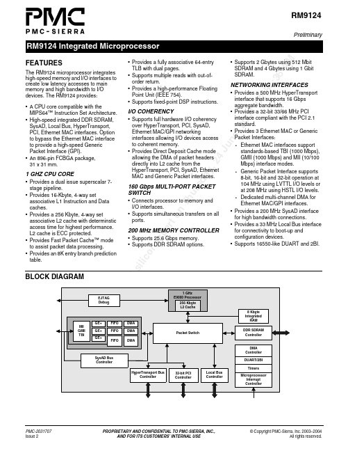
il i c o ne xp er to n Th u r sd a y , 24 Ju ne , 200402:54:36A MRM9124PreliminaryRM9124 Integrated MicroprocessorPMC-2031707 PROPRIETARY AND CONFIDENTIAL TO PMC -SIERRA, INC.,© Copyright PMC-Sierra, Inc. 2003–2004Issue 2AND FOR ITS CUSTOMERS’ INTERNAL USEAll rights reserved.FEATURESThe RM9124 microprocessor integrates high-speed memory and I/O interfaces to create low latency accesses to main memory and high bandwidth to I/O devices. The RM9124 provides:•A CPU core compatible with theMIPS64™ Instruction Set Architecture.•High-speed integrated DDR SDRAM, SysAD, Local Bus, HyperTransport, PCI, Ethernet MAC interfaces. Option to bypass the Ethernet MAC interface to provide a high-speed Generic Packet Interface (GPI).•An 896-pin FCBGA package, 31x 31mm.1 GHZ CPU CORE•Provides a dual issue superscalar 7-stage pipeline.•Provides 16-Kbyte, 4-way setassociative L1 Instruction and Data caches.•Provides a 256 Kbyte, 4-way setassociative L2 cache with determinstic access time for highest performance. L2 cache is ECC protected.•Provides Fast Packet Cache™ mode to assist packet data processing.•Provides an 8K entry branch prediction table.•Provides a fully associative 64-entry TLB with dual pages.•Supports multiple reads with out-of-order return.•Provides a high-performance Floating Point Unit (IEEE 754).•Supports fixed-point DSP instructions.I/O COHERENCY•Supports full hardware I/O coherency over HyperTransport, PCI, SysAD, Ethernet MAC/GPI networkinginterfaces allowing I/O devices access to coherent memory.•Provides Direct Deposit Cache mode allowing the DMA of packet headers directly into L2 cache from theHyperTransport, PCI, SysAD, Ethernet MAC and Generic Packet interfaces.160 Gbps MULTI-PORT PACKET SWITCH•Connects processor to memory and I/O interfaces.•Supports simultaneous transfers on all ports.200 MHz MEMORY CONTROLLER•Supports 25.6 Gbps memory.•Supports DDR SDRAM options.•Supports 2 Gbytes using 512 Mbit SDRAM and 4 Gbytes using 1 Gbit SDRAM.NETWORKING INTERFACES•Provides a 500 MHz HyperTransport interface that supports 16 Gbps aggregate bandwidth.•Provides a 32-bit 33/66 MHz PCI interface compliant with the PCI 2.1 standard.•Provides 3 Ethernet MAC or Generic Packet Interfaces:•Ethernet MAC interfaces support standards-based TBI (1000 Mbps), GMII (1000 Mbps) and MII (10/100 Mbps) interface modes.•Generic Packet Interface supports 8-bit, 16-bit and 32-bit operation at 104 MHz using LVTTL I/O levels or at 208 MHz using HSTL I/O levels.•Dedicated multi-channel DMA for Ethernet MAC/GPI interfaces.•Provides a 200 MHz SysAD interface for high bandwidth connections.•Provides a 33 MHz Local Bus interface for connectivity to boot-up and configuration devices.•Supports 16550-like DUART and 2BI.D ow n lu r sd a y , 24 Ju ne , 200402:54:36A MHead Office:PMC-Sierra, Inc.8555 Baxter PlaceBurnaby, B.C. V5A 4V7CanadaTel: 1.604.415.6000Fax: 1.604.415.6200Integrated MicroprocessorTo order documentation, send email to:document@ or contact the head office,Attn: Document CoordinatorPMC-2031707 (P2)© Copyright PMC-Sierra, Inc. 2003–2004. All rights reserved.For a complete list of PMC-Sierra’s trademarks and registered trademarks, visit: /legal/PROPRIETARY AND CONFIDENTIAL TO PMC-SIERRA, INC., AND FOR ITS CUSTOMERS’ INTERNAL USERM9124All product documentation is available on our web site at: For corporate information,send email to:info@ADDITIONAL FEATURES•Provides 8 Kbytes integrated low latency scratch RAM.•Provides an integrated on-chip EJTAG Debug module to ensure easydebugging of hardware and software and a Trace Buffer to allow tracing instruction execution for debugging.•Provides a flexible 4-channel DMA control architecture providing DMA to any block, scatter/gather support, and external DMA request support.•Provides a vectored, prioritized interrupt controller that supports:•256 prioritized interrupts.•Programmable interrupt delivery modes, for processor as well as external and HyperTransport or PCI interrupts.•Provides 2 integrated Performance Counters:•Counts over 30 processor events.•Enables full characterization and analysis of application software.•Provides 6 addtional timers for Watchdog and general purpose timing for software.THIRD PARTY SUPPORTOPERATING SYSTEMS•SMP Linux.•VxWorks MP from Wind River.EJTAG EMULATORS•Wind River.•Corelis.EVALUATION BOARDS•ATX Evaluation Board.COMPANION CHIPS•Wide range of companion chips available to interface with SysAD, HyperTransport, and PCI.APPLICATIONS•Enterprise LAN Switches and Routers.•Enterprise and Service Provider WAN Switches and Routers.•Multiservice Access Switches and Routers.•High-end Server Network Interface Cards.•L4 – L7 Network Services Cards.•Wireless Base Stations.•Storage Networking.•Security.。
工控机技术资料

串 口 … … … … … … … … … … … … … … … … … … … … … … … … … … … … … … … … … … … 9
并 口 … … … … … … … … … … … … … … … … … … … … … … … … … … … … … … … … … … … 10
接 口 功 能 介 绍 … … … … … … … … … … … … … … … … … … … … … … … … … … … … … … … 5
功 能 示 意 图 … … … … … … … … … … … … … … … … … … … … … … … … … … … … … … 5
技术支持
用户可通过以下途径获得思泰基电脑的相关技术支持:
表 1.思泰基技术支持信息
网址 http://www.seatech.sh.cn
E-mail seatech@seatech.sh.cn
电话 021-61450355/6/7/8
通讯地址 上海宜山路 1618 号综合楼四楼
CPU
采用低功耗 486CPU,并可通过跳线调节 CPU 的频率。
CRT 接口/ LCD 接口
DX-440C 同时提供 CRT/LCD 显示接口,可支持各种液晶屏。
DOC 插座
DX-440C 提供一个在板 DOC (Disk On Chip) 插座,可支持 8M~144M 的 DOC。
软驱接口
DX-440C 主板已集成标准的软驱接口于主板上。
-4-
SEATECH 产品特征
研发部
本章介绍
本章主要包括 DX-440C 详细的一些安装和配置的相关信息,主要内容有: l 接口功能介绍 l 电源 l 内存 l 串口 l 并口 l IDE 硬盘接口 l 软驱 l DOC 插座 l Utility 接口 l 总线接口;
B54LVC08RH辐射加固四路2输入与门产品使用手册说明书

Ver 1.1 辐射加固四路2输入与门产品型号:B54LVC08RH版本控制页目录一、产品概述 (1)1.1产品特点 (1)1.2产品用途及应用范围 (1)1.3免责声明 (1)二、产品工作条件 (2)2.1绝对最大额定值 (2)2.2推荐工作条件 (2)2.3 热特性参数 (2)三、封装及引出端说明 (3)3.1 引出端排列 (3)3.2 外形尺寸说明 (5)四、产品功能 (8)五、产品电特性 (8)六、应用注意事项 (10)6.1输入信号要求 (10)6.2未使用输入端的处理 (10)6.3 对电源的要求 (10)6.4输出振铃抑制 (10)6.5去耦电容的选择 (11)6.6 产品防护 (12)七、用户关注产品信息 (13)7.1 产品鉴定信息 (13)7.2 产品标识 (13)7.3 研制生产单位联系方式 (14)附录1 对应替代国外产品情况 (15)一、产品概述1.1产品特点●电源电压范围:2.0V~3.6V●输入5V兼容●输出驱动能力:24mA●支持TTL电平输入●工作温度范围:-55℃~125℃●抗总剂量能力:≥100k rad(Si)●抗单粒子锁定LET:≥75MeV•cm2/mg●ESD等级:2000V●封装形式:DIP14(B54LVC08RHD)、FP14(B54LVC08RHF)、LCC20(B54LVC08RHC)1.2产品用途及应用范围B54LVC08RH是一款辐射加固四路2输入与门电路,工作在2.0V~3.6V电源电压,具有驱动能力高、功耗低、高可靠性等特点,支持TTL信号输入。
该产品为通用逻辑电路,应用广泛。
1.3免责声明本手册版权归北京微电子技术研究所所有,并保留一切权利。
未经书面许可,任何单位、组织和个人不得将此文档中的任何部分公开、转载或以其他方式散发给第三方,否则将追究其法律责任。
本手册版本将不定期更新,请在使用本产品之前联系本单位销售部门获取本手册的最新版本。
新编俄罗斯电子器件对照手册资料

俄型号:К133ИЕ2十进制计数器说明相应国内外产品К133ИЕ2型单片TTL中规模半□中国型号导体集成电路,由四个主从触发器和附加推荐替换 SG5490A门电路组成,功能为具有清零和置9输入生产厂家 4435厂端的负沿触发异步十进制计数器。
其计数□国外型号 SN5490A (美国)长度可以是2、5、10分频。
К133ИЕ2主要参数 5490A主要参数 (T A=25℃)К133ИЕ2逻辑图和外引线排列 5490A功能表和外引线排列俄型号:К133ИЕ54位二进制计数器说明相应国内外产品К133ИЕ5型单片TTL中规模半□中国型号导体集成电路,由四个主从触发器和附加推荐替换 SG5493A门电路组成。
可组成二分频计数器和三级生产厂家 4435厂二进制计数器,具有清零输入端。
□国外型号 SN5493A (美国)AК133ИЕ5逻辑图和外引线排列 5493A功能表和外引线排列俄型号:К133ЛА28输入与非门说明相应国内外产品К133ЛА2型单片TTL小规模半□中国型号导体集成电路,功能为8输入端与非门。
推荐替换 JT5430生产厂家 4435厂□国外型号 SN5430 (美国)К133ЛА2逻辑图和外引线排列 5430逻辑图和外引线排列俄型号:К133ЛА3四2输入与非门说明相应国内外产品К133ЛА3型单片TTL小规模半□中国型号导体集成电路,由四个独立的而又完全相推荐替换 JT5400同的2输入端与非门组成。
生产厂家 4435厂□国外型号 SN5400 (美国)AК133ЛА3逻辑图和外引线排列 5400逻辑图和外引线排列说明相应国内外产品К133ЛА4型单片TTL小规模半□中国型号导体集成电路,由三个独立的而又完全相推荐替代 JT5410同的3输入端与非门组成。
生产厂家 4435厂□国外型号 SN5410 (美国)AК133ЛА4逻辑图和外引线排列* 5410逻辑图和外引线排列*注:俄产品输出脚顺序与5410不同,选用时应注意。
G9125TH4T资料
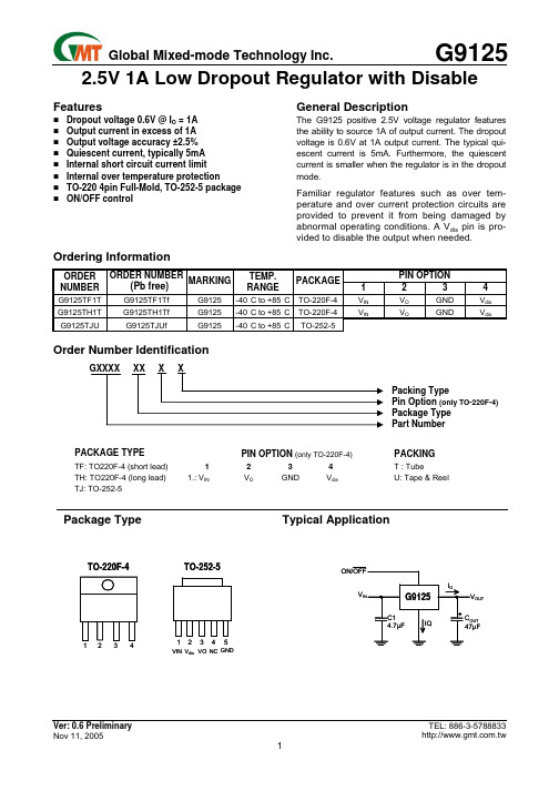
FeaturesDropout voltage 0.6V @ I O = 1A Output current in excess of 1A Output voltage accuracy ±2.5% Quiescent current, typically 5mA Internal short circuit current limit Internal over temperature protection TO-220 4pin Full-Mold, TO-252-5 package ON/OFF controlGeneral DescriptionThe G9125 positive 2.5V voltage regulator features the ability to source 1A of output current. The dropout voltage is 0.6V at 1A output current. The typical qui-escent current is 5mA. Furthermore, the quiescent current is smaller when the regulator is in the dropout mode.Familiar regulator features such as over tem-perature and over current protection circuits are provided to prevent it from being damaged by abnormal operating conditions. A V dis pin is pro-vided to disable the output when needed.Ordering InformationPIN OPTIONORDER NUMBERORDER NUMBER(Pb free) MARKINGTEMP.RANGEPACKAGE1 2 3 4G9125TF1T G9125TF1Tf G9125 -40°C to +85°C TO-220F-4V IN V O GND V dis G9125TH1T G9125TH1Tf G9125 -40°C to +85°C TO-220F-4V IN V O GND V dis G9125TJUG9125TJUfG9125-40°C to +85°CTO-252-5Order Number IdentificationTypePin Option (only TO-220F-4) TypePart NumberPACKAGE TYPEPIN OPTION (only TO-220F-4) PACKINGTF: TO220F-4 (short lead) 1 2 3 4T : TubeTH: TO220F-4 (long lead) 1.: V INV O GND V dis U: Tape & Reel TJ: TO-252-5Package Type Typical ApplicationOUT VIN V dis NC GNDVOInput Voltage (8V)V dis Voltage (8V)Power Dissipation Internally Limited (Note 2) Maximum Junction Temperature.…..…….…………150°C Storage Temperature Range……...-65°C ≤ T J≤+150°C Reflow Temperature (Soldering, 10 sec)…..……260°C Continuous Power Dissipation (T A = +25°C)TO-220 No heatsink…..………….…………………1.5W TO-220 with infinite heatsink………..…..…….……15W Thermal Resistance Junction to Ambient, (θJA)TO-252-5…………………………………………95°C/W Thermal Resistance Junction to Case, (θJC)TO-252-5…………………………………………..….8°C/W Input Voltage…………………………….………..3.6V~7V Temperature Range………….….…….-40°C ≤ T A≤85°CElectrical CharacteristicsV IN =5V, I O = 0.5A, C IN = 4.7µF, C OUT =47µF, T A = T J = 25°C unless otherwise specified [Note 3] PARAMETER SYMBOL CONDITION MIN TYP MAXUNIT Output Voltage I O=0.5A 2.44 2.5 2.56 V Line Regulation 4V < V IN < 7V, I O = 10mA --- 0.5 2 % Load Regulation 50mA < I O < 1A --- 0.5 2 % Quiescent Current V IN = 5V --- 5 10 mA Ripple Rejection fi = 120Hz, 1VP-P, I O = 100mA --- 45 --- dB Dropout Voltage I O = 1A --- 0.4 0.6 V Short Circuit Current --- 3.8 --- AOver Temperature --- 150 --- °C Disable Voltage High V disH OutputActive 2.0 --- --- V Disable Voltage Low V disL OutputDisabled --- --- 0.8 V Disable Bias Current High I disH V dis = 2.7V --- --- 20 µA Disable Bias Current Low I disL V dis = 0.4V --- --- 20 µA Note 1: Absolute Maximum Ratings are limits beyond which damage to the device may occur. Operating Conditions are conditions under which the device functions but the specifications might not be guaranteed. For guaranteed specifications and test conditions see the Electrical Characteristics.Note 2: The maximum power dissipation is a function of the maximum junction temperature, T Jmax ; total thermal resistance, θJA, and ambient temperature T A. The maximum allowable power dissipation at any ambient temperature is T jmax-T A / θJA. If this dissipation is exceeded, the die temperature will rise above 150°C and IC will go into thermal shutdown. For the TO-220 package, θJA is 60°C/W (No heat sink).Note3: Low duty pulse techniques are used during test to maintain junction temperature as close to ambient as possible.Note4: The type of output capacitor should be tantalum or aluminum.DefinitionsDropout VoltageThe input/output Voltage differential at which the regu-lator output no longer maintains regulation against fur-ther reductions in input voltage. Measured when the output drops 2% below its nominal value, dropout volt-age is affected by junction temperature, load current and minimum input supply requirements.Line RegulationThe change in output voltage for a change in input voltage. The measurement is made under conditions of low dissipation or by using pulse techniques such that average chip temperature is not significantly affected. Load RegulationThe change in output voltage for a change in load current at constant chip temperature. The measure-ment is made under conditions of low dissipation or by using pulse techniques such that average chip temperature is not significantly affected.Maximum Power Dissipation The maximum total de-vice dissipation for which the regulator will operate within specifications.Quiescent Bias CurrentCurrent which is used to operate the regulator chip and is not delivered to the load.(V IN=5V, C IN=10µF, C OUT = 10µF, T A=25°C, unless otherwise noted.)Load Transient Response Line Transient ResponseShort Circuit-Current Output NoiseDisable- ONLoad RegulationHeatsink Package DimensionTO-220F-4Recommended Minimum FootprintQuiescent Current vs. Input VoltagePower Dissipation vs. Temperature (T )TO-252-5TO-220F-4 Package (short lead)DIMENSION IN MM DIMENSION IN INCHSYMBOLMIN. NOM. MAX. MIN. NOM. MAX.A 4.42 4.57 4.72 0.174 0.180 0.186 A1 2.69 2.79 2.89 0.106 0.110 0.114A2 1.68 1.78 1.88 0.066 0.070 0.074 D 10.00 10.10 10.20 0.3940.398 0.402 E 6.85 6.95 7.05 0.269 0.273 0.278 E1 8.54 8.64 8.74 0.336 0.340 0.344 L 8.32 8.52 8.72 0.328 0.335 0.343 L1 16.56 16.66 16.76 0.652 0.656 0.660 L2 3.60 3.70 3.80 0.142 0.146 0.150 He 23.72 24.22 24.72 0.934 0.953 0.93 C ----- 0.48 ----- ----- 0.019 ----- e ----- 2.54(TYP) ----- ----- 0.1(TYP) ----- b ----- 0.635(TYP) ----- ----- 0.025(TYP) -----θ4° 7° 11°4° 7° 11°TO-220F-4 Package (long lead)DIMENSION IN MM DIMENSION IN INCHSYMBOLMIN. NOM. MAX. MIN. NOM. MAX.A 4.42 4.57 4.72 0.174 0.180 0.186A1 2.69 2.79 2.89 0.106 0.110 0.114 A2 1.68 1.78 1.88 0.066 0.070 0.074 D 10.00 10.10 10.20 0.3940.398 0.402 E 6.85 6.95 7.05 0.269 0.273 0.278 E1 8.54 8.64 8.74 0.336 0.340 0.344 L 13.15 13.35 13.55 0.518 0.526 0.533 L1 16.56 16.66 16.76 0.652 0.656 0.660 L2 3.60 3.70 3.80 0.142 0.146 0.150 He 28.44 28.94 29.44 1.119 1.139 1.159 C ----- 0.48 ----- ----- 0.019 ----- e ----- 2.54(TYP) ----- ----- 0.1(TYP) ----- b ----- 0.635(TYP) ----- ----- 0.025(TYP) -----θ4° 7° 11°4° 7° 11°bTO-252-5 (TJ) PackageMILLIMETER INCHSYMBOLMIN. MAX. MIN. MAX.A 2.19 2.38 0.086 0.094 A1 0.89 1.27 0.035 0.050 b 0.64 0.89 0.025 0.035 C 0.46 0.58 0.018 0.023 D 5.36 5.61 0.211 0.221 E 6.35 6.73 0.250 0.265 E1 5.21 5.46 0.205 0.215 e 1.27BSC 0.050BSC F 0.46 0.58 0.018 0.023 L 1.40 1.78 0.0550.070 L1 2.20 2.80 0.087 0.110 L2 1.52 2.03 0.060 0.080 H 9.40 10.40 0.370 0.410 θ 0° 4° 0° 4°Taping SpecificationPACKAGE Q’TY/TUBE Q’TY/REELTO-220F-4 50 ea ---TO-252-5 ---2,500 eaGMT Inc. does not assume any responsibility for use of any circuitry described, no circuit patent licenses are implied and GMT Inc. reserves the right at any time without notice to change said circuitry and specifications.bTO-252-5 Package OrientationFeed Direction。
D9124中文资料
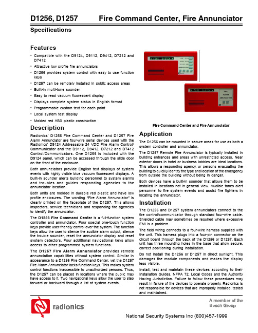
D1256, D1257
Specifications
Fire Commantor
Features
• Compatible with the D9124, D9112, D9412, D7212 and D7412 • Attractive low profile fire annunciators • D1256 provides system control with easy to use function keys • D1257 can be remotely installed in public access areas • Built-in multi-tone sounder • Easy to read vacuum fluorescent display • Displays complete system status in English format • Programmable custom text for each point • Local system test display • Molded red ABS plastic construction
Fire Command Center and Fire Annunciator
Application
The D1256 can be mounted in secure areas for use as both a system controller and annunciator. The D1257 Remote Fire Annunciator is typically installed in building entrances and areas with unrestricted access. Near exterior doors in hotel or business lobbies are ideal locations. This allows a responding agency, or persons evacuating the building to quickly identify the type and location of the emergency from outside the building without being in danger. Both devices have a built-in sounder that allows them to be installed in locations not in general view. Audible tones alert personnel to fire system events and assist fire fighters in locating the annunciator.
E24

*/
#include <intrins.h>
void PrintByte(unsigned char byte_data)
{
while( BUSY == 1 ){
}
PRINTER_DATA = byte_data;
nSTB = 0;
_nop_();
// 调整 nSTB 信号脉宽
nSTB = 1;
}
/*
SETB TR1
; 启动定时器 T1
14
炜煌针式打印机说明书
MOV SCON, #50H
; 设置串行口工作方式为异步串行口,模式 1
SETB TI
; 设置标志位,为发送数据作准备
RET
; 定义待打印数据内容
; 保存在程序段
print_content:
DB '北京炜煌科技微型打印机', 0DH, 'MicroPrinter demo', 0DH
该信号高电平时,表示打印机正“忙”不能接受数据,而当该信号
2
BUSY 出
低电平时,表示打印机“准备好”,可以接收数据)
6
BUSY 出 同 BUSY(TTL 电平时,此引脚为空引脚)
9
GND — 信号地
注: 1.“入”表示输入到打印机; 2.“出”表示从打印机输出 3.信号的逻辑电平为 TTL 电平。
2.1.3 并口例程
单片机控制打印机时汇编例程
BUSY
EQU P3.2
; 定义 BUSY 信号引脚
nSTB
EQU P3.7
; 定义 nSTB 信号引脚
ORG 0000H
6
0 . 5μS 0 . 5μS
start: main:
284049-9中文资料
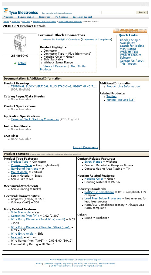
284049-9 Product DetailsHome | Customer Support | Suppliers | Site Map | Privacy Policy | Browser Support© 2008 Tyco Electronics Corporation All Rights Reserved Searc hProducts Documentation Resources My Account Customer Support Home > Products > By Type > Terminal Blocks & Strips > Product Feature Selector > Product Details284049-9Active Terminal Block ConnectorsAlways EU RoHS/ELV Compliant (Statement of Compliance)Product Highlights:l Connectorl Connector Type = Plug (right-hand)l Housing Color = Greenl Side Stackablel Without Screw FlangeView all Features | Find SimilarProductsCheck Pricing &AvailabilitySearch for ToolingView MatingProducts (15)Product FeatureSelectorContact Us AboutThis ProductQuick LinksDocumentation & Additional InformationProduct Drawings:l TERMINAL BLOCK VERTICAL PLUG STACKING, RIGHT HAND 7....(PDF, English)Catalog Pages/Data Sheets:l None AvailableProduct Specifications:l None AvailableApplication Specifications:l Terminal Block Stacking Connectors(PDF, English)Instruction Sheets:l None AvailableCAD Files:l None AvailableList all Documents Additional Information:l Product Line InformationRelated Products:l Toolingl Mating Products (15)Product Features (Please use the Product Drawing for all design activity)Product Type Features:l Product Type = Connectorl Connector Type = Plug (right-hand)l Number of Positions = 9l Mount Angle = Verticall Screw Material = Brassl Screw Size = M3Mechanical Attachment:l Screw Plating = NickelElectrical Characteristics:l Amperes (Amps.) = 15.0l Voltage (VAC) = 300Body Related Features:l Side Stackable = Yesl Centerline (mm [in]) = 7.62 [0.300]l Wire Entry Diameter (Solid Wire) (mm²) = 0.03 –2.50l Wire Entry Diameter (Stranded Wire) (mm²) =0.03 –1.50l Wire Entry Angle = Sidel Interlock = Withoutl Wire Range (mm [AWG]) = 0.05-3.00 [30-12] l Flammability Rating = UL 94V-0 Contact Related Features:l Screw Flange = Withoutl Contact Material = Phosphor Bronzel Contact Mating Area Plating = TinHousing Related Features:l Housing Color = Greenl Housing Material = PA 6.6Industry Standards:l RoHS/ELV Compliance = RoHS compliant, ELVcompliantl Lead Free Solder Processes = Not relevant forlead free processl RoHS/ELV Compliance History = Always wasRoHS compliantOther:l Brand = BuchananProvide Website Feedback | Contact Customer Support。
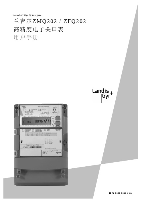
兰吉尔电度表ZQ中文用户手册(H01)
导线上存在危险电压
危险
在与电表相连接的导线上存在危险的电压。
接触带电导线,会导致严重的人身伤害或死亡。
当连接或断开与电表相连的导线时,导线不得带电。工作期间相关回路的保险丝必须取下并放到安全地方,防止其他人在不知情的情况下将其恢复。
互感器上存在危险电压
危险
E
2003年6月30日
根据安全评估(初版)进行更新.
F
2003年12月19日
根据固件H00版产品风险分析进行更新.
G
2004年3月31日
根据固件H01版功能进行更新
兰吉尔有限公司
Feldstrasse 1
CH - 6301 Zug
瑞士
电话:+41 41 724 41 41
www。landisgyr。com
在更换电池前,请把电表与测量电压或辅助电源相连接。
注意
校验铅封
在强制检验的国家,检验机构封上校验铅封,保证电表符合当地规定,测量性能正常.
损坏校验铅封,会导致官方验证无效。根据通用交付条款的规定,损坏校验铅封,还会导致保修无效。
2
2
Z.Q表是精度等级为0。2S高精度电子关口表,专门为以下领域电量记录而设计:
如果电压互感器没有接地,在操作电表时,必须采取特殊的预防措施。
危险
电气绝缘
测量回路和辅助电路(辅助电源、费率控制输入、同步输入、传送接点、通信接口)必须确保电气绝缘.
危险
电压回路必须装有保险丝
安装电表时,所有电压回路(测量电压和所有辅助电路,例如:辅助电源和费率控制电压等)必须安装最大6安的延时保险丝。
2.3
ZMQ 2 02 C.4 P r4 f6
博斯安全D9124数字地址 fire alarm control panel 说明文档说明书
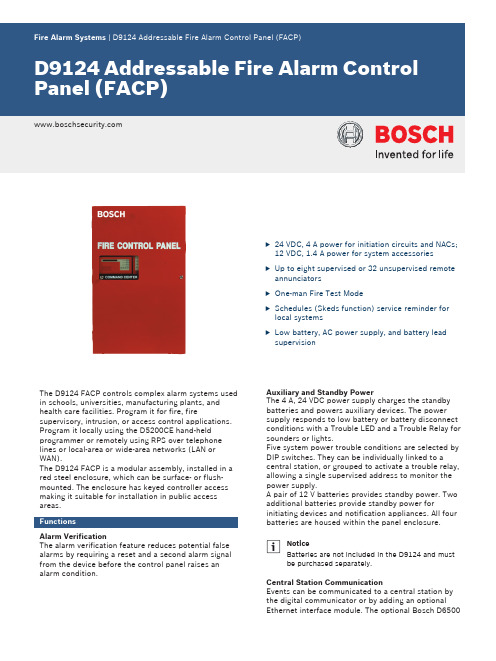
u24 VDC, 4 A power for initiation circuits and NACs;12 VDC, 1.4 A power for system accessories uUp to eight supervised or 32 unsupervised remote annunciatorsu One-man Fire Test ModeuSchedules (Skeds function) service reminder for local systemsuLow battery, AC power supply, and battery lead supervisionThe D9124 FACP controls complex alarm systems used in schools, universities, manufacturing plants, and health care facilities. Program it for fire, firesupervisory, intrusion, or access control applications.Program it locally using the D5200CE hand-held programmer or remotely using RPS over telephone lines or local-area or wide-area networks (LAN or WAN).The D9124 FACP is a modular assembly, installed in a red steel enclosure, which can be surface- or flush-mounted. The enclosure has keyed controller access making it suitable for installation in public access areas.FunctionsAlarm VerificationThe alarm verification feature reduces potential false alarms by requiring a reset and a second alarm signal from the device before the control panel raises an alarm condition.Auxiliary and Standby PowerThe 4 A, 24 VDC power supply charges the standby batteries and powers auxiliary devices. The power supply responds to low battery or battery disconnect conditions with a Trouble LED and a Trouble Relay for sounders or lights.Five system power trouble conditions are selected by DIP switches. They can be individually linked to acentral station, or grouped to activate a trouble relay,allowing a single supervised address to monitor the power supply.A pair of 12 V batteries provides standby power. Two additional batteries provide standby power forinitiating devices and notification appliances. All four batteries are housed within the panel enclosure.NoticeBatteries are not included in the D9124 and must be purchased separately.Central Station CommunicationEvents can be communicated to a central station by the digital communicator or by adding an optional Ethernet interface module. The optional Bosch D6500or D6600 NetCom Receiver and Modem IIIa2 reporting format provide individual point reporting to monitoring facilities.The D5500 Remote Programming Software (RPS) allows the following to be controlled from a central station:•Resetting notification appliances•Activating or deactivating remote annunciation •Activating or deactivating relays•Supervising battery condition•Setting point status and armed status•Enabling or disabling reporting functions •Shunting reporting points during servicingEvent Log Storage, Viewing, and PrintingThe D9124's memory log stores time, date, point, and user ID for up to 1000 events. Programming options allow restricting specific event reports to the central station receiver. A programming option allows the log to record certain functions entered at command centers.Display the 1000 events in memory at the fire system controller(s) or retrieve them with a single phone call by a central station using Bosch RPS version 3.7.025 or higher.The D9131A Parallel Printer Interface Module allows an on-site parallel printer to print events as they are stored in the log: recording time, date, account number, event, point ID, point text, and if the message was transmitted to a receiver.InputsThe D9124 Control Panel is a 127-point addressable system that is expandable to 246 addressable points. The control panel receives information from alarm initiating points through integrated devices over a two-wire multiplex zone expansion system. Each addressable point accommodates both normally-open and normally-closed devices with end-of-line (EOL) resistor supervision. Each point is programmable for fire, fire supervisory, intrusion, or access control applications.OutputsSystem notification appliance capacity can be extended beyond the two supervised circuits by adding D8129 Octo-relay Modules. Up to 128 relay outputs can be operated through the controller or the central station, or they can be programmed for automatic operations.Notification appliances can be programmed for steady, pulsed, California March Time, or Temporal Code 3 patterns. Temporal Code 3 patterns can be synchronized using the appropriate synchronization modules.Notification Appliance Circuits (NACs)The D9124 FACP has two supervised, on-board NACs with individual circuit er InterfaceA D1256 Fire Alarm keypad is visible and accessible behind a locked, clear sliding panel located on the enclosure door. It displays programmable text identifying specific initiating and supervisory devices. It also provides point annunciation, signal silence, trouble silence, detector reset, and annunciator reset. The sliding panel lock is keyed to match the Bosch manual pull stations for resetting the system.Also available as options are:•D1255R Security/Fire Keypad•D1257 Remote Fire Alarm Annunciator•D1260 KeypadInstallation/configuration notesCompatible ProductsThe following products are compatible with the D9124 FACP:Category Product ID Product DescriptionBatteries andPower SupplyProductsBATB-40Battery boxBATB-80Battery boxD12612 V, 7 Ah standby batteryD121812 V, 18 Ah standby batteryD7038Power supply address circuit module Detectors D285Photoelectric smoke headD285TH Photoelectric smoke head with heatD298M Zonex smoke master baseD298S Zonex smoke single baseFMM-462Manual stationD603Rate-of-rise heat detector headD604Fixed (135°F) heat detector headD605Fixed (190°F) heat detector head Keypads andAnnunciatorsD720B/R Security and fire keypadsD1255B/R Security and fire keypadsD1256Fire command centerD1257Remote fire alarm annunciatorD1260ATM keypadModules D125B Powered loop interface module(Dual, Class B)D129Initiation circuit module(Dual, Class A)D130Relay moduleD136Plug-in relayD192C Bell supervision moduleD192E Bell supervision moduleD192G Bell supervision moduleD8125POPEX moduleD8125MUXZonex to dual multiplex interfaceD8128D OctoPOPIT moduleD8129Octo-relay moduleD8130Release moduleD9127U POPIT module (no tamper)D9127T POPIT module (tamper)D9131A Parallel printer interface moduleDX4020Ethernet interface module ProgrammingProductsD5200CE Handheld programmerRPS Remote Programming SoftwareRPS-LITE Remote Programming SoftwareRPS-INTL Remote Programming SoftwareThe D9124 Addressable Control Panel is shipped in three boxes. One box contains:ponent1D9412GLTB Control Panel (less terminal blocks) Another box contains:ponent1D9101 Enclosure Assembly with DoorThe third box contains a D9100 Accessory Module Carrier that includes the following:ponent2D192C Indicating Circuit Supervision Modules1D928 Dual Phone Line Switcher1D8125 POPEX Module (additional optional)1D9142LC 24 VDC Power SupplyThe third box also contains:ponent1D1256 Fire Alarm Keypad1D1601 Transformer1Wiring Harness1Wiring Harness for the D8125 POPEX Module 2560 Ω Resistors (for D192C Modules)2D161 Dual Modular Telephone Cords1D162 Dual Modular Telephone Cord1Literature packEnvironmental ConsiderationsInputsMechanical PropertiesDimensions (H x W x D)OutputsPower RequirementsCurrent (operating)D9124 Addressable Fire Alarm Control Panel (FACP)Up to eight supervised or 32 unsupervised remoteannunciators.Not Available.Order number D9124AccessoriesD101F Lock and Key SetShort‑body lock set with two keys supplied. Uses theD102F (#203) replacement key.Order number D101FD102F Replacement KeyReplacement key (#203) for the D101F lock set.Order number D102FD113 Battery Lead Supervision ModuleSupervises wiring connections for two 12 V batteriesconnected to the same set of charging terminals.Order number D113D122 Dual Battery HarnessHarness with circuit breaker. Connects two batteriesto a compatible control panel.Order number D122D127 Reversing Relay ModuleReports two separate alarm conditions to the centralstation.Order number D127D135A Low‑battery Disconnect ModuleDisconnects the control panel from the battery whenthe battery level drops to 9.5 VDC.Order number D135AD136 Plug‑In RelayMaximum rating is 1 A at 24 VDC or 2 A at 12 VDC.Available individually (D136) or in a package of 25(D136‑25).Order number D136D138 Mounting Bracket, Right AngleUsed to mount accessory modules in D8103, D8108A,and D8109 enclosures.Order number D138Represented by:Americas:Europe, Middle East, Africa:Asia-Pacific:China:America Latina:Bosch Security Systems, Inc. 130 Perinton Parkway Fairport, New York, 14450, USA Phone: +1 800 289 0096 Fax: +1 585 223 9180***********************.com Bosch Security Systems B.V.P.O. Box 800025617 BA Eindhoven, The NetherlandsPhone: + 31 40 2577 284Fax: +31 40 2577 330******************************Robert Bosch (SEA) Pte Ltd, SecuritySystems11 Bishan Street 21Singapore 573943Phone: +65 6571 2808Fax: +65 6571 2699*****************************Bosch (Shanghai) Security Systems Ltd.201 Building, No. 333 Fuquan RoadNorth IBPChangning District, Shanghai200335 ChinaPhone +86 21 22181111Fax: +86 21 22182398Robert Bosch Ltda Security Systems DivisionVia Anhanguera, Km 98CEP 13065-900Campinas, Sao Paulo, BrazilPhone: +55 19 2103 2860Fax: +55 19 2103 2862*****************************© Bosch Security Systems 2014 | Data subject to change without notice 2693048075 | en, V2, 17. Oct 2014。
进口晶振料号、尺寸大全.xls
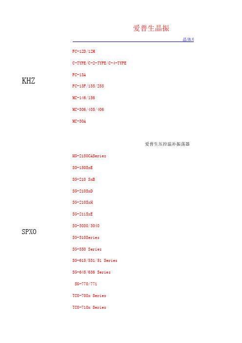
KHZSPXOTCO-710x SeriesSG-770/771TCO-708x Series SG-615/531/51 Series SG-645/636 Series SG-310Series SG-550 Series SG-211SxE SG-3030/3040SG-210SxD SG-210SxH SG-150SxE SG-210 SxB MC-306/405/406 MC-30A爱普生压控温补振荡器HG-2150CASeries FC-13A FC-13F/135/255MC-146/156爱普生晶振晶体单元FC-12D/12MC-TYPE/C-2-TYPE/C-4-TYPE串行RX-8581SA/JE/NB RX-8731LC RX-8803SA/LCRX-5412SF RX-8025SA/NB RX-8571SA/NB/LC RX-4575LC RX-4581NB RX-4803SA/LC RX-4571LC/NB/SA RX-4574LC RTC-8564JE/NB/RX-8564LC RX-4045SA/NBRTC-4543SA/SB RTC-4574SA/JE/NB RTC-4701JE/NBRA-4574SA RA-8565SA RA-8581SA 爱普生实时钟模块32.768KHZRA-4565SA音叉型水晶振动子KHKDS表面封装型振水晶振动子MHZUM-5HC-49/UAT-49UM-4AT-38UM-1SMD-49DMX-38DSX840GA DSX840GT DSX151GAL DSX531SDSX630G DSX321SH DSX530GA DSX321G DSX321SL DSX211AL DSX221SHDSX211A DSX221S DSX211G DSX221G KDS晶振DSX1612ADSR221STHKDS振荡器DSA211SCL (VC-TCXO)DSB211SCL (TCXO)DSB211SCB (TCXO)DSA211SDA (VC-TCXO)DSB211SDA (TCXO)DSB211SDB (TCXO)DSA211SDT (VC-TCXO)DSB211SDT (TCXO)DSA222MAA (VC-TCXO)DSA222MAB (VC-TCXO)DSB222MAA (TCXO)DSB222MAB (TCXO)DSA221SCL (VC-TCXO)DSB221SCL (TCXO)DSB221SCB (TCXO)DSA221SDA (VC-TCXO)DSB221SDB (TCXO)DSB221SDA (TCXO)DSA221SDT (VC-TCXO)DSB221SDT (TCXO)DSA221SJ (VC-TCXO)DSB221SJ (TCXO)DSA321SCL (VC-TCXO)DSB321SCL (TCXO)DSV221SR (1.8V動作タイプ)(VCXO)DSV221SV (2.8V/3.3V 動作タイプ) (VCXO)DSV321SR (1.8V動作タイプ) (VCXO)DSV321SV (2.8V/3.3V 動作タイプ) (VCXO)DSV323SD (HCSL出力) (VCXO)DSV323SJ (LVDS出力) (VCXO)DSV323SK (LV-PECL出力) (VCXO)DSV753HJ (LVDS出力) (VCXO)DSV753HK (LV-PECL出力) (VCXO)DSV753SJ (LVDS出力)(VCXO)DSS753SVC(SSXO)CITIZEN晶振西铁城KHZ晶振CFS-206CMR200TCFS-145CMJ206TCFV-206CM250C西铁城MHZ晶振CSA-310CSA-309HCM49CM309SCS325SCSX-750F CSX-750P CSX-750VNX2012SANX3215SAKHZ谐振器音叉晶振RV-2123-C2精工晶振日本NDK晶振振荡器RV-3029-C2-A RV-3029-C2-BRV-3049-C2-A RV-3049-C2-A RV-3049-C2-B 西铁城晶振振荡器瑞士微晶RV-4162-C7RV-8564-C2NX3215SA NX1612AA NX1612AANX2016SA NX2520SA NX3225GANX5032GA NX5032SA NX1255GB NR-2BNR-2C AT-41CD2京瓷晶振KHZ音叉型号频率尺寸ST2012SB 32.768K 2.0 x 1.2 x 0.6ST3215SB 32.768K3.2 x 1.5 x 0.8石英晶体振荡器KC2520B 32.768K 2.5 x 2.0 x 0.7KC2520M 32.768K 2.5 x 2.0 x 0.7温度-40-125°KC3215A32.768K3.2 x 1.5 x 1.0温度补偿水晶振荡器KT3225T 32.768K3.2 x 2.5 x 1.0TCXOCMOS输出类KC2520B-C11.5~1252.5 x 2.0 x 0.7KHZ谐振器M晶体谐振器SPXO钟用晶体振荡器VCXO晶振KC2520B-C2125~160 2.5 x 2.0 x 0.7KC3225A-C21.5~125 3.2 x2.5 x 0.89(K25-2C)KC5032A-CM 1.789~50 5.0 x 3.2 x 1.2KC5032C-C31.8 ~ 170 5.0 x 3.2 x 1.0(K30-3C)KC5032E-C314.31818~166 5.0 x 3.2 x 1.1KC7050A-C21.8~1257.0 x 5.0 x 1.6(K53-2C)石英晶体振荡器(VCXO)KV5032C-C3 1.5~80 5.0 x 3.2 x 1.0KV7050B-C3 1.5~1707.0 x 5.0 x 1.6石英晶体振荡器(TCXO)KT252013~52 2.5 x 2.0 x 0.8max GPS用KT322513~52 3.2 x 2.5 x 1.0max GPS用 台湾晶技(TXC)32.768KHz贴片频率尺寸9HT732.768K 6.9 x 1.4 x 1.30mm9HT932.768K 4.1 x 1.5 x 0.80mm9HT1032.768K 3.2 x 1.5 x 0.75mm9HT1132.768K 2.0 x 1.2 x 0.60mmMHZ9B 3.2 ~ 90MHz11.5 x 5.0 x 3.68mm49/S9C 3.2 ~ 90MHz12.7 x 4.8 x 3.80mm49/SMD 7A8 ~ 80MHz 5.0 x 3.2 x 1.20mm黑色面7B8 ~ 100MHz 5.0 x 3.2 x 0.90mm7M10 ~ 54MHz 3.2 x 2.5 x 0.70mmAV9.9 ~ 54MHz 3.2 x 2.5 x 0.80mm黑色面8Z12 ~ 54MHz 2.5 x 2.0 x 0.55mm石英振荡器7W 1 ~ 170MHz7 x 5 x 1.3mm7C 1 ~ 150MHz 5 x 3.2 x 1.2mm7X 1 ~ 125MHz 3.2 x 2.5 x 1mm8W 4 ~ 54MHz 2.5 x 2 x 0.8mmVCXO 压控振荡器BK60 ~ 700MHz7 x 5 x 1.3mmCJ60 ~ 200MHz 5 x 3.2 x 1.2mmTCXO 温补振荡器7Q13 ~ 52MHz 3.2 x 2.5 x 1mm7L13 ~ 52MHz 2.5 x 2 x 0.8mmNDK(日本电波工业株式会社)晶体谐振器频率尺寸NX2520SG19.2-54MHZ 2.5*2.0*0.9NX3215SA32.768KHZ 3.2*1.5*0.8NX2520SA16-80MHZ 2.5*2.0*0.5NX3225SA12-150MHZ 3.2*2.5*0.55NX3225GA9.840-50MHZ 3.2*2.5*0.75NX5032GB12-55MHZ 5.0*3.2*1.0NX5032GA8-55MHZ 5.0*3.2*1.3NX5032SD9.75-40MHZ 4.9*3.1*0.9AT-41 3.1375-74.1MHZ11.05*4.7*3.6849/S AT-41CD2 3.1375-74.1MHZ11.4*4.8*4.049/SMD晶体振荡器(SPXO)NZ2520SB 1.5 to 80 2.5×2.0×0.9 NZ2520SB 32.768KHZ 2.5×2.0×0.9 2725N 2.5 to 70 5.0×3.2×1.0 2725T 2.5 to 125 5.0×3.2×1.0 7311S-GF-505P62.5-313MHZ7.0*5.0*1.7温补振荡器(TCXO)NT2520SB13.-52MHZ 2.5*2.0*0.9NT3225SA10-40MHZ 3.2*2.5*1.0NT7050BC19.2-26MHZ7.0*5.0*2.0压控振荡器(VCXO)NV2520SA 1.25-80MHZ 2.5*2.0*0.9 NV3225SA 1.25-80MHZ 3.2*2.5*0.9 NV5032SA38.4-52MHZ 5.0*3.2*1.2 NV7050SA 2.048-700MHZ7.0*5.0*1.6晶体滤波器21E15AB21.4MHZ7.0*5.0*1.35 台湾鸿星(HOSONIC)晶体谐振器频率尺寸2SB12~54MHz 2.5*2.0*0.55mm 3SB12~54MHz 3.2*2.5*0.65mm 5SB10~80MHz 5.0*3.2*0.80mm 6SB8~80MHz 6.0*3.5*1.0mm 7SB6~100MHz7.0*5.0*1.1mm 3FB12~54MHz 3.2*2.5*0.80mm5FA10~80MHz 5.0*3.2*1.20mm黑色面两个脚8FA6~80MHz8.0*4.5*1.60mmHC-49SA 3.2~66MHz11.05*4.65*3.50mmHC-49SB8~66MHz11.05*4.65*2.5mmHC-49SMB8~66MHz12.9*4.7*3.2mmHC-49SMA 3.2~66MHz12.9*4.7*4.2mmDT-2630~100KHzDT-3830~100KHz石英振荡器HXO-31~133MHz7.0*5.0*1.5mmHXO-51~133MHz 5.0*3.2*1.3mmHXO-S1~54MHz 3.2*2.5*1.2mmHXO-N1~54MHz 2.5*2.0*0.9mm台湾希华晶振(SIWARD)晶体谐振器频率尺寸LP-2.5 3.5 ~ 80 MHz11.05 x 4.65 x H49/SLP-3.5 3.5 ~ 80 MHz11.05 x 4.65 x HLP-3.5S 3.5 ~ 80 MHz12.3 x 4.7 x H49/SMDLP-4.2S 3.5 ~ 80 MHz12.3 x 4.7 x HSX-252012 ~ 66 MHz 2.5 x 2.0 x 0.55SX-322510 ~ 125 MHz 3.2 x 2.5 x 0.8SX-50328 ~ 100 MHz 5.0 x 3.2 x 0.7SX-60358 ~ 50 MHz 6.0 x 3.5 x 1.0SX-7050 6 ~ 100 MHz7.0 x 5.0 x 1.1GX-3225410 ~ 54 MHz 3.2 x 2.5 x 0.8黑色面四脚GX-503228 ~ 60 MHz 5.0 x 3.2 x 1.1黑色面两脚和四脚GX-50324GX-603528 ~ 60 MHz 6.0 x 3.5 x 1.1黑色面两脚和四脚GX-60354GX-705026 ~ 70 MHz7.0 x 5.0 x 1.4黑色面两脚和四脚GX-70504石英振荡器SHO-3225 2.5 ~ 60 MHz 3.2 x 2.5 x 0.9OSC73 2.5 ~ 60 MHz 5.0 x 3.2 x 1.05OSC57A40 ~ 160 MHz7.0 x 5.0 x 1.5SPO-2520B 1 ~ 200 MHz 2.5x2.0x0.8SPO-3225B 1 ~ 200 MHz 3.2x2.5x0.9SPO-5032B 1 ~ 200 MHz 5.0x3.2x0.9SPO-7050B 1 ~ 200 MHz7.0x5.0x1.4温补振荡器(TCXO)TXO928 ~ 45 MHz 3.2 x 2.5 x 0.9TXO83 6 ~ 45 MHz 5.0 x 3.2 x 1.05STO-2520B0.675 ~ 55 MHz 2.5 x 2.0 x 0.9STO-3225B0.675 ~ 55 MHz 3.2 x 2.5 x 1.0STO-5032B0.675 ~ 55 MHz 5.0 x 3.2 x 1.05STO-7050B0.675 ~ 55 MHz7.0 x 5.0 x 1.4STO-2520A16.368 ~ 38.4 MHz 2.5x2.0x0.8STO-3225A16.368 ~ 27.456 MHz 3.2x2.5x1.0压控温补振荡器(VC-TCXO)VTX7110 ~ 26 MHz7.0 x5.0 x 1.6VTX928 ~ 45 MHz 3.2 x 2.5 x 0.9VTX83 6 ~ 45 MHz 5.0 x 3.2 x 1.05压控振荡器(VCXO)SCV-3225 1.5 ~ 54 MHz 3.2 x 2.5 x 0.9VCX95 1.5 ~ 61.440 MHz 5.0 x 3.2 x 1.1VCX91 1.5 ~ 54 MHz7.0 x 5.0 x 1.6台湾嘉碩(TST)型号频率尺寸TZ0507A32.768K 4.1x1.5x0.25TZ0601A32.768K7.0x1.5x1.4TZ0756A32.768K 6.5x2.0TZ0824A32.768K 4.1x1.5x0.7TZ0853A32.768K8.0x3.8x2.5TZ1006A32.768K 3.2x1.5TZ1021A32.768K 5.2x1.5TZ1692A32.768K 4.9x1.8x1.0TZ2426A32.768K 6.0x2.0TZ2430A 3.997 HC49UTZ0694A4HC49-SMD 以下嘉碩型号 每一个频率都有不同的型号.太多了,只写了几个TZ0195A6M7.0x5.0x1.1TZ0777A8M 5.0x3.2x1.0TZ0994A8M 6.0x3.5x1.1TZ0419A11.0592 MHZ 4.0x2.5x0.8TZ0481A12MHZ 3.2x2.5x0.7石英振荡器TW0357A32.768KHZ 3.2x2.5x1.2TW0190A6MHZ 3.2x2.5x1.2TW0280A10MHZ 5.0x3.2x1.3TW0229A12.288MHZ7.0x5.0x1.9TW0160A13MHZ 5.0x3.2x1.3TW0135A13.5 5.0x3.2x1.2TW0149A14.318184 5.0x3.2x1.3TW0277A16MHZ 3.2x2.5x1.2TW0286A16MHZ7.0x5.0x1.9压控温补振荡器(VC-TCXO)TX0329A10MHZ 3.2x2.5x1.2TX0173A12MHZ 5.0x3.2x1.2台湾加高晶振(HELE)型号频率尺寸HSX221SR 2.55x2.05x0.95HSX221SA 2.50x2.00x0.50HSX321S 3.20x2.50x0.65HSX421S 4.00x2.50x0.65HSX531S 5.00x3.20x0.75HSX321G 3.20x2.50x0.75HSX530G 5.00x3.20x1.402个脚HSX630G 6.00x3.50x1.202个脚HSX840G8.00x4.50x1.402个脚SMD-4912.10x4.75x4.5049/SMDAT-4911.50x5.00x3.5049/S台湾泰艺(TAITIEN)晶体谐振器 型号频率尺寸XY16~54MHz 2.5 x 2.0XX12~54MHz 3.2 x 2.5XV11~80MHz 5.0 x 3.2X212~48MHz 3.2 x 2.5黑色面XS10~50MHz 5.0 x 3.22脚黑色面XR8~49MHz 6.0 x 3.5XQ7.3728~70MHz8.0 x 4.5XI 3.5~80MHz10.8 x 4.549/SXJ 3.5~80MHz12.5 x 4.5XD32.768KHz 3.2 x 1.5石英振荡器OT HCSL90~125MHz7.0 x 5.0OW80~320MHz 5.0 x 3.2OY1~50MHz 2.5 x 2.0OX32.768KHz ~ 125MHz 3.2 x 2.5PX1~200MHz 3.2 x 2.5OV13.7KHz ~ 125MHz 5.0 x 3.2OC13.7KHz ~ 166MHz7.0 x 5.0OC-M1~200MHz7.0 x 5.0压控振荡器(VCXO)VW CMOS 1.5~80MHz 5.0 x 3.2VT CMOS 1.5~200MHz7.0 x 5.0VT-M CMOS60~200MHz7.0 x 5.0温补振荡器(TCXO)TY13~52MHz 2.5 x 2.0TX13~52MHz 3.2 x 2.5TV10~40MHz 5.0 x 3.2TW 5.0 x 3.210~40MHzTS / TC7.0 x 5.05~40MHzSMI振荡器型号频率尺寸压电晶体谐振器22SMX16.000 MHz to 80.000 MHz2.5*2.032SMX(A)12.000 MHz to 67.500 MHz3.2*2.532SMX(B)16.000 MHz to 50.000 MHz3.2*2.5黑色面42SMX12.000 MHz to 50.000 MHz4.0*2.553SMX(B)10.000 MHz to 270.000 MHz5.0*3.253SMX(C)8.000 MHz to 55.000 MHz5.0*3.2黑色两脚53SMX(D)10.000 MHz to 50.000 MHz5.0*3.2黑色四脚53SMX(E)10.000 MHz to 50.000 MHz5.0*3.2金属面两脚97SMX(A)9.000 MHz to 150.000 MHz6.0*3.5金属面2脚97SMX(B)8.000 MHz to 50.000 MHz6.0*3.5黑色面4脚97SMX(C)8.000 MHz to 50.000 MHz6.0*3.5黑色面2脚94SMX(C) 6.000 MHz to 160.000 MHz5.0*7.0黑色面4脚压电晶体振荡器32SMOP 1.000 MHz to 125.000 MHz3.2*2.599SMOP 1.000 MHz to 181.000 MHz5.0*3.291SMOP 1.000 MHz to 200.000 MHz5.0*7.0黑色面4脚97SMO(K) 1.000 MHz to 166.000 MHz5.0*7.032SMOHG500.000 kHz to 45.000 MHz3.2*2.557SMO40.000 MHz to 300.000 MHz5.0*7.0327SMO(B)32.768 kHz 4.0*2.5压控振荡器(VCXO)32SMOV(M) 2.000 MHz to 54.000 MHz3.2*2.532SMOV(S) 2.000 MHz to 54.000 MHz3.2*2.599SMOV 2.000 MHz to 54.000 MHz5.0*3.297SMOVH 2.000 MHz to 80.000 MHz5.0*7.097SMOV 2.000 MHz to 54.000 MHz5.0*7.0温补振荡器(TCXO)SXO-3200V10.000 MHz to 40.000 MHz3.2*2.5SXO-5200V 5.000 MHz to 45.000 MHz5.0*3.2SXO-7100AV(B)10.000 MHz to 26.000 MHz5.0*7.0大河晶振石英晶体谐振器 型号频率尺寸FCX-06 2.0x1.6x0.5mmFCX-05 2.5x2.0x0.6mmFCX-04C 3.2x2.5x0.7mmFCX-04 3.2x2.5x0.9mmFCX-03 5.0x3.2x1.5mmHC-49/U03C11.4x4.8x4.5mm49/SMD HC-49/U0310.3x5.0x3.6mm石英振荡器FCXO-05 2.5x2.0x0.9mmFCXO-03L 5.0x3.2x1.2mm FCXO-75HC7.0x5.0x2.0mmCTS(西迪斯电子)Model 44312 - 48 3.2 x 2.5 x 0.90 mmModel 44510 - 50 5.0 x 3.2 x 1.35mm TF32 Series32.7680 kHz 3.2 x 1.5 x 0.80 mm 16 - 542.5 x 2.0 x 0.65 mm12 - 50 3.2 x 2.5 x 0.80 mmModel 40512 - 50 5.0 x 3.2 x 0.9 mm Model 40610 - 50 6 x 3.5 x 1.20 mm Model 4078 - 507.0 x 5.0 x 1.20 mm ATS-SM Series 3.2 - 6412.30 x 4.83 x 4.30 mm49/SMDATSSM4P Series 3.2 - 6413.00 x 4.85 x 5.20mmATS Series 3.2 - 6410.85 x 4.50 x 3.68 mm时钟振荡器Model 632 1.0 - 75 3.2 x 2.5 x 1.2 mm Model 636 1.0 - 1255.0 x 3.2 x 1.3 mmCB3CB3LV1.5 - 1607.0 x 5.0 x 1.8 mmCB1V81.0 - 707.0 x 5.0 x 1.8 mmModel 425Model 403MHZ可编程低抖动声表面波VCXO/VCSOTCXOTG-5035CJTG-5035CE XG-1000CA/CB TG-5035CG XG-2121/2102CATG-5021CGEG-2121/2102CB TG-5031CJ EG-41xxCA Series TG-3530SA EG-2101CA TG-5021CEEG-2121/2102CA VG-4512CAEG-2002CA EG-2021/2001CAVG-4231/4232CA VG-4501/4502CA EA-2102CB VG-4231CBSG-8003 Series VG-4231CESG-WriterMA-306 MA-406/505/506器EV-9100JG SG-8002 Series FA-118TFA-20HFA-238V/238/TSX-3225 体单元/谐振器CA-301 FA-128RTC-72421/72423RTC-7301SF/DG应用手册RX-8564LCRX-8581SA/JE/NBRTC-62421/62423RX-4575LCRX-4581NBRX-8025SA/NBRX-4571SA TSU SeriesRX-4574LC XP-7000 Series RX-4574SG晶体压力传感器XV-8000CB/LK RX-4571LC XV-8100CB RX-4571NB 爱普生传感器XV-3500CB RTC-9701JE XV-3700CB RX-4045SA/NB FF-555RTC-4574SA/JE/N RTC-4701JE/NB AH-6120LR/AP-6110LR RTC-8564JE/NB 爱普生滤波器sheet RTC-7301SF/DG RA-8565SA RA-8581SA FF-32N RTC-4543SA/SB 并行RTC-72421/72423 RA-4574SA水晶MHZ 水晶振动子KHZ DSO531SRDSX221G DSO751SR DSR221STHDSO321SWDSX211G DSO321SRDSR221STH DSO221SWUM-5J DSA321SF (VC-TCXO)UM-5DSO213AWDSF753SAF DSO221SRDSF753SCF DT-381HC-49/T DSF444SAF DSO211ARDSF444SAO DT-261DSF753SDF DT-38UM-4DMX-38DSF444SCO DT-26DSF753SBF DMX-26SDSF334SAO DMX-26DSF334SCF SM-14JUM-1SM-26FHC-49/TS DST520DSF753SAO DST621DSF753SCO DST310SDSF334SAF DST410SDSF444SCF 晶振DST210ADSF223SAFDSB321SF (TCXO)DSX321GDSB321SCB (TCXO)DSO321SN (SPXO)DSA321SDA (VC-TCXO)DSO321SR (SPXO)DSB321SDA (TCXO)DSO321SW (SPXO)DSB321SDB (TCXO)DSO323SD (HCSL出力)(SPXO)DSA535SC (VC-TCXO)DSO323SJ (LVDS出力)(SPXO)DSB535SC (TCXO)DSO323SK (LV-PECL出力)(SPXO)DSA535SD (VC-TCXO)DSO531SBM (SPXO)DSB535SD (TCXO)DSO531SBN (SPXO)DSA535SG (VC-TCXO)DSO531SVN (SPXO)DSB535SG (TCXO)DSO531SR (SPXO)DSG211STA (TSXO)DSO533SJ (LVDS出力) (SPXO)DSG221STA (TSXO)DSO533SK (LV-PECL出力) (SPXODSO211AR (SPXO)DSO751SBM (SPXO)DSO211AH (SPXO)DSO751SVN (SPXO)DSO213AW (SPXO)DSO751SBN (SPXO)DSO221SBM (SPXO)DSO751SR (SPXO)DSO221SH (SPXO)DSO753HJ (LVDS出力) (SPXO)DSO221SN (SPXO)DSO753HK (LV-PECL出力) (SPXODSO221SR (SPXO)DSO753HV (SPXO)DSO221SW (SPXO)DSO753SD (HCSL出力) (SPXO)DSO321SBM (SPXO)DSO753SJ (LVDS出力) (SPXO)DSO321SBN (SPXO)DSO753SK (LV-PECL出力) (SPXOCM200C CM315 CM519CM212 CM415HC-49 / U-SCS325DSV753SK (LV-PECL出力)(VCXO) DSV753SV (VCXO)DSS753SVD (SSXO)DSV753HV (VCXO)DSV753SB (VCXO)DSV753SD (HCSL出力)(VCXO) DSV531SV (VCXO)DSV532SB (VCXO)DSV532SV (VCXO)DSO321SH (SPXO)DSV211AV (2.8V/3.3V 動作タイDSV323SV (VCXO)DSV531SB (VCXO)DSO321SVN (SPXO)DSV211AR (1.8V動作タイプ)(VC微晶10KHZ-2100KHZCC7V-T1ACC4V-T1ASSP-T7-FL VT-150-FVT-200-FL VT-120-FSSP-T7-F VTC-120-FVT-200-F SSP-T2A-FNZ2016SA7311S-GF-505P NH21M13LANZ2016SF 7311S-DF-505P9325DSPXO振荡器NZ2520SB7311S-DF-104P NH25M22WC NZ2520SD7311S-GF-255R NH20M20LA NZ2520SFNH25M22WB NZ2520SGNT2016SA 2725NNT2520SA 10T7.5BH 2735NNT3225SA 21E15AA 2725T5925A-AQP50 90E9A 2765E5936L-GJD70 YF10.0BP NV11M09YANW36M25LA AF10-24DS NV7050SANW34M25WA 70NE15B 7311QNW19M12WA 45SC15BENV13M09WJ NW19M12WB 度-40-125°OCXO晶振晶体滤波器SPXO振荡器TCXO振荡器FCXO晶振和四脚色面两脚和四脚色面两脚和四脚FS-585NS-21RNS-32R/FS-335/555晶振滤波器/SB/JE/NB /NB/NB NBNBJE/NB 62423 72423 /DGO)O) SPXO)XO) (SPXO)XO) (SPXO)XO) XO) (SPXO)プ)(VCXO)作タイプ)(VCXO)O)VCXO)WXB55Z1486FE WF871Q0429CD声表滤波WF995D0355CDWFB40D1732CE。
EPCS4中文资料(Altera)中文数据手册「EasyDatasheet - 矽搜」

Yes
No
Yes
EPCS64
67,108,864
NoBiblioteka YesNoYes
EPCS128 134,217,728
No
Yes
No
Yes
须知 表 3-1: (1)要设置这些设备采用Altera编程单元或主编程器,请参考 (2)EPCS装置可以被重新编程系统与字节冲击波II下载线缆或使用SRunner外部微处理器.欲了解更多
CC 该EPCS准备.如果它
是不是,你必须持有 n配置 低到EPCS所有电源轨都准备好.
FPGA控制
nSTATUS and CONF_DONE 在AS配置过程中销
模式.如果 CONF_DONE 信号不高配置或者结束
信号变高太早,FPGA将脉冲其
nSTATUS 引脚为低电平启动
重新配置.在成功配置中,FPGA释放
DATA0, DCLK, ASDO,and nCSO 在FPGA控制信号,
分别.
图3-2
示出串行配置设备经由一个编程
下载线,其配置在AS模式中FPGA.
图3-3
显示一个串口
使用APU或第三方编程器配置在AS配置模式下FPGA配置器件编程.
f
有关串行配置器件引脚说明详细信息,请参阅
表3-23.
图 3-2.
操作
电压( V)
3.3 3.3 3.3 3.3 3.3
对于8引脚SOIC封装,可以从EPCS1垂直迁移到EPCS4 或EPCS16因为相同器件封装中EPCS器件提供. 同样,对于一个16引脚SOIC封装,您可以垂直从EPCS16到EPCS64或EPCS128迁移.
使用压缩比计算来确定FPGA器件以适合EPCS.
- 1、下载文档前请自行甄别文档内容的完整性,平台不提供额外的编辑、内容补充、找答案等附加服务。
- 2、"仅部分预览"的文档,不可在线预览部分如存在完整性等问题,可反馈申请退款(可完整预览的文档不适用该条件!)。
- 3、如文档侵犯您的权益,请联系客服反馈,我们会尽快为您处理(人工客服工作时间:9:00-18:30)。
7;5A<6?@>?FEL<G B8I:?@D>G<B8M:EDI8:I ;8I8:E@B/IG=:5>07;6KF>27KF>26KF>28/Chmmhf ob^p0Onmebg^Ebf^glbhglEJIB@D<;@C<DH@EDH+L@G@D>;@8>G8C 8D;F:9E8G;B8MEJIUgbm?ffPDC LZrhnm 70Ghk ab`a bgknla ehZ]pbma ma^lm^Z]r2lmZm^\nkk^gm h_e^ll maZg 95B1ie^Zl^\ahhl^mri^J380Ug]^k ma^Zf[b^g\^pbma ]Zg`^khnl `Zl ebd^I 7S1SO 7hk NO 71pZla mb`am mri^bl k^\hff^g]^]@ie^Zl^m^lm ma^k^eZr bg k^Ze Ziieb\Zmbhgl3J_ma^Zf[b^g\^Zeehpl1]nlm ikhm^\m^]bl ik^_^k^gmbZeer k^\hff^g]^]390K F>bl Zg ^gobkhgf^gmZe _kb^g]er ikh]n\m3Pe^Zl^fZkdZ li^\bZe \h]^/:::0hk /::60pa^g hk]^kbg`3/::60lmZg]l RhIS \hfiebZgm pbma DZ]fbnf \hgmZ\m@/:::0lmZg]l _hk RhIS \hfiebZgm pbma DZ]fbnf2_k^^\hgmZ\m3DZ^Q]7W^e]bg`ib\mnk^l _hk KF>pbma mpblmbg`\hii^k pbk^3Pe^Zl^lahp p^e]bg`lmre^/B mh J 0Zg]ma^e^g`ma h_pbk^l pa^g hk]^kbg`3Pe^Zl^fZkdma^e^g`ma h_^Z\a pbk^_khf e^_m mh kb`am b_ma^e^g`ma bl ]b__^k^gm3/Chmmhf ob^p0H<I~OZY^NO^OWZ]Q*G<H<I~OZY^NO^Z[QY*SFTRFSFT SFTRFSFT Mhngmbg`T^kfbgZe Mhngmbg`T^kfbgZeMhngmbg`T^kfbgZe/\hgmZ\m \ehl^0/\hgmZ\m hi^g0/\hgmZ\m \ehl^0/\hgmZ\m hi^g0SFTRFSFT Mhngmbg`T^kfbgZe/\hgmZ\m \ehl^0/\hgmZ\m hi^g0SFTRFSFT Mhngmbg`T^kfbgZe/\hgmZ\m \ehl^0/\hgmZ\m hi^g0Mhngmbg`T^kfbgZe Mhngmbg`T^kfbgZeMhngmbg`T^kfbgZeH<I~OZY^NO^OWZ]Q*H<I~OZY^NO^OWZ]Q*H<I~OZY^NO^OWZ]Q*H<I~OZY^NO^Z[QY*H<I~OZY^NO^Z[QY*H<I~OZY^NO^Z[QY*KF>26KF>27KF>28KF>261R6KF>271R7KF>281R8KF>281R:KF>281R97;7Wbkbg`EbZ`kZf EJIB@D<;@C<DH@EDH+L@G@D>;@8>G8C 8D;F:9E8G;B8MEJIUgbm?ffPhlbmbo^iheZkbmrN^`Zmbo^iheZkbmrN^`Zmbo^iheZkbmr7;8=04/aA61RA;5501=05/aA71RA8550=06/aA61RA<5501=1-/aA71RA8:50=./aA61RA:5501=//aA71RA7:50=0/aA61RA:5501=1/aA71RA7:50=6/aA61RA8<501=.-/aA71RA6=:0=../aA61RA<5501=.//aA71RA8:50=.4/aA61RA;;501=.5/aA71RA8850=.6/aA61RA8;501=/-/aA71RA6=50=/2/aA61RA8=501=/3/aA71RA6>50=/4/aA61RA:5501=/5/aA71RA7:50=00/aA61RA95501=01/aA71RA7550=02/aA61RA;5501=03/aA71RA8550Smre^h_fZg`Zgbg langmDZ^Q]7Smre^G6mh G991ma^mab\dg^ll h_langm?aA6hk aA71R?k^lblmZg\^h_langm [^mp^^g B2C i v 1f 65,j=2=.0/aA61RA8>501=.1/aA71RA6>:0=/./aA61RA9:501=///aA71RA77:0=/6/aA61RA:5501=0-/aA71RA7:50=4/aA61RA8;501=5/aA71RA6=50=.2/aA61RA8:501=.3/aA71RA6<:0=/0/aA61RA:5501=/1/aA71RA7:50=0./aA61RA=5501=0//aA71RA9550EJIB@D<;@C<DH@EDH+L@G@D>;@8>G8C 8D;F:9E8G;B8MEJIUgbm?ffEbl\eZbf^kTabl ]ZmZla^^m bl _hk ma^\nlmhf^klx k^_^k^g\^3Bee ma^li^\b_b\Zmbhgl Zk^ln[c^\m mh \aZg`^pbmahnm ghmb\^3W^\hne]ghm ^oZenZm^Zee ma^i^k_hkfZg\^Zg]Zee ma^iZkZf^m^kl _hk ^o^kr ihllb[e^Ziieb\Zmbhg3Tanl ma^nl^k lahne][^bg Z kb`am ihlbmbhg mh \ahhl^ma^lnbmZ[e^ikh]n\m _hk ma^bk hpg Ziieb\Zmbhg3J_ma^k^bl Zgr jn^kr1ie^Zl^\hgmZ\m Ihg`_Z _hk ma^m^\agb\Ze l^kob\^3Ihp^o^k1bm bl ma^nl^kxl k^lihglb[bebmr mh ]^m^kfbg^pab\a ikh]n\m lahne][^nl^]hger3t XbZf^g Ihg`_Z Fe^\mkhZ\hnlmb\Dh31Lm]3Bee kb`aml h_Ihg`_Z Zk^k^l^ko^]37;9DZ^UOQ63R^eZr bl hg ma^yl^mz lmZmnl pa^g [^bg`k^e^Zl^]_khf lmh\d1pbma ma^\hglb]^kZmbhg h_lah\d kbl^g _khf mkZglbm Zg]k^eZr fhngmbg`1k^eZr phne][^\aZg`^]mh yk^l^mz lmZmnl1ma^k^_hk^1pa^g Ziieb\Zmbhg /\hgg^\mbg`ma^ihp^k lniier01ie^Zl^k^l^m ma^k^eZr mh yl^mz hk yk^l^mz lmZmnl hg k^jn^lm373Jg hk]^k mh fZbgmZbg yl^mz hk yk^l^mz lmZmnl1^g^k`bs^]ohemZ`^mh \hbe lahne]k^Z\a ma^kZm^]ohemZ`^1bfinel^pb]ma lahne][^:mbf^l fhk^maZg yl^mz hk yk^l^mz mbf^3Eh ghm ^g^k`bs^ohemZ`^mh yl^mz \hbe Zg]yk^l^mz \hbe lbfnemZg^hnler3Bg]Zelh ehg`^g^k`bs^]mbf^/fhk^maZg 6fbg0lahne][^Zohb]^]383Ta^m^kfbgZel h_k^eZr pbmahnm mpblm^]\hii^k pbk^\Zg ghm [^mbg2lhe]^k^]1\Zg ghm [^fho^]pbee_neer1fhk^ho^k mph m^kfbgZel \Zg ghm [^_bq^]Zm ma^lZf^mbf^3Smre^5:;k BAw937Smre^5:;26k BAw:37Smre^5<;k BAw937Smre^5<;26k BAw:37Smre^5<<k BAw937Smre^5<<26k BAw:37Smre^5<<27k BAw;37Dhgg^mhk lmre^Trib\Ze langm \hgg^\mbhg pZrlDZ^Q]7W^\Zg fZd^li^\bZe \hgg^\mbhg Z\\hk]bg`mh \nlmhkf^k.l k^jnbk^f^gm3Pe^Zl^ikhob]^nl pbmama^]kZpbg`1Zg]langm li^\b_b\Zmbhg Zg]\hgg^\mhk.l li^\b_b\Zmbbhg3GQXN\V760Jg \Zl^h_gh mhe^kZg\^lahpg bg hnmebg^]bf^glbhg?hnmebg^]bf^glbhg g 6ff1mhe^kZg\^lahne][^u537ff@hnmebg^]bf^glbhg l 6ffZg]g :ff1mhe^kZg\^lahne][^u538ff@hnmebg^]bf^glbhg l :ff1mhe^kZg\^lahne][^u539ff370Ta^mhe^kZg\^pbmahnm bg]b\Zmbg`_hk PDC eZrhnm bl ZepZrl u536ff3EJIB@D<;@C<DH@EDH+L@G@D>;@8>G8C 8D;F:9E8G;B8MEJIUgbm?ffSmre^h_fZg`Zgbg langmDZ^Q]7Smre^G6mh G991ma^mab\dg^ll h_langm?aA6hk aA71R?k^lblmZg\^h_langm [^mp^^g B2C i v 1f 65,j=1./aA61RA99501=1//aA71RA7750=10/aA61RA;5501=11/aA71RA8550。
