SMD系列操作手册
伦茨 SMD系列变频器 说明书

17
c[mm]
83 92
m[kg]
0.5 0.6
93
85
146
128
17
141
1.2
114
105
146
128
17
140
1.4
114
105
146
128
17
171
1.9
114
105
146
100
17
171
1.7
型号
a[mm] a1[mm] b[mm] b1[mm] b2[mm] c[mm]
371L4TXA
[kW] 0.37 0.75 1.1 1.5 2.2 3.0 4.0 5.5 7.5 11 15
ESMD371L4TXA 0.37 ESMD751L4TXA 0.75 ESMD112L4TXA 1.1 ESMD152L4TXA 1.5 ESMD222L4TXA 2.2 ESMD302L4TXA 3.0 ESMD402L4TXA 4.0 ESMD552L4TXA 5.5 ESMD752L4TXA 7.5 ESMD113L4TXA 11 ESMD153L4TXA 15 ESMD183L4TXA 18.5 ESMD223L4TXA 22
52 45 46 40 42 37 69 60 64 55
①额定电压下 , 斩波频率为 4,6,8kHz 时 ②额定电压下 , 斩波频率为 10kHz 时 ③最大输出电流随 C90 的设定(选择输入电压)而改变
5
安装
4 安装
4.1 机械安装 4.1.1 1AC 控制器外形尺寸
> 50
b2 b1 b
电压,频率
1/N/PE 230/240V 2/PE 230/240V (180V-0%...264V+0%)
SMD、SMG、SFG 搅拌器和推流器 50 Hz 安装和使用说明书

SMD, SMG, SFGMixers and flowmakers50 Hz安装和使用说明书GRUNDFOS说明书中文 (CN)2中文 (CN) 安装和使用说明书中文版本这些安装和操作说明介绍了格兰富SMD、SMG、SFG 搅拌器和推流器。
章节1-6介绍了以安全的方式拆包、安装并启动本产品所需的信息。
章节7-11介绍了有关产品的重要信息,以及有关服务、故障查找和产品处置的信息。
目录页1. 一般信息本手册包含关于格兰富SMD、SMG搅拌器和SFG推流器的安装、操作和维护的说明。
这些产品设计用于低粘度到中等粘度 (≤ 500 mPas) 液体中的各种搅拌应用,例如搅拌均匀和保持悬浮。
1.1 本文献中所用符号2. 安全指导2.1 安全概述1.一般信息21.1本文献中所用符号22.安全指导22.1安全概述23.接收产品33.1运输产品33.2检查产品33.3储存产品34.安装产品34.1扭矩34.2搅拌器和推流器定位44.3安装一台搅拌器54.4安装一台推流器85.电气连接135.1电机保护135.2齿轮箱/机封室保护145.3过载继电器145.4启动方式155.5SMG和SFG的接线图155.6接线图165.7转动方向195.8电化学腐蚀的防护196.启动该产品197.产品介绍197.1产品描述197.2应用207.3标识218.维护228.1污染的搅拌器或推流器228.2服务一览表238.3机油248.4换油249.故障查找2510.技术数据2710.1一般技术数据2710.2电机2710.3齿轮箱,仅SMG、SFG 2710.4机封2710.5桨叶2710.6声压级2711.回收处理27警告装机前,先仔细阅读本安装操作手册。
安装和运行必须遵守当地规章制度并符合公认的良好操作习惯。
注意AMD.07.18.1410搅拌器有单独的安装与操作指导。
参见 网页, 出版号 96526302 。
关于Ex版本AMD、AMG和AFG的信息,请参见上编号为96498078的文件。
LENZE_SMD操作手册

17
92
0.6
ESMD751X2SFA
ESMD152X2SFA
114
105
146
128
17
124
1.2
ESMD222X2SFA
114
105
146
128
17
140
1.4
6
4.1.2 3AC 控制器外形尺寸
安装
> 50
b2 b1 b
4×M4 2.4 Nm 21 Ib-in
> 15
> 15
> 50
a1
a
1.1 关于此操作手册
·本操作手册包含 smd变频器的重要技术数据,描述了该变频器的安装、操作及调试方法。 ·本手册仅适用于软件版本为 rev 14 的控制器。 ·调试前请先阅读本操作手册。
1.2 名词解释
名词 控制器 传动系统
在本手册中的含义 smd 系列变频器 包含 smd 系列变频器及其它 Lenze 传统产品的传动系统
1
安全信息
2 安全信息
1. 一般信息 控制器运行时,某些部件可能会带电、旋转或发热,不正确地开盖,不当使用,安装或运行 错误均可能导致人员伤害或设备损坏。 本设备的运输、安装、调试及维护必须由训练有素的合格人员完成(参见 IEC364、 CENELEC HD384 或 DIN/VDE0100 及 IEC 664 号报告…)。 合格人员指具有一定资格并熟悉本产品的安装、调试、操作的人员。
2
安全信息
5. 运行: 必要时,装有本控制器的系统应装有符合安全规范的监控和保护装置,例如可用系统适配的软 件对其进行监控。 掉电后,不要立即触摸控制器的运动部件和电源接头,因为此时一些已充电的电容正在放电。 6. 符合 UL 标准的控制器 UL 信息适用于符合 UL 标准的系统,其中包含有关 UL 标准的详细信息。
SMD分光机使用

主题SMD分光机作业指导书页次1/7第一步:(机器检查和启动)1、检查SMD分光机是否正常,并将材料盒清除干净。
2、将分光机的所有数据清零。
同时启动电脑,打开光电测试系统。
第二步:(基本参数设置)设置分光机的基本参数。
(图A-1)1、首先选者“LED类型”(见图A-1)、A.单色光LED:一般指单色,红,黄,绿。
B.白光LED:指一般白光(暖白,正白/冷白)2、选者LED的脚位架构可测试:两脚单晶,两脚双晶,三脚双晶四脚三晶,六脚三晶(常规3825两脚单晶;5050六脚三晶)发核审文件编号:版次: V1主题SMD分光机作业指导书页次2/73、中间脚位:如LED类型为三脚双晶或三脚三晶时,则应设置共阴(负极)或共阳(正极)否则选择“无”;4、排向测试:如果所有LED进行测试时都是一个方向,则测试时不用对每一个LED进行排向测试,只要设定方向即可,如正极在前,则择“正极”,负极在前则选者“负极”;5、光强测量选择:是利用光谱卡加积分球还是探测器进行测量。
(常规选择“探测器”)如选择光谱卡测量亮度〈光强IV〉则可设置测量亮度的哪一种物理量,可选者亮度〈Mcd 〉,能量〈Lm〉两种。
6、临界波长可设定A.临界波长:适用于双晶,设定两个晶片之间的波长分界点或适用与三晶,设定第一个晶片和其它晶片着间的下限波长分界点,以便排向测试。
B.临界波长2:仅适用于三晶片,设定第一个晶片和其它晶片之间的上限波长分界点(临界波长为下限值,临界波长2为上限值),以便选择晶片。
7、VF采样方式:(常规选择“内部”)选定内部:指VF值从电路内部读取(其中VF值会包括接线阻抗压差,但比较稳定)选择外部:指测量VF值时电路采用Kelvin 法,可避免接触电阻和线阻造成之测量误差。
8、XY打靶点数与结果记录数A.可设定对在量测白光时,材料在色坐标图上的打靶点数。
(常规3528为2000 / 5050为1000)B.可设定对在量测材料时,软件对量测数据保存的材料数量。
SMD-30 30-XS伺服驱动器硬体操作说明书

SMD-30/30-XS硬体操作说明书匯出日期:2023-05-10修改日期:2021-04-192023/05/10, 21:101 序言感谢您长期对本公司产品的使用与支持。
本公司伺服团队不断致力於各项产品的研发,期许本公司产品与服务能给使用者带来最大的效益。
新代高性能驱动器系列产品为本公司最新推出之伺服驱动器,本产品使用高品质之元件与材料,并经过严格测试,采用精密向量控制,具有高精确度、高稳定性、高效率之特性。
本使用说明内容包括驱动器的硬体规格、安装、配线与讯号,能提供给使用者最正确的指引与操作,为充分发挥产品应有的优异性能与维护人员及设备的安全,在使用前请详细阅读本使用手册,并且妥善保存,以备日後调校与保养时使用,若有任何疑虑,请与本公司联络,本公司专业人员将竭诚为您服务。
2 适用机型本单轴操作手册适用於新代SMD-30/30-XS 驱动器。
3 硬体规格3.1 说明每部驱动器在出厂前均经过详细品管检查与防撞包装处理,请使用者收到产品後应先检查外观有无撞击损伤,并将外盒与产品上之序号做比对是否一致,若有不符,请第一时间与本公司联络。
型号说明3.2 外观介绍SMD-30/30-XS驱动器功能模塊說明A M3串行通讯端口连接上位控制器与下一站驱动器,串行通讯100MbpsB Mini USB端口连接个人计算机C I/O讯号端口外接电池端口连接I/O设备(急停、警示灯…等)连接绝对型编码器供电用电池D STO讯号端口STO接口,2组安全输入,1组安全功能回授E编码器回授由上至下分别为第一与第二埠。
第一端口与第二端口为连接马达编码器。
F外供电源连接三相交流电200V~230V(RST)G控制电源若有安规需求,可将控制电源自L1,L2独立供电,连接单相交流电200~230V,输入电压规格需与RST相同。
H回生电阻两种接法,择一使用即可:1. 外部回生电阻连结至P、B22. 内建煞车为将B1、B2短路I电机电源供给连接马达侧提供马达电源(UVW)J记忆用电池提供绝对式编码器记忆功能所需之电源3.3 外形尺寸3.4 驱动器规格新代驱动器SMD-30/30-XS电源额定电源电压三相200~230V 50/60Hz电源电压容许-15 ~ +10%范围电源频率变动±5%范围输出额定输出电流7.6A x 2过电流能力150% 60s、200% 1s控制方式三相全波整流,SVPWM-VVVF控制回生电阻内建、可外接外接,请参考回生电阻选用章节回授编码器支援串列介面:Tamagawa、SYNNET、NIKON、FeeDAT选配扩充编码器模组:支援Tamagawa、SYNNET、NIKON、ABZ、串列、SSI、BiSS (不支援UVW省配线型编码器)(若要使用扩充编码器模组,请参考伺服10PX1/10PX3扩充模组操作文件) PC通讯介面MINI-USB控制器串列通Mechatrolink III讯介面输出入信号数位输入4点,可规划数位输出2点,可规划STO双通道安全扭矩停止开关(2I 1O)冷却方式风扇冷却环境温度0℃ ~ 55℃(若环境温度超过45℃以上时,请强制周边空气循环)、储存:-20~65℃ (非冻结)湿度最大90% RH (非结露)、储存:90%RH以下 (非结露)安装地点室内(避免阳光直射);无腐蚀性气体、易燃性气体、油雾或尘埃海拔1000公尺以下至海平面振动最大 5.9 m/s2重量 3.9 kg•••••••••••••••••••••4 搬运与安装4.1 搬运搬运时必须拿取驱动器的机身,不能只拿取上盖或其中部分,否则可能造成掉落的危险。
SMD LED 照明系列操作手册说明书
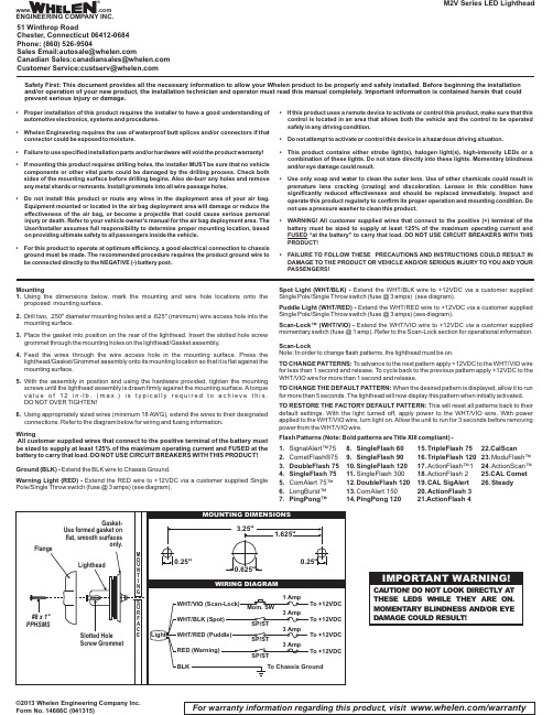
Mountinging the dimensions below,mark the mounting and wire hole locations onto the proposed mounting surface.2.Drill two,.250"diameter mounting holes and a.625"(minimum)wire access hole into the mounting surface.3.Place the gasket into position on the rear of the lighthead.Insert the slotted hole screw grommet through the mounting holes on the lighthead/Gasket assembly.4.Feed the wires through the wire access hole in the mounting surface.Press the lighthead/Gasket/Grommet assembly onto its mounting location so that it is flat against the mounting surface.5.With the assembly in position and using the hardware provided,tighten the mounting screws until the lighthead assembly is drawn firmly against the mounting surface.A torque v a l u e o f 12i n -l b.(m a x.)i s t y p i c a l l y r e q u i r e d t o a c h i e v e t h i s.DO NOT OVER TIGHTEN!ing appropriately sized wires (minimum 18AWG),extend the wires to their designated connections.Refer to the diagram below for wiring and fusing information.WiringAll customer supplied wires that connect to the positive terminal of the battery must be sized to supply at least 125%of the maximum operating current and FUSED at the battery to carry that load.DO NOT USE CIRCUIT BREAKERS WITH THIS PRODUCT!Ground (BLK)-Extend the BLK wire to Chassis Ground.Warning Light (RED)-Extend the RED wire to +12VDC a customer supplied Single via Pole/Single Throw switch (fuse @3amps)(see diagram).©2013 Whelen Engineering Company Inc.Form No. 14666C (041315)M2V Series LED LightheadFor warranty information regarding this product, visit /warrantySpot Light (WHT/BLK)-Extend the WHT/BLK wire to +12VDC a customer supplied via Single Pole/Single Throw switch (fuse @3amps)(see diagram).Puddle Light (WHT/RED)-Extend the WHT/RED wire to +12VDC a customer supplied via Single Pole/Single Throw switch (fuse @3amps)(see diagram).Scan-Lock™(WHT/VIO)-Extend the WHT/VIO wire to +12VDC a customer supplied via momentary switch (fuse @1amp).Refer to the Scan-Lock section for operational information.Scan-LockNote:In order to change flash patterns,the lighthead must be on.TO CHANGE PATTERNS:To advance to the next pattern apply +12VDC to the WHT/VIO wire for less than 1second and release.To cycle back to the previous pattern apply +12VDC to the WHT/VIO wire for more than 1second and release.TO CHANGE THE DEFAULT PATTERN:When the desired pattern is displayed,allow it to run for more than 5seconds.The lighthead will now display this pattern when initially activated.TO RESTORE THE FACTORY DEFAULT PATTERN:This will reset all patterns back to their default settings.With the light turned off,apply power to the WHT/VIO wire.With power applied to the WHT/VIO wire,turn light on.Allow the unit to run for 3seconds before removing power from the WHT/VIO wire.Flash Patterns (Note:Bold patterns are Title XIII compliant)-1.SignalAlert™75etFlash®753.DoubleFlash 754.SingleFlash 75Alert 75™6.LongBurst™7.PingPong™8.SingleFlash 609.SingleFlash 9010.SingleFlash 12011.SingleFlash 30012.DoubleFlash Alert 15014.PingPong 12015.TripleFlash 7516.TripleFlash 12017.ActionFlash™118.ActionFlash 219.CAL SigAlert 20.ActionFlash 321.ActionFlash 422.CalScan23.ModuFlash™24.ActionScan™25.CAL Comet 26.SteadySafety First: This document provides all the necessary information to allow your Whelen product to be properly and safely installed. Before beginning the installation and/or operation of your new product, the installation technician and operator must read this manual completely. Important information is contained herein that could prevent serious injury or damage.•Proper installation of this product requires the installer to have a good understanding of automotive electronics,systems and procedures.•Whelen Engineering requires the use of waterproof butt splices and/or connectors if that connector could be exposed to moisture.•Failure to use specified installation parts and/or hardware will void the product warranty!•If mounting this product requires drilling holes,the installer MUST be sure that no vehicle components or other vital parts could be damaged by the drilling process.Check both sides of the mounting surface before drilling begins.Also de-burr any holes and remove any metal shards or remnants.Install grommets into all wire passage holes.•Do not install this product or route any wires in the deployment area of your air bag.Equipment mounted or located in the air bag deployment area will damage or reduce the effectiveness of the air bag,or become a projectile that could cause serious personal injury or death.Refer to your vehicle owner's manual for the air bag deployment area.The User/Installer assumes full responsibility to determine proper mounting location,based on providing ultimate safety to all passengers inside the vehicle.•For this product to operate at optimum efficiency,a good electrical connection to chassis ground must be made.The recommended procedure requires the product ground wire to be connected directly to the NEGATIVE (-)battery post.•If this product uses a remote device to activate or control this product,make sure that this control is located in an area that allows both the vehicle and the control to be operated safely in any driving condition.•Do not attempt to activate or control this device in a hazardous driving situation.•This product contains either strobe light(s),halogen light(s),high-intensity LEDs or a combination of these lights.Do not stare directly into these lights.Momentary blindness and/or eye damage could result.•Use only soap and water to clean the outer e of other chemicals could result in premature lens cracking (crazing)and discoloration.Lenses in this condition have significantly reduced effectiveness and should be replaced immediately.Inspect and operate this product regularly to confirm its proper operation and mounting condition.Do not use a pressure washer to clean this product.•WARNING!All customer supplied wires that connect to the positive (+)terminal of the battery must be sized to supply at least 125%of the maximum operating current and FUSED “at the battery”to carry that load.DO NOT USE CIRCUIT BREAKERS WITH THIS PRODUCT!•FAILURE TO FOLLOW THESE PRECAUTIONS AND INSTRUCTIONS COULD RESULT IN DAMAGE TO THE PRODUCT OR VEHICLE AND/OR SERIOUS INJURY TO YOU AND YOUR PASSENGERS!®ENGINEERING COMPANY INC.51 Winthrop RoadChester, Connecticut 06412-0684Phone: (860) 526-9504SalesEmail:*******************CanadianSales:************************CustomerService:*******************www..comWarnings to InstallersWhelen’s emergency vehicle warning devices must be properly mounted and wired in order to be effective and safe. Read and follow all of Whelen’s written instructions when installing or using this device. Emergency vehicles are often operated under high speed stressful conditions which must be accounted for when installing all emergency warning devices. Controls should be placed within convenient reach of the operator so that he can operate the system without taking his eyes off the roadway. Emergency warning devices can require high electrical voltages and/or currents. Properly protect and use caution around live electrical connections.Grounding or shorting of electrical connections can cause high current arcing, which can cause personal injury and/or vehicle damage, including fire. Many electronic devices used in emergency vehicles can create or be affected by electromagnetic interference.Therefore, after installation of any electronic device it is necessary to test all electronic equipment simultaneously to insure that they operate free of interference from other components within the vehicle. Never power emergency warning equipment from the same circuit or share the same grounding circuit with radio communication equipment.All devices should be mounted in accordance with the manufacturer’s instructions and securely fastened to vehicle elements of sufficient strength to withstand the forces applied to the device. Driver and/or passenger air bags (SRS) will affect the way equipment should be mounted.This device should be mounted by permanent installation and within the zones specified by the vehicle manufacturer, if any.Any device mounted in the deployment area of an air bag will damage or reduce the effectiveness of the air bag and may damage or dislodge the device. Installer must be sure that this device, its mounting hardware and electrical supply wiring does not interfere with the air bag or the SRS wiring or sensors. Mounting the unit inside the vehicle by a method other than permanent installation is not recommended as unit may become dislodged during swerving; sudden braking or collision. Failure to follow instructions can result in personal injury. Whelen assumes no liability for any loss resulting from the use of this warning device. PROPER INSTALLATION COMBINED WITH OPERATOR TRAINING IN THE PROPER USE OF EMERGENCY WARNING DEVICES IS ESSENTIAL TO INSURE THE SAFETY OF EMERGENCY PERSONNEL AND THE PUBLIC.Warnings to UsersWhelen’s emergency vehicle warning devices are intended to alert other operators and pedestrians to the presence and operation of emergency vehicles and personnel. However, the use of this or any other Whelen emergency warning device does not guarantee that you will have the right-of-way or that other drivers and pedestrians will properly heed an emergency warning signal. Never assume you have the right-of-way. It is your responsibility to proceed safely before entering an intersection, driving against traffic, responding at a high rate of speed, or walking on or around traffic lanes. Emergency vehicle warning devices should be tested on a daily basis to ensure that they operate properly. When in actual use, the operator must ensure that both visual and audible warnings are not blocked by vehicle components (i.e.: open trunks or compartment doors), people, vehicles, or other obstructions. It is the user’s responsibility to understand and obey all laws regarding emergency warning devices.The user should be familiar with all applicable laws and regulations prior to the use of any emergency vehicle warning device. Whelen’s audible warning devices are designed to project sound in a forward direction away from the vehicle occupants. However, because sustained periodic exposure to loud sounds can cause hearing loss, all audible warning devices should be installed and operated in accordance with the standards established by the National Fire Protection Association.。
SMD数字零件计数器操作指引
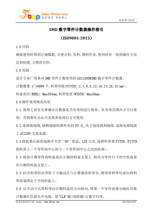
SMD数字零件计数器操作指引(ISO9001-2015)1.0目的确保使用时得到正确数据,方便点料,发料,领料作业.使用时有一致的操作方法.达到快捷,方便的目的。
2.0范围适合于本厂用来对SMD零件计数使用的ASC1000BSMD数字零件计数器。
计数数量:1~49999个,料带间隔(PITCH):2,4,6,8,12,16,24,28,32(mm)。
料盘直经(REEL):Max383mm,料带宽度(WIDTH):Max56mm。
3.0操作使用规范内容3.1使用之前首先要确认计数器是否有效的进行保养,在有效范围内才可以使用,否则要作出认可及保养处理后方可使用。
3.2连接接地线,插梢端接机器外壳的FG孔,夹子端连接到地线;连接电源线接上AC220V交流电源。
3.3将机器后面的电源开关至''ON''状态,LCD点亮,选择所需要PITCH.(PITCH 指料带上一个零件的中心到下一个零件的中心之间的距离)。
3.4将欲计数零件的料盘装在左侧的料盘支架上.将符合零件尺寸的空料盘装在右侧的料盘支架上。
3.5拉出料带经由导轮下方输送孔与计数器齿轮密合,继续将料带往前拉将料带前端固定于空的料盘上。
3.6以手动方式将料带向右侧料盘的方向移动,将第一个零件前缘分隔柱对准计数器红色箭头中央线,按"CLR"键(清除键)让数字归零。
4.0自动计数模式:4.1按下"MANL/AUTO"键设定成"AUTO"状态.(LCD上SET格位下方为空白状态)。
4.2按下"START"键(启动键)即可计数。
5.0手动计数模式:5.1按下"MANL/AUTO"键设定成"MANL"状态.(LCD上SET格位下方为"00000"状态).此时请设定欲计数之数量。
5.2按下"START"键(启动键)即可计数,机器会在超过所需要计数数量些许停止(因马达煞惯性所造成)。
SMT SMD元件计数器操作说明书

SMT/SMD Components Counter Functions &OperatingInstructionProduct Introduction:-Matters Need AttentionFunction Keys And Operation Procedures InstructionsHow To Connect The Printer Operation(selective use)Simple Trouble ShootingProduct IntroductionPrinciple of the product:-The SMD counter adopts the principle of photoelectric sensing,and uses the corresponding relation between the guide hole and the part,through the special-purpose processing chip and the large-scale centralized circuit processing,realizes the zero error,accurately measures the number of SMD parts,can realize the convenient and quick count,is the high efficiency auxiliary equipment of SMT material management.Product features:-Completely automatic way computation components quantity,facilitates a material,sends the material work simplicity of operator,has a special inventive mind against material belt will fall off the design to reduce to the material belt’s injury to the smallest,forward and reverse all may count,but preinstall quantity,will calculate quantity precisely,zero error.May install the scanning gun and the bar code printer,facilitates the management work.Product specifications:-Power supply: AC220V,/A100V 50/60 HZ, 25WCounting range: -99999- 99999PCSOutlook size: L470*W300*H180mmWeight:10 kgProduct applicationThe SMD material belt type components are all suitableDiameter of belt wheel:Any size is all suitablePITCH: 1,2,4,8,10,12,16,24,32,44,56 mmWIDTH: 4,6,8,12,16,24,32,44,56mm (note: smaller or wider distance can be developed or customized according to demand)Product construction:-Two kind of models1-Ordinary components counter2-Leak hunting components counter1.Charging mirror2.Tray3.Gear/movable blanks4.Wrench5.Rocket head6.Movable arm7.Display8.Power switch9.keys10.Handle11.Fiber optic amplifier12.Optical fiber buttMatters need attention1.After unpacking, please check if all the attachments are complete.2.Please read the operation manual carefully before using and keep it properly.3.Check whether the voltage specification is consistent with that ofmunicipal power.4Please make sure to connect the ground wire to ensure the safety of the person and parts.Function Keys And Operation Procedures Instructions1、功能说明1)PRINT”Operation method: press this button, the number of parts and quantities can be counted by the barcode printer.2)“SET”If "00000" is displayed at the lower left corner of the display screen, you can directly press the number key to enter the number of parts to be calculated: press the "SET" key again to change to manual mode, and "****" is displayed at the lower left corner of the display screen. Manual and automatic modes are switched through this key. (note: the automatic mode is the preset value before the disk material, and the machine will stop automatically when it rotates to the set value. In the manual mode, the machine will stop only when the "stop/reset" key is pressed manually or all materials are finished.)Operation method: after pressing this button, the PITCH value of the display screen will flash, then input the spacing of materials, and then press the "ENTER" button to confirm. If no button is pressed for 5 seconds, the memory will be automatically memorized, and the sound of a drip will be returned to standby state.4)“正传Positive direction/RIGHT”Operation method: press this button to start counting parts in the positive direction, that is, the number shows a positive number or increases. When printing, press this button to move the cursor to the right to set the parameters.5)“The opposite direction/LEFT”Operation method: press this button to start counting parts in the opposite direction, that is, the number displays negative number or decreases. When printing, press this button to move the cursor to the left to set the parameters.6)“STOP/RESET”Operation method:-1.In the state of counting or returning, press this button to stop counting or returning.2.In standby mode, press this button for more than two seconds to clear the COUNT value.3.Press this button when printing the interface to return to the main interface.4.Press this button to stop and return to the standby screen during self-test.Operation method: in standby mode, press this button for 1 second, and the machine conducts self-check test; In automatic mode, press this key to clear the set number; Set the toggle button for the print interface parameters when printing.8)“ LOSS”Operation method: press this button to turn on or off the function of Leak hunting9)“ TIME”Operation method: this button is the switching key of motor speed. Press this button, and the LCD screen will switch between H(high speed), M (medium speed) and L(low speed).10)“ENTER”Operation method: when setting parameters in the print interface, press this button to save the parameters set.2、操作流程Operation process1) connect the power cord to the host and connect the AC220V power supply2) turn on the POWER switch of the machine panel, and the LCD panel will shine3) press PITCH to set the spacing of parts to be counted and press "ENTER". Place the parts to count on the left side tray.4) manually pull out the material belt and clamp it between the material plate and counting gear, and align the intermediate hole of the first part and blank space to the middle line of the material plate.5) press the "stop/reset" button for 2 seconds to return the number to zero. Note: when pulling the material belt, the counting gear will rotate and count.6) press the "setting" button to switch to manual and automatic mode. If you choose automatic mode, you must input the quantity you want to count. Otherwise, press "forward" and the motor will not rotate.7) pull the material belt by hand and wind it to the empty material plate. Press "forward /RIGHT" to count.8) the motor will stop when the quantity arrives. Due to the inertia principle, the number of counts may be more or less than the set value of about 1, which can be manually rotated to the LCD display set value in the direction of the material disk, that is, the number of parts.9) after counting, press "reverse /LEFT" tape and then roll it back to the original LEFT panel, and then stop rotating.三、贴片计数器了解打印机操作说明(选用)How To Connect The Printer Operation(selective use)1、Inspecting device1) make sure the parts counter and BAR code host are connected2) make sure the bar code printer paper is installed correctly.2、Debugging device1) start the part counter power switch2) start the power switch of the host of BAR CODE: power indicator light and ready indicator light are on. At this time, press the FEED key of the host of BAR CODE (automatic alignment button) to make the printing paper automatic alignment. (P.S: if the POWER light is flashing, which means the machine is broken, please restart the POWER switch or FEED key and execute3、PrintPress "PRINT" on the main interface to display the PRINT interface, and the first line of the word interface shows: company name (self-setting); The second line shows the print operation.1) after entering the print interface, there will be a blinking cursor on the third line. At the cursor point again, the content can be edited and modified.2) in the print interface, press LEFT/ reverse to move the cursor to the LEFT, and press RIGHT/ forward to move the cursor to the RIGHT.3) enter Numbers and letters directly at the cursor. If you press a button in the 0--9 key continuously for a short time, you can switch between Numbers and letters on the key. Where the 1 key is used to switch special symbols, letter case and so on.4) after editing the lines, the cursor stays at the line. Press ENTER to display OK on the left side of the line and save the contents of the line. (note: save the editing lines must be the cursor in the line location and then press the ENTER key to deposit, for example: if you want to save the first and second lines, must be the cursor at the first line by pressing the ENTER key, can keep the contents of the first line, the cursor in the second row content save xiali, not at the same time save)5) SELECT to enter the interface of printing parameters on the print interface, where XYWH:XXX, XXX, XXX are displayed respectively to set the position X, Y, width and height of the printed barcode.6) press the stop/reset button to return to the main page7) press PRINT again to PRINT the contents of the PRINT interfaceAdditional attached: the scanner will display on the printing interface after scanning the bar code, press the print button to print.四、简易故障排除 Simple trouble shooting故障状况Fault conditions排除方法Elimination methods打开电源后LCD 无任何显示,无蜂鸣器响声After power on the LCD without any display, no buzzer sound电源线脱落或保险丝松动,请检查 Please check the power cord or loose fuse打开电源后LCD 无任何显示,有蜂鸣器响声The LCD has no display when the power is turned on LCD 屏线松动或损坏,请检查或联系销售商更换 LCD screen line is loose or damaged, please check or contact the seller for replacementLCD 正常显示,但按正/反转启动无效LCD display is normal, butpositive/reverse startup is invalid1. 计数数量大于或等于设定数量或盘料前选用自动模式未设定数,请参阅说明说操作须知2. 电机信号线或电源线接触不良1. The number of counts is greater than or equal to the set number or the number is not set in the automatic mode before feeding. Please refer to the instructions for operation2. Bad contact between motor signal line or power line。
SMD数字零件计数器操作指引

SMD数字零件计数器操作指引(ISO9001-2015)1.0目的确保使用时得到正确数据,方便点料,发料,领料作业.使用时有一致的操作方法.达到快捷,方便的目的。
2.0范围适合于本厂用来对SMD零件计数使用的ASC1000BSMD数字零件计数器。
计数数量:1~49999个,料带间隔(PITCH):2,4,6,8,12,16,24,28,32(mm)。
料盘直经(REEL):Max383mm,料带宽度(WIDTH):Max56mm。
3.0操作使用规范内容3.1使用之前首先要确认计数器是否有效的进行保养,在有效范围内才可以使用,否则要作出认可及保养处理后方可使用。
3.2连接接地线,插梢端接机器外壳的FG孔,夹子端连接到地线;连接电源线接上AC220V交流电源。
3.3将机器后面的电源开关至''ON''状态,LCD点亮,选择所需要PITCH.(PITCH 指料带上一个零件的中心到下一个零件的中心之间的距离)。
3.4将欲计数零件的料盘装在左侧的料盘支架上.将符合零件尺寸的空料盘装在右侧的料盘支架上。
3.5拉出料带经由导轮下方输送孔与计数器齿轮密合,继续将料带往前拉将料带前端固定于空的料盘上。
3.6以手动方式将料带向右侧料盘的方向移动,将第一个零件前缘分隔柱对准计数器红色箭头中央线,按"CLR"键(清除键)让数字归零。
4.0自动计数模式:4.1按下"MANL/AUTO"键设定成"AUTO"状态.(LCD上SET格位下方为空白状态)。
4.2按下"START"键(启动键)即可计数。
5.0手动计数模式:5.1按下"MANL/AUTO"键设定成"MANL"状态.(LCD上SET格位下方为"00000"状态).此时请设定欲计数之数量。
5.2按下"START"键(启动键)即可计数,机器会在超过所需要计数数量些许停止(因马达煞惯性所造成)。
SMD系列-步进电机快速入门指南说明书

Digital DRIVE for Brushless motorsSMD SeriesStepper mode Quick Start guideSMD-Stepper Quick Start Guide-1935-EN Read manual before installing and followall instructions with this icon:Stepper Quick Start GuideTable of contentsAUXILIARY CONFIGURATION (1)GEAR BOX CONFIGURATION (2)STAND ALONE MODE (3)ENABLE THE DRIVE (4)Start Incremental encoder configuration window:•Encoder type: Pulse/Direction•Number of point per turn: indicate the number of pulses given for a turn.For example, if a PLC send 4000 pulses for one turn, Number of points per turn = 4000.•Related feedback, and offset are not used for stepper mode.•Reverse of meaning: tick if you want reverse the sense.Start the GearBox configuration window:•Slave distance / Master distance: Allow to configure the ratio between the master (Auxiliary encoder) and the slave (Servo drive motor), this indicate which distance will be done by the slave for a determined distance of the master.•Acceleration: indicate the master distance before apply the full configured ratio. During the Acceleration distance, the ratio grow up from 0 to the configured ratio•Revertable indicate that the gearbox work in both direction.Stand alone modeNow we must configure the drive to automatically after the startup, start the gearbox mode. The Master axis and slave axis will be automatically linked together on the startup. Chose the gearbox mode here:Enable the driveThe drive must be enabled. There are two ways:ing Drive Studio software:a.Pass Onlineb.Enable the Drive on the right vertical bar2. Using the Input Enable:The input 1 must be configured with the “Special function” Enable.Set value to “Validation”. Then now, if the input E1 goes to logical level ‘1’, the drive goes to Enable and the motor is now linked to the auxiliary pulses.。
SMD定位操作指导书
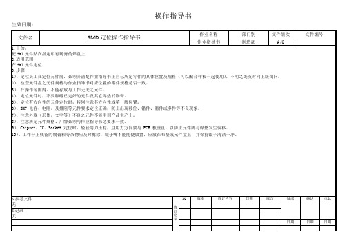
SMD定位操作指导书
作业名称
部门别
文件版次
文件编号
作业指导书
制造部
A/0
1.目的:
把SMT元件贴在指定印有锡膏的焊盘上.
2.适用范围:
在SMT元件定位。
3.步骤
1)、定位员工在定位元件前,必须弄清楚作业指导书上自己所定零件的具体位置及规格(可以配合样板一起使用),不明之处及时向上级询问。
2)、检查元件盘之元件规格与作业指导书对应位置的零件规格是否一致。
3)、在操作范围内,不能存放与工作无关之元件。
4)、定位元件时,不要触碰已定好的元件及其它焊垫的锡膏。
5)、定位有方向性的元件定位时,特别注意其方向性或第一脚位置。
6)、SMT 电容、电阻、及排阻等元件要求定位正确,防止出现移位、错件、漏件或多件等不良现象。
7)、注意外观(形体、文字等)不良之元件不能用到产品生产上。
修订记录
NO
版本
修订内容
日期
修改
做成
确认
承认
无
6.记录
无
日期
日期
日期
操作指导书
生效日期:
8)、注意所定元件规格、厂牌必须与作业指导书之要求一致。
9)、Chipset、IC、Socket 定位时,轻轻用力压稳,且用力方向要与 PCB 板垂直,以防止元件脚与焊垫发生偏移。
10)、工作台上残留的锡膏粒等
5.参考文件
SMD使用说明及产品应用3

深圳市寶安區沙井鎮新橋第二工業區5排7棟 電話:86-755-29878168
網址: 傳真:86-755-27299177
QS9000/ISO14001認証企業,ERP企業資源計劃管理!
使用說明-靜電
<1.本產品是對靜電敏感的產品.在使用上需要十分注意.特別是在超過絕對最大額定 的電流和電壓時會損害或破壞產品.在使用產品時請做好完全的靜電和電涌對策. <2.檢查通電流的電路﹐例如電流開關時發生的電涌不要超過絕對最大額定的電流﹐ 對于驅動電路請插入適當的保護電路. <3.作為使用中的靜電和電涌對策,人體接地(戴防靜電手套及靜電環),導電性墊子, 導電性工作服,導電性鞋和導電性容器等是比較有效果的. <4.本產品與低電阻的金屬表面等接觸時由于急劇的放電現象所引發障礙危險性變 高。工作台等與產品接觸的部分請用導電性墊子(表面電阻率例106~~108Ω/sq) 等通過電阻部分接地(例如裝材料的料盒采用防靜電料盒﹐包裝袋采用防靜電袋) <5.烙鐵的尖端請一定要接地.另外,對于容易產生靜電的環境推荐使用離子發生器.
網址: 傳真:86-755-27299177
QS9000/ISO14001認証企業,ERP企業資源計劃管理!
使用說明-吸嘴
<3.吸嘴设置不当产生的异常 选取合适的吸嘴是提高产品品质的关健所在,因 LED 与其 它电子元件不同,它所承担的不只是电性的输出还有光学部份的 输出,因此特性决定了 LED 的命运在 SMT 过程中变的比较脆 弱。若机器吸嘴下压高度設置的不当,即当吸嘴在吸起和放下材 料的时候都有可能造成对 LED部金线的损伤造成 LED 的不亮或 闪烁及品质问题。
深圳市寶安區沙井鎮新橋第二工業區5排7棟 電話:86-755-29878168
SMD零件计数器操作说明书

設備名稱 SMD 零件計數器 設備功能 計數 文件編號 設備型號
廠 商
版 本
一﹑計數說明﹕
1. 將計數器放置於平穩桌面。
2. 將電源線連接主機﹐並接AC220V 電源。
3. 將機臺面板的POWER 電源開關打開﹐此時LCD 面板會發亮。
4. 將面料盤支架關節的定選鈕逆時針轉松﹐將面料盤支架展開成一字﹐再將固定旋鈕順時針轉緊。
5. 按PITCH ﹐選擇要計數的零件之間距﹕(如a.GST5009之產品REEL 帶有4個小孔每個孔之間的中心距為4mm ﹐此數為行業標準﹐那麼零件之間距為4*4=16mm ﹔b.24HST 系列產品REEL 帶有6個小孔﹐每個孔之間中心距為4mm ﹐那麼零件之間距為4*6=24mm ﹔c.GS5014之產品REEL 帶有5個小孔﹐每個孔之間的中心距為4mm ﹐那麼零件距為4*5=20mm)﹐此時PITCH 的數值會閃爍﹐再可按0~9鍵﹐直接輸入PITCH 的尺寸﹐PITCH 鍵為選擇下一參數。
6.選擇到所需之PITCH 後﹐按ENTER 鍵確認。
核 准
審 核 制 作 日 期
料盤支架
料盤支架
光纖
計數齒輪
LCD
按鍵面板。
SMD带装机设备操作说明书
2
1
5
8
9
6
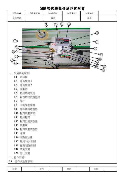
一﹑設備功能說明﹕
1.1送料輪
1.2溫度控制1
1.3溫度控制2
1.4計數器
1.5熱封時間設定
1.6送料帶速度調整鈕
1.7導杆
1.8手動間歇開關
1.ห้องสมุดไป่ตู้零件缺料感應器
1.10壓刀氣壓調節
1.11熱封壓刀
1.12壓刀位置調整鈕
1.13氣壓閥
1.14壓刀氣壓調整器
1.15電源
1.16原點復位鍵
1.17熱封/冷封開關
1.18往復/連續開關
1.19啟動開關
1.20停止開關
二﹑操作步驟﹕
2.1操作前准備事項﹕
2.1.1.輸入電壓220V。
2.1.2.輸入高壓空氣5kg/cm2。
2.1.3.熱封器A﹑B溫度設定一般120-190℃之間(依室溫而定)。
2.1.4.收料輪包裝帶﹐塑封帶輪﹑包裝帶﹑塑帶定位。
2.2安裝送料輪盤上﹑下帶輪盤﹕
2.3.1.松開送帶輪壓力調整鈕。
2.3.2.放入送帶輪。
2.3.3.調整送帶輪調整鈕壓力。
2.3安裝收料輪盤﹕
2.3.1.松開收料輪調整鈕。
2.3.2.放入收料輪。
2.4將包裝帶放置于作業平台的導軌里﹐調整作業移動按鈕﹑壓緊﹑然后將旋鈕退回二格﹐使其能在導軌上自動滑行。
三﹑注意事項﹕
3.1壓刀溫度較高﹐禁止用手觸模。
3.2壓刀﹑溫度﹑速度設定根據拉力計測定值的大小﹐而相應調整。
3.3維護保養。
3.4作業完畢時﹐應該對機表面清潔。
3.5使用一段時間后﹑壓刀加熱至250℃軟化沾膠﹑并用干淨挂布擦式。
3.6每天檢查氣壓計﹐其壓力應在5kg/cm2。
SMD-40点焊机说明书
SMD系列中频电阻焊机使用说明书OPERATION MANUAL FOR MFDC WELDER■型号: SMD-40■控制系统: HJ-PLC-MT6070■出厂编号: HJ-201301045感谢贵公司使用上海豪精之焊接设备。
请你在安装焊机及启用前能详细研读本说明之正确使用方法及注意事项,如有疑问可直接向本公司查询,本公司乐于为阁下解答。
SMD系列中频逆变式点焊机是一套先进的焊接设备,该系列焊机之重要器件包括逆变器、焊接控制器及中频变压器,采用模组化设计,选用进口元器件并配以本公司之先微电脑多功能HJ-MF2控制器,该控制器采用德国先进PLC控制,配合2组模拟/数字转目录一、特点与用途 (3)二、技术数据 (4)三、控制箱操作说明 (6)四、结构概述 (11)五、焊机的安装 (13)六、焊机的维护与保养 (14)七、焊接缺陷的消除 (15)附录1 预压时间调较方法附录2 中频电阻焊机主要元件清单附录3 电路示意图3. 接通焊机电源前,应确定启动开关(脚踏开关或按钮)不在工作(接通)状态;4. 作任何保养检查或检修时,必须关掉或切断焊机电源开关,并由合格技师进行操作(尤其接触带高压电之逆变器、中频焊接变压器等部件);5.不要在有腐蚀性气体或灰尘太多的地方使用焊机,避免控制箱接触水或油;6. 勿放重物于控制箱上;7. 应尽量保持环境清洁,应避免铁屑和过重湿气侵入,定期检查可能松动的地方,如接线端、螺丝等。
特点与用途SMD系列中频逆变式排焊机是一套先进的焊接设备。
应用广泛,焊接变压器体积小而输出能量大。
应用于汽车工业中之一体式变压器速焊钳更见其优越处。
而其优越性能乃因其焊接变压器频率由现时之市电50/60Hz提升至1000Hz,极大地减少了铁芯材料的重量,再加上变压器次级回路中的整流二极管把电能转为直流电源供给焊接使用。
这样可以大大的改善次级回路感应系数值,这是一个引致能量损失的重要因素,在直流焊接回路中几乎是可以不予考虑的,从而将生产成本降至最低。
SMD零件计数器设备操作说明书

SMD零件计数器设备操作说明书
设备操作说明书
第 1 页共2页
设备名称 SMD 零件计数器设备功能计数文件编号设备型号
厂商
源尚
版本
B0
一﹑计数说明﹕
1. 将计数器放置于平稳桌面。
2. 将电源线连接主机﹐并接AC220V 电源。
3. 将机台面板的POWER 电源开关打开﹐此时LCD 面板会发亮。
4. 将面料盘支架关节的定选钮逆时针转松﹐将面料盘支架展开成一字﹐再将固定旋钮顺时针转紧。
5. 按PITCH ﹐选择要计数的零件之间距﹕(如a.GST5009之产品REEL 带有4个小孔每个孔之间的中心距为4mm ﹐此数为行业标准﹐那么零件之间距为4*4=16mm ﹔b.24HST 系列产品REEL 带有6个小孔﹐每个孔之间中心距为4mm ﹐那么零件之间距为4*6=24mm ﹔c.GS5014之产品REEL 带有5个小孔﹐每个孔之间的中心距为4mm ﹐那么零件距为4*5=20mm)﹐此时PITCH 的数值会闪烁﹐再可按0~9键﹐直接输入PITCH 的尺寸﹐PITCH 键为选择下一参数。
6.选择到所需之PITCH 后﹐按ENTER 键确认。
7.将欲计数的零件装在左侧料盘支架上﹐右侧放置一空的相应REEL 带。
8.拉出REEL 带﹐使小孔朝下﹐放入中央部分的计数齿轮上﹐前端需固定于空的REEL 带之上。
9.以手动方式将REEL 带向右侧方向转动﹐将第一个产品第一个孔位与最后一个空装的最后一个孔位之中心部位对准计数器黑色中央线.
核准
审核制作日期料盘支架
料盘支架
光纤
计数齿轮
LCD
按键面板
设备操作说明书第2页共2页。
贴片元件(SMD)手册
SMT资料(铁匠)SMT资料(铁匠)一般PCBA由两部分组成:SMT和PTH第一部分:SMT(Surface Mount Technology表面贴片技术)SMT(Surface Mount Technology)是电子业界一门新兴的工业技术,它的兴起及迅猛发展是电子组装业的一次革命,被誉为电子业的”明日之星”,它使电子组装变得越来越快速和简单,随之而来的是各种电子产品更新换代越来越快,集成度越来越高,价格越来越便宜。
为IT(Information Technology)产业的飞速发展作出了巨大贡献。
第一章、SMT零件SMT所涉及的零件种类繁多,样式各异,有许多已经形成了业界通用的标准,这主要是一些芯片电容电阻等等;有许多仍在经历着不断的变化,尤其是IC类零件,其封装形式的变化层出不穷,令人目不暇接,传统的引脚封装正在经受着新一代封装形式(BGA、FLIP CHIP等等)的冲击,在本章里将分标准零件与IC类零件详细阐述。
一、标准零件标准零件是在SMT发展过程中逐步形成的,主要是针对用量比较大的零件,本节只讲述常见的标准零件。
目前主要有以下几种:电阻(R)、排阻(RA或RN)、电感(L)、陶瓷电容(C)、排容(CP)、钽质电容(C)、二极管(D)、晶体管(Q)【括号内为PCB(印刷电路板)上之零件代码】,在PCB上可根据代码来判定其零件类型,一般说来,零件代码与实际装着的零件是相对应的。
1、零件规格:(1)、零件规格即零件的外形尺寸,SMT发展至今,业界为方便作业,已经形成了一个标准零件系列,各家零件供货商皆是按这一标准制造。
标准零件之尺寸规格有英制与公制两种表示方法,如下表公制表示法 1206 0805 0603 0402英制表示法 3216 2125 1608 1005含义 L:1.2inch(3.2mm)W:0.6inch(1.6mm) L:0.8inch(2.0mm)W:0.5inch (1.25mm) L:0.6inch(1.6mm)W:0.3inch(0.8mm)L:0.4inch(1.0mm)W:0.2inch(0.5mm)注:a、L(Length):长度; W(Width):宽度; inch:英寸b、1inch=25.4mm(2)、在(1)中未提及零件的厚度,在这一点上因零件不同而有所差异,在生产时应以实际量测为准。
- 1、下载文档前请自行甄别文档内容的完整性,平台不提供额外的编辑、内容补充、找答案等附加服务。
- 2、"仅部分预览"的文档,不可在线预览部分如存在完整性等问题,可反馈申请退款(可完整预览的文档不适用该条件!)。
- 3、如文档侵犯您的权益,请联系客服反馈,我们会尽快为您处理(人工客服工作时间:9:00-18:30)。
TUV
CERT
I S 09001
SMD
SMD Range
Installation and Maintenance Instruction
1 2 3 4 5
6
3
1
2
434
55Adjustment of actuator
SMD Adjustment of integral -type modulating SMD range
The adjustment of integral-type actuators have been done
in our factory. Generally, It is not necessary to re-adjust.
If the arm of actuator is not a good position with the valve,
please taking the arm apart from actuator, changing the
The Configuration of positioner (GAMK)The Configuration of logic control board
Configuration is easily accomplished by moving switch and jumpers.
Remote control of an actuator equipped with the electric logic board can be done from an external voltage supply
or internal voltage supply. Inputs on the board are completely isolated by opto-isolators.
Dry contacts control refer Fig5
In case of dry contact control, a jumper must be put on customer terminals 31-32. Voltage control refer Fig6
Caution: never connect voltage higher than 55V on common 5
31-32
6
3155V
Self-holding local control
General stop
The fault-monitoring relay indicates a non-availability of the actuator or an abnormal operation. The fault-monitoring relay is normally energized, and is de-energized in case of fault.
Fault monitoring relay
The relay is de-energized upon the following events:--Loss of main power supply, control voltage, or fuse --Loss of one phase (in case of three phase supply)--Tripping of motor thermal protection
--Loss of input signal 4-20mA (with option positioner)--Local/remote selector in position local or off The optional positioner is connected to the basic electric board. The positioner allows the actaator to reach position proportionally to a command-input signal. The configuration panel of the positioner allows:
POSITIONER OPTION (refer Fig3)
--To give local positioning command
--To adapt the actuator to the different types of input signals --To configure the reaction of the actuator in case of loss of input signal
Move switch 4 and 8 to position B for operation with an input signal of 0-20mA. The output signal(position indication feedback) is also 0-20mA.
Operation with signal 0-20mA.
Operation with signal 0-20mA.
4-20mA
O FF 3
0-20mA 48 B
0-20mA
0-20mA
0-20mA
The standard is 4mA valve closed and 20mA valve open.Operation direction connection (anti-clockwise action)
Move switch 3 to position A, and move actuator potentiometer connection from position `POT STD` to POT REV` to obtain 4mA valve open, 20mA valve closed.This adjustment is factory set, but can be adjusted with the potentiometer `DEAD BAND` . To reduce the dead band, turn it counter-clockwise.
Caution: reducing the dead band too much will provoke `hunting` of the actuator.LOCAL OPERATION
It is possible to simulate an input signal of 4-20mA locally to check the operation of the actuator. The local/remote selector must be in the remote position.
4mA
20mA
3A POT STD
POT REV
4-20mA
red LED goes off.Case 2: actuator starts closing, stops on the close limit switch, and the LED indicating closing is still on.
Turn actuator feedback potentiometer slowly until the LED goes off.
Adjustment of 100%
The local/remote selector must be in remote position. Move local control switch to position 100% for the 2
LED
LED
100%
100
Turn the handwheel to operate the actuator until in the full
close position, by means of a screw-driver press and rotate 4
the cam 4 to the position in which it can trip the limit
switch for close position, lift the screw-driver, the cams
are locked in this position at once. Proceed on the same
way for the open position.
baoheng@
YMD
SMD
MD。
