3BHS125090_A_Power Cables__ Specification
杰尼奥电子有限公司 - 泵类产品说明书
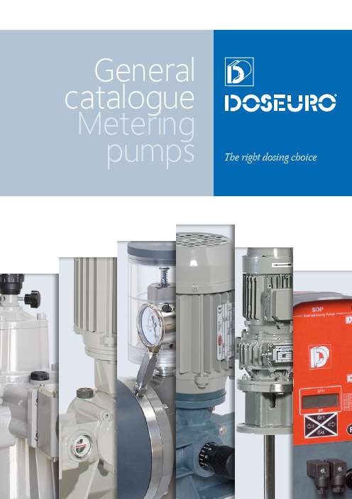
Metering pumpsTHE COMPANYDoseuro is a combination of two capabilities: the first is a solid technical knowledge, obtained during a multi-year experience in the dosing field, while the second is a commercial understanding of the changes in this field and sensitivity to our customers’ requirements. These two factors aresupported by a strong company structure that meets our customers’ demands.The continuous research and principal effort directed to the customer satisfaction are the fundamental reasons of Doseuro success, whichEach of our products speaks for itself. Highreliability is achieved by constant productdevelopment, updating production techniques,everlasting quality control and rigorous testing at allstages of production.WATER ANDEFFLUENT TREATMENTPHARMACEUTICALSAND TEXTILESHORTICULTURALAPPLICATIONS CHEMICALS ANDDYESTUFFS TANNINGPAPER INDUSTRY FOOD PRODUCTION*T h e W o r l d O v e rMAIN FEATURESAll Doseuro pumps are fitted as standard with top quality 4 pole electric motors that conform to the UNEL-MEC specifications, and range from 0.09-4.0 kW at European standard 3 phase voltages of 230/400V @ 50Hz. Non standard motors are available to many alternative specifications, including different voltages and frequencies, insulation standards, and special explosion-proof versions.The dosing rate is fully adjustable via a manually controlled eccentric cam mechanism with spring return, or positive return according to API standard 675.Automatic adjustment is available by means of servo-control motors, pneumatic control or motor frequency control, interface PROFIBUS or other BUS, if required. The reduction system, made of an endless screw coupled to a worm-wheel, makes thegearbox very strong.Our pumps are complemented by a wide range of accessories which include, foot valve/strainers, pressure relief and loading valves, injection fittings and pulsation dampeners.Special versions of construction are available to suit our clients specific applications.A VIEW OVER THE PRODUCTION RANGE Doseuro chemical dosing pumps are available in three main versions. Plunger pumps with packed plungers, plunger/hydraulic diaphragms or mechanical diaphragms. High pressure pumps are available too, upon request. The range also includes various driving methods, such as electric motor or electromagnetic solenoid operation. The company also manufactures complete dosing packages, electric mixers, and fully automatic plants for the dissolution and mixing of polyelectrolyte, both aspowder and emulsion.The most common fields of application for Doseuro chemical dosing pumps are listed in the pictures below.RUBBER AND PLASTICSOIL AND GASIRON, STEEL, COAL AND CONSTRUCTIONNAVAL AND CIVILIAN MARINEAND WHEREVER THERE IS A FLUIDMANY ENGINEERING PROJECTS* available for selected productsPositive Displacement Plunger Dosing PumpAI series plunger dosing pumps comply with mechanical and performance API 675 standards. Furthermore they comply with ATEX standard, therefore they can be installed in Hazardous area. Mechanism is an internal worm gear, fully oil bath lubricated with possibility to be coupled with others independently from the size and stroke number to obtain multi-heads unit.Stroke adjustment can be carried with the pump at rest or in operation and it can be manual or automatic through automatic actuator driven by 4-20 mA; different BUS; pneumatic. Accuracy within ± 1% within 10-100% of rated capacity.As plunger pumps they are reliable and easy for maintenance and with the possibility to have flushing or leakage recovery system (optional).Wide choice of wetted materials: S.S.316L; PVC; PP; PVDF; PTFE other materials available upon request.Fittings– Relief valves and back pressure valves– Safety relief valve– Injection valve– Foot valve– Pulsation dampeners– Calibration pot ModelMax Capacityin Lt/hMax pressurein Barg A I 17538550 A I 250126540 A I 350356940 AP A I 17544230 AP A I 250160230 AP A I 350477250 Note: higher pressure are availablePositive Displacement Sandwich Hydraulic Diaphragm Dosing pumpSDI Sandwich Hydraulic diaphragm dosing pumps comply with mechanical and performance API 675 standards.Furthermore they comply with ATEX standard, therefore they can be installed in Hazardous area. Mechanism is an internal worm gear, fully oil bath lubricated with possibility to be coupled with others independently from the size and stroke number to obtain multi-heads unit.Stroke adjustment can be carried with the pump at rest or in operation and it can be manual or automatic through automatic actuator driven by 4-20 mA; different BUS; pneumatic. Accuracy within ± 1% within 10-100% of rated capacity.A built-in safety valve is installed in the hydraulic circuit, in order to protect the diaphragm against over pressure. The peculiarity of this pump is the special sandwich diaphragm and the reliability of the diaphragm rupture detection system.Wide choice of wetted materials: S.S.316L; PVC; PP; PVDF; PTFE other materials available upon request.Fittings– Relief valves and back pressure valves– Safety relief valve– Injection valve– Foot valve– Pulsation dampeners– Calibration pot ModelMax Capacityin Lt/hMax pressurein Barg SD I 17539014 SD I 250126414 SD I 350402814 AP SD I 17523140 AP SD I 25071180 AP SD I 350149656 Note: higher pressure are availableSpring Return Plunger Dosing PumpA Plunger metering pumps are normally used when:– The dosed liquid is non abrasive solution– A drip proof system is not essential– High pressure is requiredEach pump is fitted with a standard gearbox reduction system with a vertical mounted motor.The reduction gearbox is of a standard endless screw plus worm-wheel type, supported by bearing, fully lubricated in oil bath.Stroke adjustment can be carried with the pump at rest or in operation and it can be manual or automatic through automatic actuator driven by 4-20 mA; different BUS; pneumatic.As plunger pumps they are reliable and easy for maintenance and with the possibility to have flushing or leakage recovery system (optional).Furthermore they comply with ATEX standard, therefore they can be installed in Hazardous area. Wide choice of wetted materials: S.S.316L; PVC; PP; PVDF; PTFE other materials available upon request.Fittings– Polyethylene tanks– Relief valves and back pressure valves– Safety relief valve– Injection valve– Foot valve– Pulsation dampeners– Calibration pot ModelMax Capacityin Lt/hMax pressurein Barg A125N15620 A175N40820 A250N104220 A350N14584 AP A125N15.6230 AP A175N28.6230 AP A250N57.4230Spring Return Mechanical Diaphragm Dosing PumpD mechanical diaphragm metering pumps are normally used when:– The dosed liquid contains small amounts of suspended solids– A drip proof/air tight application is required– The dosed liquid is a toxic solutionEach pump is fitted with a standard gearbox reduction system with a vertical mounted motor. The reduction gearbox is of a standard endless screw plus worm-wheel type, supported by bearing, fully lubricated in oil bath.Stroke adjustment can be carried with the pump at rest or in operation and it can be manual or automatic through automatic actuator driven by 4-20 mA; different BUS; pneumatic.As mechanical diaphragm they are easy for maintenance.Furthermore they comply with ATEX standard, therefore they can be installed in Hazardous area. Wide choice of wetted materials: S.S.316L; PVC; PP; PVDF; PTFE other materials available upon request.Fittings– Polyethylene tanks– Relief valves and back pressure valves– Safety relief valve– Injection valve– Foot valve– Pulsation dampeners– Calibration pot ModelMax Capacityin Lt/hMax pressurein Barg D050N4914 D100N4385 D101N4188 D121N5703 D122N14006Spring Return Hydraulic Diaphragm Dosing PumpB & BR Hydraulic diaphragm metering pumps are normally used when:– The dosed liquid contains small amounts of suspended solids– A drip proof/air tight application is required– The dosed liquid is a toxic solution– High pressure is requiredEach pump is fitted with a standard gearbox reduction system with a vertical mounted motor. The reduction gearbox is of a standard endless screw plus worm-wheel type, supported by bearing, fully lubricated in oil bath.Stroke adjustment can be carried with the pump at rest or in operation and it can be manual or automatic through automatic actuator driven by 4-20 mA; different BUS; pneumatic.BR version is equipped with built-in safety valve is installed in the hydraulic circuit, in order to protect the diaphragm against over pressure.Furthermore they comply with ATEX standard, therefore they can be installed in Hazardous area. Wide choice of wetted materials: S.S.316L; PVC; PP; PVDF; PTFE other materials available upon request.Fittings– Polyethylene tanks– Relief valves and back pressure valves– Safety relief valve– Injection valve– Foot valve– Pulsation dampeners– Calibration pot ModelMax Capacityin Lt/hMax pressurein Barg B & BR 125N10820 / 13.5 B & BR 175N41820 / 14 B & BR 250N106811 / 7.2 AP B & BR 125N6060 / 40 AP B & BR 175N24760 / 40 AP B & BR 250N55623 / 20.7Spring Return Sandwich Hydraulic Diaphragm Dosing PumpSD Sandwich Hydraulic diaphragm metering pumps are normally used when:– The dosed liquid contains small amounts of suspended solids– No leakage are accepted– The dosed liquid is a toxic solution– High pressure is requiredEach pump is fitted with a standard gearbox reduction system with a vertical mounted motor. The reduction gearbox is of a standard endless screw plus worm-wheel type, supported by bearing, fully lubricated in oil bath.Stroke adjustment can be carried with the pump at rest or in operation and it can be manual or automatic through automatic actuator driven by 4-20 mA; different BUS; pneumatic.A built-in safety valve is installed in the hydraulic circuit, in order to protect the diaphragm against over pressure. The peculiarity of this pump is the special sandwich diaphragm and the reliability of the diaphragm rupture detection system.Furthermore they comply with ATEX standard, therefore they can be installed in Hazardous area. Wide choice of wetted materials: S.S.316L; PVC; PP; PVDF; PTFE other materials available upon request.Fittings– Polyethylene tanks– Relief valves and back pressure valves– Safety relief valve– Injection valve– Foot valve– Pulsation dampeners– Calibration pot ModelMax Capacityin Lt/hMax pressurein Barg SD 125N10813.5 SD 175N41814 SD 250N10687.2 AP SD 125N6040 AP SD 175N24740 AP SD 250N55620.7Spring Return Mechanical Diaphragm Dosing PumpFM mechanical diaphragm metering pumps are normally used when:– The dosed liquid contains small amounts of suspended solids– A drip proof/air tight application is required– The dosed liquid is a toxic solutionEach pump is fitted with a standard gearbox reduction system with a vertical mounted motor. The reduction gearbox is of a standard endless screw plus worm-wheel type, supported by bearing.Stroke adjustment can be carried with the pump at rest or in operation and it can be manual. As mechanical diaphragm they are easy for maintenance.Peculiarity of this model is the complete plastic casing suitable for ACID environment.Wide choice of wetted materials: S.S.316L; PVC; PP; PVDF; PTFE other materials available upon request.Fittings– Polyethylene tanks– Relief valves and back pressure valves– Safety relief valve– Injection valve– Foot valve– Pulsation dampeners– Calibration pot ModelMax Capacityin Lt/hMax pressurein Barg FM 050N-301410 FM 050N-50475Solenoid Dosing PumpsThe SDP family provide an alternative solution in lower rates application field where end users look forward reliable results and simple operation.Using a built-in microprocessor, with its own flexibility, makes the SDP series extremely complete and suitable for a wide range of applications, thanks to several functions included in the same pump, even with few models.Common features for every model:– Foot mounted dosing pump– Corrosion-proof reinforced polypropylene housing– Solid PTFE diaphragm– Water-resistant IP65 protection– Wide choice of wetted materials: PP; PVC; PTFE; PVDF– Standard power supply: 230V 50/60 HzOn request: 24V d.c., 12V d.c., 24V a.c.,110V 50/60 HzAll chemical dosing pumps are complete of accessories to improve theoperation and accuracy of the chemical dosing pump:– Injection valve– 1.5 mt suction pipe; 1.5 mt delivery pipe– StrainerFittings– Polyethylene tanks– Relief valves and back pressure valves– Safety relief valve– Injection valve– Foot valve– Pulsation dampeners– Calibration pot ModelMax Capacityin Lt/hMax pressurein Barg S - - 2020Automatic plants for dissolution and preparation of powder/emulsion polyelectrolytesThese plants produce from 300 to 5000 lt/h of fully polyelectrolyte solution at constant solution strength from powder /emulsion stock. Their compact design in Stainless steel AISI 304 or High Density PolyPropylene includes all necessary controls for water make up and polymer feed and incorporates the following equipment and features:– Dissolution, diluition and ageing tanks.– Polymer and water feed rate controls.– All mixers.– Control panel, fitted and fully interwired.– Polyelectrolyte chemical dosing pumps.The Powder dilution plant is fitted with a stocking hopper and a volumetricendless screw, while the Emulsion dilution plant works thanks to aPlunger metering pump, dosing the Emulsion into a static mixer.Model Version Max Capacity in Lt/h HA Powder5000 HE Emulsion5000 Note: higher capacity are availableDEM DMT DRCDRV Electric mixers for chemical mixing Type DMT and type DMMHigh speed mixers directly coupled to the motor, for small tanks up to 1000 litres capacity, with polypropylene coated shaft and propeller.Type DEMHigh speed mixers, directly coupled to the motor, supported by a protection lantern, housing an extra bearing kit, for increased shaft stability, and an extra seals kit, for increased protection from the mixed chemical.Type DRVSlow speed mixers for light applications, with close coupled worm wheel/endless screw reduction gear box.Type DRCHeavy duty slow speed mixers with co-axial reducer, outrigger bearings and protective seals.ModelVersion ServiceDMTFast mixer ≤ 1000Lt tank liquid ≤ 250cps DMM Fast mixer ≤ 1000Lt tank liquid ≤ 250cps DEMFast mixer ≤ 3000Lt tank liquid ≤ 1000cps DRV Slow mixer ≤ 7000Lt tank liquid ≤ 2500cps DRC Slow mixer≤ 40000Lt tank liquid ≤ 5000cpsPolyethylene tanksSuitable to be fitted with metering pump on its topRelief valves and back pressure valvesSafety relief valvePulsation dampener Type: HSTXBody in S.S.316, composed by two parts assembled together by means of a special hosing that, under dynamic pressures, tends to close itself.Various diaphragm materials available, for wide chemical compatibility. Built accordingly to the ASME VIII° Div. 1 rules.Pulsation dampenerType: HSTPVCBody in PVC, composed by two parts assembled together by means of a special hosing that, under dynamic pressures, tends to close itself.Maximum temperature: + 50 °C. Various diaphragm materials available, for wide chemical compatibility.FILTERSBACK PRESSUREVALVESPULSATION DAMPENERSCert. n° 5942。
海尔750W高效电源说明书

SPECIFICATIONSilverStone Zeus ST75ZFSwitching Power SupplyWith Active PFCPS/2 750W1. GeneralThis specification describes the electrical characteristics, functional and physical of a PS/2750 watts switching power supply with Active PFC (Power Factor Correction) capabilities.2. AC Input Characteristics2.1 AC Input Voltage, Frequency and Current ( Rating: 100V-240Vac, 47-63Hz, 12-6A )The power supply must operate within all specified limits over the input voltage range in Table 1.Harmonics distortion of up to 10% THD must not cause the power supply to go out of specified limits.2.2 AC Inrush CurrentAC line inrush current shall not damage any component nor cause the AC line fuse to blowunder any DC conditions and with any specified AC line input voltage and frequency. RepetitiveOn/Off cycling of the AC input voltage shall not damage the power supply.2.3 Input Power Factor Correction ( Active PFC)The power factor at full load shall be ≧ 0.95 at nominal input voltage.01ZEUS ST75ZF2.4 Input Current HarmonicsWhen the power supply is operated in 90-264Vac of Sec. 2.1, the input harmonic current drawnon the power line shall not exceed the limits set by EN61000-3-2 class "D" standards. Thepower supply shall incorporate universal power input with active power factor correction.2.5 AC Line DropoutAn AC line dropout of 17mS or less shall not cause any tripping of control signals or protection circuits.If the AC dropout lasts longer than 17mS the power supply should recover and meet allturn on requirements. The power supply shall meet the regulation requirement over all ratedAC voltages, frequencies, and output loading conditions. Any dropout of the AC line shall not cause damage to the power supply. An AC line dropout is defined as a drop in AC line to 0V ACat any phase of the AC line for any length of time.2.6 AC Surge VoltagesThe power supply shall be tested and be compliant with the requirements of IEC61000-4-5Level 3 criteria for surge withstand capability, with the following conditions and exceptions.The test equipment and calibrated waveforms shall comply with the requirements ofIEC61000-4-5 for open circuit voltage and short circuit current.These input transients must not cause any out of regulation conditions, such as overshootand undershoot, nor must it cause any nuisance trips of the power supply protection circuits.The surge-withstand test must not produce damage to the power supply.The power supply must meet surge-withstand test condition under maximum and minimumDC output load conditions.2.7 Surge Immunity, IEC61000-4-5The peak value of the unidirectional surge waveform shall be 2KV for common mode and1KV for differential mode of transient surge injection. No unsafe operation or no usernoticeable degradation is allowed under any condition. Automatic or manual recovery isallowed for other conditions.2.8 Electrical Fast Transient / Burst, IEC61000-4-4No unsafe operation allowed under any condition . No user noticeable performance degradationup to 1KV is allowed. Automatic or manual recovery is allowed for other conditions.2.9 Electrical Discharge, IEC61000-4-2In addition to IEC61000-4-2, the following ESD tests should be conducted. Each surface areaof the unit under test should be subjected to twenty (20) successive static discharges, at eachof the follow voltages: 2KV, 3KV, 4KV, 5KV, 6KV and 8KV.All power supply outputs shall continue to operate within the parameters of this specification, without glitches or interruption, while the power is operating as defined and subjected to 2kV through 10kV ESD pulses. The direct ESD event shall not cause any out of regulationconditions such as overshoot or undershoot. The power supply shall withstand these shocks without nuisance trips of the Over-V oltage Protection, Over-Current Protection, or the remote+5VDC, +12VDC shutdown circuitry.022.10 Radiated Immunity, IEC61000-4-33. DC Output Specificatio3.1 Output Current / LoadingThe following tables define two power and current rating. The power supply shall meet bothstatic and dynamic voltage regulation requirements for minimum load condition.Note 1: The +5 & +3.3 V olt total output shall not exceed 180 W.Note 2: Maximum continuous total DC output power should not exceed 750 W.Note 3: Maximum continuous load on the combined 12 V output shall not exceed 60 A3.2 DC Voltage Regulation, Ripple and NoiseThe power supply output voltages must stay within the following voltage limits when operating atsteady state and dynamic loading conditions. All outputs are measured with reference to the returnremote sense (ReturnS) signal. The +5V,+3.3V, +12V, -12V and +5VSB outputs are measure at thepower supply connectors references to ReturnS. The +5V and +3.3V is measured at its remote sense signal (+5VS+, +3.3VS+) located at the signal connector.03ZEUS ST75ZF Ripple and noise shall be measured using the following methods:a) Measurements made differentially to eliminate common-mode noiseb) Ground lead length of oscilloscope probe shall be ≤ 0.25 inch.c) Measurements made where the cable connectors attach to the load.d) Outputs bypassed at the point of measurement with a parallel combination of10uF tantalum capacitor in parallel with a 0.1uF ceramic capacitors.e) Oscilloscope bandwidth of 0 Hz to 20MHz.f) Measurements measured at locations where remote sense wires are connected.g) Regulation tolerance shall include temperature change, warm up drift and dynamic load3.3 Dynamic LoadingThe output voltages shall remain within the limits specified in Table 7 for the step loading and within the limits specified in Table 8 for the capacitive loading. The load transient repetitionrate shall be tested between 50Hz and 5kHz at duty cycle ranging from 10%-90%. The load transient repetition rate is only a test specification.The Δstep load may occur anywhere within the MIN load to the MAX load shown in Table 5.3.4 Capacitive LoadingThe power supply shall be stable and meet all requirements, except dynamic loading requirements, with the following capacitive loading ranges.Table 9 - Capacitive Loading Conditions043.5 Timing RequirementsThese are the timing requirements for the power assembly operation. The output voltages must rise from 10% to within regulation limits (Tvout_rise) within 5 to 70mS. The +5V, +3.3V and+12V output voltages should start to rise at about the same time. All outputs must risemonotonically. The +5V output needs to be greater than the +3.3V output during any point ofthe voltage rise. The +5V output must never be greater than the +3.3V output by more than2.25V. Each output voltage shall reach regulation within 50 mS (Tvout_on) of each otherduring turn on of the power supply. Each output voltage shall fall out of regulation within400 mS (Tvout_off) of each other during turn off. Figure 1 and figure 2 show the turn On andturn Off timing requirement. In Figure 2, the timing is shown with both AC and PSON#controlling the On/Off of the power supply.Table 10 - Output Voltage Timing05ZEUS ST75ZFTable 11 - Turn On/Off TimingFigure 2 : Turn On/Off Timing063.6 Power Good Signal : PWOKPSOK is a power OK signal and will be pulled HIGH by the power supply to indicate that allthe outputs are within the regulation limits of the power supply. When any output voltage fallsbelow regulation limits or when AC power has been removed for a time sufficiently long sothat power supply operation is no longer guaranteed, PWOK will be deasserted to a LOW state.See for a representation of the timing characteristics of PWOK. The start of PWOK delay timeshall inhibited as long as any power supply output is in current limit.Table 12 - PWOK Signal Characteristics3.7 Remote On/Off Control : PSON#The PSON# signal is required to remotely turn on/off the power supply. PSON# is an activelow signal that turns on the +5V, +3.3V, +12V and -12V power rails. When this signal is notpulled low by the system, or left open, the outputs(except the +5VSB and Vbias) turn off.This signal is pulled to a standby voltage by a pull-up resistor internal to the power supply.07ZEUS ST75ZFTable 13 - PWOK Signal Characteristics3.8 Overshoot at Turn-on /Turn-offAny output overshoot at turn on shall be less than 10% of the nominal output value. Any overshoot shallrecover to within regulation in less than 10ms.3.9 EfficiencyThe minimum power supply system efficiency shall be ≧ 80% with maximum efficiency up to 86%, measured at nominal input voltage 115 V or 230 V and full loading.3.10 +5VSB (Standby)The +5VSB output is always on (+5V Standby) when AC power is applied and power switch isturned on. The +5VSB line is capable of delivering at a maximum of 3.0A for PC board circuit tooperate.4. ProtectionProtection circuits inside the power supply shall cause only the power supply's main outputs to shutdown. If the power supply latches off due to a protection circuit tripping, either a AC cycle OFF for 15 sec, or PSON# cycle HIGH for 1 sec must be able to restart the power supply.4.1 Over Current ProtectionThis power supply shall have current limit to prevent the +5V, +3.3V, and +12V outputs fromexceeding the values shown in table 14. The current limit shall not trip under maximum continuous load or peak loading as described in Table 5. The power supply shall latch off if the current exceeds the limit. The latch shall be cleared by toggling the PSON# signal or by cycling the AC power. The power supply shall not be damaged from repeated power cycling in this condition. The -12V and+5VSB outputs shall be shorted circuit protected so that no damage can occur to the power supply.084.2 Over Voltage ProtectionPower supply shall shut down in latch off mode when the output voltage exceeds the overvoltage limit.4.3 Short Circuit ProtectionThe power supply shall shut down in a latch off mode when the output voltage is short circuit.4.4 No Load OperationWhen the primary power is applied, with no load on any output voltage, no damage orhazardous conditions shall occur.5. Environmental Requirements5.1 Temperature5.2 Humidity5.3 Altitude09ZEUS ST75ZF5.4 Mechanical ShockThe power supply (non-operating) shall not be damaged during a shock of 50G with an 11mS half sin wave, non-operating. The shock to be applied in each of the orthogonal axes.5.5 Vibration (Operating and Non-operating)The power supply shall be subjected to a vibration test consisting of a 10 to 300 Hz sweep ata constantacceleration of 2.0g for duration of one (1) hour for each of the perpendicular axesX, Y and Z, 0.1 octave/minute. The output voltages shall remain within specification.6. Agency Requirements6.1 Safety Certification.Table 16 -Safety Certification6.2 AC Input Leakage CurrentInput leakage current from line to ground will be less than 3.5mA rms. Measurement will bemade at 240 V AC and 60Hz.106.3 Production Line Testing100% of the power supply production must have the following test performed. Each powershall be marked indicating the testing was done and passed. Typically this is done by stampingor labeling the power supply with "Hi-pot test OK".6.4 Hi-Pot TestingEach power supply must be Hi-pot tested according UL and TUV requirements, Minimumtypical testing voltage for Hi-pot testing are 1500Vac or 2121Vdc. However depending on thepower supply design the testing voltage May be higher. If higher the power supplies shell beat the higher value.6.5 Ground Continuity TestingUL and TUV require that each power supply ground is tested, to ensure there is continuitybetween the ground inlet of the power supply and the power supply chassis. This can beperformed with an ohm meter, or an electronic circuit that lights up and illustrates the groundhas continuity.Based on EN50116, ERG or TUV require that each power supply ground id tested with a25Amp ground test.7. Reliability7.1 Mean Time Between failures (MTBF)The MTBF of the power supply shall be calculated utilizing the Part-Stress Analysis method of MIL217F or Bellcore RPP. The calculated MTBF of the power supply shall be greater than 100,000 hours under the following conditions:Full rated load120V AC inputGround Benign25℃Technical information in this specification is subject to change without notice.The revision of specification will be marked on the cover.8. Connections 8.1 AC Input Connector and DC Wire Harness and Connector Requirement s Please refer to the attachment9. Physical Characteristics Size 9.1 Power Supply Dimension:150.0mm(W) x 86.0mm(H) x 180.0mm(D)11ZEUS ST75ZF9.2 Pin definitionM/B 24PIN connector4PIN molex connector (HDD)4PIN floppy connector (FDD)12SATA connectorEPS 12V 8PIN ConnectorEPS 12V 6PIN Connector6PIN PCI Express Connector #1 & #213。
日规三相电源滤波器(SA 系列)共同规格-NEW

HUA 低漏電三相電源雜訊抑制濾波器 CE 認證 EN55011 / CLASS AEMC-High Current/Low leakage Current Line Filters for 3-phase systems SA serialone one--stage all stage all--purpose filters to protection Class purpose filters to protection Class A A , with high symmetrical and asymmetrical insertion loss and low low leakage current ,leakage current ,leakage current , conform to EN133200 ,UL 1283 and IEC 60950.conform to EN133200 ,UL 1283 and IEC 60950. 0~480VAC 480VAC 50/60HZ θa 40℃50/60HZ θa 40℃ . . . IP 54 IP 54 IP 54 EMC 高電流/低洩漏電流電源濾波器使用於3相系統 SA 系列,CE 認證通過CLASS A 級保護, 高抑制對稱與不對稱的插入損耗和低洩漏電流,根據 EN133200,美國UL 1283和IEC 60950。
製造,全電壓範圍 0 〜 480VAC 50/60HZ 工作溫度 θa 40 ℃. 保護等級IP 54.6A 6A to to to 11,20200A current ratings 0A current ratings 0A current ratings 6~1200A 額定電流 Exceptional attenuation from Exceptional attenuation from 10 10 10 kHz to 3kHz to 3kHz to 3000 MHz MHz.. 衰減從10千赫至300兆赫 • Apply Apply 應用範圍: all Power supply all Power supply.. 所有電源all all frequency converter frequency converter frequency converter / / / servo controller servo controller.. 所有變頻器/伺服控制器all all power electronic devices power electronic devices power electronic devices.. 所有的電力電子器件SPECIFICATION (測試規格)Test Voltage (1 min) :L to E 1500V AC/2250VDCL to L 1500VDC Insulation Resistance : L to E ≧3000M Ω L to L ≧2000M ΩCurrent reduction above 40℃ ambient temperature: I=In√(85-θ)/45 θ = operating temperature濾波器濾波器//規格規格&&型號型號&&尺寸尺寸TYPEIn 〔A 〕@θa40℃Umax 〔V 〕50/60Hz Overload Current Max. leakage current @250V/50/60HzTemperature Rise / ℃Operating Temp. Range/ ℃Fig HUA-9010-0610-SA 3×6 ≦30 -25~+85 A HUA-9010-1010-SA 3×10 ≦30-25~+85 A HUA-9010-1610-SA 3×16 ≦30 -25~+85 A HUA-9010-2010-SA 3×20 ≦30 -25~+85 A HUA-9010-3010-SA 3×30 ≦30 -25~+85 A HUA-9020-4010-SA 3×40 ≦30 -25~+85 A HUA-9020-5010-SA 3×50 ≦30 -25~+85 A HUA-9020-6410-SA 3×64 ≦30 -25~+85 B HUA-9020-8010-SA 3×80 ≦30 -25~+85 B HUA-9020-H100-SA 3×100 ≦30 -25~+85 C HUA-9020-H125-SA 3×125 ≦30 -25~+85 C HUA-9020-H150-SA 3×150 ≦30 -25~+85 D HUA-9020-H180-SA 3×180 ≦30 -25~+85 D HUA-9020-H200-SA 3×200 ≦30 -25~+85 D HUA-9020-H225-SA 3×225 ≦30 -25~+85 D HUA-9020-H250-SA 3×250 ≦30 -25~+85 D HUA-9020-H300-SA 3×300 ≦30 -25~+85 D HUA-9020-H350-SA 3×350 ≦30 -25~+85 D HUA-9020-H400-SA3×4000~4801.2×In 1 min. per hourIn3-phase system≦5mA≦30-25~+85DCONFORMSTO IEC 60950 UL 1283 EN 133200濾波器濾波器//規格規格&&型號型號&&尺寸尺寸TYPEIn 〔A 〕@θa40℃ Umax 〔V 〕50/60Hz Overload Current Max. leakage current @250V/50/60HzTemperature Rise / ℃Operating Temp. Range/ ℃Fig HUA-9020-H450-SA 3×450 ≦30 -25~+85 D HUA-9020-H500-SA 3×500 ≦30 -25~+85 D HUA-9020-H550-SA 3×550 ≦30 -25~+85 D HUA-9020-H600-SA 3×600 ≦30 -25~+85 D HUA-9020-H650-SA 3×650 ≦30 -25~+85E HUA-9020-H700-SA 3×700 ≦30 -25~+85 E HUA-9020-H750-SA3×750 ≦30 -25~+85 E HUA-9020-H800-SA3×8000~4801.2×In1 min. per hourIn3-phase system≦5mA≦30-25~+85EOrder Types (訂購型號說明)型號:HUA -C:表示含ㄇ形壓克力保護蓋 SA:表示SA 系列濾波器0610:表示6A 額定電流 1010:表示10A 額定電流H100:表示100A 額定電流 9010:表示30A 以下額定使用電流9020:表示30A 以上額定使用電流 H1200:表示1200A 額定電流 PS:選用濾波器請以變頻器標示全載電流為主要考量全載電流*1.2~1.5=濾波器安全電流(三相電源請勿除 √3即可 )變頻器(伺服馬達)馬力X 746 / 工作電壓 = 工作電流 EX: (INV(HP) X 746(W) / V = A)Circuit Diagram (電路圖)Insertion loss (衰減曲線圖)Dimension(外形尺寸圖)。
安装说明书:PowerFlex 750 系列选件模块

Installation InstructionsOriginal InstructionsPowerFlex 750-Series Option ModulesCatalog Numbers 20-750 Series and 20-750 Series -XTSummary of ChangesThis publication contains the following new or updated information. This list includes substantive updates only and is not intended to reflect all changes. These instructions cover the installation of the option modules that are listed in the Compatible Ports figure and table. For wiring and jumper settings for these modules, see the PowerFlex® 750-Series I/O, Feedback, and Power Option Modules Installation Instructions, publication 750-IN111. For information on access to the drive control pod and how to install network communication and safety option modules, see the publications that are listed in Additional Resources .Option module catalog numbers that are used in this publication are for the standard protection versions. Select option modules are available with corrosive gas protection and contain an "XT" catalog number suffix.The instructions in this publication apply to both standard and XT option modules unless otherwise noted.TopicPage Summary of Changes 1Compatible Ports2Option Module Installation2Using Option Modules 20-750-S1 / 20-750-S4 with Option Modules 20-750-DENC-1 / 20-750-UFB-13Auxiliary Power Supply (20-750-APS) Installation3Option Module Installation Next to a PROFIBUS Option Module 411-Series and 22-Series I/O Module Installation4TopicPage Updated the S1 Row of the Compatible Ports table.2Added an Important statement regarding dielectric grease covers on XT option modules in the Option Module Installation section2Added an example figure to show the protective cover removal for edge connectors with dielectric grease in the Option Module Installation section3IMPORTANTOnly one safety option module can be installed at a time. Simultaneous safety option installations are not supported.2Rockwell Automation Publication 750-IN002K-MU-P - May 2021PowerFlex 750-Series Option Modules Installation InstructionsCompatible PortsOption Module InstallationT o install an option module, follow these steps1.Press the module edge connector firmly into the desired port.2.Tighten the top and bottom retaining screws.Option Module Cat. No. 20-750-PowerFlex 753 Drives PowerFlex 755 DrivesPowerFlex 755T DrivesFrame 1 Ports Frame 2…7 Ports Frame 1 Ports Frame 2…10 Ports Frame 5...15 Ports 65465465487654876541132C-2R, 1133C-1R2T,1132D-2RNoYesYesYesYesYesNoYesYesYesYesYesYesYesYesYesYesYesYes1132C-2R, 1133C-1R2T, 1132D-2Rwith 20-750-ATEX installed (1)(1)For detailed instructions on installation of 11-Series I/O with the ATEX option module, see the PowerFlex 750-Series ATEX User Manual, publication 750-UM003.No Yes Yes No Yes Yes No Yes Yes No No No Yes Yes No No No Yes Yes2262C-2R, 2263C-1R2T, 2262D-2R No Yes Yes Yes Yes Yes No Yes Yes Yes Yes Yes Yes Yes Yes Yes Yes Yes Yes APS See Page 3See Page 3See Page 3YesNo No No No Yes No No No No DENC-1(2)No Yes Yes Yes Yes Yes No Yes Yes No No Yes Yes Yes No No Yes Yes Yes ENC-1No Yes Yes Yes Yes Yes No Yes Yes Yes Yes Yes Yes Yes Yes Yes Yes Yes Yes S Yes Yes Yes Yes Yes Yes Yes Yes Yes Yes Yes Yes Yes Yes Yes Yes Yes Yes Yes S1(2)(2)See Using Option Modules 20-750-S1 / 20-750-S4 with Option Modules 20-750-DENC-1 / 20-750-UFB-1.YesNoYesYesYesNoYes No Yes No No Yes Yes No No No Yes Yes Yes S3/S4(2)(3)(3)Must be installed in port 6 for integrated motion.Not Supported Yes No Yes No No Yes Yes Yes No No Yes Yes Yes UFB-1Not SupportedNoYesYesNoNoYesYesYesNoNoYesYesYesATTENTION:•Electric shock hazard. Verify that all sources of AC and DC power are de-energized and locked out or tagged out in accordance with the requirements of ANSI/NFPA 70E, Part II.•To avoid an electric shock hazard, verify that the voltage on the bus capacitors has discharged before performing any work on the drive. Measure the DC bus voltage at the +DC and -DC terminals or test points. The voltage must be zero.For the location of the terminal block and test point sockets, see the manual for your drive:•PowerFlex 750-Series AC Drives Installation Instructions, publication 750-IN001.•PowerFlex 750-Series Products with TotalFORCE® Control Installation Instructions, publication 750-IN100.•PowerFlex 755TM IP00 Open Type Kits Installation Instructions, publication 750-IN101.•In Safe Torque Off mode, hazardous voltages may still be present at the motor. To avoid an electric shock hazard, disconnect power to the motor and verify that the voltage is zero before performing any work on the motor.IMPORTANTFor XT option modules, protective covers on connectors must be removed before installation. To maintain corrosion resistance, do not touch dielectric grease on circuit board connectors.For additional information on dielectric grease and protective covers, see the PowerFlex 750-Series Products with TotalFORCE Control Hardware Service Manual, publication 750-TG100, Chapter 1: Dielectric Grease Application20-750-APS20-750-S20-750-S120-750-2262C-2R 20-750-2263C-1R2T20-750-E NC-120-750-D E NC-120-750-U F B-120-750-1132C-2R 20-750-1133C-1R2T 20-750-S320-750-S4Rockwell Automation Publication 750-IN002K-MU-P - May 20213PowerFlex 750-Series Option Modules Installation Instructionsa.Recommended torque = 0.45 N•m (4.0 lb•in)b.Recommended screwdriver = T15 Hexalobular Using Option Modules 20-750-S1 / 20-750-S4 with Option Modules 20-750-DENC-1 / 20-750-UFB-1Auxiliary Power Supply (20-750-APS) InstallationA connector cable is provided with the Auxiliary Power Supply option module for use in PowerFlex 753 drives and in PowerFlex 755 Frame 1 drives. The cable is used to connect the module to the backplane when installed on the upper control pod brackets.IMPORTANTDo not overtighten the retaining screws.IMPORTANTWhen a Safe Speed Monitor option module (catalog number 20-750-S1), or a PowerFlex 755/755T Integrated Safety Functions option module (catalog number 20-750-S4), is used with a Dual Incremental Encoder option module (catalog number 20-750-DENC-1), or a Universal Feedback Encoder option module (catalog number 20-750-UFB-1), you must install both modules on the same backplane (ports 6, 5, 4).Only the 20-750-S1 and the 20-750-DENC-1 are depicted in the illustration to the right.IMPORTANTDo not use the Auxiliary Power Supply option module with PowerFlex 755 Frame 8 and larger drives. See the PowerFlex 750-Series AC Drives Installation Instructions, publication 750-IN001, for information on the connection of an external power supply to a PowerFlex 755 Frame 8 and larger drive.(Grease is Opaque - Shown Shaded for Example Only)NOTE : This figure is for illustrative purposes only. The specific4Rockwell Automation Publication 750-IN002K-MU-P - May 2021PowerFlex 750-Series Option Modules Installation InstructionsOption Module Installation Next to a PROFIBUS Option ModuleDo not allow the lower T15 Torx™ mounting screw (Detail A) on a new module to contact the metal cable connector of an installed PowerFlex 20-750-PBUS PROFIBUS option module. Electrical contact of the two metal parts can cause faulty operation. Perform these steps to help prevent contact. If a PowerFlex 20-750-PBUS PROFIBUS option module is not in that port, disregard these steps.1.Remove the lower T15 Torx mounting screw (Detail A) from the new module being installed. To remove the captive T15 Torx screw, the module must be removed to back the screw out of the mounting clip.2.Replace the larger T15 Torx screw with the smaller spare T8 Torx mounting screw that was shipped with the PowerFlex 20-750-PBUS PROFIBUS option module.11-Series and 22-Series I/O Module InstallationDetail A20-750-2262C-2R (24V DC)20-750-2263C-1R2T (24VDC)ATTENTION: When used in an Integrated Motion onEtherNet/IP™ network application for firmware revisions 12 and later, both the 11-Series and 22-Series I/O modules must be installed in port 7 only. You cannot use the ATEX option module with the 11-Series I/O module in port 7 when used in an Integrated Motion on EtherNet/IP application.20-750-1132C-2R (24V DC)20-750-1133C-1R2T (24V DC)20-750-1132D-2R (120V DC)Rockwell Automation Publication 750-IN002K-MU-P - May 20215PowerFlex 750-Series Option Modules Installation InstructionsAdditional ResourcesThese documents contain additional information concerning related products from Rockwell Automation®.Y ou can view or download publications at /global/literature-library/overview.page .ResourceDescriptionPowerFlex 750-Series I/O, Feedback, and Power Option Modules Installation Instructions, publication 750-IN111Provides drive compatibility, jumper settings, terminal designations, wiring examples for analog and digital I/O, feedback, and auxiliary power options option modules.PowerFlex 750-Series Products with TotalFORCE Control Hardware Service Manual, publication 750-TG001.Provides detailed information on:• Preventive maintenance • Component testing• Hardware replacement proceduresNetwork Communication Option Module Installation Instructions, publication 750COM-IN002Provides information on the installation of PowerFlex 750-Series Network Communication modules.PowerFlex 750-Series AC Drives Installation Instructions, publication 750-IN001Provides information on the mechanical and electrical installation of PowerFlex 750-Series drives.PowerFlex 750-Series Products with TotalFORCE Control Installation Instructions, publication 750-IN100Provides information on the mechanical and electrical installation of PowerFlex 750-Series products with TotalFORCE control.PowerFlex 755TM IP00 Open Type Kits Installation Instructions, publication 750-IN101Information on the installation of PowerFlex 755TM IP00 / Open Type kits in customer-sourced enclosures.PowerFlex 750-Series Safe Speed Monitor Option Module Safety Reference Manual, publication 750-RM001These publications provide detailed information on installation, set-up, and operation of the 750-Series safety option modules.PowerFlex 750-Series Safe Torque Off Option Module User Manual, publication 750-UM002PowerFlex 750-Series ATEX Option Module User Manual, publication 750-UM003PowerFlex 755 Integrated Safety - Safe Torque Off Option Module User Manual, publication 750-UM004PowerFlex 755/755T Integrated Safety Functions Option Module User Manual, publication 750-UM005Industrial Automation Wiring and Grounding Guidelines, publication 1770-4.1Provides general guidelines for installing a Rockwell Automation industrial system.Product Certifications website rok.auto/certificationsProvides declarations of conformity, certificates, and other certification details.Publication 750-IN002K-MU-P - May 2021 | Supersedes Publication 750-IN002J-MU-P-July 2019Copyright © 2021 Rockwell Automation, Inc. All rights reserved. Printed in the U.S.A.Rockwell Otomasyon Ticaret A.Ş. Kar Plaza İş Merkezi E Blok Kat:6 34752 İçerenköy, İstanbul, Tel: +90 (216) 5698400 EEE Yönetmeliğine UygundurPN-630034DIR 10006123460Allen-Bradley, expanding human possibility, FactoryTalk, and Rockwell Automation are trademarks of Rockwell Automation, Inc.Trademarks not belonging to Rockwell Automation are property of their respective companies.*PN-630034*PN-630034Your comments help us serve your documentation needs better. If you have any suggestions on how to improve our content, complete the form at rok.auto/docfeedback .For technical support, visit rok.auto/support .Waste Electrical and Electronic Equipment (WEEE)Rockwell Automation maintains current product environmental compliance information on its website at rok.auto/pec .At the end of life, this equipment should be collected separately from any unsorted municipal waste.Rockwell Automation SupportUse these resources to access support information.Documentation FeedbackYour comments help us serve your documentation needs better. If you have any suggestions on how to improve our content, complete the form at rok.auto/docfeedback .Technical Support Center Find help with how-to videos, FAQs, chat, user forums, and product notification updates.rok.auto/supportKnowledgebaseAccess Knowledgebase articles.rok.auto/knowledgebase Local Technical Support Phone Numbers Locate the telephone number for your country.rok.auto/phonesupport Literature LibraryFind installation instructions, manuals, brochures, and technical data publications.rok.auto/literature Product Compatibility and Download Center (PCDC)Download firmware, associated files (such as AOP, EDS, and DTM), and access product release notes.rok.auto/pcdc。
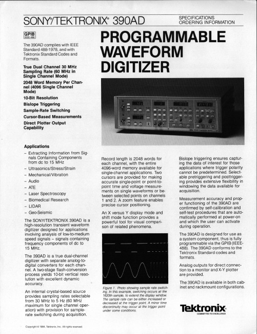
SONY TEKTRONIX 390AD 双通道数字波形捕捉仪说明书
TIME—BASE A AND B
Sample Rate Internal — CH 1 Only: 5 Hz to 60 MHz, 23 steps, 1—2—5 se— quence except 30 MHz and 60 MHz. DUAL: 5 Hz to 30 MHz, 22 steps. External — Normal: 30 MHz maximum. CH 1 ONLY: 60 MHz maximum.
The 390AD is designed for use as a system component, thus is fully programmable via the GPIB (IEEE— 488). The 390AD conforms to the Tektronix Standard codes and formats.
True Dual Channel 30 MHz Sampling Rate (60 MHz in Single Channel Mode) 2048 Word Memory Per Chan— nel (4096 Single Channel Mode) 10—Bit Resolution
Bislope Triggering Sample—Rate Switching
Modes — Auto, Norm, Single. Pretrigger Range CH 1 Only Mode — 0 to 4092. Dual Channel Mode — 0 to 2046.
Posttrigger Range Time Base A
A+B
Vertical Mode
Dual CH 1 only
— Ultrasonics/Stress/Strain
SignalTEK 10G 10G Ethernet Troubleshooter and Band

Why do I need a10G Ethernet T ester?ProblemLAN networks are at risk Solution SignalTEK 10G willAvoid network downtimeTroubleshoot Ethernet connectivity issues faster using diagnostic tools.Pinpoint bottlenecks fasterDiscover which part of your network is causing the bottleneck.Validate network upgradesVerify Multi-Gigabit switch upgrades to 1/2.5/5 and 10Gb/s speeds.Prove the maximum bandwidthProvide “proof of performance” PDF reports to the client.The new SignalTEK 10G measures the maximum bandwidth of the network cabling up to 10 Gigabits per second. Bysimulating actual network traffic users can test, troubleshoot and document network and data cable performance up to 10 Gigabit Ethernet standards.SignalTEK 10G has built-in Wi-Fi connectivity to connect seamlessly to the free AnyWARE Cloud test management system. AnyWARE Cloud offers pre-configuration to eliminate errors on-site, label printer connectivity to save time and “proof of performance” PDF reports for the clients.SignalTEK 10G10G Ethernet Troubleshooter and Bandwidth TesterIncrease your network speedfrom 1Gb/s to 10Gb/sProblemThere are 111 billion metres of Cat5e/Cat6 cabling installed globally that is limited to 1Gb/s bandwidth speeds due to the current switches deployed. Upgrading to Multi-Gigabit switches could increase speed but it is unclear what bandwidth the existing cabling will support.SolutionUse SignalTEK 10G to verify what the data cabling will support (up to 10Gb/s) before spending moneyon new Multi-Gigabit switches delivering2.5/5/10Gb/s speeds. Use the SignalTEK 10G again following the upgrade to prove performance to the client with the “proof of performance” PDF reports.As simple as 1-2-3Easy to understand traffic light status - The simple traffic lightindicator displays Good, Marginal or Poor power level based onIEEE 802.3 1G/10G limits.Max throughput test - The SignalTEK 10G will prove the maximumavailable bandwidth over the fibre link up to 10Gb/s.Discover a faulty SFP – The SFP temperature is measured to helpunderstand if it has become faulty.Will my existing cablinginfrastructure supportMulti-Gigabit technology?10G/Multi-Gigabit Performance90W PoE for AV and Digital SignageTest copper and fibrevertical cablingVoIP testing and troubleshootingMeets your network needs today and tomorrow.The SignalTEK 10G will help to increase network bandwidth without replacing expensive cableinfrastructure, troubleshoot PoE and Ethernet issues and prove the maximum bandwidth up to 10 Gigabits per second.6Testing through Network testing andConduct preventative maintenance testing, audit network capabilities and Prove performance of new cableinstallations up to 10GNetwork T estingThe SignalTEK 10G is also a network tester for troubleshooting and maintenance of active and passive copper and fibre networks.Port & network summary info Press the Autotest button to display summary information and allow for detailed inspection of networkparameters.VLAN detection & operationAutomatic detection of VLAN IDsallows the user to configure SignalTEK10G for operation on a VLAN.Custom WiremapUse a list of wiremap templates forcommon Ethernet cable types aswell as non-Ethernet cables, such asProfinet and ISDN.CDP/LLDP/EDP port informationShow port information using Cisco Discovery Protocol (CPD). Link Layer Discovery Protocol (LLDP) and Extreme Discovery Protocol (EDP).NetscanDisplay list of IP and MAC addressesof every device connected tothe network.72-hour event logFind rogue devices and intermittentissues using the 72-hour event log.SignalTEK 10G logs all network eventsover a 72-hour period to help diagnose connectivity issues faster, reducing hours onsite and reducing trips to the site. Leave the tester onsite, connect remotely tomonitor network activity, view the event log and control all functions of the tester from the office.The SignalTEK 10G will log all network eventsover a 72-hour period to help diagnose connectivity issues faster, reducing hoursonsite and reducing trips to site.72-hour event log captures network events down to the second eliminatingguessworkNo more trial and errorAccurately measure the maximum power available Supports PoE up to 90W (PoE++)Test all PoE Classes (0-8) and Types (af/at/bt)Identifies the powered pairsDetermine whether power is from a switch or mid-span injectorVerify the PoE installationPass / Fail indication to IEEE standards Extended power testSome switches may provide power exceeding their IEEE Class rating. Measure the maximum available power up to 90 watts.PoE T esting.Eliminate GuessworkThe SignalTEK 10Geliminates guesswork when installing, maintaining and troubleshooting wherePoE is deployed up to 90W (PoE++).10Adoption of Power over Ethernet (PoE)In just a few short years we have seen many different applications increasing adopt PoE, such as monitors, digital signage, phones, security cameras, lighting and access control.Previously technicians had to understand all the various standards, device power outputs and cable lengths to be sure a device will operate successfully.The SignalTEK 10G identifies the Class of the PoEsource and power available up to 90W to a PoE device regardless of cable length, cable quality or other factors. A clear pass/fail is provided to IEEE 802.3af/at/bt standards.The SignalTEK 10G identifies the Class of the PoE source and power available up to 90W to a PoE deviceregardless of cable length, cablequality or other factors.11Proof of PerformanceCloud software• Operates anywhere with a web browser – AnyWARE Cloud operates on a PC, Mac and tablet devices (Android and iOS)• Free storage – No need for separate servers or backup systems.• Easy to find project files – Attach all project filesincluding cable layout drawings, videos, and photos into the AnyWARE Cloud. Everything you need in one place. • Share reports easier – Use AnyWARE Cloud to share links to the test reports eliminating the need to manually email large attachments.• Reduce training time with WalkMe – AnyWARE Cloud is embedded with the WalkMe digital adoption platform providing proactive, step-by-step guidance on all key tasks.Fleet management• Easily manage the certifier fleet – Fleet manager allows you to see who has the SignalTEK 10G when the software was last updated and when the results were last synced. Allowing you to manage tester downtime and ensuring results are transferred back to the office and not lost or deleted.Professional PDF reporting• Customer profiles – Create a profile for each of thecustomers with their company logo, address and contact details. This information is automatically pulled through to the reports, saving time.Report formats• Summary report – This is a report showing multiple tests per page.• Detailed report – This is a comprehensive report with all the measurement results with one page per test. Reports can be generated on the SignalTEK 10G or on the free IDEAL AnyWARE Cloud.The AnyWARE Cloudmanagement system allows real time collaboration between Project Managers and Field Technicians. There is no need for Field Technicians to setup the SignalTEK 10G, Project Managers pre-configure thejobs and tests in the AnyWARE Cloud, eliminating potential mistakes and compressing the time taken to prepare reports for customers.Test Management SoftwareIDEAL AnyWARE Cloud Jobs screenIDEAL AnyWARE Cloud Test Result report12ax throughput test up to 10GComplete ConnectivityWi-Fi connectivity to the AnyWARE Cloud management system. USB connection for transferring test dataBuilt-in PDF ReportingReports can be generated directly from the SignalTEK 10G as well as the CloudPartner FinderProvides audible tone and visible indicator when connected tothe remote unitTouchscreenHigh resolution impact resistant touchscreenfor ease of useInternal LoadspeakerAudible tones assist theuser when testingIntuitive UserInterfaceSimplified user interfacefor easy setup andoperationRugged DesignRubberised housing, protected screenand protected measurement portLabel Printer ConnectivityEasily send label IDs to printers for fast and accurate labellingSignalTEK 10GPart NoDescriptionUPGRADE10GFIB UPGRADE SignalTEK 10G - Fibre testing option UPGRADE10GNETUPGRADE SignalTEK 10G - Network testing optionSignalTEK 10G is a future-proof investment as additional features can be unlocked with a simple license key when required. There are two upgrade options to choose from: fibre testing and advanced network testing.Future-proof the investment14Who is SignalTEK 10G designed for?SolutionSignalTEK 10GCT R157000SignalTEK 10GFT R157001SignalTEK 10GNT R157002SignalTEK 10GPRO R157003CategoryDisplays voltage and which pairs have PoEPass / Fail to PoE IEEE standardsMax power available (up to 90 watts)Type (af/at/bt) and Class (1 to 8)P o EF i b r eo p t i o n a lC o p p e rUptime efficiency and 72 hour event log Switch Speed - 100M, 1G, 2.5G, 5G, 10G Testing with packet loss, jitter and delay VLAN, PING, TraceRoute, Hub blink, NetScanProve network performance up to 10GCDP/LLDP/EDP port information N e t w o r ko p t i o n a lPass / Fail to fibre IEEE standards Wiremap, distance to fault, length Optical Tx/Rx power indication Max bandwidth test up to 10Gb/s SFP temperature, vendor and model Cable tracing (with compatible probe)Max bandwidth test up to 10Gb/sData transmission test 1/2.5/5/10GbSupports SFP/SFP+ (MM&SM)Pass / Fail to copper IEEE standardsData transmission test 1/10Gb NbaseT/Multi-Gigabit test 1/2.5/5/10Gb 15Proof of PerformanceIDEAL NETWORKS, SignalTEK and the IDEAL AnyWARE logos are trademarks or registered trademarks of IDEAL INDUSTRIES NETWORKS LIMITED.IDEAL INDUSTRIES NETWORKS LIMITEDStokenchurch House, Oxford Road, Stokenchurch, High Wycombe, Buckinghamshire, HP14 3SX, UK.Tel. +44 (0)1925 428 380 | Fax. +44 (0)1925 428 381********************Specification subject to change without notice. E&OE© IDEAL INDUSTRIES NETWORKS LIMITED 2020Publication no.: 157805 Rev.1SignalTEK 10G10G Ethernet Troubleshooterand Bandwidth TesterOrdering informationOptional Accessories。
Indradrive 系列 故障代码

Error MessagesF9001 Error internal function call.F9002 Error internal RTOS function callF9003 WatchdogF9004 Hardware trapF8000 Fatal hardware errorF8010 Autom. commutation: Max. motion range when moving back F8011 Commutation offset could not be determinedF8012 Autom. commutation: Max. motion rangeF8013 Automatic commutation: Current too lowF8014 Automatic commutation: OvercurrentF8015 Automatic commutation: TimeoutF8016 Automatic commutation: Iteration without resultF8017 Automatic commutation: Incorrect commutation adjustment F8018 Device overtemperature shutdownF8022 Enc. 1: Enc. signals incorr. (can be cleared in ph. 2) F8023 Error mechanical link of encoder or motor connectionF8025 Overvoltage in power sectionF8027 Safe torque off while drive enabledF8028 Overcurrent in power sectionF8030 Safe stop 1 while drive enabledF8042 Encoder 2 error: Signal amplitude incorrectF8057 Device overload shutdownF8060 Overcurrent in power sectionF8064 Interruption of motor phaseF8067 Synchronization PWM-Timer wrongF8069 +/-15Volt DC errorF8070 +24Volt DC errorF8076 Error in error angle loopF8078 Speed loop error.F8079 Velocity limit value exceededF8091 Power section defectiveF8100 Error when initializing the parameter handlingF8102 Error when initializing power sectionF8118 Invalid power section/firmware combinationF8120 Invalid control section/firmware combinationF8122 Control section defectiveF8129 Incorrect optional module firmwareF8130 Firmware of option 2 of safety technology defectiveF8133 Error when checking interrupting circuitsF8134 SBS: Fatal errorF8135 SMD: Velocity exceededF8140 Fatal CCD error.F8201 Safety command for basic initialization incorrectF8203 Safety technology configuration parameter invalidF8813 Connection error mains chokeF8830 Power section errorF8838 Overcurrent external braking resistorF7010 Safely-limited increment exceededF7011 Safely-monitored position, exceeded in pos. DirectionF7012 Safely-monitored position, exceeded in neg. DirectionF7013 Safely-limited speed exceededF7020 Safe maximum speed exceededF7021 Safely-limited position exceededF7030 Position window Safe stop 2 exceededF7031 Incorrect direction of motionF7040 Validation error parameterized - effective thresholdF7041 Actual position value validation errorF7042 Validation error of safe operation modeF7043 Error of output stage interlockF7050 Time for stopping process exceeded8.3.15 F7051 Safely-monitored deceleration exceeded (159)8.4 Travel Range Errors (F6xxx) (161)8.4.1 Behavior in the Case of Travel Range Errors (161)8.4.2 F6010 PLC Runtime Error (162)8.4.3 F6024 Maximum braking time exceeded (163)8.4.4 F6028 Position limit value exceeded (overflow) (164)8.4.5 F6029 Positive position limit exceeded (164)8.4.6 F6030 Negative position limit exceeded (165)8.4.7 F6034 Emergency-Stop (166)8.4.8 F6042 Both travel range limit switches activated (167)8.4.9 F6043 Positive travel range limit switch activated (167)8.4.10 F6044 Negative travel range limit switch activated (168)8.4.11 F6140 CCD slave error (emergency halt) (169)8.5 Interface Errors (F4xxx) (169)8.5.1 Behavior in the Case of Interface Errors (169)8.5.2 F4001 Sync telegram failure (170)8.5.3 F4002 RTD telegram failure (171)8.5.4 F4003 Invalid communication phase shutdown (172)8.5.5 F4004 Error during phase progression (172)8.5.6 F4005 Error during phase regression (173)8.5.7 F4006 Phase switching without ready signal (173)8.5.8 F4009 Bus failure (173)8.5.9 F4012 Incorrect I/O length (175)8.5.10 F4016 PLC double real-time channel failure (176)8.5.11 F4017 S-III: Incorrect sequence during phase switch (176)8.5.12 F4034 Emergency-Stop (177)8.5.13 F4140 CCD communication error (178)8.6 Non-Fatal Safety Technology Errors (F3xxx) (178)8.6.1 Behavior in the Case of Non-Fatal Safety Technology Errors (178)8.6.2 F3111 Refer. missing when selecting safety related end pos (179)8.6.3 F3112 Safe reference missing (179)8.6.4 F3115 Brake check time interval exceeded (181)Troubleshooting Guide | Rexroth IndraDrive Electric Drivesand ControlsI Bosch Rexroth AG VII/XXIITable of ContentsPage8.6.5 F3116 Nominal load torque of holding system exceeded (182)8.6.6 F3117 Actual position values validation error (182)8.6.7 F3122 SBS: System error (183)8.6.8 F3123 SBS: Brake check missing (184)8.6.9 F3130 Error when checking input signals (185)8.6.10 F3131 Error when checking acknowledgment signal (185)8.6.11 F3132 Error when checking diagnostic output signal (186)8.6.12 F3133 Error when checking interrupting circuits (187)8.6.13 F3134 Dynamization time interval incorrect (188)8.6.14 F3135 Dynamization pulse width incorrect (189)8.6.15 F3140 Safety parameters validation error (192)8.6.16 F3141 Selection validation error (192)8.6.17 F3142 Activation time of enabling control exceeded (193)8.6.18 F3143 Safety command for clearing errors incorrect (194)8.6.19 F3144 Incorrect safety configuration (195)8.6.20 F3145 Error when unlocking the safety door (196)8.6.21 F3146 System error channel 2 (197)8.6.22 F3147 System error channel 1 (198)8.6.23 F3150 Safety command for system start incorrect (199)8.6.24 F3151 Safety command for system halt incorrect (200)8.6.25 F3152 Incorrect backup of safety technology data (201)8.6.26 F3160 Communication error of safe communication (202)8.7 Non-Fatal Errors (F2xxx) (202)8.7.1 Behavior in the Case of Non-Fatal Errors (202)8.7.2 F2002 Encoder assignment not allowed for synchronization (203)8.7.3 F2003 Motion step skipped (203)8.7.4 F2004 Error in MotionProfile (204)8.7.5 F2005 Cam table invalid (205)8.7.6 F2006 MMC was removed (206)8.7.7 F2007 Switching to non-initialized operation mode (206)8.7.8 F2008 RL The motor type has changed (207)8.7.9 F2009 PL Load parameter default values (208)8.7.10 F2010 Error when initializing digital I/O (-> S-0-0423) (209)8.7.11 F2011 PLC - Error no. 1 (210)8.7.12 F2012 PLC - Error no. 2 (210)8.7.13 F2013 PLC - Error no. 3 (211)8.7.14 F2014 PLC - Error no. 4 (211)8.7.15 F2018 Device overtemperature shutdown (211)8.7.16 F2019 Motor overtemperature shutdown (212)8.7.17 F2021 Motor temperature monitor defective (213)8.7.18 F2022 Device temperature monitor defective (214)8.7.19 F2025 Drive not ready for control (214)8.7.20 F2026 Undervoltage in power section (215)8.7.21 F2027 Excessive oscillation in DC bus (216)8.7.22 F2028 Excessive deviation (216)8.7.23 F2031 Encoder 1 error: Signal amplitude incorrect (217)VIII/XXII Bosch Rexroth AG | Electric Drivesand ControlsRexroth IndraDrive | Troubleshooting GuideTable of ContentsPage8.7.24 F2032 Validation error during commutation fine adjustment (217)8.7.25 F2033 External power supply X10 error (218)8.7.26 F2036 Excessive position feedback difference (219)8.7.27 F2037 Excessive position command difference (220)8.7.28 F2039 Maximum acceleration exceeded (220)8.7.29 F2040 Device overtemperature 2 shutdown (221)8.7.30 F2042 Encoder 2: Encoder signals incorrect (222)8.7.31 F2043 Measuring encoder: Encoder signals incorrect (222)8.7.32 F2044 External power supply X15 error (223)8.7.33 F2048 Low battery voltage (224)8.7.34 F2050 Overflow of target position preset memory (225)8.7.35 F2051 No sequential block in target position preset memory (225)8.7.36 F2053 Incr. encoder emulator: Pulse frequency too high (226)8.7.37 F2054 Incr. encoder emulator: Hardware error (226)8.7.38 F2055 External power supply dig. I/O error (227)8.7.39 F2057 Target position out of travel range (227)8.7.40 F2058 Internal overflow by positioning input (228)8.7.41 F2059 Incorrect command value direction when positioning (229)8.7.42 F2063 Internal overflow master axis generator (230)8.7.43 F2064 Incorrect cmd value direction master axis generator (230)8.7.44 F2067 Synchronization to master communication incorrect (231)8.7.45 F2068 Brake error (231)8.7.46 F2069 Error when releasing the motor holding brake (232)8.7.47 F2074 Actual pos. value 1 outside absolute encoder window (232)8.7.48 F2075 Actual pos. value 2 outside absolute encoder window (233)8.7.49 F2076 Actual pos. value 3 outside absolute encoder window (234)8.7.50 F2077 Current measurement trim wrong (235)8.7.51 F2086 Error supply module (236)8.7.52 F2087 Module group communication error (236)8.7.53 F2100 Incorrect access to command value memory (237)8.7.54 F2101 It was impossible to address MMC (237)8.7.55 F2102 It was impossible to address I2C memory (238)8.7.56 F2103 It was impossible to address EnDat memory (238)8.7.57 F2104 Commutation offset invalid (239)8.7.58 F2105 It was impossible to address Hiperface memory (239)8.7.59 F2110 Error in non-cyclical data communic. of power section (240)8.7.60 F2120 MMC: Defective or missing, replace (240)8.7.61 F2121 MMC: Incorrect data or file, create correctly (241)8.7.62 F2122 MMC: Incorrect IBF file, correct it (241)8.7.63 F2123 Retain data backup impossible (242)8.7.64 F2124 MMC: Saving too slowly, replace (243)8.7.65 F2130 Error comfort control panel (243)8.7.66 F2140 CCD slave error (243)8.7.67 F2150 MLD motion function block error (244)8.7.68 F2174 Loss of motor encoder reference (244)8.7.69 F2175 Loss of optional encoder reference (245)Troubleshooting Guide | Rexroth IndraDrive Electric Drivesand Controls| Bosch Rexroth AG IX/XXIITable of ContentsPage8.7.70 F2176 Loss of measuring encoder reference (246)8.7.71 F2177 Modulo limitation error of motor encoder (246)8.7.72 F2178 Modulo limitation error of optional encoder (247)8.7.73 F2179 Modulo limitation error of measuring encoder (247)8.7.74 F2190 Incorrect Ethernet configuration (248)8.7.75 F2260 Command current limit shutoff (249)8.7.76 F2270 Analog input 1 or 2, wire break (249)8.7.77 F2802 PLL is not synchronized (250)8.7.78 F2814 Undervoltage in mains (250)8.7.79 F2815 Overvoltage in mains (251)8.7.80 F2816 Softstart fault power supply unit (251)8.7.81 F2817 Overvoltage in power section (251)8.7.82 F2818 Phase failure (252)8.7.83 F2819 Mains failure (253)8.7.84 F2820 Braking resistor overload (253)8.7.85 F2821 Error in control of braking resistor (254)8.7.86 F2825 Switch-on threshold braking resistor too low (255)8.7.87 F2833 Ground fault in motor line (255)8.7.88 F2834 Contactor control error (256)8.7.89 F2835 Mains contactor wiring error (256)8.7.90 F2836 DC bus balancing monitor error (257)8.7.91 F2837 Contactor monitoring error (257)8.7.92 F2840 Error supply shutdown (257)8.7.93 F2860 Overcurrent in mains-side power section (258)8.7.94 F2890 Invalid device code (259)8.7.95 F2891 Incorrect interrupt timing (259)8.7.96 F2892 Hardware variant not supported (259)8.8 SERCOS Error Codes / Error Messages of Serial Communication (259)9 Warnings (Exxxx) (263)9.1 Fatal Warnings (E8xxx) (263)9.1.1 Behavior in the Case of Fatal Warnings (263)9.1.2 E8025 Overvoltage in power section (263)9.1.3 E8026 Undervoltage in power section (264)9.1.4 E8027 Safe torque off while drive enabled (265)9.1.5 E8028 Overcurrent in power section (265)9.1.6 E8029 Positive position limit exceeded (266)9.1.7 E8030 Negative position limit exceeded (267)9.1.8 E8034 Emergency-Stop (268)9.1.9 E8040 Torque/force actual value limit active (268)9.1.10 E8041 Current limit active (269)9.1.11 E8042 Both travel range limit switches activated (269)9.1.12 E8043 Positive travel range limit switch activated (270)9.1.13 E8044 Negative travel range limit switch activated (271)9.1.14 E8055 Motor overload, current limit active (271)9.1.15 E8057 Device overload, current limit active (272)X/XXII Bosch Rexroth AG | Electric Drivesand ControlsRexroth IndraDrive | Troubleshooting GuideTable of ContentsPage9.1.16 E8058 Drive system not ready for operation (273)9.1.17 E8260 Torque/force command value limit active (273)9.1.18 E8802 PLL is not synchronized (274)9.1.19 E8814 Undervoltage in mains (275)9.1.20 E8815 Overvoltage in mains (275)9.1.21 E8818 Phase failure (276)9.1.22 E8819 Mains failure (276)9.2 Warnings of Category E4xxx (277)9.2.1 E4001 Double MST failure shutdown (277)9.2.2 E4002 Double MDT failure shutdown (278)9.2.3 E4005 No command value input via master communication (279)9.2.4 E4007 SERCOS III: Consumer connection failed (280)9.2.5 E4008 Invalid addressing command value data container A (280)9.2.6 E4009 Invalid addressing actual value data container A (281)9.2.7 E4010 Slave not scanned or address 0 (281)9.2.8 E4012 Maximum number of CCD slaves exceeded (282)9.2.9 E4013 Incorrect CCD addressing (282)9.2.10 E4014 Incorrect phase switch of CCD slaves (283)9.3 Possible Warnings When Operating Safety Technology (E3xxx) (283)9.3.1 Behavior in Case a Safety Technology Warning Occurs (283)9.3.2 E3100 Error when checking input signals (284)9.3.3 E3101 Error when checking acknowledgment signal (284)9.3.4 E3102 Actual position values validation error (285)9.3.5 E3103 Dynamization failed (285)9.3.6 E3104 Safety parameters validation error (286)9.3.7 E3105 Validation error of safe operation mode (286)9.3.8 E3106 System error safety technology (287)9.3.9 E3107 Safe reference missing (287)9.3.10 E3108 Safely-monitored deceleration exceeded (288)9.3.11 E3110 Time interval of forced dynamization exceeded (289)9.3.12 E3115 Prewarning, end of brake check time interval (289)9.3.13 E3116 Nominal load torque of holding system reached (290)9.4 Non-Fatal Warnings (E2xxx) (290)9.4.1 Behavior in Case a Non-Fatal Warning Occurs (290)9.4.2 E2010 Position control with encoder 2 not possible (291)9.4.3 E2011 PLC - Warning no. 1 (291)9.4.4 E2012 PLC - Warning no. 2 (291)9.4.5 E2013 PLC - Warning no. 3 (292)9.4.6 E2014 PLC - Warning no. 4 (292)9.4.7 E2021 Motor temperature outside of measuring range (292)9.4.8 E2026 Undervoltage in power section (293)9.4.9 E2040 Device overtemperature 2 prewarning (294)9.4.10 E2047 Interpolation velocity = 0 (294)9.4.11 E2048 Interpolation acceleration = 0 (295)9.4.12 E2049 Positioning velocity >= limit value (296)9.4.13 E2050 Device overtemp. Prewarning (297)Troubleshooting Guide | Rexroth IndraDrive Electric Drivesand Controls| Bosch Rexroth AG XI/XXIITable of ContentsPage9.4.14 E2051 Motor overtemp. prewarning (298)9.4.15 E2053 Target position out of travel range (298)9.4.16 E2054 Not homed (300)9.4.17 E2055 Feedrate override S-0-0108 = 0 (300)9.4.18 E2056 Torque limit = 0 (301)9.4.19 E2058 Selected positioning block has not been programmed (302)9.4.20 E2059 Velocity command value limit active (302)9.4.21 E2061 Device overload prewarning (303)9.4.22 E2063 Velocity command value > limit value (304)9.4.23 E2064 Target position out of num. range (304)9.4.24 E2069 Holding brake torque too low (305)9.4.25 E2070 Acceleration limit active (306)9.4.26 E2074 Encoder 1: Encoder signals disturbed (306)9.4.27 E2075 Encoder 2: Encoder signals disturbed (307)9.4.28 E2076 Measuring encoder: Encoder signals disturbed (308)9.4.29 E2077 Absolute encoder monitoring, motor encoder (encoder alarm) (308)9.4.30 E2078 Absolute encoder monitoring, opt. encoder (encoder alarm) (309)9.4.31 E2079 Absolute enc. monitoring, measuring encoder (encoder alarm) (309)9.4.32 E2086 Prewarning supply module overload (310)9.4.33 E2092 Internal synchronization defective (310)9.4.34 E2100 Positioning velocity of master axis generator too high (311)9.4.35 E2101 Acceleration of master axis generator is zero (312)9.4.36 E2140 CCD error at node (312)9.4.37 E2270 Analog input 1 or 2, wire break (312)9.4.38 E2802 HW control of braking resistor (313)9.4.39 E2810 Drive system not ready for operation (314)9.4.40 E2814 Undervoltage in mains (314)9.4.41 E2816 Undervoltage in power section (314)9.4.42 E2818 Phase failure (315)9.4.43 E2819 Mains failure (315)9.4.44 E2820 Braking resistor overload prewarning (316)9.4.45 E2829 Not ready for power on (316)。
MORNSUN LS08-13BxxSS系列AC DC电源说明书
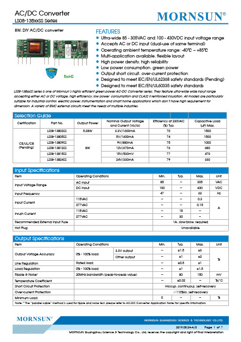
8W,DIY AC/DC converterRoHSFEATURES●Ultra-wide 85-305VAC and 100-430VDC input voltage range ●Accepts AC or DC input (dual-use of same terminal)●Operating ambient temperature range:-40℃~+85℃●Multi-application available,flexible layout ●High power density,high reliability●Low power consumption,green power●Output short circuit,over-current protection●Designed to meet IEC/EN/UL62368safety standards (Pending)●Designed to meet IEC/EN/UL60335safety standardsLS08-13BxxSS series is one of Mornsun’s highly efficient green power AC-DC Converter series.They feature ultra-wide wide input rangeaccepting either AC or DC voltage,high efficiency,low power consumption and CLASS II reinforced insulation.All models are particularly suitable for industrial control,electric power,instrumentation and smart home applications which don’t have high requirement for dimension.A variety of EMC external circuits meet the needs of multiple industries.Input SpecificationsItemOperating Conditions Min.Typ.Max.Unit Input Voltage Range AC input 85--305V AC DC input100--430VDC Input Frequency 47--63HzInput Current 115V AC ----0.3A 277V AC ----0.15Inrush Current115V AC --15--277V AC--30--Recommended External Input Fuse 1A,slow-blow,requiredHot PlugUnavailableOutput SpecificationsItemOperating Conditions Min.Typ.Max.UnitOutput Voltage Accuracy 0%-100%load 3.3V output --±1.5±3%Other output--±1±2Line Regulation Rated load --±0.5±1Load Regulation 0%-100%load--±1±1.5Ripple &Noise *20MHz bandwidth (peak-to-peak value)--80150mV Temperature Coefficient --±0.02--%/°C Short Circuit Protection Hiccup,continuous,self-recoveryOver-current Protection ≥110%Io,self-recoveryMinimum Load----%Note:*The “parallel cable”method is used for ripple and noise test,please refer to AC-DC Converter Application Notes for specific information.Selection GuideCertificationPart No.Output PowerNominal Output Voltage and Current (Vo/Io)Efficiency at 230V AC(%)Typ.Capacitive Load(µF)Max.CE/UL/CB (Pending)LS08-13B03SS 5.28W3.3V/1600mA 701500LS08-13B05SS8W 5V/1600mA 741500LS08-13B09SS 9V/880mA 751000LS08-13B12SS 12V/670mA 76680LS08-13B15SS 15V/530mV 77470LS08-13B24SS24V/330mA79330General SpecificationsItem Operating Conditions Min.Typ.Max.UnitIsolation Test Input-output Electric Strength Test for1min.,(leakage current<5mA)3000----VACOperating Temperature-40--+85℃Storage Temperature-40--+105Storage Humidity----95%RHPower Derating -40℃~-25℃ 2.67----%/℃+55℃~+85℃ 2.5----85V AC-100VAC1----277V AC-305V AC0.54----Safety Standard IEC/EN/UL62368,IEC/EN/UL60335 Safety Certification IEC/EN/UL62368(Pending) Safety CLASS CLASS IIMTBF MIL-HDBK-217F@25°C>300,000h Mechanical SpecificationsCase Material44.50x24.00x15.00mmWeight11g(Typ.)Cooling method Free air convectionElectromagnetic Compatibility(EMC)Emissions CECISPR32/EN55032CLASS A(Recommended circuit1,4)CISPR32/EN55032CLASS B(Recommended circuit2,3) RECISPR32/EN55032CLASS A(Recommended circuit1,4)CISPR32/EN55032CLASS B(Recommended circuit2,3)Immunity ESD IEC/EN61000-4-2Contact±6KV Perf.Criteria B RS IEC/EN61000-4-310V/m perf.Criteria AEFTIEC/EN61000-4-4±2KV(Recommended circuit1,2)perf.Criteria BIEC/EN61000-4-4±4KV(Recommended circuit3,4)perf.Criteria B SurgeIEC/EN61000-4-5line to line±1KV(Recommended circuit1,2)perf.Criteria BIEC/EN61000-4-5line to line±2KV(Recommended circuit3,4)IEC/EN61000-4-5line to line±4KV(Recommended circuit4)perf.Criteria B CS IEC/EN61000-4-610Vr.m.s perf.Criteria A Voltage dips,shortinterruptions and voltagevariations immunityIEC/EN61000-4-110%,70%perf.Criteria BProduct Characteristic CurveNote:①With an AC input between85-100VAC/277-305VAC and a DC input between100-120VDC/390-430VDC,the output power must be derated as per temperature derating curves;②This product is suitable for applications using natural air cooling;for applications in closed environment please consult factory or one of our FAE.Additional Circuits Design ReferenceLS series additional circuits design referenceLS08series additional components selection guidePart No.FUSE(required)C1required)C2(required)L1(required)C3(required )C4CY1(required )LS08-13B03SS 1A/300V22µF/450V470µF/16V(solid-state capacitor) 4.7µH 150µF/35V 0.1µF/50V1.0nF/400V ACLS08-13B05SS LS08-13B09SS 220µF/16V(solid-state capacitor)100µF/35V LS08-13B12SS LS08-13B15SS 470uF/35V 47µF/35VLS08-13B24SS220uF/35VNote:1.C1:input capacitors,C2:output storage capacitors,they must be connected externally.2.We recommend using an electrolytic capacitor with high frequency and low ESR rating for C3(refer to manufacture’s datasheet).Combined with C2,L1,they form a pi-type filter circuit.Choose a capacitor voltage rating with at least 20%margin,in other words not exceeding 80%.C4is a ceramic capacitor,used for filtering high frequency noise.A suppressor diode (TVS)is a recommended to protect the application in case of a converter failure and specification should be 1.2times of the output voltage.Immunity design circuits for referenceEmissions design circuits for referenceCLASS ⅢCLASS ⅣCLASS ACLASS BEnvironmental Application EMC SolutionLS series environmental application EMC solution selection tableRecommendedcircuit Application environmental Typical industryInput voltagerangeEnvironment temperature Emissions Immunity 1Basic applicationNone85~305V AC -40℃~+85℃CLASS A CLASS Ⅲ2Indoor civil environment Smart home/Home appliances(2Y)-25℃~+55℃CLASS BCLASS ⅢIndoor general environment Intelligent building/Intelligentagriculture 3Indoor industrial environment Manufacturing workshop -25℃~+55℃CLASS B CLASS Ⅳ4Outdoor general environmentITS/Video monitoring/Charging point/Communication/Securityand protection-40℃~+85℃CLASS ACLASS ⅣOutdoor harsh environmentOn-line power meter Communication base station-40℃~+85℃CLASS A>CLASS ⅣSurge:line to ground ±4KV EFT:CLASS ⅣElectromagnetic Compatibility Solution--Recommended Circuit1.Recommended circuit 1——Basic applicationrecommended circuit 1Application environmentalAmbient temperature rangeImmunity CLASSEmissions CLASSBasic application-40℃~+85℃CLASS ⅢCLASS AComponentRecommended valueR112Ω/3W LDM4.7mH2.Recommended circuit 2——Indoor civil /Universal system recommended circuits for general environmentRecommended circuit 2Application environmentalAmbient temperature rangeImmunity CLASSEmissions CLASS Indoor civil /general -25℃~+55℃CLASS ⅢCLASS BComponentRecommended valueR112Ω/3W CY1(CY2) 1.0nF/400V ACLCM 3.5mH LDM 0.33mH CX0.1µF/310VAC FUSE (required)1A/300V ,slow-blowNote:In the home appliance application environment,the two Y capacitors of the primary and secondary need to be externally connected (CY1/CY2,value at 2.2nF/400VAC),which can meet the EN60335certification.In other industries,only one Y capacitor is needed.3.Recommended circuit 3——Universal system recommended circuits for indoor industrial environmentRecommended circuit 3Application environmental Ambienttemperature rangeImmunity CLASSEmissions CLASSIndoor industrial-25℃~+55℃CLASS ⅣCLASS BComponentRecommended valueMOV S14K350C1450V/22uF CY1 2.2nF/400V AC CX 0.1µF/310V ACLCM 3.5mH LDM 0.33mH R112Ω/3WFUSE (required)2A/300V ,slow-blow4.Recommended circuit 4——Universal system recommended circuits for outdoor general/harsh environmentRecommended circuit 4Application environmental Ambienttemperature rangeImmunity CLASSEmissions CLASSOutdoor general environment-40℃~+85℃CLASS ⅣCLASS AComponentRecommended valueMOV S14K350C1450V/22uF LDM 4.7mH R112Ω/3WFUSE (required)2A/300V ,slow-blowApplication environmental Ambient temperaturerangeImmunity CLASS EmissionsCLASSOutdoor harsh environment -40℃~+85℃>CLASSⅣSurge:line to ground±4KVEFT:CLASSⅣCLASS AComponent Recommended valueMOV S20K350C1450V/33uF(Surge protection priority)LDM 4.7mHR133Ω/5WFUSE(required) 6.3A/300V,slow-blow5.For additional information please refer to application notes on . LS08-13BxxSS Dimensions and Recommended LayoutNote:1.For additional information on Product Packaging please refer to .Packaging bag number:58220032;2.External electrolytic capacitors are required to modules,more details refer to typical applications;3.This part is open frame,at least6.4mm safety distance between the primary and secondary external components of the module isneeded to meet the safety requirement;4.Unless otherwise specified,parameters in this datasheet were measured under the conditions of Ta=25℃,humidity<75%,nominal inputvoltage(115V and230V)and rated output load;5.In order to improve the efficiency at light load,there will be audible noise generated,but it does not affect product performance andreliability;6.Module required dispensing fixed after assembled;7.All index testing methods in this datasheet are based on our company corporate standards;8.We can provide product customization service,please contact our technicians directly for specific information;9.Products are related to laws and regulations:see"Features"and"EMC";10.Our products shall be classified according to ISO14001and related environmental laws and regulations,and shall be handled byqualified units.Mornsun Guangzhou Science&Technology Co.,Ltd.Address:No.5,Kehui St.1,Kehui Development Center,Science Ave.,Guangzhou Science City,Huangpu District,Guangzhou,P.R.China Tel:86-20-38601850Fax:86-20-38601272E-mail:***************。
AP8831、AP8830、AP8830J、AP8833J、AP7800、AP7801、AP7802

Voltage Mounting U-space
Nominal Region Voltage
Input Nominal Input Plug Circuit Power Type
Output Receptacles
Cord APC SKU Length
Vertical, 0U Vertical, 0U Vertical, 0U Vertical, 0U Vertical, 0U Vertical, 0U Horizontal, 1U Horizontal, 1U Horizontal, 2U Horizontal, 2U
100 – 120 V Input
200 – 240 V Input
Metered Rack PDUs
Metered Rack PDUs provide real-time remote monitoring of connected loads. User-defined alarms warn of potential circuit overloads before critical IT failures occur.
(16) C13 (18) C13 (18) C13 (18) C13
(36)C13
(16) 5-20 (2) C19 (36)C13
(8) C13 (8) C13 (12) C13 (12) C13
(2) C19 (2) C19 (2) C19 (6) C19 (12) (6) C19
(4) C19 (4) C19
IEC-309 16 A
Vertical, 0U 100 – 240 NAM, LAM 20 A
GCN, APJ
3.3 kW
NEMA L6-20P
TDK-Lambda HWS1500 HD模型电源说明书
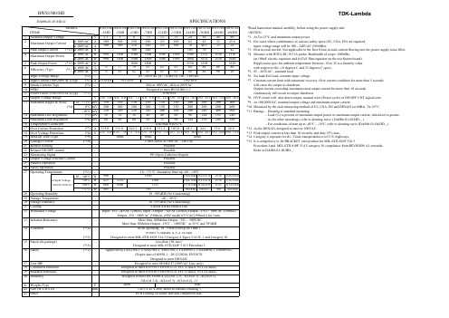
HWS1500/HDTDK-Lambda*Read instruction manual carefully, before using the power supply unit. =NOTES=*1.At Ta=25°C and maximum output power.*2.For cases where conformance to various safety specs (UL, CSA, EN) are required,input voltage range will be 100 - 240VAC (50/60Hz).*3.First in-rush current. Not applicable to the first 0.2ms in-rush current flowing into the power supply noise filter.*4.Measure with JEITA RC-9131A probe, Bandwidth of scope :100MHz.(at 100uF electric capacitor and 0.47uF film capacitor on the test fixture board.)Ripple noise spec for ambient temperature between -10 to 25 is a linearity value with respect to the -10 degrees C and 25 degrees C specs.*5.85 - 265VAC , constant load.*6.No load-Full load, constant input voltage.*7.Constant current limit with automatic recovery. Over current condition for more than 5 secondswill cause the output to shutdown.Output current exceeding maximum rated output current for more then 10 seconds continuously will result to output shutdown.*8.OVP circuit will shut down output, manual reset (Power cycle) or ON/OFF CNT signal reset.*9.At 100/200VAC, nominal output voltage and maximum output current.*10.Measured by the each measuring method of UL, CSA, EN and DENAN (at 60Hz), Ta=25°C. *11.Ratings - Derating at standard mounting.- Load (%) is percent of maximum output power or maximum output current, whichever is greater. - As for other mountings, refer to derating curve ( DA006-01-02/HD-_ ).- For conditions of start up at -40°C - -10°C, refer to derating curve (DA006-01-04/HD-_).*12.As for DENAN, designed to meet at 100VAC.*13.Peak output current is less than 10 seconds, and duty 35% max.*14.Category 4 exposure levels : Track transportation over U.S. highways.*15.It is compulsory to fix BRACKET onto product for MIL-STD-810F 516.5Procedure I and MIL-STD-810F 514.5 category 10 compliance from REVISION A1 onwards.Refer to DA006-01-06/HD-_.SPECIFICATIONSDA006-01-01/HD-GHWS1500/HD TDK-LambdaOUTPUT DERATINGHWS1500/HD TDK-LambdaHWS1500/HD TDK-Lambda。
Switching Mode Power Supply 规格书说明书
1
SWITCHING MODE POWER SUPPLY SPECIFICATION
E.C.LIST/变更履历表
Rev.
版本
Description of Change/变更内容描述
Before/变更前
After/变更后
01 Original Release(初次发行)
Changed Operator/ Date/日期 执行者
3 Output Characteristics/输出特性…………………………………………………...…………….…. ……….….….….....5
3.1 Static Output Characteristics <Vo & R+N>/静态输出特性………..……...….…….…. ……….….…….…..…....5 3.2 Line / Load Regulation/线性/负载调整率…...………….……………..……………….…. …….….…….….. .….5 3.3 Turn on Delay Time/开机延迟时间…………………………………….…………. ………….….….….…….…..…5 3.4 Hold up Time/关机维持时间…………………………………………………..……….…. ……….….…….…..…...5 3.5 Capacitance Load/容性负载………………………………………………………..……….…. …….….…….……5 3.6 Output Overshoot / Undershoot/输出过冲/欠冲……………………………………….….…….…..….….……....5 3.7 Output Load Transient Response/输出负载瞬态响应…..…………….……………….….…….…..……….…….5
TAISAW(台湾嘉硕)料号汇总
0.8 6 6 4.0 20 5 4 1.1 4 0.25 16 4 3 3 3 3 3 1.15 1.0 16 1 8 5 5 20 5 18 20 2 18 2 0.138 1.03 5 5 2 4 20 8.0 8.0 20 0.5 0.5 3.2 4.0 0.6 4.0 0.6
3.5 3.5 3.5 4.0 3.5 3 3 4.0 3.0 4.0 3.0 4.5 3.0 3.5 2.5 2.5 2.5 4.0 3.0 2.8 3.8 4.5 3.6 3.6 4.2 3.6 2.8 3.5 3.0 2.8 4 3.5 3 3.6 3.6 4 3.6 4.2 4.5 4.5 2.8 4.0 5.0 4 3.5 4.0 3.5 4.0
TA0283A TA0797A TA1002A TA0188A TE0113A TA0964A TA1346A TA0376A TA0559A TA0971A TA0875A TA0980A TA0489A TA0529A TA0997A TA0520A TA1135A TA0309A TA0340A TA0417A TA0396A TA0701A TA0525A TA0526A TA1119A TA0592A TA0311A TA0409A TA1105A TA0418A TA0706A TA0192A TA1216A TA0527A TA0593A TA0707A TA0655A TA1118A TA433K1 TA0286A TA0692A TA0293A TA0723A TA0708A TA0278A TA0264A TA0255A TA0277A
315.5 340 340 343.5 360 387.5 388 390 394 400 402 402 403.5 403.5 403.5 403.5 403.5 403.55 403.966 408.5 413.9 414 415.4 415.4 416 416.405 420 420 423 424 426 426.1 426.44 427.8 428.835 429.25 430 431 433 433 433 433.42 433.42 433.5 433.92 433.92 433.92 433.92
ODS-1500三相电源测试器说明书
EN ArrayGENERAL FEATURES:•Sine wave output voltage•Selectable output frequency: 50/60Hz•Adjustable output voltage•High input-output isolation 3000Vrms•Remote inhibit•Three-phase synchronization•Remote control via RS232•Alarm by isolated relay contacts•Remote off opto-coupled•Optional railway version EN50155•Fire and smoke: EN45545-2approvedCONECTIONSBLOCK DIAGRAMRS232 functions MonitoringInput voltage Output voltage Output currentInternal temperature Output frequency Output power SettingsInput undervoltagelockoutInput under voltaje alarmOn / Off Output frequency Maximum ouput currentOutput voltageConnections for a three phase systemDIMENSIONSDESCRIPTIONThe ODS-1500 consists of single phase sine-wave DC/AC inverters with galvanic isolation between input and output The unit allows:• Select 50 / 60Hz by means of DIP-switch.• Select local / remote (RS-232) by means of DIP-switch • Shutdown applying voltage on pins 3 and 4 of signal connector • Connect three units in ”Y” three phase way• Local signalization of Output OK by means of green LED • Local alarm. Red LED ON when:• Output voltage is not OK• Output current >OUTPUT CURRENT ALARM • Input voltage out of margins•Unit shutdowns by overcurrent or remote OFF• Remote alarm. Open contacts when output voltage is not OK • Set and monitor parameters via RS-232.The ODS-1500 are equipped with a maximum average power protection as well as maximum output peak current protection. This protects the unit even when an output short-circuit occurs. It also features a disable function for input under-voltage, which allows protecting the batteries from harmful discharges. START-UP • The unit has 6 threaded holes for the fixation on a mounting surface. •The unit has internal fans. For an appropriate cooling, the air input and output should be free of elements that cause and an air flow reduction (minimum recommended distance to other objects 50mm). • Make connections as shown in the figure.•The default output frequency is 50Hz. For 60Hz simply actuate the dip-switch as indicated in the figure.For safety reasons, the following requirements must be met:•Provide the equipment with some kind of protective enclosure that complies with the electrical safety directives in effect within the country where the equipment is installed.• Include an input fuse with a rating immediately higher than the maximum input current.•Use cables of adequate cross-section to connect inputs and outputs. The following table lists the maximum currents and the minimum cross-sections for the cables used for each power connection.Maximum depth for the 6 screws M4: 3.5mm2601- 409 ACCESSORIES CODE Signals female connector2601-409Mounting brackets kitContains baseplateNP-9282 DIN rail assembly kitScrews includedNP-93392U 19" rackmount tray kit. It allows toinstall one or two unitsNP-9353NP-9282NP-9339NP-9353RS 232 communicationsWORKING PARAMETERSInternal restart temperature after over-temperature shutdown 75 ºC Input voltage parameters 71X1 71X3 71X4 71X5 71X6 71X7 Max. input voltage shutdown instantaneous 16.8 33.7 50.6 67.3 100.9 154.1 Vdc Max. input voltage shutdown timed 0.1s 15.1 30.1 45.2 60.1 90.1 138.6 Vdc Maximum star-up voltage 14.9 29.9 44.9 59.8 89.7 137.4 Vdc Minimum star-up voltage 10.6 17.9 26.9 35.9 53.9 82.4 Vdc Min. input voltage shutdown timed 0.1s 10.0 16.7 25.1 33.5 50.3 76.9 Vdc Min. input voltage shutdown instantaneous 9.6 14.4 21.6 28.7 43.1 65.9 Vdc Output voltage parameters711X712XOutput voltage of short circuit or deep overload < 164 < 86 Vac Time of short-circuit 1000 ms Time of start-up after shutdown by short-circuit 2000 ms Number of start-up attempts after a short circuit 3Output current parameters 7111 7113/4/5/6/7 7121 7123/4/5/6/7 Maximum continuous output current 5.3 6.6 10.1 12.7 A Warning current 5.2 6.5 10 12.5 A Maximum overload I2t See figure belowStart-up time after shutdown by overload 1000 1500 1000 2000 ms Number of attempts of consecutive overload 3Start-up and working errors 71XXLock to continuous overload or internal failure unlimitedMinimum time between disconnection and another connection 2 minOVERLOAD PROTECTIONProtection against overloads and short-circuits By current limiting at IopkBy I²t. The unit shutdowns when the current-time is over the continuous operation curveOverload protection recovery Every 2 seconds after shutdown, the unit tries to restart up to 3 times. If the overload persists, the unit reminds shutdown until an input reconnection.ShutdownArea1000s100s10s1s105 115 130 145 160 175 190 205 220 235 250%IonomCurrentLimit(Iopk)ContinuousOperationEU DECLARATION OF CONFORMITYThe undersigned, representing the following:Manufacturer: PREMIUM, S. A.,Address: C/. DolorsAleu 19-21, 2º 2ª 08908 L’Hospitalet de Llobregat, SPAINherewith declares that the product:Type: DC/AC InverterModels: ODS-750 -7111 -7113 -7115 -7116 -7117 -7121 -7123 -7125 -7126 -7127is in conformity with the provisions of the following EU directive(s):2014/35/EU Low voltage2014/30/EU Electromagnetic compatibilityand that standards and/or technical specifications referenced overleaf have been applied:EN 60950: 2005 Safety (Information technology equipment)EN 61000-6-3: 2007 Generic emission standardEN 61000-6-2: 2005 Generic Immunity standardEN 50155: 2007Railway applications. Electronic equipmentused on rolling stock materialEN 50121-3-2: 2015Railway applications. EMC Rolling stockequipmentCE markingyear: 2010For the fulfillment of this declaration the product must be used only for the aim that has been conceived, considering the limitations established in the instructions manual or datasheet.L’Hospitalet de Llobregat, 20-02-2017PREMIUM S.A. is an ISO9001 certified company by Bureau Veritas Jordi GazoManaging DirectorANEXO / ANNEX。
Eaton 281307 电容电路保护器数据表说明书
Eaton 281307Eaton Moeller series NZM - Molded Case Circuit Breaker. Circuit-breaker, 3p, 125A, H2-M125Allgemeine spezifikationEaton Moeller series NZM molded case circuit breaker thermo-magnetic281307149 mm184 mm 105 mm 2.334 kg RoHS conform IEC IEC/EN 609474015082813079NZMH2-M125Product NameCatalog NumberProduct Length/Depth Product Height Product Width Product Weight Compliances Certifications EANModel Code125 AIs the panel builder's responsibility. The specifications for the switchgear must be observed.5 kA130 kAMeets the product standard's requirements.Is the panel builder's responsibility. The specifications for the switchgear must be observed.Built-in device fixed built-in techniqueFixed125 ADoes not apply, since the entire switchgear needs to be evaluated.Min. 2 segments of 9 mm x 0.8 mm at box terminalMax. 8 segments of 24 mm x 1 mm (2x) at box terminal Max. 10 segments of 16 mm x 0.8 mm at box terminalMax. 10 segments of 24 mm x 0.8 mm at rear-side connection (punched)Min. 2 segements of 16 mm x 0.8 mm at rear-side connection (punched)Rocker leverMeets the product standard's requirements.40 °C eaton-circuit-breaker-let-through-current-nzm-mccb-characteristic-curve-005.epseaton-circuit-breaker-characteristic-power-defense-mccb-characteristic-curve-037.epsMH2-M125il01206006z2015_11.pdfDas neue digitale NZM-Sortiment - In Kurze verfugbar DE Vorstellung des neuen digitalen Leistungsschalter NZMDA-CD-nzm2_3pDA-CS-nzm2_3peaton-manual-motor-starters-starter-msc-r-reversing-starter-wiring-diagram.epseaton-manual-motor-starters-starter-nzm-mccb-wiring-diagram.epseaton-nzm-technical-information-sheeteaton-circuit-breaker-nzm-mccb-dimensions-019.epsRated operational current for specified heat dissipation (In) 10.11 Short-circuit ratingRated short-circuit breaking capacity Ics (IEC/EN 60947) at 690 V, 50/60 HzRated short-circuit breaking capacity Icu (IEC/EN 60947) at 400/415 V, 50/60 Hz10.4 Clearances and creepage distances10.12 Electromagnetic compatibilityMounting MethodAmperage Rating10.2.5 LiftingTerminal capacity (copper strip)Handle type10.2.3.1 Verification of thermal stability of enclosuresAmbient storage temperature - min Characteristic curveeCAD model Installationsanleitung Installationsvideos mCAD modelSchaltpläneTechnische Datenblätter ZeichnungenFitted with:Thermal protectionProtection against direct contactFinger and back-of-hand proof to VDE 0106 part 100Terminal capacity (copper busbar)Max. 24 mm x 8 mm direct at switch rear-side connectionMin. 16 mm x 5 mm direct at switch rear-side connectionM8 at rear-side screw connection10.8 Connections for external conductorsIs the panel builder's responsibility.Special featuresMaximum back-up fuse, if the expected short-circuit currents at the installation location exceed the switching capacity of the circuit breaker (Rated short-circuit breaking capacity Icn) Rated current = rated uninterrupted current: 125 A Tripping class 10 A IEC/EN 60947-4-1, IEC/EN 60947-2 The circuit-breaker fulfills all requirements for AC-3 switching category.Ambient operating temperature - max70 °CClimatic proofingDamp heat, cyclic, to IEC 60068-2-30Damp heat, constant, to IEC 60068-2-78Terminal capacity (aluminum stranded conductor/cable)25 mm² - 50 mm² (1x) direct at switch rear-side connection25 mm² - 50 mm² (2x) direct at switch rear-side connection25 mm² - 185 mm² (1x) at tunnel terminalTerminal capacity (copper stranded conductor/cable)25 mm² - 70 mm² (2x) at box terminal25 mm² - 185 mm² (1x) direct at switch rear-side connection25 mm² - 185 mm² (1x) at box terminal25 mm² - 185 mm² (1x) at 1-hole tunnel terminal25 mm² - 70 mm² (2x) direct at switch rear-side connectionLifespan, electrical6500 operations at 400 V AC-310000 operations at 400 V AC-17500 operations at 690 V AC-16500 operations at 415 V AC-35000 operations at 690 V AC-310000 operations at 415 V AC-1Electrical connection type of main circuitScrew connectionShort-circuit total breaktime< 10 msRated impulse withstand voltage (Uimp) at main contacts8000 VRated short-circuit breaking capacity Ics (IEC/EN 60947) at 400/415 V, 50/60 Hz130 kA10.9.3 Impulse withstand voltageIs the panel builder's responsibility.Utilization categoryA (IEC/EN 60947-2)Number of polesThree-poleAmbient operating temperature - min-25 °C10.6 Incorporation of switching devices and componentsDoes not apply, since the entire switchgear needs to be evaluated.10.5 Protection against electric shockDoes not apply, since the entire switchgear needs to be evaluated.Terminal capacity (control cable)0.75 mm² - 2.5 mm² (1x)0.75 mm² - 1.5 mm² (2x)Equipment heat dissipation, current-dependent27.61 WInstantaneous current setting (Ii) - min1000 A10.13 Mechanical functionThe device meets the requirements, provided the information in the instruction leaflet (IL) is observed.10.2.6 Mechanical impactDoes not apply, since the entire switchgear needs to be evaluated.10.9.4 Testing of enclosures made of insulating materialIs the panel builder's responsibility.Rated operational current99 A (400 V AC-3)Rated short-circuit breaking capacity Ics (IEC/EN 60947) at 230 V, 50/60 Hz150 kAApplicationUse in unearthed supply systems at 690 V10.3 Degree of protection of assembliesDoes not apply, since the entire switchgear needs to be evaluated.Rated short-circuit making capacity Icm at 240 V, 50/60 Hz330 kARated short-circuit breaking capacity Ics (IEC/EN 60947) at 440 V, 50/60 Hz130 kADegree of protection (IP), front sideIP40 (with insulating surround)IP66 (with door coupling rotary handle)Rated short-circuit making capacity Icm at 525 V, 50/60 Hz105 kARated short-circuit making capacity Icm at 690 V, 50/60 Hz40 kAInstantaneous current setting (Ii) - max1750 AOverload current setting (Ir) - min100 A10.2.3.2 Verification of resistance of insulating materials to normal heatMeets the product standard's requirements.10.2.3.3 Resist. of insul. mat. to abnormal heat/fire by internal elect. effectsMeets the product standard's requirements.Lifespan, mechanical20000 operationsOverload current setting (Ir) - max125 AVoltage rating690 V - 690 VTerminal capacity (copper solid conductor/cable)10 mm² - 16 mm² (1x) at box terminal6 mm² - 16 mm² (2x) direct at switch rear-side connection6 mm² - 16 mm² (2x) at box terminal10 mm² - 16 mm² (1x) direct at switch rear-side connection16 mm² (1x) at tunnel terminalDegree of protection (terminations)IP10 (tunnel terminal)IP00 (terminations, phase isolator and strip terminal)10.9.2 Power-frequency electric strengthIs the panel builder's responsibility.Short-circuit release non-delayed setting - min1000 ADegree of protectionIP20IP20 (basic degree of protection, in the operating controls area)Overvoltage categoryIIIRated short-time withstand current (t = 1 s)1.9 kARated impulse withstand voltage (Uimp) at auxiliary contacts 6000 VTerminal capacity (aluminum solid conductor/cable)10 mm² - 16 mm² (2x) direct at switch rear-side connection16 mm² (1x) at tunnel terminal10 mm² - 16 mm² (1x) direct at switch rear-side connectionSwitch off techniqueThermomagneticRated short-time withstand current (t = 0.3 s)1.9 kAAmbient storage temperature - max70 °CRated short-circuit breaking capacity Ics (IEC/EN 60947) at 525 V, 50/60 Hz37.5 kAOptional terminalsBox terminal. Connection on rear. Tunnel terminalRelease systemThermomagnetic releasePollution degree310.7 Internal electrical circuits and connectionsIs the panel builder's responsibility.Rated operating power at AC-3, 230 V37 kW10.10 Temperature riseThe panel builder is responsible for the temperature rise calculation. Eaton will provide heat dissipation data for the devices.FunctionsMotor protectionShort-circuit release non-delayed setting - max1750 AStandard terminalsScrew terminalRated short-circuit making capacity Icm at 400/415 V, 50/60 Hz 330 kARated operating power at AC-3, 400 V55 kWTypeCircuit breaker10.2.2 Corrosion resistanceMeets the product standard's requirements.10.2.4 Resistance to ultra-violet (UV) radiationMeets the product standard's requirements.10.2.7 InscriptionsMeets the product standard's requirements.Rated short-circuit making capacity Icm at 440 V, 50/60 Hz 286 kAIsolation500 V AC (between auxiliary contacts and main contacts)300 V AC (between the auxiliary contacts)Number of operations per hour - max120Circuit breaker frame typeNZM2Direction of incoming supplyAs requiredShock resistance20 g (half-sinusoidal shock 20 ms)Eaton Konzern plc Eaton-Haus30 Pembroke-Straße Dublin 4, Irland © 2023 Eaton. Alle Rechte vorbehalten. Eaton ist eine eingetrageneMarke.Alle anderen Warenzeichen sindEigentum ihrer jeweiligenBesitzer./socialmedia1000 VRated insulation voltage (Ui)。
Freescale Semiconductor, Inc. K82F硬件用户指南说明书

© 2015 Freescale Semiconductor, Inc. All rights reserved.Freedom Board for Kinetis K82F Hardware(FRDM-K82F)User's guide1. IntroductionThe Freescale Freedom development platform is a set of software and hardware tools for evaluation and development. It is ideal for rapid prototyping of microcontroller-based applications. The Freescale Freedom K82 hardware, FRDM-K82F, is a simple yet sophisticated design featuring a Kinetis K series microcontroller built on the ARM ® Cortex ®-M4 core which features a floating point unit (FPU).Freescale Semiconductor, Inc. Document Number: FRDMK82FUGUser's GuideRev. 0 , 11/2015Contents1. Introduction .................................................................... 12.FRDM-K82F overview .................................................... 2 2.1. Hardware .............................................................. 2 3. FRDM-K82F Hardware Description ................................ 4 3.1. Power supply ........................................................ 4 3.2. Serial and Debug Adapter version 2(OpenSDAv2.1) ................................................................. 6 4. Microcontroller ............................................................... 8 5. Clocking ......................................................................... 9 6. Universal Serial Bus (USB) ........................................... 10 7. VBAT ........................................................................... 11 8. Accelerometer and Magnetometer .................................. 11 9. RGB LED ..................................................................... 12 10. Serial Port ..................................................................... 12 11. QuadSPI Memory.......................................................... 12 12. FlexIO Header............................................................... 13 13. Reset ............................................................................. 13 14. Push Button Switches .................................................... 14 14.1. Touch interface ................................................... 15 15. Debug ........................................................................... 16 16. Add-On Modules ........................................................... 16 16.1. RF module .......................................................... 16 16.2. Bluetooth module ............................................... 17 17. I/O Connectors .............................................................. 17 18. Arduino Compatibility ................................................... 18 19. Jumper Table ................................................................ 18 20. Revision history (20)FRDM-K82F overview2. FRDM-K82F overviewFRDM-K82F can be used to evaluate the K80, K81, and K82 Kinetis K series devices. The FRDM-K82F board features the MK82FN256VLL15 MCU, which boasts a maximum operation frequency of 150 MHz, 256 KB of flash, a 256 KB RAM, a full-speed USB controller with available crystal-less operation, and analog and digital peripherals. The FRDM-K82F hardware is form-factor compatible with the Arduino TM R3 pin layout, providing a broad range of expansion board options. The onboard interface includes a six-axis digital accelerometer and magnetometer, an RGB LED, FlexIO header, and sufficient footprint to add an optional Bluetooth module (for use over UART) and RF module (for use over SPI).The FRDM-K82F platform features OpenSDAv2.1, the Freescale open-source hardware embedded serial and debug adapter running an open-source bootloader. This circuit offers several options for serial communication, flash programming, and run-control debugging. OpenSDAv2.1 is an mbed™ HDK-compatible debug interface preloaded with the open-source CMSIS-DAP Interface firmware (mbed interface) for rapid prototyping and product development, with a focus on connected Internet of Things devices.2.1. HardwareThe features of the FRDM-K82F hardware are as follows:• MK82FN256VLL15 MCU—150 MHz, 256 KB flash memory, 256 KB RAM, low-power, QuadSPI controller, ROM Bootloader, and crystal-less USB in 100 LQFP package • Dual role USB interface with USB connector• RGB LED• FXOS8700CQ—accelerometer and magnetometer• Two user push buttons• Two TSI touch pads• Flexible power supply option: OpenSDAv2 USB, K82F USB, or external source• Easy access to MCU input/output through Arduino R3 compatible I/O connectors• Two32Mbit(4MB)******************************• Dual Independent Voltage Domains: VDD and VDDIO_E• Programmable OpenSDAv2 debug circuit supporting the CMSIS-DAP interface software that provides:—Mass storage device (MSD) flash programming interface—CMSIS-DAP debug interface over a USB HID connection providing run-control debugging and compatibility with IDE tools—Virtual serial port interface• FlexIO Header compatible with OV7670 Camera• Optional header for add-on RF module: nRF24L01+ Nordic 2.4 GHz radio• Optional header for add-on Bluetooth module: JY-MCU BT board V1.05 BTFRDM-K82F block diagram shows the block diagram of the FRDM-K82F design. The primary components and their placement on the hardware assembly are explained in FRDM-K82F primary component placement.Figure 1. FRDM-K82F block diagramFRDM-K82F Hardware DescriptionFigure 2. FRDM-K82F primary component placement3. FRDM-K82F Hardware Description3.1. Power supplyThere are multiple power supply options on the FRDM-K82F board. It can be powered from either of the USB connectors, the VIN pin on the I/O header, DC jack (optional; not populated), or an off board 1.71–3.6 V supply from the 3.3 V pin on the I/O header. The USB, DC jack, and VIN supplies are regulated onboard using a 3.3 V linear regulator to produce the main power supply and a 1.8 V linear regulator to produce the VDDIO_E power supply. A direct voltage supply to the K82F MCU is also available via J15 and J13. The following table provides the operational details and requirements for the power supplies.Table 1.FRDM-K82F power requirements (continued)Table 1.FRDM-K82F power requirements (continued)NOTEThe OpenSDAv2 circuit is only operational when a USB cable is connected and supplies power to the OpenSDAv2 USB. However, protection circuitry is in place to enable multiple sources to be powered at once.ATTENTIONWhen 3.3 V power is supplied directly through the Freedom platform compatibility header J3, please enable protection diode D7 by opening J18 shorting header.Figure 3. Power supply schematicFRDM-K82F Hardware Description3.2. Serial and Debug Adapter version 2 (OpenSDAv2.1)OpenSDAv2 is a serial and debug adapter circuit which includes an open-source hardware design, an open-source bootloader, and debug interface software. It bridges serial and debug communications between a USB host and an embedded target processor as shown in OpenSDA high-level block diagram. The hardware circuit is based on a Freescale Kinetis K20 family microcontroller (MCU) with 128 KB of embedded flash and an integrated USB controller. OpenSDAv2 comes preloaded with the CMSIS-DAP bootloader—an open-source mass storage device (MSD) bootloader, and the CMSIS-DAP interface firmware (also known as the mbed interface), which provides an MSD flash programming interface, a virtual serial port interface, and a CMSIS-DAP debug protocol interface. For more information on the OpenSDAv2 software, see and https:///mbedmicro/CMSIS-DAP.1By default, the linear regulator (U17) is a 3.3 V output regulator. This is a common footprint that enables the user to modify the assembly to use an alternative device, such as a 1.8 V output regulator. The K82F microcontroller has an operating range of 1.71 V to 3.6 V.Figure 4. OpenSDA high-level block diagramOpenSDAv2 is managed by a Kinetis K20 MCU built on the ARM Cortex-M4 core. The OpenSDAv2 circuit includes a status LED (D1) and a push button (SW1). The push button asserts the Reset signal to the K82F target MCU. It can also be used to place the OpenSDAv2 circuit into bootloader mode. SPI and GPIO signals provide an interface to either the SWD debug port or the K20. Additionally, signal connections are available to implement a UART serial channel. The OpenSDAv2 circuit receives power when the USB connector J5 is plugged into a USB host.3.2.1. Debug interfaceSignals with SPI and GPIO capability are used to connect directly to the SWD of the K82F. These signals are also sent to a standard 10-pin (0.05 inch) Cortex debug connector (J19). It is possible toisolate the K82F MCU from the OpenSDAv2 circuit and use J19 to connect to an off-board MCU. To do this, cut the trace on the bottom side of the PCB that connects J17 pin 2 to J19 pin 4. This will disconnect the SWD_CLK pin to the K82F so that it will not interfere with communication to an off-board MCU connected to J17.Figure 5. SWD debug connectorMicrocontrollerThe J19 header is populated by default. A mating cable, such as a Samtec FFSD IDC cable, can then be used to connect from the OpenSDAv2 of the FRDM-K82F to an off-board SWD connector.3.2.2. Virtual serial portA serial port connection is available between the OpenSDAv2 MCU and pins PTC14 and PTC15 of the K82.4. MicrocontrollerThe FRDM-K82F features the MK82FN256VLL15 MCU. This 150 MHz microcontroller is part of the Kinetis K2x family and is implemented in a 100 LQFP package. The FRDM-K82F board also supports the K80 and K81 MCUs. The following table describes some of the features of the MK82FN256VLL15 MCU that is populated on this board.5. ClockingThe Kinetis K82F MCU starts up from an internal digitally-controlled oscillator (DCO). Software can enable the main external oscillator (EXTAL0/XTAL0) if desired. The external oscillator/resonator can range from 32.768 kHz up to 32 MHz. The default external source for the MCG oscillator inputs (EXTAL) is a 12 MHz crystal.Figure 6. 8 MHz crystal clock source for MCUBy defa ult, the 32.768 KHz crystal is connected to the K82F MCU’s RTC oscillator inputs.Figure 7. 32.768 kHz crystal for RTCUniversal Serial Bus (USB)6. Universal Serial Bus (USB)The MK82FN256VLL15 MCU features a full-speed/low-speed USB module with on-the-go/host/device capability and built-in transceiver. The FRDM-K82F board routes the USB D+ and D signals from the MK82FN256VLL15 MCU directly to the onboard micro USB connector (J11).Figure 8. K82F USB portWhen the FRDM-K82F board is operating in USB host mode, J21 must be shunted to supply 5 V power to VBUS (J11 pin 1). The source of 5 V power can be the OpenSDAv2 USB port (J5), pin 10 of the J3 I/O header, or P5-9V_VIN DC-DC converter of J20.Figure 9. K82F USB port power inputs for host modeAccelerometer and Magnetometer7. VBATThe Real Time Clock (RTC) module is powered on its own domain. The FRDM-K82F provides a battery holder for a coin cell battery that can be used as the VBAT supply. The holder can accept common 20mm diameter 3V lithium coin cell batteries (e.g. 2032, 2025).If a coin cell battery is to be used, add a small amount of solder to the coin cell ground pad before adding the battery holder. Also, it is recommended to populate D12 as a protection diode when using a coin cell battery.Figure 10. Coin cell8. Accelerometer and MagnetometerA Freescale FXOS8700CQ low-power, six-axis Xtrinsic sensor is interfaced through an I2C bus and two GPIO signals, as shown in the following table. By default, the I2C address is 0x1C (pull-up on SA1 and pull-down on SA0).Table 4.Accelerometer and magnetometer signals connectionFXOS8700Q K82F ConnectionSCL PTA2/ I2C3_SCLSDA PTA1/ I2C3_SDAINT1 PTC13QuadSPI MemoryFigure 11. Accelerometer and magnetometer9. RGB LEDAn RGB LED is connected through GPIO pins. Signal connections are shown in the following table:Table 5.LED signal connection10. Serial PortThe primary serial port interface signals are PTC14 UART4_RX and PTC15 UART4_TX. These signals are connected to the OpenSDAv2 circuit.11. QuadSPI MemoryThe FRDM-K82F also includes dual QuadSPI memory with execute in place (XiP) and On The Fly AES Decryption (OTFAD) capability. The on-board QuadSPI used is Macronix MX25U3235FZNI, which are each 32 Mb (4MB) in size. The QuadSPI interface offers up to 100 MHz performance for Single Data Rate (SDR). The QuadSPI is also supported by the internal Kinetis BootROM.12. FlexIO HeaderThere is an 18 pin header with 11 FlexIO signals connected. It is compatible with the OV7670 camera when placed on the bottom of the board.Figure 12. FlexIO/camera header13. ResetThe Reset signal on the K20 is connected externally to a push button, SW1, and also to the OpenSDAv2 circuit. The reset button can be used to force an external reset event on the target MCU. The reset button can also be used to force the OpenSDAv2 circuit into boot loader mode. For more details, see the following figure:Push Button SwitchesFigure 13. Reset circuit14. Push Button SwitchesTwo push buttons, SW2 and SW3, are available on the FRDM-K82F board. SW2 is connected to PTA4 and SW3 is connected to PTC6. Besides the general purpose input/output functions, SW2 can be also be used as a low-leakage wakeup (LLWU) source.Table 6.Push button switch connectionsFigure 14. Push button switches14.1. Touch interfaceThe touch-sensing input (TSI) module of the Kinetis microcontrollers provides capacitive touch-sensing detection with high sensitivity and enhanced robustness. Each TSI pin implements the capacitive measurement of an electrode. There are two individual electrodes on-board the FRDM-K82F that simulates pushbuttons. TSI0_CH11 (PTB18) and TSI0_CH12 (PTB19) are connected to the capacitive pads.Add-On ModulesFigure 15. TSI touch pad15. DebugThe debug interface on the MK82FN512VDC12 MCU is a serial wire debug (SWD) port with trace output capability. There are two debug interfaces on the FRDM-K82F: an onboard OpenSDAv2 circuit (J5) and a K82F direct SWD connection via a 10-pin header (J19). To use an external debugger, such as J-Link on J19, you may need to disconnect the OpenSDAv2 SWD circuit from the K82F by removing jumpers J6 and J7.16. Add-On Modules16.1. RF moduleAn optional header (J22) on the FRDM-K82F supports communication with a 2.4 GHz nRF24L01+ Nordic radio module over SPI. Alternatively, any SPI-based device or module can be used with this header.Figure 16. Optional add-on 2.4 GHz RF module16.2. Bluetooth moduleAn optional header (J24) on the FRDM-K82F supports communication with an add-on Bluetooth interface, such as the JY-MCU BT V1.05 BT wireless Bluetooth module, over a UART. Alternatively, any serial (SCI) module can be used with this connector. Note that the serial signals are 3 V levels and do not conform to RS-232 logic levels, so a level shifter (like a Maxim DS3232) should be used with RS-232 devices.Figure 17. Optional add-on Bluetooth module17. I/O ConnectorsThe MK82FN256VLL15 microcontroller is packaged in a 100-pin LQFP. Some pins are used in onboard circuitry, but some are directly connected to one of the four I/O headers (J1, J2, J3, and J4). The pins on the K82F microcontroller are named for their general purpose input/output (GPIO) port pin function. For example, the first pin on Port A is referred as PTA1. The name assigned to the I/O connector pin corresponds to the GPIO pin of the K82F.Jumper TableFigure 17. FRDM-K82F I/O header pinout18. Arduino CompatibilityThe I/O headers on the FRDM-K82F board are arranged to enable compatibility with peripheral boards (known as shields) that connect to Arduino and Arduino-compatible microcontroller boards. The outer rows of pins (even numbered pins) on the headers share the same mechanical spacing and placement with the I/O headers on the Arduino Revision 3 (R3) standard.19. Jumper TableThe following table shows the available jumper options on the FRDM-K82F board. The default jumper settings are shown in bold.Table 7.FRDM-K82F Jumper Table17 ReferencesThe following references are available on /FRDM-K82F: • FRDM-K82F Quick Start Guide• FRDM-K82F Schematic• FRDM-K82F Design PackageThe following reference is available on /kboot: • Kinetis FlashloaderRevision history20. Revision historyDocument Number: FRDMK82FUGRev. 011/2015 How to Reach Us:Home Page:Web Support:/support I nformation in this document is provided solely to enable system and software implementers to use Freescale products. There are no express or implied copyright licenses granted hereunder to design or fabricate any integrated circuits based on the information in this document. Freescale reserves the right to make changes without further notice to any products herein. Freescale makes no warranty, representation, or guarantee regarding the suitability of itsproducts for any particular purpose, nor does Freescale assume any liability arising out of the application or use of any product or circuit, and specifically disclaims any and all liability,including without limitation consequential or incidental damages. “Typical” parameters that may be provided in Freescale data sheets and/or specifications can and do vary in differentapplications, and actual performance may vary over time. All operating parameters, including “typicals,” must be validated for each customer application by customer's technical experts. Freescale does not convey any license under its patent rights nor the rights of others. Freescale sells products pursuant to standard terms and conditions of sale, which can be found at the following address: /SalesTermsandConditions .Freescale and the Freescale logo are trademarks of Freescale Semiconductor, Inc., Reg. U.S. Pat. & Tm. Off.ARM, the ARM powered logo, Cortex, and mbed are registered trademarks of ARM Limited (or its subsidiaries) in the EU and/or elsewhere.© 2015 Freescale Semiconductor, Inc. All rights reserved.。
Prospec PRV350MARINE 1Wire配置说明书

Wire Configuration
Rear of the Audio Unit
(REM) ( BACK-Up B+ )
( GROUND )
( FRONT LEFT )
( REAR LEFT )
(SIRIUS CONTROL) 12P CONNECTOR
FUSE 10A
BLUE RED BLACK
WHITE WHITE/BLACK
3. AREA Selection At Home Menu, move highlight to Settings, push ENTER button, then push TUNE Down button to move highlight to AREA feature, push VOL Up or Down button to select between USA and EUR.
6. Tune Down button - In playing status, simply push it to select the previous station, channel, or track. - In Navigation mode, simply push it to move highlight downward.
2. MUTE Control In Radio, SiriusXM, or AUX mode, simply push MUTE button to mute sound output; push again to resume sound output.
General Operations
At Setting screen, press TUNE Up or Down button to select Bass, Treble, Balance, Fader, Loud, EQ, Subwoofer, Area, Brightness or SXM Code. At each feature, press VOL Up or Down button to adjust the level.
- 1、下载文档前请自行甄别文档内容的完整性,平台不提供额外的编辑、内容补充、找答案等附加服务。
- 2、"仅部分预览"的文档,不可在线预览部分如存在完整性等问题,可反馈申请退款(可完整预览的文档不适用该条件!)。
- 3、如文档侵犯您的权益,请联系客服反馈,我们会尽快为您处理(人工客服工作时间:9:00-18:30)。
We reserve all rights in this document and in the information contained therein. Reproduction, use or disclosure to third parties without express authority is strictly forbidden.© Copyright 2002 ABB. All rights reserved.ACS 6000Power Cables SpecificationIn this document, three types of cables are specified.Chapter 1specifies ARU (Active Rectifier Unit) and INU (INverter Unit) cables. Power-cables for the connections between ARU and transformer as well as INU and machine have to fulfill these requirements.Chapter 2specifies 12p LSU (Line Supply Unit) cables. As the demands to 12p LSU cables are weaker than those of ARU/INU cables it is possible to realize all power connections with ARU/INU cables.Chapter 3specifies BCU (Braking Chopper Unit) cables. Power-cables for the connections between BCU and braking resistor have to fulfill these specified demands.Contents1Specification of power cables for INU/ARU-power modules (2)1.1General requirements (2)1.2List of comments (4)1.3Installation requirements (11)1.3.1Standard solution for cable entry with ROX system (12)1.3.2Optional solution for cable entry with aluminum-blanking plate (not preferable) (12)1.3.3Cable installation between converter and machine (13)1.3.4Cable installation between transformer and converter with ARU (14)1.4Shield current (15)1.4.1Shield currents simulation results (15)1.5Selection of cables (16)2Specification of power cables for 12p LSU-modules (19)2.1General requirements (19)2.2List of comments (20)2.3Installation requirements (22)2.3.1Standard solution for cable entry: ROX system (23)2.3.2Optional solution for cable entry with aluminum-blanking plate (not preferable) (23)2.3.3Cable installation between transformer and converter with LSU (23)2.4Shield current (24)2.4.1Shield currents simulation results (24)3Specification of power cables for BCU-modules (26)3.1General requirements (26)3.2List of comments (27)3.3Installation requirements (28)3.3.11-core cables 283.3.23-core cable 291 Specification of power cables for INU/ARU-power modules1.1 General requirementsTopic Notation Value / Description Unit Comment Converter type 3-level voltage source inverterRated voltage (fundamental) U 13300 VMax. voltage slope du/dt max< 3 kV/µs 1. Cable insulation U0 / U 6 / 10 kVMax. cable length l max300 m 2. Max. number of parallel cables 4 or 8 3. Derating factors % 4.Total equivalent cable shield cross section Shield 0.5 x cross section of one phaseconductormm2Shield current l peak = 250, l rms = 20 ARequired cable is provided with the following general characteristics:• Screened cables are mandatory. The screen provides potential grading and limiting of the electrical field (EMC requirements), conduction of grounding and common-mode currents as well as touch protection.• Three-phase cables with individually shielded conductors are the preferred solution (compensation of the field). In case of short cables (< 100m), it is possible to use single-phase cables only if they are installed in triangle (see paragraph “installation requirements”). Otherwise bearing currents cannot be avoided.• A galvanized steel armor shall be used, which fulfills the function of an additional common screen (filtration of the magnetic field produced by the single cables). The armoring is mainly given from project requirements, like routing on cable trays, ducts or direct in the ground, flame retardant or resistant, vermin proof, mechanical protection of the cable.• It is recommended to use copper conductors in order to minimize the diameter of the cables (smaller bending radius).• If aluminum cables are used, specially coated terminations must be applied.(as standard copper cable termination bars are installed in the terminal unit COU/TEU)• The cable cross-section shall be selected such that the number of parallel conductors is minimized. It is recommended to use cables with conductor cross-section of 3x240mm2and a shield of 3x35mm2.• A final specification of the cable must also consider the method of installation, voltage drop due to cable length, heating from neighboring cables, maximum allowed conductor temperature or maximum ambient temperature as well as local regulations. In general we also refer to the specifications of the cable manufacturer.• An additional grounding wire along the power cable prevents screen overloading because of potential differences in the plant. It is needed, if the cross section of the cable screens is less than 50% of the cross section of one phase conductor.• A typical example of a cable that meets all requirements is the GKT-FT 20/12 kV type manufactured by Brugg Kabel AG in CH-5201 Brugg, Switzerland.1.2 List of commentsComment 1. Insulation requirementsDue to the operation principle of the converter (snubberless, DTC) the cable must withstand special voltage waveforms including rapid du/dt-effects and reflections. Therefore insulation for converter use has to be stronger than in sinusoidal supply, which results in a cable with nominal voltage of 6 kV and peak voltage of 10 kV. 6 kV is the maximum appearing peak voltage between core and armor during steady state operation. 10 kV is the maximum voltage that can appear during an earth fault.• The cable insulation has to withstand:• Average switching frequency: 500-700 Hz on motor side, 700-900 Hz on mains side• Voltage pulse steps: ±2800 V at converter end• maximum du/dt: < 3kV/µs at motor terminals(this value is depending on the cabling between converter and machine)Maximum guaranteed converter output voltages:2800Vdu/dt < 1.7kV/us0V0Vdu/dt < -1.7kV/us-2800V• Typical insulation material:• EPR (Ethylene-Propylen-Rubber)• XLPE (Cross-linked Poly-Ethylene)Comment 2. Maximum cable lengthLong motor cables are causing oscillations to inverter output currents and to motor terminal voltages. The EMC filter is damping oscillations above ≈100kHz. Also the current measurement chain, realized as a cascade of filters, is designed to cut frequencies above 80kHz.In order not to disturb the DTC control algorithm, which is based on control decisions calculated with instantaneous current, an oscillation frequency below 80kHz should be avoided. This condition is limiting the maximum possible cable length.The cable oscillation frequency is given by the specific cable parameters (inductance,capacitance, length) and is calculated as following:With the minimum oscillation frequency of 80kHz, the maximal cable length is then given by:For further information refer also to chapter 1.5.Comment 3. Maximum number of cablesFor high power ratings more than one cable per phase is permitted.For each INU/ARU power section the gland plate of the terminal unit (TEU) or the cable termination bar limits the number of parallel cables and their diameter. For each cable entry, two different frame versions are available providing different cable diameters and parallel cable number.For reliable operation of the drive one should try always to minimize the number of installed parallel cable so that the parasitic capacitance of the cable to ground is minimalFrame Version 1 for INU 7/9MVA• Maximum 4 three-core cables with a diameter of ∅ 68-99 mm • One cable per ROX-fieldor• Maximum 8 three-core cables with a diameter of ∅ 48-71 mm (only with cable lengths of lessthan 100 m)Two cables per ROX-field• Maximum 24 single-core cables with a diameter of ∅ 28-50 mm (only with cable lengths ofless than 100 m) •• Six cables per ROX-fieldFrame part belonging to Inverter Unit (INU) see colored area in picture below, white part belongs to Line Supply Unit (LSU) cable entryLSU cable entryINU cable entryFrame Version 2 for ARU or INU 7/9MVA and IRU• Maximum 4 three-core cables with a diameter of ∅ 68-99 mm • One cable per ROX-fieldor• Maximum 8 three-core cables with a diameter of ∅ 48-71 mm (only with cable lengths of lessthan 100 m)• Two cables per ROX-fieldor• Maximum 24 single-core cables with a diameter of ∅ 28-50 mm (only with cable lengths ofless than 100 m)• Six cables per ROX-fieldFrame Version 3 for ARU or INU 3/5MVA• Maximum 3 three-core cables with a diameter of ∅68-99 mm • One cable per ROX-fieldor• Maximum 6 three-core cables with a diameter of ∅48-71 mm • Two cables per ROX-field (only with cable lengths of less than 100 m) or• Maximum 18 single-core cables with a diameter of ∅28-50 mm • Six cables per ROX-field (only with cable lengths of less than 100 m)•Roxtec sealing System:The Roxtec system is modular. It creates an intrusion proof cable passage by using adaptable sealing modules together with a frame and compression unit.These frames, which are delivered with the drive, can be equiped with different Roxtec filler and Roxtec compensation modules . The modules have to be provided from the customer . Fig. 1Further information about ROX-system can be obtained from: Depending on number and outer diamaeter of cables, the terminal part of each ARU/INU module can be equipped with Roxtec filler and Roxtec compensation modules :In case of frame version 1:• Up to 4 modules of the type RM120 • Up to 8 modules of the type RM 90 • Up to 24 modules of the type RM 60In case of frame version 2:• Up to 4 modules of the type RM120 • Up to 8 modules of the type RM 90 • Up to 24 modules of the type RM 60In case of frame version 3:• Up to 3 modules of the type RM120 • Up to 6 modules of the type RM 90 • Up to 18 modules of the type RM 60Additional some modules of the type RM30 for installing the earthing cables are necessary. In all versions there is space left for these additional RM30 modules.Further information is provided in chapter 1.3.Comment 4. Derating factorsDepending on the converter operation principle, the following derating factors have to be taken into accountCable Operation principle Current rating in percents of the nominal To motor DTC operation 85%To motor Overmodulation 70%To transformer Optimized pulse patterns 85%Additonal derating (see also manufacturer datasheet):According to “ABB Switchgear Manual” Conversation factor of• Load factor (24-hour load cycle)• Current loading capacity by varying ambient temperature• Installation formation• Laying / grouping in ground or airshould be considered1.3 Installation requirements• A single core cable as earthing cable should be installed in parallel with the motor cables in orderto prevent screen overloading due to potential differences in the plant. Its cross-section is one level lower than the cross-section of one phase cable core. The earth cable should be 50% the cross-section of the core (according to IEC 92-401, page 15, Table 1, Electrical installation in ships-with a maximum of 64 mm 2)• All shields and armors from the cables between transformer and converter as well as motor andconverter are grounded. On motor and transformer side they are directly connected to protective earth (PE), on converter side the connection is made via the internal power ground (PG) bus bar. • Shields shall be terminated in the terminal fields (TEU) and grounded to the Power-Ground (PG)which is provided within the same cable connection section. Also the armoring is grounded to PG. • In case single-phase cables are used, they need to be installed in triangle. Otherwise, this willresult in increased bearing currents.etc.earthing electrode1.3.1 Standard solution for cable entry with ROX systemMains and motor cables lead-through is from below or top of the TEU cabinets (must be specified at time of order). The special gland plate into which the EMC ROX modules are inserted is pre-mounted on top or at the base of the terminal unit.The bare armors must be in contact with the EMC ROX modulesas shown in the figure below. If cables without armor are used, the cable screens must contact the EMC ROX modules. Cables without screens are not allowed.Cables must not touch the terminals of any other phase. A minimum clearance of 40mm must be maintained between each cable and the terminals of any other phase.The minimum required creep-distance is guaranteed with the distances between the individual terminals.1.3.2 Optional solution for cable entry with aluminum-blanking plate (not preferable)Instead of the standard cable entry with the ROX system, an aluminum blanking plate is available. In this case the customer has to take responsibility for EMC requirements and the mechanical fixtures of the cables. With this solution, the maximum possible number of cables does not increase.1.3.3 Cable installation between converter and machineThe picture presents a typical installation with three parallel 3-core-cables and an additional grounding cable.All shields and armors on converter side are connected to power ground (PG) The (PG) is connected to (PE) on one point within the converter enclosure. The converter itself is grounded only once to protective earth (PE).Shields and armors on motor side are connected to protective earth (PE).1.3.4 Cable installation between transformer and converter with ARUThe picture presents a typical installation with three parallel 3-core-cables and an additional grounding cable.All shields and armors on converter side are connected to power ground (PG) The (PG) is connected to (PE) on one point within the converter enclosure. Shields and armors on transformer side are connected to protective earth (PE).The converter itself is grounded only once to protective earth (PE).1.4 Shield currentThe shield current requirement has been determined by simulation. The simulations were performed with a series of π-models as shown below.1.4.1 Shield currents simulation resultsConfiguration with 2x300m cables (3-phase, 240mm2)Cable voltage on converter end: du/dt max = 1120V/µsThe maximum expected voltage gradient at the converter output is 1700V/µs. This value varies a little because of the influence of the cable capacitance. The bigger the capacitance, the smaller is the voltage gradient.Due to reflection effects, the maximum possible du/dt can reach values up to 3000V/µs at the machine end.The RMS value of the shield current is about 20A. Current peaks up to 250A are to be expected.1.5 Selection of cablesThe cable oscillation frequency depends on cable characteristics (inductance, capacitance and length).Due to restrictions from control, the minimum allowed oscillation frequency is 80kHz. With known cable parameters and cable length it can easily be checked whether a certain type of cable fits to the application.With the minimum allowed oscillation frequency of 80kHz, for a certain type of cable the maximum possible cable length is given by:For a selection of different cables, these values have been calculated. The results are shown in the following tables.In column fosc the oscillation frequency is calculated, dependent on the characteristic inductance and characteristic capacitance of the cable and the cable length.In column max. length the maximum allowed length of the cable is calculated, dependent on the characteristic inductance and characteristic capacitance of the cable.Manufacturer Type Conductor cross-section l cable c cable lc fosc max. length[mm2][nH/m][pF/m][m][kHz][m] Brugg GKT 6/10kV Copper9535042030068.7254 vernetzte EPR-Insulation12034146030066.5246catalog values15033149030065.424218532555030062.323024031262030059.922130031266030058.1215 Brugg GKT 6/10kV Copper9535030530080.7298 vernetzte EPR-Insulation12034133230078.3289calculated values15033136230076.128118532539330073.727324031243630071.426430031247730068.3252Dättwiler XKDT -FT 6/10kV Copper9534539530071.4264 XLPE-Insulation12033643930068.6254catalog values15032547530067.124818531451830065.324124030558330062.523130029563930060.7224Dättwiler XKDT -FT 6/10kV Copper9534529930082.0303 XLPE-Insulation12033632930079.3293calculated values15032535830077.328618531439230075.127824030543830072.126630029538530078.2289 Studer GKT-F 6/10kV Copper9535043230067.8250 EPR-Insulation12034047530065.6242catalog values15033051830063.723618532056230062.123024031063730059.3219 Nokia AHXCMK 6/10kV Aluminum9531032030083.7309 XLPE-Insulation12031034030081.2300catalog values15031037030077.828818530041030075.127824028046030073.427130027051030071.0262Manufacturer Type Conductor cross-section l cable c cable lc fosc max. length[mm2][nH/m][pF/m][m][kHz][m] Brugg GKT 6/10kV Copper95697420100146.1180 vernetzte EPR-Insulation120675460100141.9175catalog values150653490100139.8172185630550100134.3165240602620100129.4159300583680100125.6155Dättwiler XE2213 XKDT 6/10kV Copper95367395100207.6256 XLPE-Insulation120351439100201.4248catalog values150341475100196.4242185329518100191.5236240319583100183.3226300306639100178.8220Dättwiler XE2213 XKDT 6/10kV Copper95367299100238.7294 XLPE-Insulation120351329100232.6287calculated values150341358100226.3279185329392100220.1271240319438100211.5261300306484100205.4253 Studer GKT 6/10kV Copper95350432100203.3250 EPR-Insulation120340475100196.7242catalog values150330518100191.2236185320562100186.4230240310637100177.9219300300691100173.6214 Nokia HXCMK 6/10kV Copper120370330100226.2279 XLPE-Insulation185340390100217.1267catalog values300320480100201.72492 Specification of power cables for 12p LSU-modules2.1 General requirementsTopic Notation Value / Description Unit Comment Converter type 12 pulse diode bridgeRated voltage (fundamental) U 11700 VCable insulation U0 / U 3.3 / 6 kVMax. cable length l max300 mMax. number of parallel cables 8 or 12 1. Derating factors % 2.Total equivalent cable shield cross section Shield 0.5 x cross section of one phaseconductormm2Shield current l peak = 100, l rms = 10 ARequired cable is provided with the following general characteristics:• Screened cables are mandatory. The screen provides potential grading and limiting of the electrical field (EMC requirements), conduction of grounding and common-mode currents as well as touch protection.• Three-phase cables with individually shielded conductors or shielded single-phase cables can be used. Single-phase cables should be installed in triangle (see paragraph “installation requirements”).• A galvanized steel armor shall be used, which fulfills the function of an additional common screen (filtration of the magnetic field produced by the single cables). The armoring is mainly given from project requirements, like routing on cable trays, ducts or direct in the ground, flame retardant or resistant, vermin proof, mechanical protection of the cable.• An additional grounding wire along the power cable prevents screen overloading because of potential differences in the plant. It is needed, if the cross section of the cable screens is less than 50% of the cross section of one phase conductor.• It is recommended to use copper conductors in order to minimize the diameter of the cables (smaller bending radius).• If aluminum cables are used, specially coated terminations must be applied.• The cable cross-section shall be selected such that the number of parallel conductors is minimized. It is recommended to use cables with conductor cross-section of 3x240mm2and a shield of 3x35mm2.• A final specification of the cable must also consider the method of installation, heating from neighboring cables, maximum allowed conductor temperature or maximum ambient temperature as well as local regulations. In general we also refer to the specifications of the cable manufacturer.2.2 List of comments1.Maximum number of cablesFor high power ratings more than one cable per phase is permitted.For each LSU power section the gland plate of the terminal unit (TEU) or the cable termination bar limits the number of parallel cables and their diameter.Two different frame versions are available depending on LSU size.Frame Version 1 for LSU 7/9 MVA (12 pulse)• Maximum 8 three-core cables with a diameter of ∅ 68-99 mm (only with cable lengths of lessthan 100 m) one cable per ROX-field or• Maximum 16 three-core cables with a diameter of ∅ 48-71 mm (only with cable lengths ofless than 100 m) t wo cables per ROX-field or• Maximum 48 single-core cables with a diameter of ∅ 28-50 mm (only with cable lengths ofless than 100 m) s ix cables per ROX-field• Frame part belonging to Line Supply Unit (LSU) see colored area in picture below, whitepart belongs to Inverter Unit (INU) cable entryLSU cable entryINU cable entryFrame Version 1 for LSU 14MVA• Maximum 12 three-core cables with a diameter of ∅ 68-99 mm (only with cable lengths ofless than 100 m)• One cable per ROX-field or• Maximum 24 three-core cables with a diameter of ∅ 48-71 mm (only with cable lengths ofless than 100 m)• Two cables per ROX-field or• Maximum 72 single-core cables with a diameter of ∅ 28-50 mm (only with cable lengths ofless than 100 m)• Six cables per ROX-fieldRoxtec sealing System:The Roxtec system is modular. It creates an intrusion proof cable passage by using adaptable sealing modules together with a frame and compression unit.These frames, which are delivered with the drive, can be equiped with different Roxtec filler and Roxtec compensation modules. The modules have to be provided from the customer.Fig. 1 on page 9 shows the principle of Roxtec modules.Thus the terminal part of each LSU module can be equipped with:In case of frame for LSU 7 / 9 MVA: • Up to 8 modules of the type RM120 • Up to 16 modules of the type RM 90 • Up to 48 modules of the type RM 60In case of frame for LSU 14 MVA:• Up to 12 modules of the type RM120 per frame • Up to 24 modules of the type RM 90 per frame • Up to 72 modules of the type RM 60 per frameAdditional some modules of the type RM30 for installing the earthing cables are necessary. In both versions there is space left for these additional RM30 modules.2.Derating factors (see also manufacturer datasheet)According to “ABB Switchgear Manual” Conversation factor of • Load factor (24-hour load cycle)• Current loading capacity by varying ambient temperature • Installation formation• Laying / grouping in ground or air should be considered2.3 Installation requirements• A single core cable as earthing cable should be installed in parallel with the transformer cables inorder to prevent screen overloading due to potential differences in the plant. The earth cable shouldbe 50% the cross-section of the core (according to IEC 92-401, page 15, Table 1, Electrical installation inships-with a maximum of 64 mm 2)• All shields and armors from the cables between transformer and converter are grounded. Ontransformer side they are directly connected to protective earth (PE), on converter side the connection is made via the internal power ground (PG) bus bar. • Shields shall be terminated in the terminal fields (TEU) and grounded to the Power-Ground (PG)which is provided within the same cable connection section. Also the armoring is grounded to PG. • In case single-phase cables are used, they need to be installed in triangle in order to minimizetransformer screen and cable shield current.• etc.2.3.1 Standard solution for cable entry: ROX systemCable entry installation-requirements with ROX system are the same as for ARU/INU cables (see chapter 1.3.1).2.3.2 Optional solution for cable entry with aluminum-blanking plate (not preferable)Instead of the standard cable entry with the ROX system, an aluminum blanking plate is available. In this case the customer has to take responsibility for EMC requirements and the mechanical fixtures of the cables. With this solution, the maximum possible number of cables does not increase.2.3.3 Cable installation between transformer and converter with LSUThe picture presents a typical installation with three parallel 3-core-cables and an additional grounding cable.All shields and armors on converter side are connected to power ground (PG). The (PG) is connected to (PE) on one point within the converter enclosure. Shields and armors on transformer side are connected to protective earth (PE).The converter itself is grounded only once to protective earth (PE).2.4 Shield currentThe shield current requirement has been determined by simulation. The simulations were performed with a series of π-models as shown below.2.4.1 Shield currents simulation resultsConfiguration with 1x200m cables (3-phase, 240mm2)The RMS value of the shield current is about 10A. Current peaks up to 100A are to be expected.3 Specification of power cables for BCU-modules3.1 General requirementsTopic Notation Value / Description Unit Comment Module type Braking chopper unitRated voltage U 2800 VCable insulation 6 (nominal) / 10 (peak) kVMax. cable length l max100 mMin. conductor cross section ∅70 mm2minconductor16 mm2Min. shield cross section ∅minshieldRequired cable is provided with the following general characteristics:• Screened cables are mandatory. The screen provides potential grading and limiting of the electrical field (EMC requirements), conduction of grounding and common-mode currents as well as touch protection.• Either three 1-core cables or one 3-core cable can be used. One three-phase cable with individually shielded conductors is the preferred solution due to installation benefits. No special precaution of laying or mechanical fixation between cables is necessary.• A galvanized steel armor shall be used, which fulfills the function of an additional common screen as well as mechanical protection of the cable, which has direct connection to the common DC bus.3.2 List of commentsFor each Braking Chopper Unit (BCU) one frame version is available. Frame Version 4 • Maximum 1 three-core cable with a diameter of ∅ 68-99 mm or• Maximum 1 three-core cable with a diameter of ∅ 48-71 mm or•Maximum 3 single-core cables with a diameter of ∅ 28-50 mmRoxtec sealing System:The Roxtec system is modular. It creates an intrusion proof cable passage by using adaptable sealing modules together with a frame and comression unit.These frames, which are delivered with the drive, can be equiped with different Roxtec filler and Roxtec compensation modules . The modules have to be provided from the customer . Table 1 on page 9 shows the range of available Roxtec filler modules.Thus the terminal part of each BCU module can be equipped with:In case of frame version 4:• One module of the type RM120 • One module of the type RM 90• Up to four modules of the type RM 603.3 Installation requirements• At both ends the armor will be connected to ground. On the braking resistor side the armor is directlyconnected to protective earth (PE), on converter side it is connected via the internal power ground (PG) bus bar. • The inner shields will be shorted all three together on both sides of the cable.• The inner shield common point will be connected to the power ground (PG) on the converter side. • The inner shield common point will be left unconnected on the resistor side.• In case single-phase cables are used, they need to be installed in triangle.3.3.1 1-core cablesInstallation with three1-core cables:PlusMinusNP。