Understanding_Power_over_Ethernet_PoE
PoE(有源以太网Power Over Ethernet)

PoE(有源以太网Power Over Ethernet)PoE (Power Over Ethernet)指的是在现有的以太网Cat5布线基础架构不作任何改动的情况下,在为一些基于IP的终端(如IP电话机、无线局域网接入点AP、网络摄像机等)传输数据信号的同时,还能为此类设备提供直流供电的技术。
PoE技术能在确保现有结构化布线安全的同时保证现有网络的正常运作,最大限度地降低成本。
PoE也被称为基于局域网的供电系统(POL, Power over LAN )或有源以太网( Active Ethernet),有时也被简称为以太网供电,这是利用现存标准以太网传输电缆的同时传送数据和电功率的最新标准规范,并保持了与现存以太网系统和用户的兼容性。
IEEE802.3af标准是基于以太网供电系统POE的新标准,它在IEEE 802.3的基础上增加了通过网线直接供电的相关标准,是现有以太网标准的扩展,也是第一个关于电源分配的国际标准。
✦供电端设备(PSE):支持POE功能的以太网交换机、路由器、集线器或者其他网络交换设备;✦受电端设备(PD):在监控系统中主要就是网络摄像机(IPC)、无线AP 一个典型的以太网供电系统。
在配线柜里保留以太网交换机设备,用一个带电源供电集线器(Midspan HUB)给局域网的双绞线提供电源。
在双绞线的末端,该电源用来驱动电话、无线接入点、相机和其他设备。
为避免断电,可以选用一个UPS。
IEEE802. 3af标准,它明确规定了远程系统中的电力检测和控制事项,并对路由器、交换机和集线器通过以太网电缆向IP电话、安全系统以及无线LAN接入点等设备供电的方式进行了规定。
➢ PoE供电原理:标准的五类网线有四对双绞线,但是在10M BASE-T和100M BASE-T中只用到其中的两对。
IEEE80 2.3af允许两种用法,应用空闲脚供电时,4、5脚连接为正极,7、8脚连接为负极。
应用数据脚供电时,将DC电源加在传输变压器的中点,不影响数据的传输。
HV110
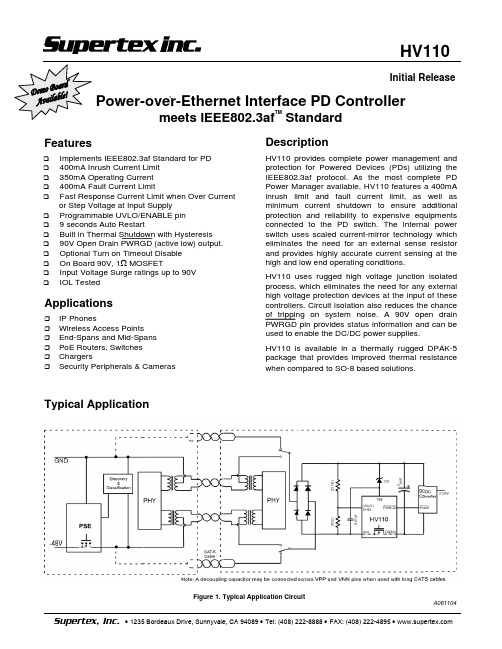
HV110Initial Release Power-over-Ethernet Interface PD Controllermeets IEEE802.3af TM StandardFeaturesImplements IEEE802.3af Standard for PD400mA Inrush Current Limit350mA Operating Current400mA Fault Current LimitFast Response Current Limit when Over Currentor Step Voltage at Input SupplyProgrammable UVLO/ENABLE pin9 seconds Auto RestartBuilt in Thermal Shutdown with Hysteresis90V Open Drain PWRGD (active low) output.Optional Turn on Timeout DisableOn Board 90V, 1ΩMOSFETInput Voltage Surge ratings up to 90VIOL TestedApplicationsIP PhonesWireless Access PointsEnd-Spans and Mid-SpansPoE Routers, SwitchesChargersSecurity Peripherals & CamerasDescriptionHV110 provides complete power management andprotection for Powered Devices (PDs) utilizing theIEEE802.3af protocol. As the most complete PDPower Manager available, HV110 features a 400mAinrush limit and fault current limit, as well asminimum current shutdown to ensure additionalprotection and reliability to expensive equipmentsconnected to the PD switch. The internal powerswitch uses scaled current-mirror technology whicheliminates the need for an external sense resistorand provides highly accurate current sensing at thehigh and low end operating conditions.HV110 uses rugged high voltage junction isolatedprocess, which eliminates the need for any externalhigh voltage protection devices at the input of thesecontrollers. Circuit isolation also reduces the chanceof tripping on system noise. A 90V open drainPWRGD pin provides status information and can beused to enable the DC/DC power supplies.HV110 is available in a thermally rugged DPAK-5package that provides improved thermal resistancewhen compared to SO-8 based solutions. Typical ApplicationFigure 1. Typical Application CircuitA061104Electrical Characteristics (at 0°C < T A< +75°C, unless otherwise specified)Absolute Maximum Ratings*Supply Voltage, V pp(1)-0.5V to 90V Operating Temperature Range -40°C to +85°C Storage Temperature Range-65° to +150°C5-Pin DPAK Thermal Resistance R θJA (minimum footprint) 110°C/WUVLO/Enable Input(1)6VOrdering InformationPackage OptionsDEVICEDPAK-5HV110 HV110K4* Absolute Maximum Ratings are those values beyond which damage to device may occur.Functional operation under these conditions is not implied.Continuous operation of the device at the absolute rating level my affect reliability. All voltages are references to V NN pin.( 1 ): HV110 will work in both Positive and Negative voltage applications, the maximum differential voltage between the V PP and V NN pins must not be exceeded. ( 2 ): UVLO Threshold to be modified using external resistors, when a zener diode is connected to V PP pin. (See Signature Detection) ( 3 ): Shorted-circuit timer starts after POR timer. If V OUT does not charge at least 90% V in before t SC then a shorted-circuit condition exists.( 4 ): Under-current timer starts when I OUT goes below I MIN . If I OUT stays below I MIN longer than t UC then MOSFET is turned off due to under current condition.( 5 ): If the output current is in an overload or shorted load condition then the output immediately goes to current limit and starts the over-current timer. If I OUT does not drop back below I LIMIT before the timer expires then an over current condition exists. The timer is immediately reset when a fault is cleared. ( 6 ): Time for fast return to limit circuit to react.Pin DescriptionV PP – Positive voltage supply inputV NN – Negative voltage power supply inputDRAIN – Internal N-channel MOSFET drain output UV/ENABLE – Under Voltage Lockout Input PWRGD – Active-Low Power Good OutputFigure 3. Package Drawing: DPAK-5Figure 2. HV110 Functional Block DiagramPowered Ethernet RequirementsPower-over-LAN (sometimes called Powered Ethernet or Powered VoIP) is the general concept of providing high voltage (48VDC) power over existing networking cables, such as Ethernet cables. This is accomplished either by using the CAT5 Ethernet Cable’s unused spare pairs or the signal pairs (ENV B vs. ENV A).In Power-over-LAN applications there are two main types of equipment: the Power Sourcing Equipment (PSE) and the Powered Device (PD). There is a third type called Midspan equipment that plugs inline and converts a conventional router into a PSE.The IEEE802.3af standard specifies the requirements, features and characteristics of the PSE and PD devices for use in PoE applications. HV110 is a PD controller IC, capable of handling all the current and timing requirements of the IEEE802.3af standard.A PD designed to this standard and within its range of available power, can obtain both power and data for operation via the standard LAN cables and there-fore will not require any additional power sources or connections.Power-over-Ethernet (PoE) StandardsIEEE802.3af standard, DTE Power via MDI , deals with the specification of the interface that can supply/draw power using the same generic cabling as that used for data transmission. It allows both power and data to flow through the Media Dependent Interface (MDI) (like 10Base-T, 100Base TX or 1000BaseT) to the Data Terminal Equipment (DTE 1) safely and effectively. It defines the functional and electrical characteristics of two optional power (non-data) entities – the Powered Device (PD) and the Power Sourcing Equipment (PSE) that makes this single interface possible. The mechanical and electrical interface between PSE and PD and the transmission line is achieved through the Power Interface (PI) Devices (usually the LAN cables).1(DTE) A device which acts as the source and/or destination of data and which controls the communication channelPSE is defined as a device that provides a single portion of the link (10BASE-T, 100BASE_TX or 1000BASE_T) with both the data it requires and the power to process this data. PSEs may be placed with the DTE/Repeater/Midspan. A PSE that is located along with the DTE/Repeater is called Endpoint PSE, while a PSE that is located within the link, between the MDIs is called a Midspan PSE. All the specifications for the PSE sitting in the End Point (e.g. the router) may not apply for the Midspan PSE. Even though HV110 is a PD device, it is closely associated with the operation of PSE, in fact it is dependent on the PSE for its normal operation. HV110, however, unlike many other PD controllers, provides redundant PSE protections and timings for maximum protection while ensuring compliance. Hence certain basic functionalities of the PSE are included in this data sheet for better understanding some of the features and operation of PDs.HV110 PSE Power StandardsPSE powers a single link. It searches the link for aPD and supplies power to the link only after a PDSignature is detected. The PSE will reject any linkswith an invalid PD Signature. When the PD isremoved, the PSE will also remove the power fromthe link.PSE may be able to do an optional Classification of the PD, to detect the maximum power drawn by the PD, to do some high level Power Management. PSE is limited to a continuous maximum output of 15.4W.DiscoveryKey to all Power-over-Ethernet methods is Discovery. Discovery is the method used to determine if a device at the end of the cable is capable of receiving high voltage DC, before applying high voltage. Discovery also is used for determining when a PD device is disconnected or removed subsequently. The reason for all of this is that high voltages (-48V) connected to many legacy devices can cause equipment damage. For this reason Discovery takes place at voltages compatible with existing legacy equipment and high voltage DC is only applied once discovery is satisfied. The IEEE802.3af Discovery is based upon the sensing of a characteristic impedance. This impedance is defined nominally as 25k (23.5k to 26.25k) with no more than 0.1uF of capacitance in parallel with the impedance, in a voltage range from 2.8V to 10V. The presence of diode rectification at the PD end forces a slope impedance method, requiring at least two operating point measurements, to eliminate the effect of diode level shift.Classification (optional)As per the IEEE802.3af standards, the PSE has to deliver a minimum of 15.4W to a PD connected to it while limited by the 350mA maximum operating current. Not all PD devices, however, require this much power to operate. For example an IP Phone with a monochrome screen will require far less power than an IP Phone with color display. By identifying the power drawn through each port, PSE can assist in the System Power Management protocol to determine the total number of PDs it can support, depending on the output capacity of the system power supply.To achieve this type of power management an optional step was added to the IEEE802.3af standard called ‘Classification’. Classification allows a device to communicate the maximum power it will ever demand to the PSE so that the Power Management Protocol can allocate the unused power to other ports, enabling the full utilization of the installed capacity. Table 1 identifies the different classifications included in the IEEE802.3af standard. In order to identify the class of the PD connected, the PSE sends a second voltage signal of 15 to 20V, slightly higher than signature detection voltage and measures the current. Depending on the magnitude of the current drawn, the PSE will classify the load to one of the four Classes as shown in Table 2, and will assume that the load will not draw any additional power than shown for the given Class.Note that Class 0 default will work for all devices & Classification is only needed in the rare instance when a multi-port switch or router wants to rate the system supply lower than the combined Class 0 port output; a situation which will reduce it’s potential classification base. In fact most of the PD devices, like Wireless Access Points, in the market today are Class 0 devices and hence do not require any classification methods. HV110 therefore does not force the use of resistors and wasted silicon area to implement a Classification current source. HV110, however, can be made to be compatible with classification by utilizing low cost circuitry as shown in Figure 9.DisconnectThe PSE must be able to remove the power from a port once the PD is removed. The purpose of this is to prevent damage to non-compatible devices connected to the same link at a later time. As per the DC disconnect requirements, the PSE may disconnect load if the current is between 5mA and 10mA and must disconnect between 0-5mA, if the condition persists for more than 300ms. Although not required by a PD device, HV110 includes a “minimum circuit breaker” which when the current is in a range less than 20mA will cause a shutdown after the 300ms if the PSE does not react.Class Usage PDPower0 Default0.44–12.95W1 Optional0.44–3.84W2 Optional3.84–6.49W3 Optional6.49–12.95WTable 1. PD Power ClassificationClass ProbeVoltageMin.(mA) Max. (mA)0 15-20V 0.5 41 15-20V 9 122 15-20V 17 203 15-20V 26 30Table 2. Classification Signature measured at PD connectorHV110PD Power StandardsAccording to the IEEE802.3af standards, the PD must operate from 36V to account for a potential 8V line drop across the impedance of the network during inrush (400mA max current x 20Ω line-impedance). The UVLO must allow a 44V max turn-on and a 30V minimum turn off. A PD device may draw a maximum power of 12.95W. The maximum power that can be expected is limited by the 20Ωline resistance carrying the 350mA current to the PD at the minimum input voltage of 44V (power delivered is 12.95W [{44 – (20*0.35)}*0.35].PD ApplicationIEEE Electrical & Timing Requirements Below are of the major features of HV110, some of which are usually found only in PSE devices.Provides an internal current limit for inrush, normal operation and overload conditions.Limits the input current to less than 10µA that will not interfere with Discovery from 2.6V to 10V(with Zener as shown in Figure 1).Meets the turn-on and turn-off thresholds for the PD device & has a built-in 8V hysteresis (with PNP transistor as shown in Figure 10).Protects the device from thermal run away, with thermal shut down and built in 9 sec restart timer.UVLO & POR provides hot-swapping/de-bounce capabilities and inrush current limit.DC/DC converter.Complies with the timing requirements for IEEE 802.3af standard.Classification can be easily implemented, as shown in Figure 9.In addition to operating as a PD controller, HV110 can function as a redundant protective element to assure reliable operation and compliance to IEEE802.3af standard for the PD, even in cases where the PD is powered from an auxiliary power source, as shown in Figure 11.Thermal ShutdownHV110 is designed with a built in Thermal Shutdown feature to assure higher levels of reliability. It will shutdown if the temperature on the die reaches 140°C and will try to restart when the temperature drops to 120°C. Auto RestartAny fault condition will cause the device to shut down and enable a 9 second auto-restart timer. This will occur indefinitely and is strong protection against PSE error when the HV110 is used in PD applications.Note that a 9 second auto-restart will disconnect the PD due to under current conditions, and will also turn off the PSE, since the PSE will not see the minimum current for greater than a period of 400ms (350ms nominal).PWRGDThe PWRGD (active low) pin is an open drain active low MOSFET, (referred to VNN) which is enabled when the gate voltage on the internal power MOSFET reaches its full on voltage, provided that the slew rate (Vslew) timeout for large capacitor is not being used.Any fault condition will return PWRGD to a high impedance state, turning off the HV110 and the DC/DC converter. The PSE will also detect an undercurrent condition for a period greater than 350ms (nominal), and will shut down by itself. It will then wait for the next Discovery cycle.Programmable UVLO and Hysteresis ULVO is internally set through a 2.5Mohm and 116K resistance divider in HV110. The default values of UVLO are given in the Electrical Characteristics on Page 2.The UVLO circuit has a built in Hysteresis of 8V, to enable stable operation during a UV condition. See the section on Signature Detection for further details.Internal MOSFET with Current MirrorHV110 includes an internal 90V, 1ohm MOSFET. The MOSFET current is mirrored to a current detect circuit within the chip, utilizing a proprietary Supertex algorithm and wastes almost no power. Elimination of a sense resistor necessary with external power switches means additional energy savings, providing higher power output. Use of an on-board FET and the thermal supervisor also leads to high reliability compared to ICs that use external FETs whose temperatures cannot be easily monitored.PD PolarityAccording to IEEE802.3af, PD shall be insensitive to the polarity of the power supply and shall be able to operate in Mode A and Mode B (cases when the power is transferred through the signal leads andHV110spare leads). The connections to the 8-pin modulator jack are different for Mode A and Mode B, polarity on the pins can be different for Mode A.Accommodating the different pin combinations and polarity are beyond the scope of the PD Controller IC, however these must be taken care of in the system design. One of the ways of ensuring the polarity protection is to use a small bridge rectifier in between the 8-pin connector terminal and the PD Controller.Description of OperationSignature DetectionDuring the Discovery process, the PSE applies a voltage as described in the Discovery section on Page 4 and determines if there is a PD connected at the other end of the cable. The power loss across the 25K signature resistor will be less than 120mW - less than 1% of the power delivered to PD. It is therefore not critical to disconnect the Signature Resistor after the PD detection. However, this can be easily accomplished by using a low cost bipolar transistor and resistors. Note that the resistance of the external circuit connected between the DRAIN and VPP pin of the HV110 should be greater than 500k Ω (in the 2.8V – 10V Discovery voltage range) for the signature detect to work properly (usually the case with active loads like DC-DC converters). Because of the zener diode connected to V PP pin, it will be necessary to modify the internal UVLO thresholds by using two external resistances as shown in Figures 1, 9 and 11, to provide the UVLO turn-off and turn-on voltages to meet the IEEE 802.3af standard. These two resistors perform dual functions, UVLO voltage adjustments and also the Signature Detection function (i.e. represent the 25k impedance). Figure 10 shows a different implementation using a PNP transistor which allows the use of the HV110’s internal UV circuit.Once the voltage exceeds 12V, the HV110 will turn on and begin drawing a quiescent current of 1mA typical.Current Limit FunctionsHV110 monitors the drain voltage and the current in the load switch. During initial inrush if the drain does not move more than 90% of input voltage within a short-circuit timer period (t SC = 60ms), then the device will conclude that a short circuit condition exists, will turn off the internal FET and try to auto-restart after a period of 9 seconds. If the initial inrush period ends within this period as per the IEEE802.3af standards then the internal FET isturned fully on to minimize its on resistance and the PWRGD pin will be pulled low, to the negative rail. Figure 4 shows the turn on sequence of the HV110. Once Discovery is complete, the PWRGD will be high impedance. After the optional Classification is complete and UVLO is satisfied, HV110 will provide a controlled turn on of the internal switch (90V, 1Ω Power MOSFET), limiting the inrush current maximum value of 350mA (nominal).During regular operation a fault condition can occur.HV110 includes a current monitor that continuously t is not cleared within the nominal Over-current timer limit of 60ms, HV110 will turn off thePWRGDI nput VoltageDRAINInput CurrentFigure 4. Turn-on waveforms of the HV110watches the FET current. If the current exceeds 350mA (nominal), fast-return to limit feature will be activated and the over-current limit circuit will limit the output current to 350mA (nominal), as shown in Figure 5.If the faul nput VoltagePWRGDDRAINInput CurrentFigure 4. PD current jumps from 200mA to 400mA,Controller shuts down in 60msFigure 5. PD Current jumps from 200mA to 400mA, Controller shuts down in 60msHV110pass element, and initiate an auto-restart sequence, with a 9 second interval as shown in Figure 6. In the event the over-current is cleared before the over-current timer has expired, then the over-current timer will be reset and the device will start to function normally.DC DiscCurrentonnectnder-current detection circuit to hen the current falls below the PSE in PoE applications hence e tart up currents for port r the IEEE802.3af HV110 includes an u disconnect the PD w under-current threshold level. HV110 will turn the internal FET OFF if the load current falls below a threshold level of 10mA (nominal) for a period HV110 provides most of the safety and timing determined by the under-current timer (Signature drop-out time, t UC 350ms nominal). In Class 0 applications, this acts as an additional protection to help overcome rapid reinsertion of a legacy or a non-compliant device.requirements of a can be considered as a secondary/redundant stage to comply with the IEEE 802.3af standards for the Powered Device. One motivation for this is that the PSE is an unknown quantity and may not be fully IEEE802.3af compliant in all cases. HV110 will ensure that valuable PD devices are not damaged and that they fulfill the IEEE802.3af compliance.Turning on to a large C portThe PSE is required to limit th s C less than 180µF only, as pe current into 300standard. For higher value of C port , the PD has to limit the current. Figure 8 shows that the HV110 limitingµF as required by the IEEE802.3af specification.DRAINFigure 7. Undercurrent shutdown when current fallsfrom 12mA to 9mATo allow charging of extremely large capacitors, the HV110 includes a feature that will disable the turn on timers, PWRGD and Timeout. This feature is based on the turn on voltage slew rate (Vslew). If Vslew is kept below 4.25V/ms then the timers are disabled and limiting will occur indefinitely until C port is charged. This will also, however, disable PWRGD that is enabled by the same timer. In most cases the capacitor used in PD application is well below 180uF so this feature is not of much significance in a PD application.Figure 6. Auto-restart into a shorted outputnput VoltageInput CurrentDRAINFigu gPWRGDre 7. HV110 turning on to a 300uF Cport, still maintainin the maximum input current of 400mA, does not need any additional current limiting elements in the PDFigure 8. HV110 turning on into a 300uF Cport, still maintaining the maximum input current of 400mA(without any additional components required)Application CircuitsClassification OptionFigure 9 above shows the schematic for a typical classification scheme used with HV110. The PSE identifies the Class of the PD, by measuring the current flowing into R class during the Classification Period.The reference voltage at the base of the bipolar transistor (the zener and resistor) should be chosen to draw much less than 1mA so it does not interfere with Classification levels. The zener temperature coefficient is negative (if chosen below 4V) and the V be temperature coefficient is negative providing a first order temperature compensated reference across R class . The (V z -V be )/R class allows programming of the classification current.Choose R class corresponding to the current level of the PD load, using the formula:R class = (V z -V be ) / (I class - I Q -17.5V / 25k*)where V z is the voltage rating of the Zener diode, V be is the voltage across the b-e junction of the bipolar transistor, I class is the classification Signature current corresponding to the power rating of the PD as shown in Table 2 and I Q Quiescent current of the HV110 (1mA). (* Signature resistance)The above factors take into account the quiescent chip current above the 12V zener voltage as well as the Signature resistors in the mid-range of the Classification probe voltage range. As the current ranges are wide, it is possible to ensure that the Classification current is within the ranges of the Table 2 on Page 4 under all conditions. It is however recommended that a voltage reference be used instead of a zener diode as the voltage reference will maintain the voltage across it over a wide current range.The diode from base to PWRGD turns off classification as soon as PWRGD is pulled low to save power. The zener in series with the HV110 will keep the Classification components from drawing current until after Discovery. Make sure that the diode in series with the base of the bipolar transistor can block the maximum expected differential network voltage.Class R class0 Open 1 191 Ω 2 95.3 Ω 3 63.4 ΩTable 3. R class for different classes of PDFigure 9. Classification Circuit with HV110Alternate Method for Powering HV110The 12V zener diode connected to the V PP pin of the HV110 (shown in Figure 1) is required to block the IC in the Discovery process, so that the quiescent current of the IC does not interfere with the signature resistance detect. However, this zener causes a 12V drop across it causing the HV110 to see only 36V. This makes the internal UV thresholds unusable. By using a PNP transistor, along with a low power zener and resistor instead, the built-in undervoltage thresholds can be utilized.Figure 10 shows the modified circuit. In the Discovery stage, the input voltage is less than 10V. This causes the zener to be reverse biased and hence there is no base current to the PNP transistor. Once the input voltage increases beyond 12V, the zener starts conducting, which provides a base current path for the PNP transistor. The transistor goes into the saturation region, essentially pulling V PP to the rail.Figure 10. Powering HV110 using a PNP transistor instead of a zenerOperation with External Auxiliary Power SupplyThere may be cases, when the PD has to be powered by an external Aux power supply, when the PD does not have a PSE at the other end of the Cat 5 cable. In such cases, the PD can be powered by an external power supply as shown. By connecting the power source, before the HV110 controller, the PD will still operate correctly.The higher voltage rating of HV110, will address any voltage spikes up to 90V without the use of any external Zener diodes for input protection. HV110 with its internal current limit and fault timing features will provide a reliable power source to the PD and will allow the smooth transfer of data between the Data terminal and the Powered Device. It may be necessary to connect a blocking diode to prevent any reverse current from being fed back into the Cable to the remote side.Figure 11. Powering HV110 from an Auxiliary power sourceFor additional information on DC/DC controllers and power supplies for PoE applications, see the following:/pdf/datasheets/HV9606.pdf/pdf/misc/HV9606DB4.pdf1235 Bordeaux Drive, Sunnyvale, CA 94089Note: C ircle (e.g. B ) indicates J E DE C R eference.Dimensions in Inches(Dimensions in Millimeters) Measurement Legend =5-LEAD TO-252 PACKAGE (K4)Doc. #: DSPD-5TO252K4 A051804Note: Circle (e.g. B ) indicates JEDEC Reference.Dimensions in Inches(Dimensions in Millimeters) Measurement Legend =Doc. #: DSPD-5TO252K4 A051804。
迈普交换机常用指令

查看POE状态3026G:1.show power inlineS3026G#show power inlinePower Inline Status: OnPower Available: 185 WPower Used: 0 WPower Remaining: 185 WMin V oltage: 44 VMax V oltage: 57 VPolice: OffLegacy: OffDisconnect: AcMode: SignalHW Version: 30SW Version: 05.0.52. show power inline interface [ethernet <interface-number> | <interface-name>]Switch#show power inline interface ethernet1/1-6Interface Status Oper Power(mW) Max(mW) Current(mA) V olt(V)Priority Class------------ ------- ------ --------- ------- -----------Ethernet1/1 enable off 0 15400 0 0 high 0Ethernet1/2 enable off 0 15400 0 0 low 0Ethernet1/3 enable off 0 15400 0 0 low 0Ethernet1/4 enable off 0 15400 0 0 low 0Ethernet1/5 enable off 0 15400 0 0 low 0Ethernet1/6 enable off 0 15400 0 0 low 03、switch# show power fact-power显示结果描述与分析System Total Power : 150.0 W 系统总功率Total Power Allocated : 0.1 W 当前已使用的功率Available power : 149.9 W 剩余可用的功率2. switch# show power pd-status 0/3Power-Over-Ethernet port 0/3 status information:显示结果描述与分析Powered device current : 4.0mA PD的电流Powered device voltage : 46.8V PD的电压Powered device power : 0.1W PD的功率Powered device temperature :45℃POE端口的温度switch>?enable -- Enable Privileged modeexit -- Exit telnet sessionhelp -- helpshow -- Show running system informationswitch>1. 对特权用户配置命令“show interface ethernet 1”,只要输入“sh in e 1”即可。
MaximMAX5995BIEEE802.3bt兼容PD接口控制器解决方案

Maxim公司的MAX5995A/MAX5995B/MAX5995C是IEEE 802.3bt兼容的集成了91W大功率MOSFET的供电设备接口控制器,主要用在以太网供电系统(PoE).器件提供了PD和检测标识,分类标识和集成的具有起动浪涌电流控制的隔离功率开关,简化的墙适配器接口,多事件分类0-8,100V输入最大指标,睡眠模式和超低功耗睡眠模式,主要用在IEEE 802.3bt供电设备,VOIP电话,IP安全班照相机,无线接入点,小型基站和微型基站,照明和建筑物自动化.本文介绍了MAX5995B主要优势和特性,框图,典型应用电路图以及评估板MAX5995 EVK主要特性,电路图材料清单和PCB设计图.The MAX5995A/MAX5995B/MAX5995C provide a complete interface for a powered device (PD) to comply with the IEEER 802.3af/at/bt standard in a Power-Over-Ethernet(PoE) system. The devices provide the PD with a detection signature, classification signature, and an integrated isolationpower switch with startup inrush current control.During the startup period, the devices limit the current to 135mA (typ) before switching to the higher current limit (1800mA to 2400mA, typ)when the isolation power MOSFET is fully enhanced. The devices featureMulti-Event classification, Intelligent MPS (MAX5995B/MAX5995C),Autoclass (MAX5995C), an input UVLO with wide hysteresis and longdeglitch time to compensate for twistedpair cable resistive drop and toassure glitch-free transition during power-on/-off conditions. The devices can withstand a maximum voltage of 100V at the input.The devices support a Multi-Event classification method, as specified inthe IEEE 802.3bt standard, and provide a signal to indicate from Type 1 to Type 4 Power Sourcing Equipment (PSE). The devices can detect thepresence of a wall adapter power source connection and allow a smooth switch-over from the PoE power source to the wall power adapter.The devices also provide a power-good (PG) signal, twostep currentlimit and foldback control, overtemperature protection. A sleep modefeature in the MAX5995A/MAX5995B minimizes low power consumption while generating the Maintain Power Signature (MPS) to maintain PSEconnection. An Ultra-Low-Power sleep mode feature in theMAX5995A/MAX5995B further reduces power consumption while stillgenerating MPS current. The MAX5995B/MAX5995C provides Intelligent Maintain Power Signature (IMPS) feature to automatically enable MPScurrent by detecting the port current.The devices feature a LED driver that is activated during sleep mode, Ultra-Low-Power sleepmode(MAX5995A/MAX5995B), and Intelligent MPSmode(MAX5995B/MAX5995C). Multi-Event indication feature providespatterned signals to indicate power level allocated from PSE to PD in 5different scenarios.The MAX5995C provides Autoclass feature to enable advancedapplications that allow the PSE to effectively optimize power allocation to PD.Maxim MAX5995B IEEE 802.3bt兼容PD接口控制器解决方案The MAX5995A/MAX5995B/MAX5995C are available in a 16-pin, 5mm x 5mm, TQFN power package. These devices are rated over the -40oC to +85oC temperature range.MAX5995B 主要优势和特性:● IEEE 802.3af/at/bt Compliant● Type 1~4 PSE Classification Indicator or an External Wall Adapter Indicator Output● Simplified Wall Adapter Interface ● Multi-Event Classification 0–8● Intelligent MPS (MAX5995B/MAX5995C, Patent US9152161)● Sleep Mode and Ultra-Low-Power Sleep Mode (MAX5995A/MAX5995B)● 100V Input Absolute Maximum Rating ● Inrush Current Limit During Startup ● Current Limit During Normal Operation ● Current Foldback Protection ● Undervoltage Lockout at 36V● LED Driver with Programmable LED Current (MAX5995A/MAX5995B)● Overtemperature Protection ● Multi-Event Power Level Indication ● Autoclass Feature (MAX5995C)● Thermally Enhanced, 5mm x 5mm, 16-Pin TQFNMAX5995B 应用:● IEEE 802.3bt Powered Devices ● VOIP Phones, IP Security Cameras ● Wireless Access Point ● Small Cell, Pico Cell ● Lighting● Building Automation图1:MAX5995B 简化框图图2:MAX5995A/B 功能框图图3:MAX5995C 框图图4:MAX5995A/B典型应用电路图图5:MAX5995C典型应用电路图。
千兆网卡设置

千兆网卡设置熟悉无盘或是专业的网维网管都晓得8168/8111c网卡在默认设置下系统运行过程中常会有些小问题,现在我们将近这种网卡的最佳设置告诉大家,设置如下:在网卡高级选项中把一些选择按照本文的要求设置即可达到8168/8111c网卡的最佳效果802.1Q/1P VLAN Tagging (802.1/1P 虚拟网路标签)改成关闭Flow Control (流量控)改成关闭Jumbo Frame (巨帧)改成关闭Offload Checksum (硬件效和)改成关闭Offload TCP_LargeSemnd 改成关闭1.双击右下角的两个小电视(上网就一闪闪的那个),也可以右键点网上邻居点属性再双击本地连接2.点属性3.点配置在电源管理中:允许计算机关闭这个设备以节约电源关掉!在高级里面:不同网卡如下先说几个比较关键的:1,Flow Control =流量控制网卡默认设置网卡自动限制你的网络流量,比如说平时很流畅,打海山,一A怪就掉线,为什么?流量大。
2,Checksum Offload 数据包校验网卡默认设置网卡的自动校验而导致一旦有一点问题,后续的包便全部不处理而出现假掉线,而服务器忙得话,出错的几率就大3,大量传送减负网卡默认设置大量传送减负是用网卡硬件分割TCP数据包,但其实只有关闭它才可以发挥网卡的真正性能,cpu占用率会提升,但不明显。
网络处理速度会快一些。
NF网卡高级设置Checksum Offload 数据包校验建议关闭Flow Control 流量控制一定要关闭IEEE802.1P Support IEEE802.1P支持建议关闭Jumbo Frame Payload Size 默认是1500 这个是千兆网络一个新的设置,在下文详细叙述。
Low Power State Link Speed 网卡节能建议关闭Network Address MAC的修改默认为不存在一般不必改动Optimize For CPU/Throughput为CPU占用优化或为吞吐量进行优化,设置为CPU的话,网卡的速度被限制,但CPU占用会很低,假如改为Throughput的话,网卡的性能才能完全发挥,但CPU的占用也会上升不少。
奥迪尔XFG1 HD IP固定光学摄像头技术说明书

XFG1 HD IPFixed Optical CameraDisclaimer of warranties and limitation of liabilityThe information, recommendations, descriptions and safety notations in this document are based on Eaton Corporation’s (“Eaton”) experience and judgment and may not cover all contingencies. If further information is required, an Eaton salesoffice should be consulted. Sale of the product shown in this literature is subject to the terms and conditions outlined in appropriate Eaton selling policies or other contractual agreement between Eaton and the purchaser.THERE ARE NO UNDERSTANDINGS, AGREEMENTS, WARRANTIES, EXPRESSED OR IMPLIED, INCLUDING WARRANTIES OF FITNESS FOR A PARTICULAR PURPOSE OR MERCHANTABILITY, OTHER THAN THOSE SPECIFICALL Y SET OUT IN ANY EXISTING CONTRACT BETWEEN THE PARTIES. ANY SUCH CONTRACT STATES THE ENTIRE OBLIGATION OF EATON. THE CONTENTS OF THIS DOCUMENT SHALL NOT BECOME PART OF OR MODIFY ANY CONTRACT BETWEEN THE PARTIES.In no event will Eaton be responsible to the purchaser or user in contract, in tort (including negligence), strict liability or other-wise for any special, indirect, incidental or consequential damage or loss whatsoever, including but not limited to damage or loss of use of equipment, plant or power system, cost of capital, loss of power, additional expenses in the use of existing power facilities, or claims against the purchaser or user by its customers resulting from the use of the information, recommendations and descriptions contained herein. The information contained in this manual is subject to change without notice.2XFG1 HD IP OPtIcal FIXeD camera TMOX001.A September 2021 Table of Contents1.0 INTRODUCTION (4)2.0 GENERAL SAFETY MESSAGES AND WARNINGS . . . . . . . . . . . . . . . . . . . . . . . . . . . . . . . . . . . . . . . . . . .43.0 GENERAL ARRANGEMENT (5)4.0 ELECTRICAL INSTALLATION (6)5.0 CERTIFICATION / LABELLING & MARKING (7)6.0 INSTALLATION (7)7.0 MAINTENANCE (8)8.0 INSPECTON SUMMARY (8)A EX ANNEX – CONTROLLED ATEX DOCUMENT (9)3XFG1 HD IP OPtIcal FIXeD camera TMOX001.A September 2021 4XFG1 HD IP Fixed Optical Camera StationXFG1 HD IP OPtIcal FIXeD camera TMOX001.A September 2021 1.0 INTRODUCTIONThis camera, intended for use in potentially explosive gas and dust atmospheres, is available in versions suitable for use in the following gas/dust groups: IIB IIIC.The Ex enclosure is manufactured from a UV stable glass reinforced polyester with a rugged thermoplastic Sunshield. GRP and 316 Stainless Steel mounting brackets, cover screws and fixings are incorporated throughout thus ensuring a corrosion free product.An uncertified version is available for use in non-explosive atmospheres.2.0 GENERAL SAFETY MESSAGES AND WARNINGSAll instructions and safety messages in this manual must be followed to allow safe installation of the device. The device must only be installed and maintained by correctly trained site personnel/installers. See also certified annex for special conditions for safe use.i. To reduce the risk of ignition of hazardous atmospheres and shock, do not apply power to the device until installation has been completed and the device is fully sealed and secured.ii. To reduce the risk of ignition of hazardous atmospheres and shock, keep device tightly closed when the circuit is energised.iii. Before removing the cover for installation ormaintenance, ensure that the power to the device is isolated.iv. Following installation, test the device to ensure correct operation.v. Following installation ensure a copy of this manual is made available to all operating personnelvi. When installing the device, requirements for selection,installation and operation should be referred to e.g. IEE Wiring Regulations and the ‘National Electrical Code’ inNorth America. Additional national and/or local requirements may also apply.vii. Cable termination should be in accordance with the specification applying to the required application. MEDC recommends that all cables and cores should be correctly identified. Please refer to the wiring diagram in this manual (or separate diagram provided with the unit).viii. Ensure that only the correct listed or certified cable glands are used and that the assembly is correctly earthed.ix. Ensure that only the correct listed or certified stopping plugs are used to blank off unused gland entry points inaccordance with EN/IEC60079-14 clauses 16.3, 16.4 & 16.5 and that the NEMA/IP rating of the unit is maintained. x. MEDC recommend the use of a sealing compound such as HYLOMAR PL32 on the threads of all glands and stopping plugs and/or a suitable sealing washer in order to maintain the IP rating of the unit.xi. The internal earth terminal must be used for protective earthing when required. Do not remove the internal ground strap from the earth terminal where fitted.xii. For units with metric entries; gland continuity and earthing may be achieved with an optional externalearth plate. If the external plate is fitted, a thread sealing compound such as HYLOMAR PL32 must be employed to maintain the IP rating of the unit.xiii. When installing the device, MEDC recommends the use of stainless-steel fasteners. Ensure that all nuts, bolts and fixings are secure.xiv. The unit should never be positioned with the sunshield horizontal facing down.xv. The purchaser should make the manufacturer aware of any external effects or Aggressive substances that the equipment may be exposed to.5XFG1 HD IP Fixed Optical Camera StationXFG1 HD IP OPtIcal FIXeD cameraTMOX001.A September 2021 Fig.1 Tilt / Swivel bracket3.0 GENERAL ARRANGEMENT6XFG1 HD IP Fixed Optical Camera StationXFG1 HD IP OPtIcal FIXeD camera TMOX001.A September 2021 Fig.2Wall mounting bracketThe XFG1 is supplied with a tilt-swivel bracket (fig.1), which is fitted as standard to the camera. Also, the wall mounting bracket, (fig.2) supplied separately in the packaging, is to be installed in the desired location before attaching the XFG1 & tilt-swivel assembly.4.0 ELECTRICAL INSTALLATIONElectrical installation and servicing should only be carried out by qualified service personnel and in accordance with all local/national codes of practice and standards e.g. EN 60079- 14:2014 and IEC 60079-14:2013.Due to the large number of possible configurations, this manual only covers the standard installation of the units.For detailed connection and configuration of units, the installer should refer to individual project specific drawings and information.Units can be supplied, as required, with either AC or DC 24V, or 220VAC Supply; all ±10% The units should only be powered from the specified voltage, no allowance is made for varying voltage supply. Units may also work with Power Over Ethernet (POE) 12V,24v,48v & 56V DCWarning: irreparable damage to the unit will result from an incorrect power supply voltageFor safe access to electrical connections with the camera, refer to ATEX controlled certified ANNEX to this manual.7XFG1 HD IP Fixed Optical Camera StationXFG1 HD IP OPtIcal FIXeD camera TMOX001.A September 2021 5.0 CERTIFICATION / LABELLING & MARKINGThe certifi cation & rating labels are etched on 316 stainless steel and fi xed to the units using stainless steel rivets. The contents of the label will be in ENGLISH. The label shows:A - Name of ManufacturerB – Model TypeC - Operating VoltageD - EX ratings,E - ATEX Certifi cate & IECEX certifi cate numbersF - Serial Number,G - Notifi ed Body NumberATEX/IECEx Enclosure Label CODING IECEx & ATEXII 2 G Ex db *IIB *T4 Gb -##°C ≤ Ta ≤ +##°C II 2 D Ex tb IIIC T135°C Db IP66/67*=T class, Gas GroupNote: T class, is dependent on the maximum specifi edoperating temperature## = Ambient Temperature range. Marked Ambient rangecan be any of the following: -55°C to +40°C, -55°C to +55°C,-55°C to +85°C6.0 INSTALLATIONIt is not anticipated that entry into the fl ame proof enclosure will be required by the user as power and transmission cables are supplied pre-installed with the unit. However, when opening the unit for any reason, follow the steps below.WARNING: DO NOT OPEN WHEN ENERGISED OR WHEN ANEXPLOSIVE ATMOSPHERE IS PRESENT. CLEAN WITH DAMP CLOTH1. Cable termination should be in accordance with specifi cations applying to the application.2. MEDC recommend that all cables and cores should be fully identifi ed.3. Ensure that only the correct certifi ed glands are used, and that the assembly is shrouded and correctly earthed4. Ensure there is not too much slack of cable cores within the unit, due to space limitations.5. Ensure that only the correct certifi ed stopping plugs are used to blank any unused gland entry points. We recommend the use of ‘HYLOMAR PL32 COMPOUND’ on the threads of stopping plugs in order to maintain the IP66/67 rating of the unit.6. Unscrew the grub screw on the Lens cover assembly one full turn (2.0mm A/F hexagon key required).7. Unscrew and remove the cover. Once the cover has been removed, slide the camera from the enclosure.8. To replace the cover, use the same procedure as above but in reverse manner, ensuring the cover is screwed tightly. There should be a maximum gap of 0.2mm between the faces of the enclosure and cover to ensure 0-ring compression.8XFG1 HD IP Fixed Optical Camera StationXFG1 HD IP OPtIcal FIXeD camera TMOX001.A September 2021 Warning: this cover must not be removed underany circumstances, until at least 5 minutes after the power source is disconnected.Fig.3 Gaining access to the T erminalsSlide the camera from the enclosure.See Note 7.Loosen the grub screw before attempting to unscrewthe cover.See Note 6.7.0 MAINTENANCEDue to the rugged construction of the unit, little or no maintenance should be required during the working life of the unit. GRP will resist attack by most acids, alkalis and chemicals and is as resistant to concentrated acids and alkalis as most metal products.However, if abnormal and/or persistent unusualenvironment conditions occur due to plant damage or accident etc, then a visual inspection is recommended.If the unit requires cleaning, then only clean with a damp cloth to avoid electro-static charge build up.Recommended inspection interval: 6 Months to ensure trouble free operation and extended product life. It is recommended that, where the unit is exposed to regularly extreme weather conditions, the ‘O’ ring weather seal in the removable window is replaced every fi ve years. If the cover/lens assembly grease needs to be re-applied, a PFPE (Perfl uoropolyether) based grease such as Krytox GPL203 by DuPont or Perfl uorolube 22/6 by Performance Fluids Ltd should be used, to prevent damage to the O-ring.Fixings and fastenings should be checked for tightness and integrity as part of the 6 monthly inspectionintervals. All cable entries and cables should be checked for integrity at these points also.Extreme and harsh environments may require morefrequent inspection and maintenance checks. Therefore, the end user or installer shall ensure that this equipment is protected against external infl uences which could adversely affect the explosion protection or contact the manufacturer if in doubt of the suitability of this equipment in the environment in which it is to be installed.8.0 INSPECTON SUMMARYAt every Inspection interval, carry out the following:• Clean the exterior of the unit.• Check the ‘O’ ring weather seals and replace if necessary.• Check the integrity of all cable entries and cables.• Check condition & tightness o all fasteners on the unit and any mounting points.• Use only Eaton approved spare parts.9XFG1 HD IP Fixed Optical Camera StationXFG1 HD IP OPtIcal FIXeD camera TMOX001.A September 2021 A Ex ANNEX – Controlled ATEX DocumentTitle:Series XFG1 flame proof cameras. Installation & Maintenance InstructionsDocument:XFG1 CAMERARevision: 1.0Date: 29/04/2021This is a certified Annex and must not be changed without authorization SPECIFIC CONDITIONS FOR SAFE USE1. No modification must be made to the flame paths of the unit without consultation to the drawings listed on the schedule.2. Cable Temperature rise at the branching point may be 30K, suitably rated cable must be used.3. When fitted, the optical fibre output from the camera must always be terminated within a suitably certified enclosure or safe area.4. Only armoured cable or conduit is to be utilized when fitted with a fibre optic output in order to protect the fibre optic cable.5. Precautions must be taken to avoid dust from forming layers on the equipment.6. Painting and surface finishes, other than those applied by the manufacturer, are not permitted.7. Cable entry holes are provided as specified on the certified drawings for the accommodation of flameproof cable entry devices, with or without the interposition of a flameproof thread adapter. Unused entries are to be fitted with certified flameproof stopping plugs. The cable entry devices, thread adapters and stopping plugs shall be suitable for the equipment, the cable and the conditions of use and shall be certified as Ex Equipment and not an Ex Component. When used in an explosive dust atmosphere the cable entry devices shall maintain the ingress protection of the enclosure.8. When an adapter is used with an increased safety, dust protected, or a flameproof enclosure for which an IP rating is specified, the interface between the enclosure and the adapter and that between the adapter and the cable entry device shall be suitably sealed in accordance with IEC 60079-14 so as to maintain the ingress protection rating of the enclosure9. To prevent the build-up of Electrostatic charge the unit should only be cleaned with a damp cloth.10. The Sunshield is an integral part of the unit containing the certification label and must not be removed.EatonUnit B Sutton Parkway Oddicroft Lane Sutton in Ashfield NottinghamNG17 5FB, UKTelefone : +44 (0) 1623 444 445 email : *******************© 2021 EatonAll Rights ReservedPrinted in UKPublication No. TMOX001.ASeptember 2021Eaton is a registered trademark.All other trademarks are propertyof their respective owners.Changes to the products, to the information contained in thisdocument, and to prices are reserved; so are errors and omissions.Only order confirmations and technical documentation by Eaton isbinding. Photos and pictures also do not warrant a specific layout orfunctionality. Their use in whatever form is subject to prior approvalby Eaton. The same applies to Trademarks (especially Eaton, Moeller,and Cutler-Hammer). The Terms and Conditions of Eaton apply, asreferenced on Eaton Internet pages and Eaton order confirmations.。
DPtech LSW SI系列以太网交换机典型配置手册v
DPtech LSW3600-SI系列以太网交换机典型配置手册手册版本:v1.4软件版本:LSW3600-S221S002D013DPtech LSW3600-SI系列以太网交换机典型配置手册v1.4.docx声明Copyright © 2008-2016杭州迪普科技有限公司版权所有,保留一切权利。
非经本公司书面许可,任何单位和个人不得擅自摘抄、复制本书内容的部分或全部,并不得以任何形式传播。
为杭州迪普科技有限公司的商标。
对于本手册中出现的其他所有商标或注册商标,由各自的所有人拥有。
由于产品版本升级或其他原因,本手册内容有可能变更。
杭州迪普科技有限公司保留在没有任何通知或者提示的情况下对本手册的内容进行修改的权利。
本手册仅作为使用指导,杭州迪普科技有限公司尽全力在本手册中提供准确的信息,但是杭州迪普科技有限公司并不确保手册内容完全没有错误,本手册中的所有陈述、信息和建议也不构成任何明示或暗示的担保杭州迪普科技有限公司地址:杭州市滨江区通和路68号中财大厦6层邮编:310051网址:邮箱:support@7x24小时技术服务热线:400-6100-59约定图形界面格式约定各类标志约定表示操作中必须注意的信息,如果忽视这类信息,可能导致数据丢失、功能失效、设备损坏或不可预知的结果。
表示对操作内容的描述进行强调和补充。
目录1典型配置案例支持的设备型号 (1)2常用维护命令行介绍 (1)2.1登陆设备 (1)2.1.1 SSH方式登陆 (1)2.1.2 Telnet方式登陆 (1)2.2查看设备信息 (2)2.3软件版本升级 (2)2.3.1 Conboot模式下操作 (2)2.3.2命令行下操作 (9)2.4清除配置 (9)3基本二三层转发配置案例 (9)3.1二层转发简介 (9)3.1.1配置需求 (10)3.1.2网络拓扑 (10)3.1.3配置流程 (10)3.1.4配置步骤 (10)3.2三层转发简介 (11)3.2.1配置需求 (11)3.2.2网络拓扑 (11)3.2.3配置流程 (11)3.2.4配置步骤 (12)4端口聚合典型配置案例 (13)4.1端口聚合简介 (13)4.1.1基本概念 (13)4.1.2聚合模式 (14)4.1.3负载分担类型 (14)4.2端口聚合配置案例 (14)4.2.1配置需求 (14)4.2.2网络拓扑 (15)4.2.3配置流程 (15)4.2.4配置步骤 (15)5端口镜像典型配置案例 (17)5.1端口镜像简介 (17)5.1.1端口镜像基本概念 (17)5.1.2端口镜像分类 (18)5.2本地端口镜像配置案例 (18)5.2.1配置需求 (18)5.2.2网络拓扑 (19)5.2.3配置流程 (19)5.2.4配置步骤 (19)5.3远程端口镜像配置案例 (21)5.3.1配置需求 (21)5.3.2网络拓扑 (21)5.3.3配置流程 (21)5.3.4配置步骤 (22)6端口限速典型配置案例 (23)6.1端口限速简介 (23)6.2配置案例 (23)6.2.1配置需求 (23)6.2.2网络拓扑 (24)6.2.3配置流程 (24)6.2.4配置步骤 (24)7端口隔离典型配置案例 (25)7.1端口隔离简介 (25)7.2配置案例 (25)7.2.1配置需求 (25)7.2.2网络拓扑 (26)7.2.3配置流程 (26)7.2.4配置步骤 (26)8 ARP防护典型配置案例 (27)8.1 ARP防护简介 (27)8.1.1 ARP报文有效性检查 (27)8.1.2 ARP用户合法性检查 (27)8.1.3 ARP网关保护 (28)8.2 ARP报文一致性检测配置案例 (28)8.2.1配置需求 (28)8.2.2网络拓扑 (29)8.2.3配置流程 (29)8.2.4配置步骤 (29)8.3 ARP用户合法性配置案例 (30)8.3.1配置需求 (30)8.3.2网络拓扑 (30)8.3.3配置流程 (30)8.3.4配置步骤 (31)8.4 ARP网关保护配置案例 (32)8.4.1配置需求 (32)8.4.2网络拓扑 (32)8.4.3配置流程 (32)8.4.4配置步骤 (33)9路由协议典型配置案例 (34)9.1路由协议简介 (34)9.1.1静态路由协议简介 (34)9.1.2 RIP路由协议简介 (34)9.1.3 OSPF路由协议简介 (34)9.2静态路由配置案例 (35)9.2.1配置需求 (35)9.2.2网络拓扑 (35)9.2.3配置流程 (35)9.2.4配置步骤 (35)9.3 RIP路由配置案例 (37)9.3.1配置需求 (37)9.3.2网络拓扑 (38)9.3.3配置流程 (38)9.3.4配置步骤 (38)9.4 OSPF典型配置案例 (41)9.4.1配置需求 (41)9.4.2网络拓扑 (42)9.4.3配置流程 (42)9.4.4配置步骤 (42)10 DHCP典型配置案例 (45)10.1 DHCP简介 (45)10.2 DHCP Server配置案例 (46)10.2.1配置需求 (46)10.2.2网络拓扑 (47)10.2.3配置流程 (47)10.2.4配置步骤 (47)10.3 DHCP Snooping配置案例 (48)10.3.1配置需求 (48)10.3.2网络拓扑 (49)10.3.3配置流程 (49)10.3.4配置步骤 (50)10.4 DHCP 中继配置案例 (51)10.4.1配置需求 (51)10.4.2网络拓扑 (51)10.4.3配置流程 (52)10.4.4配置步骤 (52)11 QoS典型配置案例 (53)11.1 QoS简介 (53)11.2配置案例 (54)11.2.1配置需求 (54)11.2.2网络拓扑 (55)11.2.3配置流程 (55)11.2.4配置步骤 (55)12 802.1x典型配置案例 (56)12.1 802.1x简介 (56)12.1.1基本概念 (56)12.1.2认证方式 (56)12.1.3端口接入控制模式 (57)12.1.4 Radius认证分类 (57)12.2 802.1x本地认证配置案例 (57)12.2.1配置需求 (57)12.2.2网络拓扑 (58)12.2.3配置流程 (58)12.2.4配置步骤 (58)12.3 802.1x Radius认证配置案例 (59)12.3.1配置需求 (59)12.3.2网络拓扑 (59)12.3.3配置流程 (59)12.3.4配置步骤 (59)13生成树典型配置案例 (60)13.1生成树简介 (60)13.2 STP配置案例 (62)13.2.1配置需求 (62)13.2.2网络拓扑 (63)13.2.3配置流程 (63)13.2.4配置步骤 (63)13.3 RSTP配置案例 (65)13.3.1配置需求 (65)13.3.2网络拓扑 (66)13.3.3配置流程 (66)13.3.4配置步骤 (66)13.4 MSTP配置案例 (67)13.4.1配置需求 (67)13.4.2网络拓扑 (68)13.4.3配置流程 (68)13.4.4配置步骤 (69)14 SNMP典型配置 (72)14.1 SNMP简介 (72)14.2 SNMP配置案例 (73)14.2.1配置需求 (73)14.2.2网络拓扑 (73)14.2.3配置流程 (73)14.2.4配置步骤 (74)15 NTP配置案例 (74)15.1 NTP简介 (74)15.2 NTP配置案例 (75)15.2.1配置需求 (75)15.2.2网络拓扑 (75)15.2.3配置流程 (75)15.2.4配置步骤 (75)16日志收集配置案例 (76)16.1日志简介 (76)16.2日志收集案例 (76)16.2.1配置需求 (76)16.2.2网络拓扑 (76)16.2.3配置流程 (77)16.2.4配置步骤 (77)1典型配置案例支持的设备型号LSW3600-SI系列2常用维护命令行介绍2.1登陆设备2.1.1SSH方式登陆在交换机上开启SSH后,就可以在串口终端上输入设备的管理地址、用户名(初始用户名admin)和密码(初始密码admin_default)登录设备。
8口POE交换机用户说明

D-LinkDES-1008P8-Port 10/100Mbps with 4 PoE Ports SwitchUser GuideFCC WarningThis equipment has been tested and found to comply with the regulations for a Class B digital device, pursuant to Part 15 of the FCC Rules. These limits are designed to provide reasonable protection against harmful interference when the equipment is operated in a commercial environment. This equipment generates, uses, and can radiate radio frequency energy and, if not installed and used in accordance with this user guide, may cause harmful interference to radio communications. Operation of this equipment in a residential area is likely to cause harmful interference, in which case the user will be required to correct the interference at his/her own expense.CE Mark WarningThis is a Class B product. In a domestic environment, this product may cause radio interference, in which case the user may be required to take adequate measures.UL Warninga) Elevated Operating Ambient Temperature- If installed in a closed or multi-unit rack assembly, the operating ambient temperature of the rack environment may be greater than room ambient. Therefore, consideration should be given to installing the equipment in an environment compatible with the manufacturer's maximum rated ambient temperature (Tmra).b) Reduced Air Flow- Installation of the equipment in a rack should be such that the amount of air flow required for safe operation of the equipment is not compromised.c) Mechanical Loading- mounting of the equipment in the rack should be such that a hazardous condition is not achieved due to uneven mechanical loading.d) Circuit Overloading- Consideration should be given to the connection of the equipment to the supply circuit and the effect that overloading of circuits might have on over current protection and supply wiring. Appropriate consideration of equipment nameplate ratings should be used when addressing this concern.e) Reliable Earthing- Reliable earthing of rack-mounted equipment should be maintained. Particular attention should be given to supply connections other than direct connections to the branch circuit (e.g., use of power strips).Ver. 1.00TABLE OF CONTENTSAbout This Guide (1)Purpose (1)Terms/Usage (1)Introduction (2)Fast Ethernet Technology (2)Switching Technology (3)Power over Ethernet (PoE) (4)Features (4)Unpacking and Installation (5)Unpacking (5)Installation (5)Connecting Network Cable (6)Identifying External Components (7)Front Panel (7)Rear Panel (7)Understanding LED Indicators (9)System LED (9)POE status LEDs (Port 1 ~ Port 4) (9)Ethernet port status LEDs (Ports 1~8) (10)PoE Rule (10)Technical Specifications (12)ABOUT THIS GUIDECongratulations on your purchase of the D-Link DES-1008P, an 8-Port 10/100Mbps Fast Ethernet Switch with 4-Port PoE. This Switch integrates 100Mbps Fast Ethernet and 10Mbps Ethernet network capabilities in a highly flexible package. Port-1 to Port-4 on the switch support Power over Ethernet (PoE), meaning it will automatically detect the presence of an IEEE 802.3af-compliant powered device (PD) and provide power through the port. The switch provides up to 15.4 W per PoE port and can be used to power WLAN access points, IP phones, video cameras, and other PD devices. The Switch will automatically detect the network appliance’s requirements, and will supply the required power to each appliance accordingly.PurposeThis guide discusses how to install your 8-Port 10/100Mbps Fast Ethernet Switch with 4-Port PoE.Terms/UsageIn this guide, the term “Switch” (first letter upper case) refers to your 8-Port 10/100Mbps Fast Ethernet Switch with 4-Port PoE and “switch” (first letter lower case) refers to other Ethernet switches.INTRODUCTIONThis chapter describes the features of the D-Link DES-1008P Fast Ethernet PoE Switch and some background information about Ethernet/Fast Ethernet, Switching and Power over Ethernet technology.Fast Ethernet TechnologyThe growing importance of LANs and the increasing complexity of desktop computing applications are fueling the need for high performance networks. A number of high-speed LAN technologies have been proposed to provide greater bandwidth and improve client/server response times. Among them, 100BASE-TX (Fast Ethernet) provides a non-disruptive, smooth evolution from the current 10BASE-T technology.100Mbps Fast Ethernet is a standard specified by the IEEE 802.3 LAN committee. It is an extension of the 10Mbps Ethernet standard with the ability to transmit and receive data at 100Mbps, while maintaining the CSMA/CD Ethernet protocol. Since the 100Mbps Fast Ethernet is compatible with all other 10Mbps Ethernet environments, it provides a straightforward upgrade and takes advantage of the existing investment in hardware, software, and personnel training.Switching TechnologyAnother approach to pushing beyond the limits of Ethernet technology is the development of switching technology. A switch bridges Ethernet packets at the MAC address level of the Ethernet protocol transmitting among connected Ethernet or Fast Ethernet LAN segments.Switching is a cost-effective way of increasing the total network capacity available to users on a local area network. A switch increases capacity and decreases network loading by dividing a local area network into different segments, which don’t compete with each other for network transmission capacity.The switch acts as a high-speed selective bridge between the individual segments. The switch, without interfering with any other segments, automatically forwards traffic that needs to go from one segment to another. By doing this the total network capacity is multiplied, while still maintaining the same network cabling and adapter cards.Switching LAN technology is a marked improvement over the previous generation of network bridges, which were characterized by higher latencies. Routers have also been used to segment local area networks, but the cost of a router, the setup and maintenance required make routers relatively impractical. Today switches are an ideal solution to most kinds of local area network congestion problems.Power over Ethernet (PoE)Power over Ethernet (PoE) integrates power and data onto one single cabling infrastructure, eliminating the need to have AC power available at all locations.Power and Data is integrated onto the same cable, supporting category 5/5e up to 100 Meters. PoE will provide power to PoE compatible devices, such as IP telephones, wireless LAN access points and IP security cameras.PoE is already widely adopted in the market, saving up to 50% of overall installation costs by eliminating the need to install separate electrical wiring and power outlets.Features8 ×10/100Mbps Auto-negotiation Fast Ethernet RJ45 ports with4-port PoE function (port-1 ~ port-4)Compliant with 802.3af specificationSupports PoE power up to 15.4W for PoE portSupports PoE power up to 56W for all PoE portsSupports PoE IEEE802.3af compliant Powered Device (PD)Each port supports auto MDI/MDIX, so there is no need to use cross-over cables or an up-link portFull/half duplex transfer mode for each portWire speed reception and transmissionUp to 1K unicast addresses entities per device, self-learning, and table aging96KBytes packet bufferSupports IEEE 802.3x flow control for full-duplex mode portsSupports Back-pressure flow control for half-duplex mode portsUNPACKING AND INSTALLATIONThis chapter provides unpacking and installation information for the Switch.UnpackingOpen the shipping cartons of the Switch and carefully unpack its contents. The carton should contain the following items:One DES-1008POne AC power adapterFour rubber feetCD-ROM with Product DocumentQuick Installation Guide.If any item is found missing or damaged, please contact your local reseller for replacement.InstallationThe setup of the Switch can be performed using the following steps:The surface must support at least 1.5 Kg (3.5 lbs) for the Switch. The power outlet should be within 1.82 meters (6 feet) of the Switch.Visually inspect the DC power jack and make sure that it is fully secured to the power adapter.Make sure that there is proper heat dissipation from and adequate ventilation around the Switch. Do not place heavyobjects on the Switch.Connecting Network CableThe Switch support 8 10/100Mbps Ethernet ports and Port 1 ~ port 4 are PoE Enabled ports, these PoE port will automatically activate when a compatible terminal is identified. The Switch will supply power through the Ethernet port to the connected PoE powered device (PD).For legacy devices that are not compatible, the PoE port will not offer power to this device. This feature allows users to freely and safely mix legacy and Power over LAN compatible devices on their network. The Switch supports 10Mbps Ethernet or 100Mbps Fast Ethernet and it runs both in half and full duplex mode using two pair of Category 5 cable.These RJ45 ports are Auto-MDI type port. The Switch can auto negotiate to MDI-II or MDI-X type, so you can connect any RJ-45 cable regardless if it is a standard or crossover cable.IDENTIFYING EXTERNAL COMPONENTSThis chapter describes the front panel, rear panel, and LED indicators of the Switch.Front PanelThe figure below shows the front panels of the Switch.Figure 1. Front panelLED Indicator:Comprehensive LED indicators display the status of the switch and the network (see the LED Indicators chapter below).Rear PanelFigure 2. Rear panelPoE Ports (Port 1~4):These ports are PoE Enabled ports, the PoE port will automatically activate when a compatible terminal is identified. The Switch will supply power through the Ethernet port to the connected PoE device. For legacy devices that are not compatible, the PoE port will not offer the power to this device. This feature allows users to freely and safely mix legacy and Power over LAN compatible devices on their network.These ports support network speeds of either 10Mbps or 100Mbps, and can operate in half- and full- duplex transfer modes. These ports also support automatic MDI/MDIX crossover detection, which gives the Switch true, “plug and play” capabilities. Just connect any network cable between the Switch and the device, and The Switch will automatically detect the settings of the device and adjust itself accordingly.Ethernet Ports (Port 5~8):These ports support network speeds of either 10Mbps or 100Mbps, and can operate in half- and full- duplex transfer modes. These ports also support automatic MDI/MDIX crossover detection, which gives the Switch true, “plug and play” capabilities. Just connect any network cable between the Switch and the device, and The Switch will automatically detect the settings of the device and adjust itself accordingly.DC Power Jack: Power is supplied through an external DC power adapter. Check the technical specification section for information about the DC power input voltage.Since the switch does not include a power switch, plugging its power adapter into a power outlet will immediately power it on.UNDERSTANDING LED INDICATORSThe front panel LEDs provides instant status feedback, and helpsmonitor and troubleshoot when needed.Figure 3. LED indicators of the Switch System LEDPWR: (Power Indicator) On : Power OnOff : Power OffPoE status LEDs (Port 1 ~ Port 4)PoE Status: Green : When the PoE powered device (PD) is connected and the port supplies power successfully.Red : When the PoE port has failed, possibly due to:9 PoE power circuit shortage 9 Power over current: over the power current of PD’sclassification9 Out of PoE voltage of 44 ~ 57 VDC outputOff : No PoE powered device (PD) connected.PoE MAX On : When the power output to PDs has reached or exceeded the maximum power budget. No additional PDs connected will be powered.Off : When the system is using less than 46WBlinking When the system power usage is >=56WEthernet port status LEDs (Ports 1~8)10/100M Link/ACT: 10M : When the 10M LED lights on, the respective port is successfully connected to 10M Ethernet network. Otherwise, when the 10M LED is blinking, the port is transmitting or receiving data on the Ethernetnetwork.100M : When the 100M LED lights on, the respective port is successfullyconnected to 100M Fast Ethernet network. Otherwise, when the 100M LED is blinking, the port is transmitting or receiving data on the FastEthernet network.Off : No link.PoE RulePOE Max: this function will help to protect the POE Switch and to stabilize the power transmitting to the powered device (PD).If the system power usage is >= 46, the POE MAX LED will turn on and the system will not provide power to the additional POE PD. This is done to protect the POE Switch itself and to stabilize the power transmitting to the other POE PDs plugged into the Switch.For example: There are POE PDs connected to the POE Switch and the total power consumption is 48 watts. The system will reserve 8 watts for a buffer and the POE MAX LED will light up. Once there is another POE PD inserted, the system will not provide power to the additional POE PD.Priority: This function will help protect the system when the system power is overloaded. The system will disable the PoE function of lower priority PoE ports to maintain the power to higher priority PoE ports.The total power resource for the system is 56W shared between the 4 POE ports (maximum power for per port is 15.4W). If all POE PDs power consumption is over 56W, the system will automatically arrange the priority of these ports. The lower port number will have the higher priority and the higher port number will have a lower priority (Highest priority: Port 1 > Port 2 > Port 3 > Port 4).For example: In this POE Switch, Port 2 is using 15 watts and Port 3,4 is using 15.4 watts, these two ports are using 45.8 watts total. If there is an additional POE PD inserted to Port 1 with 15.4 watts, the system power resource is over current and the priority function will activate. The priority will be applied to the lowest port number to highest port number, so Port 1,3 will use 15.4 watts, Port 2 will use 15 watts, and the system will cut off the power to Port 4 due to over current.TECHNICAL SPECIFICATIONSGeneralStandards IEEE 802.3 10BASE-T EthernetIEEE 802.3u 100BASE-TX Fast EthernetIEEE 802.3x Full Duplex Flow ControlIEEE 802.3af Power over EthernetProtocol CSMA/CDData Transfer Rate Ethernet: 10Mbps (half duplex), 20Mbps (full-duplex)Fast Ethernet: 100Mbps (half duplex), 200Mbps (full-duplex) Topology StarNetwork Cables 10BASET: 2-pair UTP Cat. 3, 4, 5; up to 100m100BASE-TX: 2-pair UTP Cat. 5; up to 100mNumber of Ports 4 × 10/100Mbps Auto-MDIX RJ45 ports with POE enabled (port 1 ~ port 4)4 × 10/100Mbps Auto-MDIX RJ45 ports (port 5 ~ port 8)PoE Power on RJ-45 Power+: ping 3 & ping 6Power-: ping 1 & ping 2Physical and EnvironmentalDC inputs 48VDC/1.45APower Consumption 6.3 watts. (max. no PD device connected)62.3 watts (max. with 56W PoE Device connected)Temperature Operating: 0° ~ 40° C, Storage: -10° ~ 70° CHumidity Operating: 10% ~ 90%, Storage: 5% ~ 90%Dimensions 171 x 98 x 29 mmEMI: FCC Class B, CE Mark Class BCB(IEC60950)Safety: cUL(UL60950),Performance RAM Buffer: 96K bytes per device Filtering Address Table: 1K entries per devicePacketFiltering/Forwarding Rate: 10Mbps Ethernet: 14,880/pps100Mbps Fast Ethernet: 148,800/ppsMAC Address Learning: Automatic update Transmits Method: Store-and-forward。
POE反向供电配置
POE反向供电配置
瑞斯康达POE反向供电使能开启方法
瑞斯康达POE反向供电ONU在反向供电使能未开启的状态下,ONU直连网线到其他设备业务是不能使用的,且ONU的状态指示灯也不亮,需要开启方向供电使能为enable后,才能在没有供电模块下使用该ONU。
若该ONU在瑞斯康达OLT下,可以通过网管配置,开启使能状态,若该ONU在其他OLT(烽火或中兴)下使用,需要手动配置,开启使能状态,具体方法如下:
1、配置电脑IP地址为192.168.1.2-253任意地址;
2、telnet 192.168.1.254(ONU管理地址);
3、输入用户名和密码:raisecom;
4、输入en进入使能配置模式,密码raisecom;
5、输入config进入到config配置模式;
6、在配置模式下输入:interface eth 1(进入端口1);
7、输入:poe pse-off service enable;
8、quit退出端口1;
9、重复步骤6-8进行操作,对所有的端口都进行使能开启;
10、配置完成后,退出到使能配置模式,输入write保存配置。
配置之前后配置完成后都可以使用show poe information查看端口状态是否enable。
POE配置说明

Please input the file name(*.cfg)(To leave the existing filename
unchanged press the enter key):
Now saving current configuration to the device.
5/REBOOT:- 1 -
Reboot device by command.
[H3C-Ethernet1/0/1]apply poe-profile gao
[H3C-Ethernet1/0/1]quit
[H3C]
[H3C]apply poe-profile gao interface Ethernet 1/0/5 to Ethernet 1/0/8//将POE团体功能应用到某些接口上
Unit1 reset saved-configuration successfully.
<H3C>
<H3C>reboot//将交换机恢复为出厂配置,需要重启设备后才能生效
Start to check configuration with next startup configuration file,
The temperature protection is disabled.
[H3C]
[H3C]int Ethernet 1/0/1//进入某个接口
[H3C-Ethernet1/0/1]poe enable//启用此接口的POE功能
[H3C-Ethernet1/0/1]quit
[H3C]
[H3C]poe-profile gao//设置POE团体功能
以下为交换机的POE设置
DS-3E05xxP-E系列未管理的光纤PoE交换机说明书
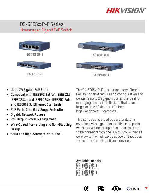
DS-3E05xxP-E SeriesUnmanaged Gigabit PoE Switch• Up to 24 Gigabit PoE Ports• Compliant with IEEE802.3at/af, IEEE802.3, IEEE802.3u, and IEEE802.3x, IEEE802.3ab, and IEEE802.3z Ethernet Standards • PoE Ports Offer 6 kV Surge Protection • Gigabit Network Access•PoE Output Power Management•Wire-Speed Forwarding and Non-Blocking Design• Solid and High-Strength Metal ShellThe DS-3E05xxP-E is an unmanaged Gigabit PoE switch that requires no configuration and contains up to 24 gigabit ports. It is ideal for managing simple installations that have a large volume of video traffic from high-megapixel IP cameras.This series consists of basic standalone switches with gigabit capability on all ports, which allows for multiple PoE field switches to be connected on one DS-3E05xxP-E Series core switch, which saves space and reduces the need to install additional devices.Available models: DS-3E0505P-E DS-3E0510P-E DS-3E0518P-E DS-3E0526P-EDS-3E0505P-E DS-3E0510P-E DS-3E0518P-E DS-3E0526P-ESpecificationsFront PanelDS-3E0505P-E DS-3E0510P-EDS-3E0518P-EDS-3E0526P-ENetwork ParametersPort Number4 x gigabit PoE ports, and 1 x gigabit RJ45 port8 x gigabit PoE ports, 1 x gigabit RJ45 port, and 1 × gigabit SFP fiber optical port 16 x gigabit PoE ports, 1 x gigabit RJ45 port, and 1 x gigabit SFP fiber optical port24 x gigabit PoE ports, 1 x gigabit RJ45 port, and 1 x gigabit SFP fiber optical portPort Type RJ45 port, full duplex, MDI/MDI-X adaptiveStandards IEEE 802.3, IEEE 802.3u, IEEE 802.3x, IEEE 802.3ab, IEEE 802.3z Forwarding Mode Store-and-forward switching Mac Address Table 2K 4K 8K Switching Capacity 10 Gbps 20 Gbps 36 Gbps 56 Gbps Packet Forwarding Rate7.44 Mbps 14.88 Mbps 26.784 Mpps 38.688 MbpsInternal Cache 1 Mbits 1.5 Mbits 4.1 Mbits PoE Power SupplyPoE Standard IEEE 802.3af, IEEE 802.3atPoE Power PinSupport 4-core power supply, and Ethernet cable 1/2/3/6 provide power supply PoE PortPorts 1 to 4 Ports 1 to 8 Ports 1 to 16 Ports 1 to 24 Maximum Port Power 30 W PoE Power Budget60 W 110 W 230 W 370 W Maximum Power Consumption65 W 120 W 250 W 400 WGeneralShell Metal material Weight6.35 lbs (2.88 kg)Dimensions (L x H x D) 17.3" x 1.7" x 8.7" (440 mm x 44 mm x 220.8 mm) Operating Temperature 32° F to 104° F (0° C to 40° C) Storage Temperature -40° F to 185° F (-40° C to 85° C) Operating Humidity 5% to 95% (no condensation) Storage Humidity5% to 95% (no condensation) Power Supply 100 to 240 VAC, maximum 6.5 A Power Consumption400 WDS-3E0510P-EDS-3E0505P-ERearPanelDS-3E0518P-EDS-3E0526P-E DS-3E0510P-E DS-3E0505P-EDS-3E0518P-EDS-3E0526P-E。
Cisco工业以太网3000系列交换机产品简介说明书

Data Sheet Cisco Industrial Ethernet 3000 Layer 2/Layer 3 Series SwitchesProduct overviewThe Cisco® Industrial Ethernet 3000 Series (IE 3000 Series) is a family of Layer 2 and Layer 3 switches that bring Cisco’s leadership in switching to Industrial Ethernet applic ations with Innovative features, robust security, and superior ease of use. The Cisco IE 3000 Series features:●Industrial design and compliance●Tools for easy deployment, management, and replacement●Network security based on open standards●Integration of IT and industrial automation networksThe Cisco IE 3000 Series is an ideal product for Industrial Ethernet applications, including factory automation, energy and process control, and Intelligent Transportation Systems (ITSs).The Cisco IE 3000 offers:●Design for Industrial Ethernet applications, including extended environmental, shock/vibration, and surgeratings; a complete set of power input options; convection cooling; and DIN-rail or 19” rack mounting●Support for Power over Ethernet (PoE) up to 15.4W per port●Support for Power over Ethernet Plus (PoE+) for the PoE+ capable devices up to 30W per port●Easy setup and management using Cisco DNA TM Center software and the Cisco Device Manager webinterface and supporting tools, including Cisco Network Assistant (CNA) and Cisco Prime LMS 4.2●Easy switch replacement using removable memory, allowing the user to replace a switch without having toreconfigure●High availability, guaranteed determinism, and reliable security using Cisco IOS® Software●Recommended software configurations for industrial applications that can be applied at the touch of abutton●Compliance to a wide range of Industrial Ethernet specifications covering industrial automation, ITS,substation, railway, and other markets●Support for IEEE1588v2, a precision timing protocol with nanosecond-level precision for high-performanceapplications●Improved ring resiliency with the support of Resilient Ethernet Protocol (REP)●Transparent IT integration with the support of Layer 3 routing protocols (IP Services)●PROFINET v2 certification, with PROFINET conformance class B compliance●ABB Industrial IT certificationConfigurationsThe Cisco IE 3000 Series software, based on Cisco IOS Software, is a rich suite of intelligent services, supportinghigh availability, Quality of Service (QoS), and security features.The Cisco IE 3000 Series includes the products listed in Table 1.Table 1.Cisco IE 3000 SwitchesCisco IE-3000-4TCCisco IE-3000-4TC-E Cisco IE-3000-8TCCisco IE-3000-8TC-E Cisco IEM-3000-8TM=Cisco IEM-3000-8FM= Cisco PWR-IE50W-AC= Cisco PWR-IE50W-AC-IEC= Cisco IEM-3000-4SM= Cisco IEM-3000-8SM=Cisco IEM-3000-4PC=Cisco IEM-3000-4PC-4TC=Cisco PWR-IE65W-PC-AC=Cisco PWR-IE65W-PC-DC=Industrial Ethernet applicationsThe new Cisco IE 3000 Series is an ideal product for a variety of Industrial Ethernet applications:●Industrial automation: The Cisco IE 3000 is designed to support a wide array of Industrial Ethernetprotocols for automation. The Cisco IE 3000 features a Programmable Logic Controller (PLC) form-factor design with extended environmental ratings, convection cooling, DIN-rail mounting, redundant 24VDCpower input, alarm relays, and surge/noise immunity. The Cisco IE 3000 software and configuration tools allow for easy setup, optimized for Industrial Ethernet applications (for example, EtherNet/IP). Multicast control, traffic prioritization, and security features are specified in default templates recommended for these protocols.●ITS: The Cisco IE 3000 supports ITS and other applications for outdoor video and traffic or transportationsystems control. The switch supports compliance to NEMA TS-2, a variety of gigabit fiber uplinks, and AC and DC power input options, while Cisco IOS Software supports critical ITS features, including virtual LAN (VLAN), QoS, Internet Group Management Protocol (IGMP) snooping, and security Access Control Lists (ACLs).●Substations: The Cisco IE 3000 is fully compliant to substation automation specifications, includingIEC61850 and IEEE1613. The switch supports high-speed ring recovery; fiber access and uplink ports; AC, DC, and a variety of power input options for the substation environments.●Other applications: The Cisco IE 3000 can be deployed in railway, military, Metro Ethernet, and otherapplications requiring unique environmental, form factor, or power inputs in harsh environments.Table 2 gives the features and benefits of the Cisco IE 3000 Series. Table 3 gives the hardware specifications, and Table 4 gives the power specifications. Table 5 gives details on DNA Essentials license support, Table 6 lists supported optics, and Table 7 provides safety and compliance information.Table 2. Features and benefits of Cisco IE 3000 SeriesDesigned for industrial applications ●Extended temperature, vibration, shock and surge, and noise immunity ratings comply to specifications for automation, ITS, and substation environments.●Compact, PLC-style form factor is ideal for deployment in industrial environments.●DIN-rail, wall, and 19” rack mount opt ions allow for deployments in a variety of control systems.●Variety of power input options covers a wide range of power requirements for Industrial Ethernet applications.●Up to 300 deployment configurations, supporting a range of access port densities, copper and fiber uplinks, fiber access ports, and power input, deliver flexibility in deployment.●Support for SFP modules provides uplink connectivity supporting 100BASE-LX, 100BASE-FX, 1000BASE- SX, 1000BASE-LX, and 1000BASE-ZX options.●Alarm relay contacts can be used for an external alert system.Ease of deployment, management, and replacementCisco DNA™Center enables centralized network management with automation and assurance features. Cisco IE 3000 Series supports DNA Essentials subscription licenses with 3- and 5-year term options.https:///c/en/us/products/cloud-systems-management/dna-center/datasheet-listing.html●Cisco Express Setup simplifies initial configuration with a web browser, eliminating the need for more complex terminal emulation programs.●Cisco Smartports templates provide the option to apply a default global or interface-level macro with a recommended configuration, allowing the user to easily set up the switch in a configuration optimized for the specific application.●Smartports templates for EtherNet/IP provide an optimized setup for these Industrial Ethernet protocols at the touch of a button.●Swappable Flash memory is ideal for quick and easy switch replacement. Memory can be moved from one switch to another, so a switch can be replaced without the need to reconfigure software features.●The Cisco IE 3000 can be managed by PROFINET based management tools. The IE 3000 has PROFINET v2 certification, with PROFINET conformance class B compliance.●Simple Network Management Protocol (SNMP) (v1/v2/v3) support allows for management using traditionalIT-based management tools, including CiscoWorks.●Device Manager allows web-based switch configurations.●DHCP port-based allocation retains the IP address on a per port basis and simplifies the end-host replacement in an industrial setting.●HTTPS access●Embedded Event Manager (EEM) provides real-time network event detection and on board automation●Cisco Network Assistant (CNA) is a no-charge, Windows-based application that simplifies the administration of networks of up to 250 users. It supports the Cisco IE 3000 and a wide range of Cisco Catalyst® intelligent switches. With CNA, users can manage Cisco Catalyst switches and launch the device managers of Cisco integrated services routers and Cisco Aironet® WLAN access points. Configuration wizards need just a few user inputs to automatically configure the switch to optimally handle different types of traffic: control, voice, video, multicast, and high-priority data. For detailed CNA support information, please go tohttps:///en/US/products/ps5931/prod_release_notes_list.html●Cisco Prime LMS support. For detailed information, please go tohttps:///en/US/products/ps11200/products_device_support_tables_list.htmlAvailability and scalability ●Virtual LANs (VLANs) allow for logical segmentation for a network for optimal use of bandwidth.●802.1q trunking.●QoS classifies and prioritizes data, guaranteeing determinism for mission-critical data.●IGMPv3 snooping provides fast client joins and leaves of multicast streams and limits bandwidth-intensivetraffic to only the requestors. An additional querier allows this operation in a Layer 2 only environment.●IGMP filtering provides multicast authentication by filtering out no subscribers and limits the number ofconcurrent multicast streams available per port.●Per-port broadcast, multicast, and unicast storm control prevents faulty end stations from degrading overallsystems performance.●IEEE 802.1d Spanning Tree Protocol support for redundant backbone connections and loop-free networkssimplifies network configuration and improves fault tolerance.●EtherChannel LACP support for quick recovery and bandwidth utilization.●FlexLinks for fast recovery.●Cisco Hot Standby Router Protocol (HSRP) is supported to create redundant, failsafe routing topologies.●Resilient Ethernet Protocol, scalable up to 130 nodes with a very fast convergence, 50ms.Security ●IEEE 802.1x with VLAN assignment, guest VLAN, and voice VLAN allows dynamic port-based security,providing user authentication.●Port-based ACLs for Layer 2 interfaces allow application of security policies on individual switch ports.●MAC address filtering prevents the forwarding of any type of packet with a matching MAC address.●Secure Shell (SSH) Protocol v2 and SNMPv3 provide network security by encrypting administrator trafficduring Telnet and SNMP sessions. SSHv2 and the cryptographic version of SNMPv3 require a specialcryptographic software image because of U.S. export restrictions.●TACACS+ and RADIUS authentication enable centralized control of the switch and restrict unauthorizedusers from altering the configuration.●MAC address notification allows administrators to be notified of users added to or removed from the network.●Dynamic Host Configuration Protocol (DHCP) snooping allows administrators to help ensure consistentmapping of IP to MAC addresses. This can be used to prevent attacks that attempt to poison the DHCPbinding database and to rate limit the amount of DHCP traffic that enters a switch port.●DHCP Interface Tracker (Option 82) augments a host IP address request with the switch port ID.●Port security secures the access to an access or 802.1q trunk port based on MAC address.●After a specific time frame, the aging feature removes the MAC address from the switch to allow anotherdevice to connect to the same port.●Trusted Boundary provides the ability to trust the QoS priority settings if an IP phone is present and to disablethe trust setting if the IP phone is removed, thereby preventing a malicious user from overriding prioritizationpolicies in the network.●Up to 512 ACLs are supported, with two profiles: Security (384 Security ACL entries and 128 QoS policies)and QoS (128 Security ACL entries and 384 QoS polices).●Cisco standard and extended IP security router ACLs define security policies on routed interfaces for control-plane and data-plane traffic.●Dynamic ARP Inspection helps ensure user integrity by preventing malicious users from exploiting theinsecure nature of the ARP protocol.●DHCP Snooping prevents malicious users from spoofing a DHCP server and sending out bogus addresses.This feature is used by other primary security features to prevent a number of other attacks such as ARPpoisoning.●IP source guard prevents a malicious user from spoofing or taking over another user's IP address by creatinga binding table between client's IP and MAC address, port, and VLAN.●Support for private VLANs and SXP (SGT Exchange Protocol).High-performance IP routing ●Inter-VLAN IP routing for full Layer 3 routing between 2 or more VLANs.●Basic IP unicast routing protocols (static, Routing Information Protocol Version 1 [RIPv1], RIPv2 and RIPng).●Advanced IP unicast routing protocols (Open Shortest Path First [OSPF], Interior Gateway Routing Protocol[IGRP], Enhanced IGRP [EIGRP], Border Gateway Protocol Version 4 [BGPv4], and Intermediate System-to-Intermediate System [IS-IS]) are supported for load balancing and constructing scalable LANs.●Protocol Independent Multicast (PIM) for IP multicast routing is supported, including PIM sparse mode(PIM- SM), PIM Dense Mode (PIM-DM), and PIM sparse-dense mode.●Cisco Express Forwarding hardware routing architecture delivers extremely high-performance IP routing.●IPv6 routing (OSPFv6 and EIGRPv6) support in hardware for maximum performance.●Policy-Based Routing (PBR) allows superior control by facilitating flow redirection regardless of the routingprotocol configured.●HSRP provides dynamic load balancing and failover for routed links; up to 32 HSRP links supported per unit.●Support for 1000 multicast groups.●VRF-Lite virtualization.Table 3. Cisco IE 3000 Series switch hardwarePerformance ●Wire-speed switching, 16 Gbps switching fabric●Forwarding rate based on 64-byte packets: 6.5 Mpps●128 MB DRAM●64 MB Compact Flash memory●Configurable up to 8000 MAC addresses (Layer 2)●Configurable up to 2000 MAC addresses (Layer 3)●Configurable up to 256 IGMP multicast groups (Layer 2)●Configurable up to 1000 IGMP groups and multicast routes (Layer 3)●Configurable up to 3,000 unicast routes (Layer 3)●Support jumbo frames up to 9018 bytes on Gigabit uplink port and mini-jumbo frame (system MTU) up to1998 bytes on both 10/100 and 10/100/1000 portsConnectors and cabling ●10BASE-T ports: RJ-45 connectors, two-pair Category 3, 4, or 5 Unshielded Twisted-Pair (UTP) cabling●100BASE-TX ports: RJ-45 connectors, two-pair Category 5 UTP cabling●1000BASE-T ports: RJ-45 connectors, four-pair Category 5 UTP cabling●1000BASE-SX, -LX/LH, -ZX SFP-based ports: LC fiber connectors (single/multimode fiber)●100BASE-LX10, -FX: LC fiber connectors (single/multimode fiber)Indicators ●Per-port status LED: Link integrity, disabled, activity, speed, full-duplex indications●System-status LED: System, link status, link duplex, link speed, indicationsDimensions (H x W x D) ●Cisco IE-3000-4TC, Cisco IE-3000-4TC-E: 6.0”W x 5.8”H x 4.4”D (152mm W x 147mm H x 112mm D)●Cisco IE-3000-8TC, Cisco IE-3000-8TC-E: 6.0”W x 5.8”H x 4.4”D (152mm W x 147mm H x 112mm D)●Cisco IEM-3000-8TM=: 3.5”W x 5.8”H x 4.4”D (89mm W x 147mm H x 112mm D)●Cisco IEM-3000-8FM=: 3.5”W x 5.8”H x 4.4”D (89mm W x 147mm H x 112mm D)●Cisco IEM-3000-4SM=: 3.5”W x 5.8”H x 4.4”D (89mm W x 147mm H x 112mm D)●Cisco IEM-3000-8SM=: 3.5”W x 5.8”H x 4.4”D (89mm W x 147mm H x 112mm D)●Cisco IEM-3000-4PC=: 3.5”W x 5.8”H x 4.4”D (89mm W x 147mm H x 112mm D)●Cisco IEM-3000-4PC-4TC=: 3.5”W x 5.8”H x 4.4”D (89mm W x 147mm H x 112mm D)●Cisco PWR-IE50W-AC=: 2.0”W x 5.8”H x 4.4”D (51mm W x 147mm H x 112mm D)●Cisco PWR-IE50W-AC-IEC=: 2.0”W x 5.8”H x 4.4”D (51mm W x 147mm H x 112mm D)●Cisco PWR-IE65W-PC-AC=: 2.6”W x 5.9”H x 4.6”D (66mm W x 150mm H x 117mm D)●Cisco PWR-IE65W-PC-DC=: 2.6”W x 5.9”H x 4.6”D (66mm W x 150mm H x 117mm D)Weight ●Cisco IE-3000-4TC, Cisco IE-3000-4TC-E: 4.4 lb (2.0 kg)●Cisco IE-3000-8TC, Cisco IE-3000-8TC-E: 4.4 lb (2.0 kg)●Cisco IEM-3000-8TM=: 2.2 lb (1.0 kg)●Cisco IEM-3000-8FM=: 3.2 lb (1.45 kg)●Cisco IEM-3000-4SM=: 2.5 lb (1.1 Kg)●Cisco IEM-3000-8SM=: 3.0 lb (1.38 Kg)●Cisco IEM-3000-4PC=: 2.4 (1.08 Kg)●Cisco IEM-3000-4PC-4TC=: 2.5 (1.16 Kg)●Cisco PWR-IE50W-AC=: 1.4 lb (0.65 kg)●Cisco PWR-IE50W-AC-IEC=: 1.4 lb (0.65kg)●Cisco PWR-IE65W-PC-DC=: 2.6 (1.18 Kg)●Cisco PWR-IE65W-PC-AC=: 2.7 (1.24 Kg)Operating environment Operating temperature: -40C to +75C●-40C to +70C (Vented Enclosure – 40 LFM Air Flow)●-40C to +60C (Sealed Enclosure – 0 LFM Air Flow)●-24C to +75C (Fan or Blower equipped Enclosure – 200 LFM Air Flow)●-40C to +85C (IEC 60068-2-2 Environmental Type Testing – 16 hours)●Storage temperature: -40C to +85C●Operating relative humidity: 10 to 95% (non-condensing)●Operating altitude: Up to 13,000 ft (3963m)●Storage altitude: Up to 15,000 ft (4573m)Table 4. Power specifications for Cisco IE 3000 Series switchesTable 5. Cisco IE 3000 DNA EssentialsTable 6. SFP transceivers support for Cisco IE 3000 Series switchesNote: For DOM support and for first software release supporting SFP, refer tohttps:///en/US/products/hw/modules/ps5455/products_device_support_tables_list.html. *If nonindustrial EXT, COM) SFPs are used, the switch operating temperature must be derated.Table 7. Compliance specificationsElectromagnetic immunity ●EN 55024●AS/NZS CISPR 24●KN 24●IEC/EN 61000-4-2 (Electro Static Discharge)●IEC/EN 61000-4-3 (Radiated Immunity)●IEC/EN 61000-4-4 (Fast Transients)●IEC/EN 61000-4-5 (Surge)●IEC/EN 61000-4-6 (Conducted Immunity)●IEC/EN 61000-4-8 (Power Frequency Magnetic Field Immunity)●IEC/EN 61000-4-9 (Pulse Magnetic Field Immunity)●IEC/EN 61000-4-10 (Oscillatory Magnetic Field Immunity)●IEC/EN 61000-4-11 (AC power Voltage Immunity)●IEC/EN 61000-4-16 (Low Frequency Conducted CM Disturbances)●IEC/EN 61000-4-17 (Ripple on DC Input Power)●IEC/EN 61000-4-18 (Damped Oscillatory Wave)●IEC/EN 61000-4-29 (Voltage Dips Immunity, DC power)●IEEE C37.90 (Surge)●IEEE C37.90.1 (Fast Transients)●IEEE C37.90.2 (Radiated Immunity)●IEEE C37.90.3 (Electro Static Discharge)Industry specifications ●EN 61131-2 Programmable Controllers (EMC/EMI, environmental, mechanical)●IEEE 1613 Power Station and Substation Networking Devices●IEC 61850-3 Power Station and Substation Communication Networks and Systems●EN 61326-1 Electrical Equipment for Measurement, Control and Laboratory Use - EMC●EN 61000-6-1 Immunity for Light Industrial Environments●EN 61000-6-2 Immunity for Industrial Environments●EN 61000-6-4 Emissions for Industrial Environments●TS 61000-6-5 EMC Immunity for Power Station and Substation●EN 50155 Railway, Electronic Equipment on Rolling Stock (EMI/EMC, environmental, mechanical)●EN 50121-3-2 Railway, Electromagnetic Compatibility on Rolling Stock●EN 50121-4 Railway, Emission and Immunity of Signaling and Telecommunications Apparatus●EN 60945 Maritime Navigation and Radio-communication Equipment and Systems●IEC 60533 Shipboard Electrical and Electronic Installation EMC●Marine Type Approval (BV, DNV, Korean Register, Lloyd Register)●NEMA TS-2 (EMC, environmental, mechanical)●ABB Industrial IT certification●ODVA Industrial EtherNet/IP support●PROFINETv2 support●Directive 2011/65/EU RoHS●IP20Hazardous locations ●UL/CSA 60079-0, -15 (Class 1, Div 2 A-D) (requires cabinet enclosure)●EN 60079-0, -15 ATEX Certification (Class 1, Zone 2 A-D) (requires cabinet enclosure)●IEC 60079-0, -15 (Test report only) (requires cabinet enclosure)●UL 508●CSA C22.2 No. 142Compliance marking ●UL/CSA●CE (Europe)●C-Tick (Australia/New Zealand)●KCC (Korea)●ANATEL (Brazil)●China RoHSOperating temperature ●-40 C to +70 C (vented enclosure operating)●-40 C to +60 C (sealed enclosure operating)●-34 C to +75 C (fan or blower-equipped enclosure operating)●-40 C to +85 C (IEC Environmental Type Testing, 16 hours)●Operational altitude: Up to 13,000 ftService and supportCisco is committed to minimizing Total Cost of Ownership (TCO). The company offers a portfolio of technical support services to help ensure that its products operate efficiently, remain highly available, and benefit from the most up- to-date system software. The services and support programs described in Table 8 are available as part of the Cisco Desktop Switching Service and Support solution and are available directly from Cisco and through resellers.Table 8. Cisco Services and support programsOrdering informationTable 9 gives ordering information for the Cisco IE 3000 Series.Table 9. Ordering Information for Cisco IE 3000 SeriesFigure 1. IE3000 base module dimensionsFigure 2. IE3000 expansion module dimensionsFor more information about Cisco products, contact:●United States and Canada: 800 553-6387●Europe: 32 2 778 4242●Australia: 612 9935 4107●Other: 408 526-7209●URL: https://Cisco CapitalFinancing to help you achieve your objectivesCisco Capital can help you acquire the technology you need to achieve your objectives and stay competitive. We can help you reduce CapEx. Accelerate your growth. Optimize your investment dollars and ROI. Cisco Capital financing gives you flexibility in acquiring hardware, software, services, and complementary third-party equipment. And there’s just one predictable payment. Cisco Capital is available in more than 100 countries. Learn more.。
德尔网络Z9000产品说明说明书
Highly-available, high-performance Active Fabric spineThe Dell Networking Z9000 is a high-performance, efficient switch-router product designed to meet the requirements for high density 10/40GbE aggregation in a data center core network. The Z9000 switch is designed to address the East/West traffic patterns of modern data centers, providing higher performance and bandwidth across the data center for server to server communications. The Z9000 fabric switch can support 32 ports of 40GbE QSFP+ or 128 ports of 10GbE SFP+ realized through breakout cables. Supporting a full suite of Ethernet switching and routing protocols in the hardened Dell Networking OS, the Z9000 fabric switch can enable an Active Fabric™ via Layer 2 or Layer 3 protocols.An Active Fabric design with Z9000 switches can be built outto create scalable, high-performance 10/40GbE data center networks. The resiliency of an Active Fabric is superior to legacy, centralized core architectures, since the failure of a single node within a CLOS network cannot bring down the entire switching fabric. A single switching element can be restarted or replaced in the event of a failure versus an entire chassis reboot required in a centralized design.The Z9000 is supported with Active Fabric Manager (AFM), which helps automate design and deployment of multi-tier fabrics. AFM helps customers manage multiple fabrics from a single console, enabling a unified view of the entire fabric, when combinedwith Dell OMNM and other management solutions. With AFM, over 25 templates can be customized for specific workloadand deployment scenarios, easily delivering active-active L2or L3 designs for 1/10/40G with Z9000 to rack (with top-of-rack switches including Dell S4810/S4820T, S6000) and blade infrastructures (including Dell MXL).Key applications• Containerized data centers and prover-hosted data centers• Enterprise DC core aggregating 10/40GbE, cloud computing, high-performance cores• High-performance SDN/OpenFlow 1.0 enabled with ability to inter-operate with industry standard OpenFlow controllers Key features• 2RU high-density 10/40GbE fabric/core switch with 32 x 40GbE ports expandable to 128 x 10GbE ports using QSFP+ to SFP+ breakout cables• 2.5Tbps (full-duplex) non-blocking, fabric delivers line-rate performance under full load• Virtual link trunking (VLT) and enhanced VLT for layer 2 multipathing• Modular Dell Networking OS software delivers inherent stability as well as advanced monitoring and serviceability functions • Supported with Active Fabric design and Active Fabric Manager to reduce design, configuration and management for active/active deployments• Total aggregated packet buffer memory of 54MB for line-rate processing• 128 link aggregation groups with up to eight members per group, using advanced hashing with random seed values• Reversible front-to-back or back-to-front airflow• Supports jumbo frames for high-end server connectivity• Redundant, hot-swappable power supplies and fans• Low power consumption• Supports OpenFlow 1.0 in hybrid mode• Supports new QSFP+ PSM4, SR and ESR transceiver/cablesDell Networking Z9000Data center core fabric switchHigh-density 32-port 40GbE core router/switch in 2RU form factor; line rate, non-blocking, low-latency and lower power, enabling a greener, faster data center; feature-rich Dell Networking OS.High-performance,efficient fabric switchfor modern data centertraffic.© 2013 Dell, Inc. All rights reserved. Dell and the DELL logo are trademarks of Dell, Inc. All other company names are trademarks of their respective holders.Information in this document is subject to change without notice. Dell Inc. assumes no responsibility for any errors that may appear in this document.Learn more at /NetworkingNovember 2013 | Version 2.1dell-networking-Z9000-spec sheetSpecifications: Z9000 data center core switchProductZ9000, 32 x 40GbE QSFP+, 1 x AC PSU, 4 x Fans, I/O Panel to PSU AirflowZ9000, 32 x 40GbE QSFP+, 1 x AC PSU, 4 x Fans, PSU to I/O Panel AirflowZ9000, 32 x 40GbE QSFP+, 1 x DC PSU, 4 x Fans, I/O Panel to PSU AirflowZ9000, 32 x 40GbE QSFP+, 1 x DC PSU, 4 x Fans, PSU to I/O Panel AirflowRedundant power supplyZ9000, AC Power Supply, I/O Panel to PSU Airflow Z9000, AC Power Supply, PSU to I/O Panel Airflow Z9000, DC Power Supply, I/O Panel to PSU Airflow Z9000, DC Power Supply, PSU to I/O Panel Airflow OpticsTransceiver, QSFP+, 40GbE, SR Optics, 850nm Wavelength, 100–150m Reach on OM3/OM4Transceiver, QSFP+, 40GbE, ESR OpticsTransceiver, QSFP+, 40GbE PSM4 (2km reach), 1m, 5m, 15m Transceiver, QSFP+, 40GbE, LR4, 10Km reach CablesCable, 40GbE QSFP+, Active Fiber Optic, 10m, 50mCable, 40GbE QSFP+, Direct Attach Cable, 0.5m, 1m, 3m, 5m, 7m Cable, 40GbE MTP to 4xLC Optical Breakout Cable, 1m, 3m, 5m, 7m (optics not included)Cable, 40GbE QSFP+ to 4xSFP+, Direct Attach Breakout Cable, 0.5m, 1m, 3m, 5m, 7mCable, 40GbE MTP Fiber over OM3, 1m, 3m, 5m, 7m, 10m, 25m, 50m, (75m and 100m in 2014)Cable Management Kit, Z9000 MTP to LC (1RU 48-port LC)SoftwareDell Networking OS Software, Layer3Note: In-field change of airflow direction not supported.Physical32 line-rate 40 Gigabit Ethernet QSFP+ ports1 RJ45 console/management port with RS232 signaling 1 RJ45 10/100/1000 Base-T management port 1 x USB 2.0 type A storage port 1 x USB 2.0 type B console portSize: 2 RU, 3.48 x 17.32 x 24” (8.8 x 44 x 61 cm) (H x W x D)Weight: 39 lbs (1 power supply, 4 fan trays)Power supply: 100–240V AC 50/60 Hz, -40 to -60V DC Max. thermal output: 2692 BTU/h Max. current draw per system:8A at 100/120V AC, 4A at 200/240V AC 16.5A at -48V DCMax. power consumption: 789W Max. operating specifications:Operating temperature: 0°C to 40°COperating humidity: 10 to 85% (RH), non-condensing Max. non-operating specifications:Storage temperature: –40°F to 158°F (–40°C to 70°C)Storage humidity: 5 to 95% (RH), non-condensing Reliability: MTBF 135,744 hoursRedundancyHot swappable redundant power Hot swappable redundant fansPerformanceMAC addresses:128K IPv4 routes: 16KIPv6 routes:8K (shared cam space with IPv4)Switch fabric capacity: 2.56Tbps (full-duplex)Forwarding capacity 1.9BppsQueues per port: 8 COS queues L2 VLANs: 4096ACLs: 8K ingress, 4k egressLAGs:128 with up to 8 members per LAG LAG load balancing: Based on Layer 2, IPv4 headers Packet buffer memory:54MBIEEE compliance802.1AB LLDP802.1D Bridging, STP 802.1p L2 Prioritization 802.1Q V LAN Tagging, Double VLAN Tagging, GVRP 802.1s MSTP802.3ad Link Aggregation with LACP 802.3ae 10 Gigabit Ethernet (10GBase-X)802.3ba 40 Gigabit Ethernet (40GBase-SR4, 40GBase-LR4) on optical ports802.3uFast Ethernet (100BASE-TX) on manatement ports802.3x Flow Control Force10 PVST+MTU 12,000 bytesRFC and I-D ComplianceGeneral Internet protocols768 UDP 793 TCP 854 Telnet 959 FTP 1321 MD5 1350 TFTP 2474 Differentiated Services 3164 SyslogGeneral IPv4 protocols791 IPv4792 ICMP 826 ARP 1027 Proxy ARP 1035 DNS (client)1042 Ethernet Transmission 1191 Path MTU Discovery 1305 NTPv31519 CIDR 1812 Routers 1858 IP Fragment Filtering 2131 DHCP (relay)2338 VRRP 3021 31-bit Prefixes 3046 DHCP Option 823069 Private VLAN 3128 Tiny Fragment Attack ProtectionRIP1058 RIPv12453RIPv2OSPF2154 MD5 1587 NSSA 2328 OSPFv2 2370 Opaque LSA 2740 OSPFv3 4552 OSPFv3 IPsec authenticationBGP1997 Communities 2385 MD52439 Route Flap Damping 2796 Route Reflection 2842 Capabilities 2918 Route Refresh 3065 Confederations 4360 Extended Communities 4893 4-byte ASN 5396 4-byte ASN Representations 4271 BGPv42545 BGp.4 Multiprotocol Extensions for IPv6 Inter-Domain Routing Draft Graceful Restart Draft BGP Add PathMulticast1112 IGMPv1 2236 IGMPv23376 IGMPv3 3569 SSM for IPv44541 IGMP 4601PIM-SMSnoopingSDN/OpenflowOpenflow standard 1.0 with extensionsNetwork management1155 SMIv1 1156 Internet MIB 1157 SNMPv1General IPv6 protocols2460 IPv6 1858 IP FragmentFiltering 2461 Neighbor Discovery 2675 Jumbograms (partial) 3587 Global Unicast 2462 Stateless Address Address Format Autoconfiguration (partial) 4291 Addressing2463 ICMPv6 1981 IPv6 Path MTU 4861 IPv6 Host for Management DiscoveryPortIS-ISRFC 1195 Routing IPv4 with IS-IS RFC 5308 Routing IPv6 with IS-IS 2461 Neighbor Discovery1212 Concise MIB Definitions 1215 SNMP T raps 1493 Bridges MIB 1850 OSPFv2 MIB 1901 Community-Based SNMPv22011 IP MIB 2012 TCP MIB 2013 UDP MIB 2096 IP Forwarding Table MIB 2570 SNMPv32571 Management Frameworks 2572 Message Processing and Dispatching 2576 Coexistence Between SNMPv1/v2/v32578 SMIv22579 Textual Conventions for SMIv22580 Conformance Statements for SMIv22618 RADIUS Authentication MIB 2665 Ethernet-Like Interfaces MIB 2674 Extended Bridge MIB 2787 VRRP MIB 2819 RMON MIB (groups 1, 2, 3, 9)2863 Interfaces MIB 2865 RADIUS 3273 RMON High Capacity MIB 3416 SNMPv23418 SNMP MIB 3434 RMON High Capacity Alarm MIB 5060 PIM MIB ANSI/TIA-1057 LLDP-MED MIB draft-ietf-idr-bgp4-mib-06 BGP MIBv1IEEE 802.1AB LLDP MIB IEEE 802.1AB LLDP DOT1 MIB IEEE 802.1AB LLDP DOT3 MIB ruzin-mstp-mib-02 MSTP MIB (traps) sFlowv5 MIB (version 1.3)FORCE10-BGP4-V2-MIB F orce10 BGP MIB(draft-ietf-idr-bgp4-mibv2-05)FORCE10-IF-EXTENSION-MIB FORCE10-LINKAGG-MIBFORCE10-COPY-CONFIG-MIB FORCE10-PRODUCTS-MIB FORCE10-SS-CHASSIS-MIB FORCE10-SMIFORCE10-SYSTEM-COMPONENT-MIB FORCE10-TC-MIBFORCE10-TRAP-ALARM-MIBFORCE10-FORWARDINGPLANE-STATS-MIBRegulatory complianceSafetyUL/CSA 60950-1, Second EditionEN 60950-1, Second EditionIEC 60950-1, Second Edition Including all National Deviations and Group DifferencesEN 60825-1 Safety of Laser Products Part 1: Equipment Classification Requirements and User’s GuideEN 60825-2 Safety of Laser Products Part 2: Safety of Optical Fibre Communication Systems FDA Regulation 21 CFR 1040.10 and 1040.11EmissionsAustralia/New Zealand: AS/NZS CISPR 22: 2008, Class A Canada: ICES-003:2004, Class AEurope: EN 55022: 2006+A1:2007 (CISPR 22: 2008), Class A Japan: VCCI V-3/2010.04 Class AUSA: FCC CFR 47 Part 15, Subpart B:2011, Class AImmunityEN 300 386 V1.4.1:2008 EMC for Network EquipmentEN 55024: 1998 + A1: 2001 + A2: 2003EN 61000-3-2: Harmonic Current Emissions EN 61000-3-3: Voltage Fluctuations and Flicker EN 61000-4-2: ESDEN 61000-4-3: Radiated Immunity EN 61000-4-4: EFT EN 61000-4-5: SurgeEN 61000-4-6: Low Frequency Conducted ImmunityRoHSAll Z-Series components are EU RoHS compliant.CertificationsTAA (T rade Agreement Act) compliant models also available。
科曼 JetNet 3705 工业 PoE 网络交换机 使用指南说明书

51OverviewFour 10/100 TX Power Over Ethernet ports and one 10/100 TX uplink port30KM for Single-Mode / 2KM for Multi-Mode Fiber Uplink Port 15.4W Full Power Delivery per PoE Port Relay Alarm for Port FailureTerminal Block Power Input for Industrial Application. DC Jack Power Input for External Power Adapter End-Point PoE Architecture Easy Configuration by DIP SwitchDIN-Rail/ Wall-mounting and Desktop Installation-20~70oC operating temperature for hazardous environment application (JetNet 3705-w -40~70oC)JetNet 3705, the winner of Best Choice of Computex Taipei 2007 Award, is an I ndustrial PoE switch delivers powers over UTP/STP cable not only yield a cost-effective and space-saving network, but also improve power utilization and centralize power management. The JetNet 3705 is equipped with 4 PoE injector switch ports, delivers up to 15.4 watts in each port, and one 10/100Base TX Up-link port forwarding data to the remote end. The JetNet 3705 conforms to I EEE 802.3af Power over Ethernet (PoE) standard. The Power over Ethernet technology can power up PoE enabled powered devices in full capability, e.g. IP surveillance camera, wireless Access Point,VoI P phone set, POS system, industrial sensors, controllers and security card reader. By connecting an external DC 48V power supply, JetNet 3705 is able to perform power and data transmission to send/receive over the same UTP/STP cable in each of the four PoE ports.To meet the requirements of operating under harsh environment, JetNet 3705 uses a robust aluminum case, offers IP31 protection, and supports alarm relay output. The JetNet 3705 provides standard industrial terminal block for the power and alarm relay contact output to alarm any port malfunction or power failure. For the user's convenience, it also provides a DC jack for the traditional AC/DC power adapter.Korenix JetNet 3705 is an I ndustrial 4-port PoE injector Switch with one 10/100TX Up-link port. The PoE port provides 10/100Mbps Ethernet speed and is conformed to IEEE802.3af PSE standard with 15.4W full power forwarding ability.To meet requirements of Industrial application, JetNet 3705 equipped 2 power inputs and provides real-time relay alarm mechanism for the power or port eventalert. To operate correctly in a harsh environment, JetNet 3705 adopts aluminum case with excellent heat radiation, and the self-diagnostic LED display including power, port link and PoE power status on the top of the switch for real time monitoring.The JetNet 3705 is compliant with I EEE802.3af standard plus over current and short current protections to avoid damaging other powered device.Industrial 5-port Unmanaged PoE SwitchJetNet 3705 / 3705-w48V Power Over Ethernet SystemRoHSIndustrial PoE SwitchIndustrial PoE SwitchIP67/68 Ethernet Switch RackmountManaged Switch Gigabit Switch Redundant Switch Entry-Level Switch Networking ComputerCommunication Computer Ethernet I/O Server Serial Device Server Media Converter MultiportSerial Card SFP Module Din Rail Power Supply52High Layer SwitchMonitor & Control CenterData & DC48VPoE IP Camera Wireless APCeiling Type PoE IP CameraIP Surveillance AppicationOutdoor2 x DC48V InputAlarm Relay OutputJetNet 3705Dimensions (Unit –mm)ApplicationSpecificationOrdering InformationJetNet 3705 Industrial 5-port Unmanaged PoE Switch Includes:JetNet 3705Wall mount panel kitsQuick Installation GuideCD User manual Power RequirementsSystem PowerInput Voltage:48VDC or -48VDC, dual power inputs in terminal block connectionAC /DC Power Adapter DC 48V/1.6A (option)One DC jack for AC/DC power adapterReverse Polarity Protection: PresentPower Consumption:6.5Watts without PD loading70Watts with PD full loadingMechanicalInstallation: DIN-Rail mount or Wall MountCase: IP-31 grade aluminum metal caseDimension:33.8 mm (H) x 164.8 mm(W) x 108 mm (D) EnvironmentalOperating Temperature: -20 ~70C(JetNet 3705-w -40~70C)Operating Humidity: 0% ~ 95%, (non-condensing) Storage Temperature: -40 ~ 80 CStorage Humidity: 0%~ 95%, (non-condensing) Regulatory ApprovalsHi-Pot : 1.2KV testing passed on port to powerEMI: FCC Class A, CE/EN55022 Class AEMS:EN61000-4-2, EN61000-4-3, EN61000-4-4, EN61000-4-5, EN61000-4-6, EN61000-4-8, EN61000-4-11Safety: CE/EN60950Shock: IEC60068-2-27Vibration: IEC60068-2-6Free Fall: IEC60068-2-32MTBF: 517,810 Hours, MIL-HDBK-217F GB standard Warranty: 5 yearsTechnologyStandard:IEEE802.3 10Base-TIEEE802.3u 100Base-TXIEEE802.3af Power over EthernetIEEE802.3x flow controlSwitch Technology: Store and forward technology andwith 3.2Gbps internal switch fabric.Aggregate System Throughput: 1.49MppsMAC Address: 1K MAC address TablePacket Buffer: 512KbitsPower over Ethernet port:Port 1~4, with 15.4w full power forwarding abilityRJ-45 pin assignment: TX (3,6), RX (1,2), V+ (4,5), V-(7,8)PoE output voltage: DC 44~57VInterfaceNumber of Ports: 4 x 10/100 Base-TX with Power overEthernet injector ,Auto MDI/MDI-X, Auto-Negotiation1 x 10/100 Base-TX uplink portConnectors:10/100 Base-TX: RJ-45Power/Relay: 6-Pin Terminal BlockDC-JackCables:10Base-T: 4-pair UTP/STP Cat. 3, 4, 5 cable,EIA/TIA-568 100-ohm(100m)100Base-TX: 4-pair UTP/STP Cat. 5 cable,EIA/TIA-568 100-ohm(100m)Port Alarm DIP Switch:DIP 1~5: Enable (On) or disable (Off) port link downalarm from port 1 to port 5.DIP 6: Enable (On) or disable (Off) power alarm.Diagnostic LED:Power x 3 (Green), Fault x 1(Red)PoE x 4(Green),Link/Activity x 5 (Green on/GreenBlinking)@100Mbps, (Yellow on/Yellow Blinking)@10MbpsOptional AccessoriesDC 48V Din-Rail Power: DR-75-48DC 48V Din-Rail Power: MDR-100-4853。
Power Over Ethernet
Class 0 Powe r 15.4W
Class 1 4W
Class 2 7W
Class 3 15.4W
Class4 15.4W or 30W
PSE 的实作
• • • • • • • • • • • • • • Power Budget : PSE 所能提供的最大 power Power Guard Bank : Support Total Power: PSE 目前已提供的 power Remainder Power : PSE 目前所剩餘的 power System Setting Disconnect Method :当所有 PD 所需求的 power 超出 power budget 時, PSE 如何 決定要 disconnect port 的方法 Port State : 开启或关闭POE 功能 Priority : 供电优先级(通常有Low/Normal/High三种) Power Limit : 能支援的 power 多少(class0~class4) , auto 则使用 classification 机制去协商 PD 所 订的 class User Define : 自行设定所能提供的 power 范围 Voltage: PSE 輸出的电压 Current : 当前侦测到的电流 Power : 当前所消耗的Power Classification : 侦测到PD 所订的 class Status : 当前POE的状态
美国以太网供电PoE照明系统能源报告调查
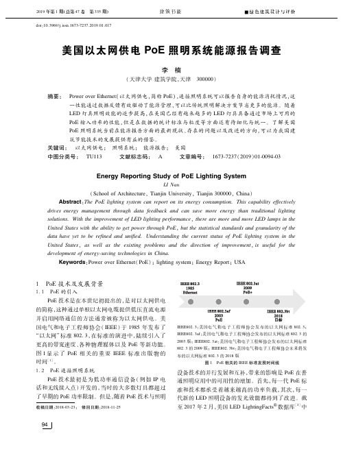
doi:10.3969?j.issn.16737237.2019.01.017
美国以太网供电 PE照明系统能源报告调查
李 楠
(天津大学 建筑学院,天津 300000)
1 PoE技术及发展背景
11 PoE的引入 PoE技术是在本世纪初提出的,是对以太网供电
的简称,这种通过单根以太网电缆提供低压直流电源 并启用网络通信的方法通常被称为以太网供电。美 国电气和电子工程师协会 (IEEE)于 1985年发布了 “以太网”标准 8023,在标准的演进中,陆续引入了 更高的带宽速度、各种物理媒体以及 PoE等新功能。 图 1显 示 了 PoE相 关 的 重 要 IEEE标 准 出 版 物 的 时间[1]。 12 PoE连接照明系统
94
李 楠 :美 国 以 太 网 供 电 PoE照 明 系 统 能 源 报 告 调 查
共有 45821个灯具,其中 22429个被归为室内灯具。 如果以 8023at2009中的 255W 输入限制为标准,可 以满足 21%的所有灯具和 24%的室内灯具;如果将 PD输入功率的上限设置为 71W(以太网联盟 2016), P8023bt2018中的最小 49W 将足以满足 50%的照明 设备和 71%的室内照明设备。除了能够开发更高输 出的 PoE灯具之外,P8023bt还有望为每个端口的多 个低输出照明设备供电。
图 1 PoE相关的 IEEE标准发展时间线
设备技术的并行发展和互补,带来的影响是 PoE在普 通照明应用中的可用性的增加。首先,每一代 PoE标 准和技术都 承 受 着 越 来 越 高 的 功 率 负 载,其 次,每 一 代新的 LED照明设备的发光效能都得到了改进。截 至 2017年 2月,美国 LED LightingFacts 数据库[2]中
Silvertel ANX-POE-Power 电源及Ethernet的电源技术应用指南说明书

IntroductionThere is a common misconception regarding the power available to a device with Power over Ethernet (PoE) over the advertised power available for each standard. This application note is created as a guide to help understand the power available, and where power can be lost in a PoE application, in order to assist in adhering to the correct power limits when implementing a Silvertel module into an application such that (classification) power limits are not being exceeded.PoE Power Limits OverviewThere have been three amendments to the IEEE802.3 specification regarding PoE, covering low power applications all the way up to applications with 90W of power usage. The first amendment to the specification was IEEE802.3af, this introduced Type 1 devices, which allowed for applications drawing up to 15.4W, with the IEEE802.3at amendment adding Type 2 devices for up to 30W of power, and finally the IEEE802.3bt added Type 3 and Type 4 devices for up to 90W applications.There are three elements to a PoE application, the Power Sourcing Equipment (PSE), Physical interface (PI) and the Powered Device (PD). The PSE is typically a switch or injector that supplies the DC power to the Ethernet cable alongside the data. The PI is the Ethernet cable that connects the PSE to the PD.PD ModulesFigure 1: PoE OverviewIt is important to note that the power figures stated above are not the power available to the PD application. They are the minimum amount of power the PSE should supply over any voltage measured at point A in Figure 1. This is typically the RJ45 connector of the switch or injector, and does not account for the power losses involved in transmission.Table 1: Available PowerTable 1 shows the guaranteed power available for each requested class at Point B in Figure 1, which is normally the RJ45 connector to the designed application device. This power available is calculated by using the minimum continuous supply voltage allowed for a PSE, of the given Type, over 100m of cable with the worst loop resistance allowable by the specification. In a real world situation, there will be more power available to the PD, as the cable resistance will be lower, the PSE may be outputting a higher voltage and the PSE may allow for a greater than minimum power to be drawn consistently. It is strongly recommended for reliable operation that any device being designed should only draw up to this guaranteed available power for any given class.What follows is an explanation of each stage where power can be lost in a PoE application and some general principles for reducing loss.Transmission LossesIn the first iteration of PoE, the cabling was rated to have a maximum pairset resistance of 20Ω for 100 metres of cable, this is the combined resistance for pairs 1-2 in series with pairs 3-6 (or 4-5 and 7-8 for Alt B operation). The maximum DC current in a type 1 system is 350mA; as a result up to 0.3502 x 20 = 2.45W can be lost in the cable. This is where the 12.95W minimum available power for a class 3 device from Table 1 is calculated 15.4 - 2.45 = 12.95W.With the announcement of Type 2 devices in the IEEE802.3at amendment, the maximum cable loop resistance was reduced to 12.5Ω. This reduces losses and adds a new higher maximum current of600mA down a pairset.Type 3 power systems, as detailed in amendment IEEE802.3bt, follow the same specifications as Type 2 devices but require the power be delivered over both pairsets (8 conductors), with class 6 devices able to draw up to 600mA on each pairset. For Type 4 devices, the maximum continuous current per pairset is increased up to 900mA for class 8 devices.Table 2: Transmission lossWhile the losses in transmission can be significant, and often not as extreme as those stated in Table 2, they are normally outside the control of the product manufacturer and as such, it is good practice to design the power envelop of a product to be within the figures above. If the manufacturer can specify the PSE used or the length and quality of cabling, then the minimum power level for the PD application can be increased according to the improved specifications.Polarity protectionPDs are required to be insensitive to the polarity of the power supplied over each pairset, as a result rectification is required. This rectification can be the source of a large amount of power loss in a PoE system, especially with higher power applications. In general there are three technologies when it comes to rectification, standard diode arrays, Schottky diode arrays featuring a reduced voltage drop, and ideal rectification using MOSFETs to virtually eliminate the voltage drop in rectification.To highlight the differences in technology a Silvertel Ag5412 PD Module was fitted to an EvalAgSil evaluation board and then tested with the three supplied different bridge rectifier modules and additionally a shorted bridge rectifier module created to be used as a comparison. Figure 2 shows the power dissipation of the bridge rectifiers by removing the power usage of the shorted bridge rectifier results from each of the bridge rectifier results.Figure 2: Bridge rectifier dissipationThe first bridge rectifier module utilises the DF01S which is a standard diode bridge rectifier with a forward voltage drop of approximately 0.9V per element. This is the cheapest option but will incur the most losses out of any rectification technology. This type of rectification is not recommended in Type 3 or 4 applications due to the significant losses and heat dissipation associated with the higher supply current.The Second bridge rectifier module utilises the lower voltage drop of Schottky barrier rectifiers in the form of 8x SS36 diodes. These feature a lower forward voltage drop of less than 0.4V, resulting in a significant drop in losses in comparison to the DF01S module.The final bridge rectifier module utilises active MOSFET rectification by using two FDMQ8205A ICs. This is the most expensive option, but offers the best performance in terms of losses. These provide a typical series resistance of 130mΩ on each pairset while power is supplied to the device, there will also be a small loss due to the internal drive circuitry.The Ag5412 PD Module can achieve an efficiency of 93.3% under normal conditions, but can only achieve 92.4% in this evaluation board setup; the additional loss will be due to the resistance of the traces and the sockets for the bridge rectifier module and the Ag5412 module. Table 3 shows the maximum output power that can be achieved before the 25.5W input power is reached.Table 3: Maximum Output PowerEMI SuppressionWhen it comes to EMI suppression, the recommended circuit Silvertel recommends is three 1kΩ@100MHz ferrite beads on both the V in+ and V in- rails. This is a general purpose recommendation that should provide more than adequate suppression for the vast majority of applications. This comes with the trade-off of efficiency, adding more than the required amount of suppression to a circuit reduces its efficiency and adds more heat to dissipate inside the enclosure.Even if a given level of suppression is required in an application, there are methods of reducing the losses. As standard, fitted to the EvalAgSil, are six Wurth 742792096 1kΩ @100MHz fer rite beads, these are rated for up to 1A with DC resistance of less than 0.3Ω in an 0805 package, however this equates to almost 1.8Ω resistance on a rail supplying up to 1.8A for a class 8 device.One method of reducing these losses is to increase the package size of the ferrite beads. As an example six Taiyo Yuden FBMH4525HM102NT ferrite beads were installed, these are still rated at 1kΩ @100MHz but are rated for up to 3A in an 1810 package and have DC resistance of less than 0.06Ω. This has a significant saving in power dissipation as can be seen in Figure 3, at the expense of a much larger board area required to fit the larger components.Figure 3: Ferrite bead dissipationData TransformerThe power dissipated across the Ethernet data transformer is small relative to the power delivered to the application but it is still a source of power loss. Fitted to the majority of Silvertel's evaluation boards including the EvalAgSil is the Wurth 749052050. As a comparison an Abracon ALAN310001-3J61DT transformer was fitted to the EvalAgSil. While both of these transformers are rated for up to 100W applications, the Wurth part is a more premium option, which as a result features lower DC resistance for similar levels of performance, this can be seen in Figure 4 with the Wurth data transformer dissipating less than half of the power of the Abracon transformer at 25W.For high power applications, it should be noted that this extra dissipation may result in a significant difference in temperature between the two transformers tested.Figure 4: Data transformer dissipationTrace LengthThe final element that should be considered for power losses is the traces in the board itself. For a standard 1oz copper PCB layer, a 10mil track will have a resistance of approximately 0.05Ω for every inch of track. Since these tracks are in series with each other, it can be assumed that there is 0.1Ω of resistance added for every inch the traces have to be routed to connect the Rj45 connector to the module’s pins.As a result it is recommended to fit the data transformer as close as possible to the RJ45, and fit the module close to the data transformer with as wide tracks as possible in a design avoiding vias and right angles were possible, as these will increase the resistance of the trace.ExampleHere is an example of where power losses can occur in a typical setup: an EvalAg6800 PSE supplied with 56V connected to an EvalAg5800 PD set to output 6.5A at 12V via a 0.5 metre patch cable. The losses in this example are only indicative of an actual setup as the evaluation boards contain unnecessary circuitry, sockets and longer than necessary tracks in order to help facilitate evaluation of the fitted modules. Figure 5: Example Setup∙Between the PSU and the V IN pins on the Ag6800 there is 0.93W loss. This is due to the cabling, connector and sockets on the module. ∙In the Ag6800 there is 0.61W consumed; 0.5W of this is the power and status LEDs on the EvalAg6800. ∙ Between the Ag6800 and the input to the bridge rectifiers there is 2.54W loss. This is lost in the cabling, RJ45 connectors and module sockets, the resistance of the two data transformers, and the traces on the evaluation boards.∙ Across the Schottky bridge rectifiers 1.23W is lost with a further 1.23W across the ferrites used for EMI suppression.∙The power draw of the Ag5800 for a 6.5A output and 52V supply is 10.6W. The measured supply voltage to the Ag5800 is 52.53V due to all the losses before the module. Added to this status LEDs and opto-coupler on the EvalAg5800 consume 0.4W. As you can see the losses in the evaluation board setup above are approximately 17.5W, meaning that in order to supply 78W of power to the load, there is approximately 94W output from the Ag6800, with a total of 95.5W drawn from the PSU.It is important to note that these are not fixed losses. In a designed system any losses due to the Ag6800 module sockets and the long traces on the evaluation boards will be reduced, and for example the LEDs are not necessary, they could be reduced or removed.Ag5800Ag6800。
POE配置说明
[H3C]
[H3C]int Ethernet 1/0/1//进入某个接口
[H3C-Ethernet1/0/1]poe enable//启用此接口的POE功能
[H3C-Ethernet1/0/1]quit
[H3C]
[H3C]poe-profile gao//设置POE团体功能
Saving configuration. Please wait...
Unit1 save configuration flash:/config.cfg successfully
%Apr 2 00:13:16:901 2000 H3CCFM/3/CFM_LOG:- 1 -Unit1 saved configuration successfully.
#Apr 2 00:14:44:172 2000 H3CCOMMONSY/5/REBOOT:- 1 -
Reboot device by command.
[H3C-Ethernet1/0/1]apply poe-profile gao
[H3C-Ethernet1/0/1]quit
[H3C]
[H3C]apply poe-profile gao interface Ethernet 1/0/5 to Ethernet 1/0/8//将POE团体功能应用到某些接口上
Port peak power :0 mW//此接口开启POE后的最高功率
Port average power :0 mW//此接口开启POE后的平均功率
Port current :0 mA
Port voltage :0 V
<H3C>save//保存当前配置
H3C PoE命令

i
命令手册 系统分册 PoE
第 1 章 PoE 配置命令
本文中标有“请以实际情况为准”的特性描述,表示各型号对于此特性的支持情况 可能不同,本节将对此进行说明。 H3C MSR 系列路由器的命令支持情况说明:
命令
PoE 命令
display poe pse interface display poe pse interface power
pseidmaxcurrentpeakaverageremainingpoweredguaranteedwportnum300200230205100204003003452902003050010012011030010命令手册系统分册poepoe配置命令111表15displaypoepowerusage命令显示信息描述表字段描述poecurrentpowerpse当前消耗功率总和poemaxpowerpoe最大功率poemaxguaranteedpowerpoe最大保证功率即电源提供给优先级为critical的pse的最大功率poeremainingallocatepowerpoe剩余可分配功率poe最大功率使能的pse的最大功率之和poeremainingguaranteedpowerpoe剩余保证功率poe最大保证功率设备中优先级为critical的pse最大功率之和poetotalpoweredportnumber当前设备正在供电的poe接口总数pseidpse编号maxpse最大功率currentpse当前功率peakpse峰值功率averagepse平均功率remainingguaranteedpse剩余保证功率pse最大保证功率该pse中优先级为critical的poe接口最大功率之和poweredportnumpse正在供电的poe接口数量117displaypoepse命令displaypoepse视图任意视图缺省级别1
迈普交换机常用指令
查看POE状态3026G:1.show power inlineS3026G#show power inlinePower Inline Status: OnPower Available: 185 WPower Used: 0 WPower Remaining: 185 WMin V oltage: 44 VMax V oltage: 57 VPolice: OffLegacy: OffDisconnect: AcMode: SignalHW Version: 30SW Version: 05.0.52. show power inline interface [ethernet <interface-number> | <interface-name>]Switch#show power inline interface ethernet1/1-6Interface Status Oper Power(mW) Max(mW) Current(mA) V olt(V)Priority Class------------ ------- ------ --------- ------- -----------Ethernet1/1 enable off 0 15400 0 0 high 0Ethernet1/2 enable off 0 15400 0 0 low 0Ethernet1/3 enable off 0 15400 0 0 low 0Ethernet1/4 enable off 0 15400 0 0 low 0Ethernet1/5 enable off 0 15400 0 0 low 0Ethernet1/6 enable off 0 15400 0 0 low 03、switch# show power fact-power显示结果描述与分析System Total Power : 150.0 W 系统总功率Total Power Allocated : 0.1 W 当前已使用的功率Available power : 149.9 W 剩余可用的功率2. switch# show power pd-status 0/3Power-Over-Ethernet port 0/3 status information:显示结果描述与分析Powered device current : 4.0mA PD的电流Powered device voltage : 46.8V PD的电压Powered device power : 0.1W PD的功率Powered device temperature :45℃POE端口的温度switch>?enable -- Enable Privileged modeexit -- Exit telnet sessionhelp -- helpshow -- Show running system informationswitch>1. 对特权用户配置命令“show interface ethernet 1”,只要输入“sh in e 1”即可。
- 1、下载文档前请自行甄别文档内容的完整性,平台不提供额外的编辑、内容补充、找答案等附加服务。
- 2、"仅部分预览"的文档,不可在线预览部分如存在完整性等问题,可反馈申请退款(可完整预览的文档不适用该条件!)。
- 3、如文档侵犯您的权益,请联系客服反馈,我们会尽快为您处理(人工客服工作时间:9:00-18:30)。
乙太網路供電系統 (PoE)
1.傳統遠端網路設備供電方式
所有的電子設備都需要電源才能夠執行工作,當然網路設備也是如此。
在網路通訊設備的領域裡,通常一部頭端網路設備(或稱本地設備)可以連接一個以上的遠端網路設備,例如一部四埠的乙太網路交換器(Ethernet Switch)可以同時連接四部的無線網路接取器(wireless Access Point)。
這表示這個區域網路需要五個電源才能讓這個區域網路工作,換句話說這五個市電插座是必要存在的設施。
有時在比較困難、不方便的位置,例如屋頂、樹上或是圍牆上,要裝設市電插座將會是一件令人頭痛且麻煩的事。
在現行電力系統中要運作網路設備,至少需要二條線,一條為電力線 (Power cable)另一條是網路線 (Cat.5, Cat.5e, even Cat.6)。
既是如此,市電的供應會直接影響遠端網路設備的架設位置,並可能因此導致網路設備的表現不如預期中的理想;
這也表示在現行電力系統中,網路設備的擴充和更換裝設位置會有很大的限制。
2.乙太網路供電系統的優勢 (PoE)
–一條網路線可同時傳送電力與網路訊號
A.網路設備的佈建更具彈性。
B.低建置成本、低營運成本與低維護成本。
C.安全保護機制。
IEEE 802.3af /IEEE 802.3at 能提供短路保護、過
低電壓保護、過電流保護、…等。
D.易於安裝,特別在於一些困難特殊的環境,例如屋頂、樹上和公共場
所(機場, 圖書館和街道的電線桿)。
E.中央監控。
有一些遠端的網路設備需要被伺服器或中央控制器,如
PoE 時鐘、PoE 電子看板、PoE 電子顯示器…等
3. 乙太網路供電系統(PoE)
乙太網路供電系統,IEEE802.3af 是由供電端(PSE)與受電端(PD)所組成的。
受電端經由網路線接受來自供電端的電力,再轉換成合適的電壓提供遠端網路設備所需的電力。
乙太網路供電系統與現行電力系統最大的差別在於,乙太網路供電系統可從本地網路設備端(Ethernet Switch),藉由一條網路線傳送電力和網路資料到遠端網路設備(wireless access point, IP camera, N etwork A ttached S torage (NAS),….and so on)。
乙太網路供電系統可提供比現行電力系統較低的維護費用,因為遠端網路設備不需要市電插座與電源轉換器(Power Adaptor)。
以下是二種典型的連接方式。
PD DC Output Mid-Span Mode
To AC Outlet
Ethernet data and 48Vdc power are delivered by a single Cat.5 cable Between Ethernet Switch (local device) and Wireless AP (remote device)
End Point Mode
4.兼容於IEEE802.3af 乙太網路供電系統的介紹
a.PoE 連接偵測
PSE會發送偵測訊號,用以偵測PD存在與否,若PD被驗證成功,再來就是進行PD功率偵測(power classification (Class 0 ~ 4)),以定義PD所需要的功率。
在通過PD所有的驗證後,PSE會提供48Vdc經由網路線到PD。
若是PD非兼容於IEEE 802.3af的情況,PSE會重復PD偵測的程序,此時即表示PD無法通過PSE 的驗證。
Table 1 PSE Power Classifications
Table 2 PD Power Classifications
b.隔離式與非隔離式的 PD
b1. 隔離式(Isolated) PD
隔離式的PD可提供輸入至輸出1500V隔離保護。
一旦有短路情況發生時,
這個隔離保護可有效增強短路保護,不論短路發生源是在於PSE到PD之間,
或是PD到負載(遠端網路設備)之間。
b2. 非隔離式(Non-isolated) PD
非隔離式的PD在短路保護上的表現較隔離式的PD差。
一旦有短路情況發生
時,很可能會造成PSE和PD兩端的傷害,因為非隔離式的PD的一、二次側
的地皆與PSE共地。
5.Mid-span & End-point 連接方式
a.End point 連接方式
b.Mid-span連接方式
6.IEEE802.3AT - PoE+系統
IEEE802.3AT是高功率PoE的解決方案,所以也稱為 PoE+. PoE+可支援25.5W的 PSE 端輸出功率,並且可用四對線提供 48Vdc 到 PD端。
如果在一個RJ45中使用PoE+二通道四對線的PSE供電方式,PSE端可提供高達50W的功率。