BU931L-T3P-T中文资料
BU9314KS中文资料
BU9314KS
688
元器件交易网 Optical disc ICs
BU9314KS
689
元器件交易网 Optical disc ICs
BU9314KS
690
元器件交易网 Optical disc ICs
FInputS
692
元器件交易网 Optical disc ICs
Analog system characteristics (unless otherwise noted, Ta = 25_C, VDD = 5V, and VC reference)
BU9314KS
FRecommended operating conditions (Ta = 25_C)
686
元器件交易网 Optical disc ICs
FBlock diagram
BU9314KS
687
元器件交易网 Optical disc ICs
FPin descriptions
元器件交易网 Optical disc ICs
Servo signal processor for CD use
BU9314KS
The BU9314KS is a servo signal processor for CD players that incorporates a double-speed, no-adjustment PLL, program servo, and signal processing block, and D / A converter on one chip. It operates off a low power supply voltage, and has low power consumption. FApplications Portable CD players, radio cassette players, and minicomponent systems. FFeatures 1) PLL on chip. Bit clock extraction possible with just a few external components. EFM data modulation is possible. 2) Frame synchronizing signal detection and protection. 3) Servo filters for focus, tracking, and sled are on chip. Characteristics can be controlled using commands from the controller. 4) Sub-code serial output pin provided. 5) Output pins for both P-code and Q-code. 6) CLV sequencer automatically determines the CLV mode. FAbsolute maximum ratings (Ta = 25_C)
PCS-931保护装置技术和使用说明书-国网版
目
录
1 概述 .................................................................................................................................................................... 1 1.1 应用范围 ...................................................................................................................................................... 1 1.2 保护配置 ...................................................................................................................................................... 1 1.3 装置特点 ...................................................................................................................................................... 2 2 技术参数....................................................................................................................................
SPS-93120MG中文资料
Optoway SPS-93120MG**********************************************************************************************************************************************************************************************************************************************************************************************************************************************OPTOWAY TECHNOLOGY INC. No .38, Kuang Fu S. Road, Hu Kou, Hsin Chu Industrial Park, Hsin Chu, Taiwan 303Tel: 886-3-5979798 Fax: 886-3-597973712/1/2005 V2.0 1SPS-93120MG (RoHS Compliant)3.3V / 1550 nm / Multirate SFP LC SINGLE-MODE TRANSCEIVER**********************************************************************************************************************************************************************FEATURESl Hot-Pluggable SFP Footprint LC Optical Transceiver l Small Form-Factor Pluggable (SFP) MSA compatible l Compliant with SONET OC-48 (LR-2) / SDH STM-16 (L-16.2)l Compliant with Fibre Channel 1x/2x SM-LC-L FC-PI l Compliant with IEEE 802.3z 1000BASE-ZX l 1550 nm DFB LD Transmitter l APD High Sensitivity Receiver l 31 dB Power Budget at Least l Distance up to 120 kml AC/AC Coupling according to MSA l Single +3.3 V Power Supply l RoHS Compliant l 0 to 70o C Operationl Class 1 Laser International Safety Standard IEC-60825 CompliantAPPLICATIONSl SONET OC-48 / SDH STM-16 l SONET OC-12 / SDH STM-4 l SONET OC-3 / SDH STM-1l Gigabit Ethernet / 1X/2X Fibre ChannelDESCRIPTIONThe SPS-93120MG series single mode transceivers is small form factor pluggable module for bi-directional serial optical data communications such as SONET OC-48 / SDH STM-16, Gigabit Ethernet 1000BASE-LX and Fibre Channel 1x/2x SM-LC-L FC-PI. It is with the SFP 20-pin connector to allow hot plug capability. This module is designed for single mode fiber and operates at a nominal wavelength of 1550 nm. A guaranteed minimum optical link budget of 31 dB is offered which can correspond to a link distance of over 120 km (assuming worst case fiber loss of 0.22 dB/km). The transmitter section uses a multiple quantum well 1550 nm DFB laser and is a class 1 laser compliant according to International Safety Standard IEC-60825. The receiver section uses an integrated InGaAs detector preamplifier (IDP) mounted in an optical header and a limiting post-amplifier IC.LASER SAFETYThis single mode transceiver is a Class 1 laser product. It complies with IEC-60825 and FDA 21 CFR 1040.10 and 1040.11. The transceiver must be operated within the specified temperature and voltage limits. The optical ports of the module shall be terminated with an optical connector or with a dust plug.ORDER INFORMATIONP/No.Bit Rate(Mb/s) SONET /SDH Distance (km) Wavelength (nm) Package Temp. (oC) TX Power (dBm) RX Sens. (dBm) RoHS Compliant SPS-93120MGMultirate*120 1550 DFB LC SFP0 to 70 5 to 1 -30 YesMultirate*: 2.67 Gb/s / OC-48 / 2X FC / GbE / 1X FC / OC-12 / OC-3Absolute Maximum RatingsParameterSymbol Min Max Units NotesStorage TemperatureTstg -40 85 o COperating Case Temperature Topr 0 70 o C Air flow 1m/sec Power Supply VoltageVcc-0.53.6VRecommended Operating ConditionsParameterSymbol Min Typ Max Units / NotesPower Supply VoltageVcc 3.13 3.3 3.47 VOperating Case Temperature Topr 0 70 oC / air flow 1m/secPower Supply Current I CC (TX+RX)230 300 mA Data Rate12524882670Mb/sTransmitter Specifications (0o C < Topr < 70o C, 3.13V < Vcc < 3.47V)Parameter Symbol Min Typ Max Units NotesOpticalOptical Transmit Power Po 1 --- 5 dBm 1Output Center Wavelength λ1500 1570 nmOutput Spectrum Width ∆λ--- --- 1 nm -20 dB WidthSide Mode Suppression Ratio SMSR 30 dBExtinction Ratio E R8.2 --- --- dBOutput Eye Compliant with Telecordia GR-253-GORE and ITU-T Recommendation G.957Optical Rise Time t r150 ps 20 % to 80% Values Optical Fall Time t f150 ps 20 % to 80% Values Relative Intensity Noise RIN -120 dB/HzDispersion Penalty 2.5 dB 2ElectricalData Input Current – Low I IL-350 µAData Input Current – High I IH350 µADifferential Input Voltage V IH - V IL0.5 2.4 V Peak-to-PeakTX Disable Input Voltage – Low T DIS, L0 0.5 V 3TX Disable Input Voltage – High T DIS, H 2.0 Vcc V 2TX Disable Assert Time T ASSERT10 µsTX Disable Deassert Time T DEASSERT 1 msTX Fault Output Voltage -- Low T FaultL0 0.5 V 4TX Fault Output Voltage -- High T FaultH 2.0 Vcc+0.3 V 41. Output power is power coupled into a 9/125 µm single mode fiber.2. Specified at 2400 ps/nm dispersion over G.652/G.654 fiber with center wavelength range of 1500 to 1580 nm.3. There is an internal4.7K to 10K ohm pull-up resistor to VccTX.4. Open collector compatible, 4.7K to 10K ohm pull-up to Vcc (Host Supply Voltage).Receiver Specifications(0o C < Topr < 70o C, 3.13V < Vcc < 3.47V)Parameter Symbol Min Typ Max Units NotesOpticalSensitivity @ OC-48Sens1 -9 -30 dBm 5 Sensitivity @2X Fibre Channal Sens2 -9 -30 dBm 6 Sensitivity @Gigabit Ethernet Sens3 -9 -30 dBm 6 Sensitivity @OC-12 Sens4 -9 -30 dBm 5 Sensitivity @OC-3 Sens5 -18 -30 dBm 5Signal Detect -- Asserted Pa --- -28 dBm Transition: low to high Signal Detect -- Deasserted Pd -40 --- --- dBm Transition: high to low Signal detect -- Hysteresis 1.0 --- dBWavelength of Operation 1100 --- 1600 nmElectricalDifferential Output Voltage V OH– V OL0.6 2.0 VOutput LOS Voltage -- Low V OL0 0.5 V 7Output LOS Voltage -- High V OH 2.0 Vcc+0.3 V 75. Measured at 223-1 PRBS at BER 1E-10.6. Measured at 27-1 PRBS at BER 1E-12 .7. Open collector compatible, 4.7K to 10K ohm pull-up to Vcc (Host Supply Voltage).*********************************************************************************************************************************************************************** OPTOWAY TECHNOLOGY INC. No.38, Kuang Fu S. Road, Hu Kou, Hsin Chu Industrial Park, Hsin Chu, Taiwan 303***********************************************************************************************************************************************************************OPTOWAY TECHNOLOGY INC. No .38, Kuang Fu S. Road, Hu Kou, Hsin Chu Industrial Park, Hsin Chu, Taiwan 303PINSignal NameDescriptionPINSignal Name Description1 TX GND Transmitter Ground11 RX GND Receiver Ground2 TX Fault Transmitter Fault Indication12 RX DATA OUT- Inverse Receiver Data Out 3 TX Disable Transmitter Disable (Module disables on high or open)13 RX DATA OUT+ Receiver Data Out 4 MOD-DFE2 Modulation Definition 2 – Two wires serial ID Interface14 RX GND Receiver Ground5 MOD-DEF1 Modulation Definition 1 – Two wires serial ID Interface15 Vcc RX Receiver Power – 3.3V ±5% 6 MOD-DEF0 Modulation Definition 0 – Ground in Module16 Vcc TX Transmitter Power – 3.3V ±5% 7 N/C Not Connected 17 TX GNDTransmitter Ground 8 LOS Loss of Signal 18 TX DATA IN+ Transmitter Data In9 RX GND Receiver Ground 19 TX DATA IN- Inverse Transmitter Data In 10RX GNDReceiver Ground20TX GNDTransmitter GroundModule DefinitionModule DefinitionMOD-DEF2 PIN 4 MOD-DEF1 PIN 5 MOD-DEF0 PIN 6 Interpretation by Host 4SDASCLLV-TTL LowSerial module definitionprotocolModule Definition 4 specifies a serial definition protocol. For this definition, upon power up, MOD-DEF(1:2) appear as no connector (NC) and MOD-DEF(0) is TTL LOW. When the host system detects this condition, it activates the serial protocol. The protocol uses the 2-wire serial CMOS E 2PROM protocol of the ATMEL AT24C01A/02/04 family of components.*********************************************************************************************************************************************************************** OPTOWAY TECHNOLOGY INC. No.38, Kuang Fu S. Road, Hu Kou, Hsin Chu Industrial Park, Hsin Chu, Taiwan 303。
BU931-T3P-T中文资料
350
300
Note: 1. Wafer area should be than 50% 2.The quantity of cracked wafers should be less than 10% per shipment. 3.Auerage yield should be more than 50% per wafer, 80% per shipment.
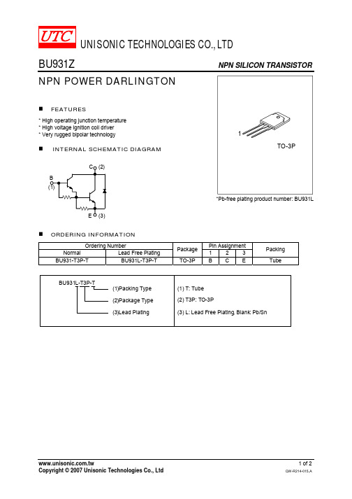
NPN SILICON TRANSISTOR
RATINGS 350 5 10 15 1 5 125 +175 -65 ~ +175
UNIT V V A A A A W
ELECTRICAL CHARACTERISTICS
PARAMETER Collector Cut-off Current Emitter Cut-off Current Collector-Emitter Saturation Voltage Base-Emitter Saturation Voltage DC Current Gain Diode Forward Voltage Inductive Load Storage Time / Fall Time tF SYMBOL ICEO IEBO VCL VCE(SAT)1 VCE(SAT)2 VBE(SAT)1 VBE(SAT)2 hFE VF tS TEST CONDITIONS VCE = 300 V VEB = 5 V IC = 100mA IC = 7 A, IB = 70 mA IC = 8 A, IB = 100 mA IC = 7 A, IB = 70 mA IC = 8 A, IB = 100 mA VCE = 10 V, IC = 5 A IF = 8 A VCC = 12 V, Vclamp = 300 V L = 7 mH IC = 7 A, IB = 70 mA VBE = 0, RBE = 47Ω MIN TYP MAX UNIT 100 µA 20 mA 500 V 1.6 V 1.8 V 2.2 V 2.4 V 2.5 15 0.5 V µs µs
平望 PVT-9315S 工控板 Windows CE 5.0 用户手册说明书

PVT-9315S 工控板说明书Windows CE 5.0 用户手册版本号: 1.0杭州平望科技有限公司2007年1月目录1工具使用2操作系统镜像文件的下载和运行2.1 烧写eboot.nb0到Flash中2.2 通过CF卡下载镜像文件2.3 通过以太网下载镜像文件1工具使用编译和下载Cirrus Logic EP931x Windows CE .net BSP 到PVT-9315S主板需要以下软件工具和相关硬件:·Download.exe 该程序为eboot 下载程序·PVT-9315S主板·交叉以太网线和dhcp服务程序·交叉串口线·USB鼠标·USB键盘(可选)·Windows 5.0 Platform Builder (ARM4I安装支持)PC机应该具有如下配置:·800Mhz 处理器·10G 的硬盘空间用来安装Platform Builder(新建一个工程大概有0.5G左右) ·Windows 2000 SP3或者Windows XP·以太网卡·串行端口2操作系统镜像文件的下载和运行2.1 烧写eboot.nb0到Flash中(1)将PVT-9315S板上J2短接,使能EP9315内部串口下载,将交叉串口分别一端接PC机上的COM1口,另一端接PVT-9315S板的UART1(J14端口)。
(注意不要使用其他的串口通讯程序打开PC上与PVT-9315S主板相连接的串口)先不要打开PVT-9315S板上电源。
(2)将光盘附带的文件eboot.nb0拷贝到download.exe 的同一个目录中,在命令提示符下输入命令:(输入命令的目录应为download.exe 所在目录)download eboot.nb0如下图所示:(3)出现上图所示提示后,将PVT-9315S 电源开关打开,或按复位键,即会启动串口下载并执行分段烧写,如下图所示:(4)下图显示烧写成功:(5)在烧写EBOOT成功后,断开电源,摘掉J2跳线,使PVT-9315S能从FLASH 启动,将PC串口与PVT-9315S主板的UART3(J13端口)连接,打开超级终端,新建一个连接,设置PC上相应串口波特率为[38400],[1]位停止位,无奇偶校验和流控。
LMV931 中文资料

Single Supply Amplifier Circuits
3
2-3
Why Use Single Supply • Single supply circuit is the market trend
– Digital circuit normally uses single supply – Single supply analog circuit interfaces to digital
Vcm range is equal to output voltage range
14
2-14
Railபைடு நூலகம்to Rail Input
15
2-15
Single-supply Op-Amp Biasing
VIN = 0.01V to 1V
VO = 1V to 4.5V
A/D
16
与输入直流偏置和输出直流偏置都可以处在地(0V)电位的由双电源供电的常规运算放大器不同,对单电源 运算放大器进行偏置设置工作具有更大的挑战性。下面我们将要考察几种情况,这时放大器的输入电压范围 要变换为规定的输出电压范围,通常用来供给 ADC 的输入。
R5 -
500
RR Input
Q1
Q2
R1 Q3
Vcc R2
Vbias1 Q4
R3
R4
Q5
Q6
Vss
Vss
D1
D2
D3
D4
R6 +
500
+ Output to High drive
-
-
Vcc I1
R7 Q7
R8 Q8
Vcc
1.4 Q9
Viscor LTRI-LED三光源LED亮灯架型号说明书
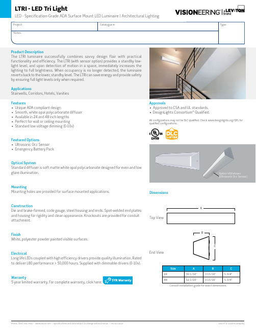
Option V69 shown(Ultrasonic Occ Sensor)Features• Unique ADA compliant design• Smooth, white opal polycarbonate diffuser • Available in 24 and 48 inch lengths • Perfect for wall or ceiling mounting • Standard low voltage dimming (0-10v)Featured Options• Ultrasonic Occ Sensor • Emergency Battery PackOptical SystemStandard diffuser is soft matte white opal polycarbonate designed for even and low glare illumination.MountingMounting holes are provided for surface mounted applications.ConstructionDie and brake-formed, code gauge, steel housing and ends. Spot-welded end plates and housing for rigidity and clean appearance. Knockouts are provided for conduit attachment.FinishWhite, polyester powder painted visible surfaces.ElectricalLong life LEDs coupled with high efficiency drivers provide quality illumination. Rated to deliver L80 performance > 50,000 hours. Supplied with dimmable drivers (0-10v).Warranty5 year limited warranty. For complete warranty, click here:Consult installation guide for exact dimensions.Product DescriptionThe LTRI luminaire successfully combines savvy design flair with practical functionality and efficiency. The LTRI (with sensor option) provides a standby low-light level, and upon detection of motion in a space, immediately increases the lighting to full brightness. When occupancy is no longer detected, the luminaire reverts back to the lower, standby level. The LTRI can save energy and provide safety by ensuring full light levels only when required.ApplicationsStairwells, Corridors, Hotels, Vanities Approvals• Approved to CSA and UL standards.• DesignLights Consortium ® Qualified.All configurations may not be DLC qualified. Check /QPL for qualified configurations..DimensionsTop ViewEnd ViewOrder Key50K - 5000K 010L - 1000016L - 1600018L - 1800037L - 3700050L - 5000Driver OptionsB15 Bi-Level Step Dimming (50/100)(Not available in 24-inch length or 347V)B39 Emergency Lighting Battery Pack - LED(Not available in 24-inch length)Housing Construction OptionsC03 Fasteners Tamper ProofC65 Housing for Front Facing SensorFinish OptionsWhite, polyester powder painted is standardF01 Black SatinF14 Silver ReflectivePackaging OptionsK0 Bulk Pack/Pallet Packed and/or WrappedK1Pack SingleSensor Options(Not to be used in conjunction with B15 option)(Not suitable for chain/cable suspension)V69 Ultrasonic Occupancy Sensor(Capable of 0% / 10% / 25% / 50%)Controls OptionsTo visw the controls guide Click Here.Other options may be available, consult factory. Specifications and datasubject to change without notice.48”EXAMPLE: LTRI48- LED835K037LUNV-V6924”Sensor PlacementPerformance DataValues based on 840K with standard lens at 25CPhotometrics。
BU931 BU931Z BU931ZL NPN型功率达林顿晶体管

BU931ZL
NPN 功率达林顿晶体管
用途
用于驱动高压电子点火线圈和电机控制
特点
● 内置钳位稳压和续流二极管
绝对最大额定值
缩写 Vcbo Vceo Vebo
Ic Icm Ib Ibm
Pto-基极 电压 集电极-发射极 电压 发射极-基极 电压 集电极电流 集电极峰值电流 基极电流 基极峰值电流 耗散功率 Tc=25℃/带散热片 结温 贮存温度
单位 V V V A A A A
W
℃ ℃
数值 350 350
5 10 15 1 2
60
175 -65~175
B B
TO-263-2L
TO-220
晶体管内部等效电路图
电参数(Tamb = 25℃)
缩写 Iceo Vceo Iebo
参数 集电极-发射极 电流 集电极-发射极 电压 发射极-基极 电流
Vce(sat) 集电极-发射极 饱和电压
Vbe(sat) 基极-发射极 饱和电压
hFE VfEC VCL
直流增益 二极管正向电压 钳位电压
丹东华奥电子有限公司
Automobile Semiconductor
单位 µA V mA V
V
V V
数值
≤50 ≥350 ≤20 ≤1.8 ≤1.8 ≤2.2 ≤2.5 ≥300 ≤2.5
350~500
测试条件
Vce=300V Ic=100mA Ib=0 Veb=5.0V Ico=0 Ic=8A Ib=110mA Ic=10A Ib=250mA Ic=8A Ib=110mA Ic=10A Ib=250mA Ic=5A Vce=5V
If=10A Ic=100mA
LRB751V-40T1中文资料
10
1 Ta = 25oC 100n Ta = -25oC Typ. pulse measurement 5 10 15 20 25 30 REVERSE VOLTAGE : VR (V) 35
10n
1n 0
Fig. 2 Reverse characteristics
DEVICE MARKING
LRB751V-40T1= 5E
ELECTRICAL CHARACTERISTICS(TA = 25°C)
Parameter Forward voltage Reverse current Capacitance between terminals Symbol VF IR CT Min. Typ 2.0 Max. 0.37 0.5 Unit V µA pF Conditions IF=1mA VR=30V VR=1V,f=1MHz
LRB751V-40T1–1/3
元器件交易网
LESHAN RADIO COMPANY, LTD.
LRB751V-40T1 Electrical characteristic curves(TA = 25°C)
1000m Typ. pulse measurement 100m 10m 1m 100 10 1
LRB751V- 40T1
Construction
silicon epitaxial planar
SC-76/SOD-323
ORDERING INFORMATION
Device LRB751V-40T1 LRB751V-40T1G (Pb-Free) Package SOD-323/SC-76 SOD-323/SC-76 Shipping 3000/Tape&Reel 3000/Tape&Reel
9N90L-T3P-T中文资料
UNISONIC TECHNOLOGIES CO., LTD9N90 Power MOSFET900V N-CHANNEL MOSFETDESCRIPTIONThe UTC 9N90 uses UTC’s advanced proprietary, planar stripe, DMOS technology to provide excellent R DS(ON), low gate charge and operation with low gate voltages. This device is suitable for use as a load switch or in PWM applications.FEATURES* R DS(ON) = 1.4Ω @V GS = 10 V* Ultra low gate charge ( typical 45 nC )* Low reverse transfer capacitance ( C RSS = typical 14 pF ) * Fast switching capability * Avalanche energy specified* Improved dv/dt capability, high ruggednessSYMBOL1.Gate*Pb-free plating product number: 9N90LORDERING INFORMATIONOrdering Number Pin AssignmentNormal Lead Free Plating Package 1 2 3Packing9N90-T3P-T 9N90L-T3P-T TO-3P G D STubeABSOLUTE MAXIMUM RATING (T C =25℃, unless otherwise specified)PARAMETER SYMBOL RATINGS UNITDrain-Source Voltage V DSS 900 V Gate-Source Voltage V GSS ±30 VContinuous Drain Current(T C = 25℃) I D 9.0 A Pulsed Drain Current (Note 1) I DM 36 A Avalanche Current (Note 1) I AR 9.0 ASingle Pulsed(Note 2)E AS 900Avalanche Energy Repetitive(Note 1) E AR 28mJPeak Diode Recovery dv/dt (Note 3) dv/dt 4.0 V/ns 280 WPower Dissipation Derate above 25℃ P D2.22 W/℃ Junction Temperature T J 125 ℃ Operating Temperature T OPR -20 ~ +85 ℃ Storage Temperature T STG -40 ~ +150 ℃ Note: Absolute maximum ratings are those values beyond which the device could be permanently damaged. Absolute maximum ratings are stress ratings only and functional device operation is not implied.THERMAL CHARACTERISTICSPARAMETER SYMBOL MIN TYP MAX UNITJunction-to- Ambient θJA 40 ℃/W Junction-to-Case θJC 0.45 ℃/WELECTRICAL CHARACTERISTICS (T J =25℃, unless otherwise specified)PARAMETER SYMBOL TEST CONDITIONS MIN TYP MAX UNIT OFF CHARACTERISTICSDrain-Source Breakdown Voltage BV DSS V GS = 0 V, I D = 250 μA 900 V Drain-Source Leakage Current I DSS V DS = 900 V, V GS = 0 V 10 μAForward I GSSF V GS = 30 V, V DS = 0 V 100Gate-Body Leakage CurrentReverse I GSSRV GS = -30 V, V DS = 0 V -100nA Breakdown Voltage TemperatureCoefficientBV △DSS /△T J I D = 250 μA, Referenced to 25℃ 0.99 V/℃ON CHARACTERISTICS Gate Threshold Voltage V GS(TH) V DS = V GS , I D = 250 μA 3.0 5.0V Static Drain-Source On-Resistance R DS(ON) V GS = 10 V, I D = 4.5 A 1.12 1.4Ω DYNAMIC PARAMETERS Input Capacitance C ISS 2100 2730pFOutput Capacitance C OSS 175 230pFReverse Transfer Capacitance C RSSV DS = 25 V, V GS = 0 V,f = 1.0 MHz14 18 pF SWITCHING CHARACTERISTICS Turn-On Delay Time t D(ON) 50 110nsTurn-On Rise Time t R 120 250ns Turn-Off Delay Time t D(OFF) 100 210nsTurn-Off Fall Time t F V DD = 4500V, I D =11.0 A, R G = 25Ω (Note 4, 5) 75 160ns Total Gate Charge Q G 45 58 nCGate-Source Charge Q GS 13 nCGate-Drain Charge Q GDV DS = 720V, I D = 11.0A,V GS = 10 V (Note 4, 5)18 nCELECTRICAL CHARACTERISTICS(Cont.)PARAMETER SYMBOL TEST CONDITIONS MIN TYP MAX UNITDRAIN-SOURCE DIODE CHARACTERISTICS AND MAXIMUM RATINGS Drain-Source Diode Forward Voltage V SD V GS = 0 V, I S = 9.0 A 1.4VMaximum Continuous Drain-SourceDiode Forward CurrentI S 9.0 AMaximum Pulsed Drain-Source DiodeForward CurrentI SM 36 AReverse Recovery Time t RR 550 ns Reverse Recovery Charge Q RR V GS = 0 V, I S = 9.0 A,d IF / dt = 100 A/μs (Note 4) 6.5 μCNote 1. Repetitive Rating : Pulse width limited by maximum junction temperature2. L = 21mH, I AS = 9.0A, V DD = 50V, R G = 25 Ω, Starting T J = 25℃3. I SD ≤ 9.0A, di/dt ≤ 200A/μs, V DD ≤ BV DSS , Starting T J = 25℃4. Pulse Test : Pulse width ≤ 300μs, Duty cycle ≤ 2%5. Essentially independent of operating temperatureTEST CIRCUITFig. 2A Switching Test Circuit Fig. 2B Switching WaveformsFig. 3A Gate Charge Test Circuit Fig. 3B Gate Charge WaveformFig. 4A Unclamped Inductive Switching Test Circuit Fig. 4B Unclamped Inductive Switching WaveformsTEST CIRCUIT(Cont.)TYPICAL CHARACTERISTICSTYPICAL CHARACTERISTICS(Cont.)D r a i n -S o u r c e B r e a k d o w n V o l t a g e , B V D S S (N o r m a l i z e d )D r a i n -S o u r c e O n -R e s i s t a n c e , R D S (O N ) (N o r m a l i z e d )D r a i n C u r r e n t , I D (A )D r a i n C u r r e n t , I D (A )。
LFP-931A型数字电流差动保护装置技术说明书
检同期允许误差 检同期有压元件
检无压元件
<5% <0.25V 0.1In 25In 0~10s
±2.5%
< ±3° 0.7UN ±5% 0.3UN ±5%
3.5 光纤接口技术指标:
3.5.1 发送功率:
-20dBm(1.3μm, 多模光纤)
-24dBm(1.3µm, 单模光纤)
装置的重合闸配合时, 可考虑用压板仅投入一套重合闸装置。
2.9 键盘操作简单, 采用菜单式工作方式, 仅有+、-、上、下、左、右等共九个按键, 非常易于掌握。
2.10 配有液晶信号显示。正常运行时, 可显示所测量的电流, 电压幅值和相位, 线路 故障时则显示跳闸相别, 跳闸类型和测距结果。
2.11 装置背后端子有一个串行口,可与打印机相联。另有一个串行口作为对外通讯用。
LFP-931A型数字电流差动保护装置
1. 装置的应用
本装置为由十六位微处理器实现的全数字式超高压线路快速保护装置。 本装置包括以分相电流差动元件为快速主保护, 有三段式相间和接地距离作为后备 的全套保护。 保护有分相出口,可作为220KV及以上电压等级的输电线主保护或后备保护。
2. 装置的性能特征
以上四个部分结合,保证了距离保护在各种故障情况下的快速开放。
2.8 自动重合闸部分 自动重合闸用于单或双母线方式, 可选用单相重合, 三相重合或综合重合的方式,
可根据故障的严重程度引入闭锁重合闸的方式。 重合闸的起动有保护起动和开关位置不对应起动二种, 当与本公司其它产品一起
使用, 有二套重合闸时,二套装置的重合闸可以同时投入, 不会出现二次重合, 与其它
2.3 差动继电器保护全线路跳闸时间小于25ms(故障电流大于额定电流),小故障电流时 动作时间小于30ms
HS-P931 三相多功能电能表 网络通讯 输入输出
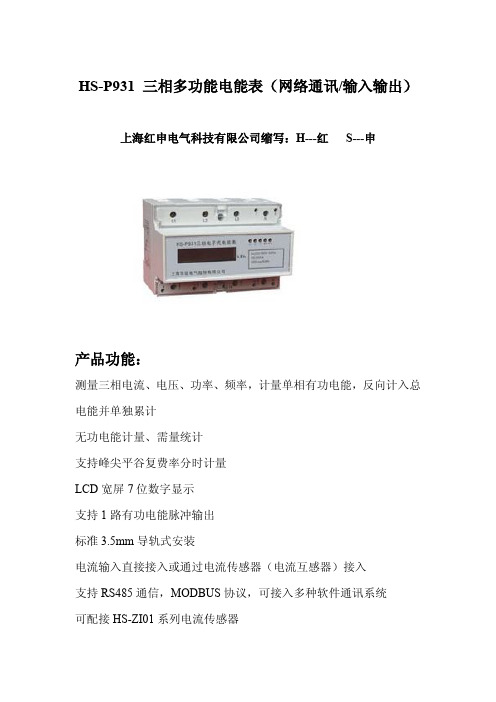
HS-P931三相多功能电能表(网络通讯/输入输出)上海红申电气科技有限公司缩写:H---红S---申
产品功能:
测量三相电流、电压、功率、频率,计量单相有功电能,反向计入总电能并单独累计
无功电能计量、需量统计
支持峰尖平谷复费率分时计量
LCD宽屏7位数字显示
支持1路有功电能脉冲输出
标准3.5mm导轨式安装
电流输入直接接入或通过电流传感器(电流互感器)接入
支持RS485通信,MODBUS协议,可接入多种软件通讯系统
可配接HS-ZI01系列电流传感器
产品系列:
HS-P931C三相多功能电能表
HS-P931E三相多功能电能表
企业简介
企业机构:上海红申电气科技有限公司
法人代表:刘经理
注册资本:人民币5000万
经营模式:生产加工、经销批发
员工数量:800-1200人
主要市场:大陆;西欧;东南亚
;客户类型:国家电网公司、成套厂、大中型建筑工程所属行业:配电输电设备;开关;
产品信息:成套大类(高低压电器、成套设备、箱变)品牌:红申HS。
BUL310FP中文资料
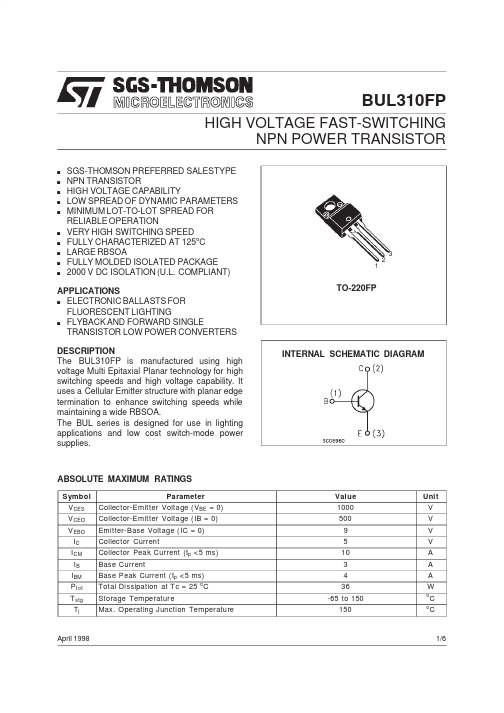
BUL310FPHIGH VOLTAGE FAST-SWITCHINGNPN POWER TRANSISTORs SGS-THOMSON PREFERRED SALESTYPE s NPN TRANSISTORs HIGH VOLTAGE CAPABILITYs LOW SPREAD OF DYNAMIC PARAMETERS sMINIMUM LOT-TO-LOT SPREAD FOR RELIABLE OPERATIONs VERY HIGH SWITCHING SPEED s FULLY CHARACTERIZED AT 125o C s LARGE RBSOAs FULLY MOLDED ISOLATED PACKAGE s2000V DC ISOLATION (PLIANT)APPLICATIONS s ELECTRONIC BALLASTS FOR FLUORESCENT LIGHTING s FLYBACK AND FORWARD SINGLETRANSISTOR LOW POWER CONVERTERS DESCRIPTIONThe BUL310FP is manufactured using high voltage Multi Epitaxial Planar technology for high switching speeds and high voltage capability.It uses a Cellular Emitter structure with planar edge termination to enhance switching speeds while maintaining a wide RBSOA.The BUL series is designed for use in lighting applications and low cost switch-mode power supplies.INTERNAL SCHEMATIC DIAGRAMApril 1998TO-220FP123ABSOLUTE MAXIMUM RATINGSSymbol ParameterValue Unit V CES Collector-Emitter Voltage (V BE =0)1000V V CEO Collector-Emitter Voltage (IB =0)500V V EBO Emitter-Base Voltage (IC =0)9V I C Collector Current5V I CM Collector Peak Current (t p <5ms)10A I B Base Current3A I BM Base Peak Current (t p <5ms)4A P t ot Total Dissipation at Tc =25oC 36WT stg Storage Temperature-65to 150o C T jMax.Operating Junction Temperature150oC1/6THERMAL DATAR t hj-ca se R t hj-amb Thermal Resistance Junction-Case MaxThermal Resistance Junction-Ambient Max3.562.5o C/Wo C/WELECTRICAL CHARACTERISTICS(T case=25o C unless otherwise specified)Symbol Parameter Test Conditions Min.Typ.Max.UnitI CES Collector Cut-offCurrent(V BE=0)V CE=1000VV CE=1000V T j=125o C100500µAµAI CEO Collector Cut-offCurrent(I B=0)V EC=400V250µAV CEO(sus)Collector-EmitterSustaining VoltageI C=100mA L=25mH500VV EBO Emitter-Base Voltage(I C=0)I E=10mA9VV CE(sat)∗Collector-EmitterSaturation Voltage I C=1A I B=0.2AI C=2A I B=0.4AI C=3A I B=0.6A0.50.71.1VVVV BE(s at)∗Base-EmitterSaturation Voltage I C=1A I B=0.2AI C=2A I B=0.4AI C=3A I B=0.6A11.11.2VVVh FE∗DC Current Gain I C=10mA V CE=5VI C=3A V CE=2.5V 1010t s t f INDUCTIVE LOADStorage TimeFall TimeI C=2A I B1=0.4AV BE(of f)=-5V R BB=0ΩV CL=250V L=200µH1.2801.9160µsnst s t f INDUCTIVE LOADStorage TimeFall TimeI C=2A I B1=0.4AV BE(of f)=-5V R BB=0ΩV CL=250V L=200µHT j=125o C1.8150µsns∗ Pulsed:Pulse duration=300µs,duty cycle1.5%Safe Operating Areas Derating Curve BUL310FP2/6DC Current GainCollector Emitter Saturation Voltage Inductive Fall Time DC Current GainBase Emitter Saturation VoltageInductive Storage TimeBUL310FP3/6BUL310FPReverse Biased SOA RBSOA and Inductive Load Switching TestCircuit(1)Fast electronic switch(2)Non-inductive Resistor(3)Fast recovery rectifier4/6DIM.mm inch MIN.TYP.MAX.MIN.TYP.MAX.A 4.4 4.60.1730.181B 2.5 2.70.0980.106D 2.5 2.750.0980.108E 0.450.70.0170.027F 0.7510.0300.039F1 1.15 1.70.0450.067F2 1.15 1.70.0450.067G 4.95 5.20.1950.204G1 2.4 2.70.0940.106H 1010.40.3930.409L2160.630L328.630.6 1.126 1.204L49.810.60.3850.417L615.916.40.6260.645L799.30.3540.366Ø3 3.20.1180.126L2ABDEHGL6¯FL3G 1123F 2F 1L7L4TO-220FP MECHANICAL DATABUL310FP5/6Information furnished is believed to be accurate and reliable.However,SGS-THOMSON Microelectronics assumes no responsability for the consequences of use of such information nor for any infringement of patents or other rights of third parties which may results from its use.No license is granted by implication or otherwise under any patent or patent rights of SGS-THOMSON Microelectronics.Specifications mentioned in this publication are subject to change without notice.This publication supersedes and replaces all information previously supplied.SGS-THOMSON Microelectronics products are not authorized for use as critical components in life support devices or systems without express written approval of SGS-THOMSON Microelectonics.©1998SGS-THOMSON Microelectronics -Printed in Italy -All Rights ReservedSGS-THOMSON Microelectronics GROUP OF COMPANIESAustralia -Brazil -Canada -China -France -Germany -Italy -Japan -Korea -Malaysia -Malta -Morocco -The Netherlands -Singapore -Spain -Sweden -Switzerland -Taiwan -Thailand -United Kingdom -U.S.A...BUL310FP6/6。
LT-S-(L) 技术手册说明书

Contents1.Overview (3)2.Product Specification (4)2.1Nomenclature (4)2.2Product Line (4)2.3Compressor specification table (4)2.4Operating range graph (6)3.Construction & Functions (8)3.1Design Features (8)3.2Capacity modulation system (8)3.2.1Step type capacity modulation system (10)3.2.2Stepless type capacity modulation system (14)3.2.3The Location of the Solenoid Valves (19)4.Lubricant (21)4.1Lubricant Specification (21)4.2The Replacement of Lubricant (22)4.3.1Oil Change Schedule (22)4.3.2Pre-cautions for changing oil (22)5.System Application (24)5.1Piping Design (24)5.1.1Suction and Discharge Piping Layout (24)5.1.2Economizer Piping Layout (26)5.1.3Minimum pressure valve (26)5.1.4Liquid Line Filter Dryer (27)5.1.5Sight Glass with Moisture Indicator (27)5.2Oil Line (28)5.2.1Oil Supply (28)5.2.2Lubrication and Capacity Control Modulation (28)5.2.3Compressor chamber injection system (28)5.2.4Protection in Oil Circuit (29)1)Oil temperature (29)2)Oil filter (30)3)Oil pressure differential (31)4)Oil level protection (31)5.2.5Oil cooling system (31)1)Air cooling type (33)2)Water cooling type (33)3)Refrigerant oil cooling (34)5.3Motor Liquid Injection Cooling (34)5.4Economizer System (35)5.4.1Economizer System with Sub Cooler (35)5.4.2Economizer System with Flash Type Subcooler (36)5.5Recommended System Layout (38)Figure 5-14. High Temperature Heat Pump Recommend System Layout (38)6.Electrical Design (39)6.1Electrical parameters and design (39)6.1.1Y-Δ Start (39)6.1.2Power requirements (40)6.1.3MCC&LRA (41)pressor Installation (45)7.1Open compressor wooden crate (45)7.2Compressor Lifting (45)7.3Compressor installation (46)8.Operation and Maintenance (48)8.1Compressor commissioning check (48)1.1.1Check list before Start (48)8.1.2Check list during operation (49)8.2rouble shooting table (50)9.Dimensions (53)10.Accessories (60)10.1Accessory List (60)10.2Accessory for gas refrigerant line (61)10.2.1Shut-off valve (61)10.2.2Tube (62)10.2.3Check valve (64)10.2.4Minimum pressure valve (66)10.3Oil line accessory (68)10.3.1Oil flow switch (68)10.3.2Oil Line Solenoid Valve (70)10.3.3Oil Pressure Differential Switch (70)10.4Electrical Accessory (71)10.4.1INT69 HBY Diagnose Protection module (71)10.4.2300Woil heater (74)10.5Other accessories (77)10.5.1Cushion (77)1.OverviewFor conventional single-stage screw compressors, Its evaporation temperature can only reach -40~-50°C during freezing application. If you want to break this application limitation, it is required to use two-stage compressor or cascade system. Meanwhile, the working condition of high pressure ratio brings problems to the traditional single-stage compressors during compression process, such as excessive gas leakage and high exhaust temperature etc., which leads to low efficiency and poor reliability when it is working is such harsh conditions.The compound two-stage compressor well solves above problems. Compared with the two-stage compressors or cascade system, the compund two-stage compressors occupy less space and the system is easy to control, so it's more efficiency and reliable.LT Series compound two-stage compressor’s evaporation temperature can be as low as -60~-65°C , Its full load evaporating temperature can be -25°C, LT-S-L Series compound two-stage low temperature compressor is based on the LT-S series which modified the internal structure and optimized the motor matching to increase the compressor full-load evaporation temperature to -10 °C, So that LT-S-L series can meet the requirements of industrial refrigeration、quick freezing tunnel and freezing library without pre-coolingFor above reasons, Therefore The Shanghai Hanbell Precise Machinery Co., Ltd. developed the LT series high temperature compressors. High efficiency and reliability under big pressure differential and compression ratio working condition is the main demand in designing. It is a elitist product which accumulates Shanghai Hanbell's rich technology and extensive application experience. It can be widely used in many industries such as high temperature hot water, central heating and so on.2. Product Specification2.1 NomenclatureTable 2-1.LT series low temperature compressor nomenclature 2.2 Product LineTable 2-2.LT low temperature series product specification★2.3 Compressor specification tableTable 2-3.LT series compressor specification2.4Operating range graph图2-1. R22运行范围图图2-2.R404A运行范围图3.Construction & Functions3.1Design Features1)Starting loadStarting with light load; its starting load is similar to ordinary single stage compressor, so as to avoid greater impact on power grid.2)Motor cooling channelExcellent motor cooling channel design which ensures the high efficiency of the compressor, while realizing the reliable cooling of the motor, so that the compressor can operate in a very wide range, and a more extensive scope of application.3)integrated design of system partsPre-installed medium pressure check valves, shut off valves and economizer filters that ensure reliable protection of compressors and simplify customer system configuration.4)Motor temperature visualizationThe embedded temperature sensor of motor, PT100, PT1000 and NTC, are optional, which can directly read the motor temperature to control the motor temperature.3.2Capacity modulation systemLT series screw compressor is equipped with 3/4 step capacity modulation system or continuous (stepless) capacity modulation system.Both of the two capacity modulation systems are composed of slide valve, piston rod, piston cylinder and piston. As shown in Figure 3-1 below.When the spool is fully in contact with the suction side, the screw rotor is in full-load suction state, at which time the working volume of the compressor is maximized. As the spool is separated from the suction side, it moves toward the exhaust side. A bypass cavity is formed between the slider and the suction side.Its presence causes the compressed gas in this range to be bypassed directly to the low pressure, and the actual suction volume of the screw rotor is reduced.The more the slide valve moves toward the exhaust side, the smaller the actual suction volume of the compressor will be.And the system cooling capacity will also reduce The slide valve is driven by the pressure differential among the internal capacity modulation system.The lubricant comes from the external oil separator and passes through the oil filter then enters into the oil inlet port of the compressor, and at last divided to bothsides of the piston. As a result, the piston can be controlled by discharging the high pressure lubricant at one side to low pressure, letting it flow to the low pressure side so that the slide valve will move with the piston to realize the loading and unloading of the compressor.The purpose of the piston spring is to push the piston to its initial position (min. load position), so as to realize the automatic unloading start. It not only reduces the mechanical impact on the compressor's moving parts, but also reduces the electrical current during compressor start up.Stepless capacity control, solenoid valve(SV1:unloading, SV3:50%, SV5:100%) is controlled by a micro controller or a thermal switch to adjust the piston smoothly to stably control cold output. If the oil filter capillary or solenoid valve of the capacity modulation system don't work properly, it will cause the capacity modulation system to be abnormal and fail.Figure 3-1.Capacity Modulation System3.2.1 Step type capacity modulation system1) Step type control logicY: Energize the solenoid valve N: Do not energize the solenoid valveTable 3-1. Step Type Capacity Modulation Control Logic2) Step type capacity modulation graphFigure 3-2. Step Type Capacity Modulation3)Step type control logic description10% loadFigure 3-3. 10% LoadWhen starting up thecompressor, SV1(unload) &SV2 (10%) need to beenergized to make the pistonkeep at the 10% position(leftside)In this state, the highpressure oil passes throughSV1(unload) then goes to theright side of the piston. At thesame time, the oil from left side of the piston passes through SV2 (10%) then discharge to the low pressure side. By doing so, the piston can be held at the 10% load position.★ Note: 10% load is for start up only. Running the compressor at 10% load for a long time is not recommended.50% loadAt this time, the capacity adjustment solenoid valves SV1 (unload) and SV3 (50%) are active.Under 50% load, SV1(unload) &SV3 (50%) are energized.In this state, the high pressure oil passes to the left side of the piston continuously. At the same time, the oil passes through SV1 (unload) then goes to the right side of the piston.If the piston is at the left side of the 50% hole (the loading is less than 50%), the oil at the right side of the piston will pass through SV3 (50%) and discharge to the low pressure side then the piston will move to right side until the position blocks the 50% hole. Thus the compressor is loaded to 50% smoothly.Vice versa, if the piston is at the right side of the 50% hole (the loading is more than 50%), the oil in the left side of the piston will pass through SV3 (50%) and go out to the low pressure side then the piston will move to left until the position blocks the 50% hole. Thus the compressor is loaded to 50% smoothly.75% LoadUnder 75% load, SV1(unload)&SV4 (75%)are energized.The logic of 75% load issimilar to that of 50%. Thepiston can be held around75% position by 75% holeto make the compressorrun under 75% load.Figure 3-5.75% Load100%LoadUnder 100% load, SV5(100%) is energized. In this state,the high pressure oil passes to theleft side of the piston continuously.At the same time, the oil in theright side of the piston passesthrough SV5 (100%) then goes tothe low pressure side to make thepiston be held at 100% position.fig3-6.100% Load4) Step type capacity modulation and water temperature controlFigure 3-7.Step type capacity modulation and water temperature control★Note: T & T' should be adjusted by system designer’s experience and practical application.Time启动Set point + 2TSet point + TSet pointSet point – T'Storage temperaturet1 t21~3min 60~90 sec3.2.2Stepless type capacity modulation systemStepless type is suitable when the refrigeration system needs to achieve precise control of cooling capacity.1)Stepless type control logicTable 3-2. Stepless Type Capacity Modulation Control Logic 50%~100%2)Stepless type capacity modulation graphFigure 3-8.Stepless Type Capacity Modulation3)Stepless type control logic descriptionIn stepless type capacity modulation system, the oil keeps going to the left side of the piston. The oil bypass in the left side of the piston is controlled by SV3 (50%). The oil inlet in the right side of the piston is controlled by SV1 (unload) and oil bypass in the right side of the piston is controlled by SV5 (100%). These three solenoid valves are controlled by temperature controller or PLC.Through the three solenoid valves, the cooling capacity can be controlled at any position from 50%~100%, so through periodical adjustment of SV1、SV3、SV5, the energy output can controlled stably.★Note: SV2(10%) can only be used for machine start and stop. Don't run the machine at 10% load for long time once the machine is started. It shall be switched to load model directly.The stepless type capacity modulation system shall be connected to the micro controller(optional), eg. PLC etc. in order to control the system at the target working condition.LoadDuring load process, the SV5 (100%) adopts pulse activating, and the rest solenoid valve are not energized.In this kind ofsituation, the highpressure oil goes into theleft side of the pistoncontinuously and the oilin the right side of thepiston bypasses throughSV5 (100%) to the lowpressure side.The piston willcontinue to move to theright side and thecompressor completeload process.Figure 3-9. LoadUnloadDuring unload process,the SV2(50%) stays active,and SV1 (unload) adopts pulseactivating, and the restsolenoid valve are notenergized.The high pressure oilcontinues to go to the left sideof the piston and goes into theright side of the piston passingthrough SV1(unload).Through SV3(50%), it Figure 3-10. Unload bypasses to the low pressure side, so that the piston continues to move to the left side, and the compressor will load to 50% piston.Keep load stateFigure 3-11. Keep Load StateDuring this process, all S/V are not energized. The high pressure oil coming continues to go to the left side of the piston. The left side oil inlet of the piston SV1(unload) and SV5(100%) are closed to keep the oil amount in the right side of the piston. The piston will not be able to move and stay at its original position, so that the compressor capacity will not change as well.Stepless type capacity modulation and water temperature controlBelow picture shows the load control of single compressor in the application of stepless type capacity modulation.Figure 3-12. Stepless Type Capacity Modulation★Note :X ′Upper Limit ;X 〞Lower Limit ;X Set Point ;H Control Range ;Y Actual valve❆ Description:● The actual water temperature exceeds the upper limit between A & B. Itmeans the compressor ought to unload until the actual value is within the control range.● The real value is smaller than the bottom line between C & D. It means therequired cooling capacity is decreasing and the compressor needs to be unloaded until the real value returns to the control range.Figure 3-13. Solenoid Valve Action Intervals-Stepless Type★Note :For detail stepless type capacity modulation control logic, please refer toTable 3-2Load/Unload functions between A and B, C and D.Energized :Solenoid valve is powered and energized Close : Solenoid valve is not energized T1,T3:Pulse time 0.5~1.5 seconds T2,T4:Pause time 10~20 secondsTime3.2.3The Location of the Solenoid Valves1)LT-83/41<-65/32Figure 3-14.LT-83/41<-65/32 solenoid valve location2)LT-20/10<-30/12<-45/20<-55/25Figure 3-15.LT-20/10<-30/12<-45/20<-55/25 Solenoid Valve Location3)Compressor unloading for startup, and stopTo decrease the mechanical loading to compressor’s parts and decrease the starting current during start up. Hanbell designs for LT compressor the function of unloading startup. To ensure compressor loads steadily, please follow Figure 3-16 to load step by step during the whole loading process.When compressor is about to shut down, it is also required to unload to ensure that the slide valve is at lowest loading position during next startup and compressor could have an unloading startup. Thus Hanbell requires no matter what load condition of the compressor is, it should be unloaded step by step till minimum load before stop according to below Figure 3-16.Figure 3-16. Compressor Startup and Stop ProcessCaution:1)A fter startup, keep the minimum load for 10 seconds. Before shut down, keep the minimum load for 30 seconds(Time can be set to 10~60seconds).2)A fter startup, when the pressure difference between high pressure and middle pressure is less than 3.5bar, the compressor shall be run at 10% load at low pressure stage. Don't load and open ECO.3)t=30 seconds(Time can be set to 30~60seconds).4)A fter the compressor shut down, the SV1 (unload) & SV2(10%) need to be still energized for 3 minutes, so as to ensure the compressor can still at min load position at next startup.5)H anbell strongly recommends that the compressor start-up and shutdown control logic shall refer to above graph. For detail informationplease refer to the regulations written in LT-S Control Requirements.4.LubricantTable 4-1. Lubricant SpecificationCaution:1)P lease refer to the table above to select the suitable lubricant and refrigerant and its operation range need to be taken into consideration as well.2)H anbell strongly recommends do not use the lubricant which isn’t certified by Hanbell since it may damage the compressor seriously.3)T his specification table is for LT series compressors only.4)T he oil temperature at the point when the compressor starts is suggested to be 5K higher than the corresponding saturation temperature of the oil separator in order to avoid too much oil containing in the refrigerant which may affect the lubricant. 5)A fter compressor stops, please turn on the oil heater of the external oil separator.If the compressor shuts down for a long time, please turn off the oil heater. Please heat the lubricant for more than 2 hours before next start up.1)B e sure to make the system clean and no welding spatter and other impurities before lubricant filling2)I n order to ensure that the system is dry enough, it should be dehumidified before filling. It is advisable to fill the system with dry nitrogen first and then vacuum the system. The vacuum time should be as long as possible. It is strongly recommended to repeat the above steps several times to minimize the water contained in the system.Caution1)D o not use the lubricant which is not approved by Hanbell, otherwise it may causeserious damage to the compressor2)D o not mix different brands of lubricants, otherwise they may cause serious damage to the compressor. Pay attention to it when replacing lubricating oil for the system.4.2The Replacement of Lubricant4.3.1Oil Change Schedule1)C heck lubricant every 10,000 hours after continuous running. For the first operation of the compressor, it is recommended to change the oil and clean the external oil filter after running 2,000 hours. Check the system whether clean or not and then change oil every 20,000 hours or after 4 years continuous running if the system operates in good condition.2)T he oil will deteriorate if the compressor runs at high discharging temperature (above 95℃) in the long term. Please avoid this situation, but if it’s necessary to run in this condition, please shorten the intervals of oil changing.4.3.2Pre-cautions for changing oil1)I t is recommended to check the quality of oil periodically in order to maintain the lubrication performance.2)T he lubricant absorbs moisture in the air. Avoid to expose it to the air for a long timeIf the compressor motor is burned, the acid and harmful substances and burned debris will be brought into the system. Therefore, the oil filters and lubricants must be replaced repeatedly. It is suggested to replace the lubricating oil again after 72 hours of operation until the quality of the lubricating oil in the system returns to standard valve.3)T he foreign body in the oil will block the oil line, so it is necessary to install an oil filter in the external oil line. Also, the pressure differential sensor need to be installed before and after the oil filter. If the pressure differential valve between these two sensors reaches 1.5 bar, the oil filter need to be changed.4)T he acidity of oil will directly affect the life of the motor, and it is recommended to change the oil when PH≤6. (Please also change the filter drier at the same time to make sure the system is dry.)5)I t is important to replace the oil, especially when the motor is burnt because the acidity remains in the system. By replacing the oil can help check the status of thesystem. Check the acidity of the lubricant, and re-change the oil after the system runs for 72 hours until the acidity of the lubricant reaches the standard valve.6)I n case of motor burned out, please not only change the compressor, but also change the oil and check the condition of the oil periodically. If the acidity excesses the standard, please change it immediately and always be aware of the cleanliness and moisture contained in the system.5. System Application★Note :Please consult Hanbell for parallel application and heat pump application.5.1 Piping Design5.1.1 Suction and Discharge Piping Layout1)Material and structure of suction and discharge pipeThe vibration of the compressor is small in normal operation, so it is not necessary to use flexible joints for suction and discharge tubes, but the pipes need to have enough flexible length to ensure the suction and discharge pipes won't cause any stress to the compressor. It is recommended to use copper tube for the suction and discharge piping in order to decrease the piping vibration when the compressor is in operation.2)The dimensions of suction and discharge piping:It is suggested to design the dimension of suction and discharge piping according to Hanbell recommendation (refer to 10.2.2).3)Piping for parallel systemTo improve the system operation efficiency, it’s necessary to reduce the gas -flow resistance and consider the oil return of suction piping. The recommended piping of suction and discharge side for parallel system is shown below:Be aware of the area of the main pipe should not be less than the area of the other pipes to make sure the pressure drops could be controlled in reasonable range. ❆ Piping at discharge side❆ x x xFigure 5-2 Suction Piping for Parallel SystemDetail Drawing 2 4) Suction filterThis model of compressor has a built-in suction filter, but it is only used as a final protection. It should not be used as an suction filter that needs to be cleaned regularly.So It is necessary to install a suction filter (25μm) which is easy to remove and clean it regularly.When the system is first used, it may need to be cleaned up frequently. If the pressure drop is bigger than 0.5 bar, the filter element should be replaced or cleaned until the system is clean. When the filter is disassembled, if the filter is found to be damaged, it needs to be replaced in time, and the impurities in the pipeline should be cleaned up. Ensure that the filter is oriented correctly during installation and it is recommended to add a shut-off valve at the inlet and outlet for easy maintenance.Hanbell The recommended suction filter design is shown in Figure 5-3 below.Figure 5-3.suction filterx xx Detail Drawing 2★Note:External suction filter should be used for cryogenic refrigeration systems。
9315原理

六 Powerware 9315 UPS单机和并机的工作原理及功能介绍1.输入滤波器该输入滤波器能有效地净化来自市电电网的脉冲、浪涌电压、尖峰电压、高频电磁干扰等所可能造成对UPS的危害。
另一方,面该系统也可以减小由整流器所形成的电流谐波对市电电网的谐波“污染”,并提高输入功率因数,补偿高阻抗电源如发电机所引起的输入电压波形低凹畸变(即电压谐波)。
所有这两种谐波都会对发电机造成损坏。
显然,由于输入滤波器的引入,大大地改善UPS的输入电源供电质量。
2.整流器/充电器9315系列UPS采用微处理器控制的三相全桥可控硅式整流桥,其微处理器芯片采用16位80C166,该芯片除精确控制整流桥外,还与其它控制电路的CPU形成通信网络(HAWKNET ),进行快速的信息传递,通信频率高达300K 。
整流器检测如下信号:市电输入电压,直流母线电压、电流,电池电压和电流,它们被用于整流器的精确控制,输入电流值是通过计算得出来的。
整流器的保护功能有:三级输入电流限制,线性输入电流“爬升”特性,初始磁化电流限流,高阻接地保护电路。
三级输入电流限制:在正常工作时,整流器可供125%满负荷电流,并限定在125%,防止更大的电流损坏元器件。
在发电机给UPS供电时,输入电流限流值会自动变小,以保护发电机。
其大小可在43%-125%范围选择设定。
一旦发电机退出,限制值又会自动返回到125%。
UPS工作在旁路方式时,整流器输入电流的限流值会自动地变为更小值,以防止产生过大的充电电流而损坏电池。
限流值可在6%-34%范围选定。
一旦UPS带载,电流限制值会自动回复到设定的额定工作电流数值。
线性输入“爬升”特性:在市电输入加电后,为使UPS逐渐承担负荷,在整流器的控制电路中设有输入“爬升”电路,直流电压的“爬升”时间为4-6秒,一旦升至电池合闸电压,电流将以每秒10%满负荷电流的速率增加。
高阻接地保护电路,以检测电池对地之间泄漏电流。
LTV-354T中文资料

%
&# 0
##
4
) *+!,
4%
8
元器件交易网
&,- /- % 4- % 0 4- % & , , & ,
± .
± ±
±
±
" #±
4
) *+!,
4%
+ 8
元器件交易网
元器件交易网
! " # $ # % & ' ( ) *+!, +-!
# ) *+!, 6)
$ ( .+787" 6)
$ ( .+787287-" 2
$ ( ,+-" 9:;
$ ( 9*<," .:;
5 5 5 . 5
5 5 5 5 5
5 5 5
#
# , ! ' , , ' < , Ω ! µ µ $ &6± ' ,6 16
789 ,6 ,1&6 &6
' &6 &6
µ' &6 &6±
' ,6, &6± ' &6
' $ , 2. <; 8 ,6 16
IS31LT3932 P0 中文版
IS31LT3932 PreliminaryIntegrated Silicon Solution, Inc. – 1高PF 、高效率、低THD 通用LED 驱动器概述IS31LT3932是一款通用LED 驱动器,可以应用于Fly-back 隔离、buck-boost 以及buck 非隔离LED 应用结构。
作为Fly-back 和buck-boost 应用时,工作在可变频率DCM 模式。
作为buck 应用时,工作于CRM 模式。
在各种应用中,均可得到优秀的性能,包括高PF ,高效率,±5%的线性调整率和负载调整率。
IS31LT3932内置输入线电压检测以及负载电压检测线路,在没有次级反馈光耦和TL431等反馈回路的情况下,通过初级侧控制实现良好的线性调整率和负载调整率。
IS31LT3932集成多种保护功能,提高系统可靠性。
包含LED 开路保护,短路保护,输出欠压和过压保护,初级电流过流保护以及初级电流检测电阻短路保护,过温度保护等。
特点● 隔离与非隔离应用● 批量±5%的输出恒流精度 ● 无需次级反馈回路与环路补偿 ● 过电流、开路、短路和过温度保护 ● 效率高达92%、功率因数大于0.95 ● 低于10%的THD● 宽输入电压范围: 85Vac ~265Vac ● 极少的外围元件● 低至15uA 的启动电流 ● ±5%的线性和负载调整率应用● AC/DC LED 驱动照明 ● 通用照明典型应用电路BD图(1)典型应用原理图IS31LT3932 --------I D 08 E环境代码E:RoHS引脚代码08: 8个引脚封装类型D:SOP工作温度范围 I:工业标准电气特性(VCC=16V, FB=0.8V, VSINE=0V, Vcs=0,OPT悬空,Temp=25℃, Rset=300k,otherwise specially内部框图Vsupply图(2) 内部框图AGC :自动增益控制模块IS31LT3932 PreliminaryIntegrated Silicon Solution, Inc. – 5典型应用参数图(3) PF图(5)线性调整率图(7)效率图(4)负载调整率图(6) THDIntegrated Silicon Solution, Inc. – 608/10/2013应用信息(基于图(17)典型隔离应用)启动电路整流后的输入电压通过R6,R10对C9充电,当IS31LT3932的VCC 引脚的电压达到启动电压16V(典型值)时,系统启动。
U9310资料
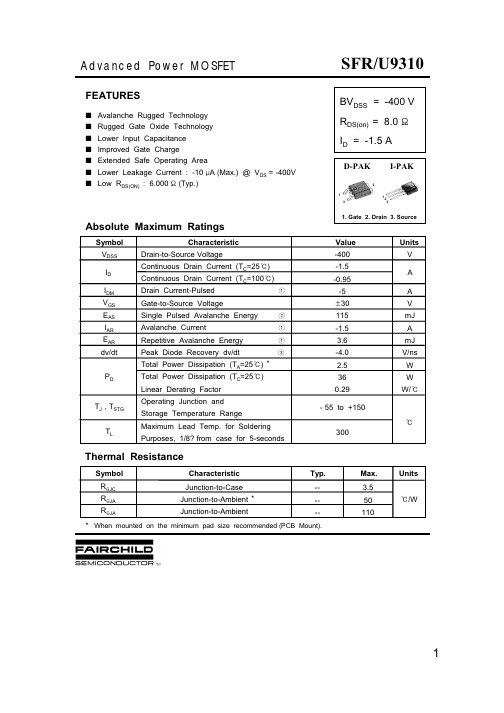
1©2000 Fairchild Semiconductor International TRADEMARKSThe following are registered and unregistered trademarks Fairchild Semiconductor owns or is authorized to use and is not intended to be an exhaustive list of all such trademarks.ACEx™Bottomless™CoolFET™CROSSVOLT™DOME™E 2CMOS™EnSigna™FACT™FACT Quiet Series™FAST ®FASTr™GlobalOptoisolator™GTO™HiSeC™ISOPLANAR™MICROWIRE™OPTOLOGIC™OPTOPLANAR™POP™PowerTrench ®QFET™QS™QT Optoelectronics™Quiet Series™SuperSOT™-3SuperSOT™-6SuperSOT™-8SyncFET™TinyLogic™UHC™DISCLAIMERFAIRCHILD SEMICONDUCTOR RESERVES THE RIGHT TO MAKE CHANGES WITHOUT FURTHER NOTICE TO ANY PRODUCTS HEREIN TO IMPROVE RELIABILITY, FUNCTION OR DESIGN. FAIRCHILD DOES NOT ASSUME ANY LIABILITY ARISING OUT OF THE APPLICATION OR USE OF ANY PRODUCT OR CIRCUIT DESCRIBED HEREIN;NEITHER DOES IT CONVEY ANY LICENSE UNDER ITS PATENT RIGHTS, NOR THE RIGHTS OF OTHERS.LIFE SUPPORT POLICYFAIRCHILD’S PRODUCTS ARE NOT AUTHORIZED FOR USE AS CRITICAL COMPONENTS IN LIFE SUPPORT DEVICES OR SYSTEMS WITHOUT THE EXPRESS WRITTEN APPROVAL OF FAIRCHILD SEMICONDUCTOR INTERNATIONAL.As used herein:1. Life support devices or systems are devices or systems which, (a) are intended for surgical implant into the body,or (b) support or sustain life, or (c) whose failure to perform when properly used in accordance with instructions for use provided in the labeling, can be reasonably expected to result in significant injury to the user.2. A critical component is any component of a life support device or system whose failure to perform can be reasonably expected to cause the failure of the life support device or system, or to affect its safety or effectiveness.PRODUCT STATUS DEFINITIONS Definition of TermsDatasheet Identification Product Status DefinitionAdvance InformationFormative or In Design This datasheet contains the design specifications for product development. Specifications may change in any manner without notice.PreliminaryFirst ProductionThis datasheet contains preliminary data, andsupplementary data will be published at a later date.Fairchild Semiconductor reserves the right to make changes at any time without notice in order to improve design.No Identification Needed Full ProductionThis datasheet contains final specifications. Fairchild Semiconductor reserves the right to make changes at any time without notice in order to improve design.Obsolete Not In ProductionThis datasheet contains specifications on a product that has been discontinued by Fairchild semiconductor.The datasheet is printed for reference information only.Rev. F1VCX™。
NLB-T3
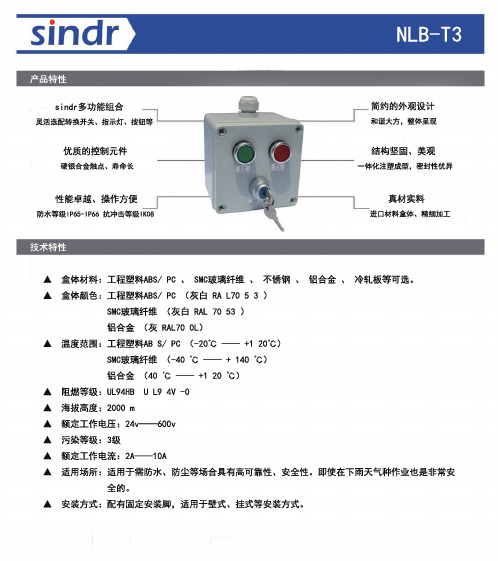
s i n d r 多功能组合
灵活选配转换开关、指示灯、按钮等 优质的控制元件
硬银合金触点、寿命长 性能卓越、操作方便
防水等级I P 65-I P 66 抗冲击等级I K 08 结构坚固、美观一体化注塑成型,密封性优异
真材实料进口材料盒体、精细加工简约的外观设计和谐大方,整体呈现
▲ 盒体材料:工程塑料A B S / P C 、 S M C 玻璃纤维 、 不锈钢 、 铝合金 、 冷轧板等可选。
▲ 盒体颜色:工程塑料A B S / P C (灰白 R A L 70 5 3 )
S M C 玻璃纤维 (灰白 R A L 70 53 )
铝合金 (灰 R A L 70 0L )
▲ 温度范围:工程塑料A B S / P C (-20℃ —— +1 20℃)
S M C 玻璃纤维 (-40 ℃ —— + 140 ℃)
铝合金 (40 ℃ —— +1 20 ℃)
▲ 阻燃等级:U L 94H B U L 9 4V -0
▲ 海拔高度:2000 m
▲ 额定工作电压:24v ——600v
▲ 污染等级:3级
▲ 额定工作电流:2A ——10A
▲ 适用场所:适用于需防水、防尘等场合具有高可靠性、安全性。
即使在下雨天气种作业也是非常安 全的。
▲ 安装方式:配有固定安装脚,适用于壁式、挂式等安装方式。
产品特性技术特性
N L B -T 3。
DCS-931L Quick Install Guide

DCS-931LCloud Camera 1050Wireless N Network CameraPackage ContentsIf any of the above items are missing, please contact your reseller.Minimum RequirementsDCS-931L Cloud Camera 1050Power AdapterCAT5 Ethernet CableQuick Install GuideComputer with:Web Browser• PC with 1.3GHz or above and at least 128MB RAM • Windows® 8, Windows® 7, Vista® or XP (32-bit or 64-bit)• Mac OS® X 10.6 or higher• Internet Explorer® 7, Firefox, Safari 4, or Chrome • Installed and enabled Java and ActiveX® controls• A router (D-Link Cloud Router is recommended)• An Internet connection• An e-mail account (Required to register mydlink service)Network Device and Servicemydlink cloud serviceiPodSmartphonemydlink appWhat is the mydlink™ Service?With a mydlink service enabled camera, you can stay connected to everything you love from anywhere, anytime. The mydlink service can be accessed by a web browser and also provides an optional downloadable mydlink app that allows users to have a better experience on their mobile devices. With the mydlink app, you can quickly and easily view your camera feed from anywhere using a Wi-Fi, 3G or 4G connection.via Smartphone - mydlink Lite App (Free)Search for the words “mydlink lite” to download and install the app on your smartphone or tablet when connected to the Internet. You can also find the app by scanning the QR code below with a QR code scan app.via Tablet - mydlink+ App (Paid)Search for the word “mydlink+” to download and install the app on yourtablet when connected to the Internet. You can also find the app by scanning the QR code below with a QR code scan app.System Requirements: iOS version 4.3 or above. Android version 2.1 or above.System Requirements: iOS version 4.3 or above. Android version 2.1 or above.If you have a D-Link Cloud Router with an Internet connection, you can take advantage of Zero Configuration. This feature automatically configures your camera’s settings for you and adds it to your mydlink account automatically. If you do not have a D-Link Cloud router, refer to the next page to install andIf you wish to connect your camera to your router wirelessly, you can simply disconnect the Ethernet cable and move the camera to its intended location.Zero Configuration Setupto add the camera to your account.Please download the Setup Wizard from /support.Setup WizardIf you do not have a D-Link Cloud Router, you can use any Windows or Mac computer to go through the Setup Wizard, which will guide you through the installation process from connecting your hardware to configuring your camera.Windows Users - Extract (“unzip”) the files to a folder on your computer and then double-click the SETUP_WIZARD.exe file in the Advanced folder.Mac Users - Download the Mac OS Setup Utility. Open the SetupWizard file and launch the application.After about 20-30 seconds, the Setup Wizard will open, which will guide you step-by-step through the installation process from connecting your hardware to configuring your camera and registering it with your mydlink account.Start mydlinkOpen a web browser on any computer connected to the Internet.Enter in the address bar and press Enter .Sign in with your mydlink account registered in the Setup Wizard.123• Windows does not have Java installed by default. Please download it from .• In Mac OS X 10.7.x, Java applets are disabled by default. Click the Finder>Applications > Utilities > Java Preferences and check the Enable applet plug-in and Web Start applications option.• The ActiveX® controls in IE will install automatically if needed. We suggest that you make sure that you have enabled the related options in Tools > Internet Options > Security > Custom Level .Browser Requirements: Java Active X5Camera Use Without mydlink ServiceYou might have some limitations without using the mydink service:• Not be able to manage many devices with a single account.• Need a static IP address or DDNS account to access the camera remotely.• Need several steps to manually setup remote access to the camera behind a router.• Not be able to view the image and modify the settings at the same time on mobile devices.If you do not want to use the mydlink service now, run the Setup Wizard andchoose the option “I don’t want to enable...”. You can run the Setup Wizard again when you want to enable the mydlink service in the future. Check below if your camera behind a router or firewall.Log in the router’s setup page and add rules in the Virtual Server or Port Forwarding sections by entering camera’s IP address and service ports. Then you can use the router’s Internet (WAN) IP address and camera’s HTTP port to access the camera remotely.Configuring the camera behind a RouterTo log in the camera’s setup page, go to SETUP > Network Setup, select “Static IP Address ” and assign an IP address to the camera. The IP address must be in the same subnet mask of the router’s LAN IP .The camera’s default IP address is 192.168.0.20.this page. Leave the other settings to the defaultD-ViewCam enables centralized management of multiple network cameras, supporting up to 32 network cameras and up to 64 users. With a dedicated computer it offers digital monitoring and recording with a wide array of features, including scheduled, motion and manual recording options for individual needs. Download D-ViewCam at /support . Select your camera and select “D-ViewCam” under Wizard .D-L ink provides a software (D-ViewCam) or a hardware (NVRs) solution for advanced users to choose from to manage their cameras and record videos. Depending on the users needs, one or the other solution can be used to supplement their camera system.Network V ideo Recorders (NVRs) are standalone storage devices with a powerful embedded system that can record video from up to 9 network cameras located on local or remote sites into a dedicated HDD storage without turning on a PC. Video and camera management can be done as needed using any computer attached to the network.D-ViewCam™ and Network Video RecordersNVRInternetMobile DeviceLaptopCloud CameraInternetMobile DeviceLaptopNotesNotesTechnical SupportThis guide is only for the first time configuration. Please refer to the user manual to learn more or visit for more information. Also feel free to contact us. U.S. and Canadian customers can contact D-Link Technical Support through our website or by phone.877-453-5465USAhttp://support.dlink.ca800-361-5265CanadaVersion 1.0January 14, 2013Copyright ©2013 All rights reserved. D-Link and the D-Link logo are registered trademarks of D-Link Corporation or its subsidiaries. Other trademarks are the property of their respective owners. Maximum wireless signal rate derived from IEEE Standard 802.11g and 802.11n specifications. Actual data throughput will vary. Network conditions and environmental factors, including volume of network traffic, building materials and construction, and network overhead, lower actual data throughput rate. Environmental factors will adversely affect wireless signal range. Product specifications, size and shape are subject to change without notice, and actual product appearance may differ from that depicted on the packaging. Visit (US) or dlink.ca (Canada) for more details.。
- 1、下载文档前请自行甄别文档内容的完整性,平台不提供额外的编辑、内容补充、找答案等附加服务。
- 2、"仅部分预览"的文档,不可在线预览部分如存在完整性等问题,可反馈申请退款(可完整预览的文档不适用该条件!)。
- 3、如文档侵犯您的权益,请联系客服反馈,我们会尽快为您处理(人工客服工作时间:9:00-18:30)。
UTC assumes no responsibility for equipment failures that result from using products at values that exceed, even momentarily, rated values (such as maximum ratings, operating condition ranges, or other parameters) listed in products specifications of any and all UTC products described or contained herein. UTC products are not designed for use in life support appliances, devices or systems where malfunction of these products can be reasonably expected to result in personal injury. Reproduction in whole or in part is prohibited without the prior written consent of the copyright owner. The information presented in this document does not form part of any quotation or contract, is believed to be accurate and reliable and may be changed without notice.
1 of 2
QW-R214-015,A
元器件交易网
BU931Z
ABSOLUTE MAXIMUM RATINGS (Ta=25 )
PARAMETER Collector-Emitter Voltage Emitter-Base Voltage Collector Current (DC) Collector Peak Current Base Current Base Peak Current Total Dissipation (Tc = 25 ) Junction Temperature Storage Temperature SYMBOL BVCEO BVEBO IC ICM IB IBM PD TJ TSTG
BU931L-T3P-T
(1)Packing Type (2)Package Type (3)Lead Plating
(1) T: Tube (2) T3P: TO-3P (3) L: Lead Free Plating, Blank: Pb/Sn
Copyright © 2007 Unisonic Technologies Co., Ltd
NPN SILICON TRANSISTOR
1 TO-3P
INTERNAL SCHEMATIC DIAGRAM
C B (1) (2)
*Pb-free plating product number: BU931L
E
(3)
ORDERING INFORMATION
Ordering Number Normal Lead Free Plating BU931-T3P-T BU931L-T3P-T Package TO-3P Pin Assignment 1 2 3 B C E Packing Tube
NPN SILICON TRANSISTOR
RATINGS 350 5 10 15 1 5 125 +175 -65 ~ +175
UNIT V V A A A A W
ELECTRICAL CHARACTERISTICS
PARAMETER Collector Cut-off Current Emitter Cut-off Current Collector-Emitter Saturation Voltage Base-Emitter Saturation Voltage DC Current Gain Diode Forward Voltage Inductive Load Storage Time / Fall Time tF SYMBOL ICEO IEBO VCL VCE(SAT)1 VCE(SAT)2 VBE(SAT)1 VBE(SAT)2 hFE VF tS TEST CONDITIONS VCE = 300 V VEB = 5 V IC = 100mA IC = 7 A, IB = 70 mA IC = 8 A, IB = 100 mA IC = 7 A, IB = 70 mA IC = 8 A, IB = 100 mA VCE = 10 V, IC = 5 A IF = 8 A VCC = 12 V, Vclamp = 300 V L = 7 mH IC = 7 A, IB = 70 mA VBE = 0, RBE = 47Ω MIN TYP MAX UNIT 100 µA 20 mA 500 V 1.6 V 1.8 V 2.2 V 2.4 V 2.5 15 0.5 V µs µs
350
300
Note: 1. Wafer area should be than 50% 2.The quantity of cracked wafers should be less than 10% per shipment. 3.Auerage yield should be more than 50% per wafer, 80% per shipment.
UNISONIC TECHNOLOGf 2
QW-R214-015,A
元器件交易网
UNISONIC TECHNOLOGIES CO., LTD BU931Z
NPN POWER DARLINGTON
FEATURES
* High operating junction temperature * High voltage ignition coil driver * Very rugged bipolar technology