1808CC100ZA13A中文资料
罗密C系列重型CNC纵轴机头产品说明书

ROMI C SERIESHEAVY DUTY CNC LATHESROMI Industrial Complex, in Santa Bárbara d’Oeste - SP, BrazilROMI: Producing high quality technology since 1930.Since the beginning, Romi has been recognized for its focus on creating products and innovative solutions which has guaranteed its technological leadership among large manufacturers of machine tools. Romi’s industrial complex is among the most modern and productive sites in the fields of machine tools, plastic processing machines, and high quality cast iron parts.Continuous investments in Research & Development result in products with state-of-the-art technology.The technology applied to Romi machines offers highly reliable products, with high accuracy, efficiency and great flexibility for several types of machining processes.Romi R&D is focused on increasing competitiveness for its customers. Present throughout Brazil and in over 60 countries.Romi covers all domestic territory through its sale subsidiaries network fully prepared to support customers by supplying an extensive range of services from marketing to after sales assistance.The international market is covered by Romi’s subsidiaries which are located in the United States, Mexico, Europe, and by its many dealers located in strategic logistic centers around the globe that are capable of serving customers in 5 continents.23Flexibility for several levels of application with assured productivity.CNC lathes from ROMI C Series are machines with great flexibility for machining several types of parts, with great level of power, quick movements and machining accuracy.They are targeted on oil & gas, suggar mill, naval, steel mills and energy segments of heavy industries. Robust structure with monoblock cast iron bed and outlets for chips and coolant fluid.| ROMI C 1100H | ROMI C 1290H | ROMI C 1300H | ROMI C 1300HBB | ROMI C 1600H | ROMI C 1800H | ROMI C 2100H | ROMI C 2200H | ROMI C 2600H•Headstock ASA A2-20”•Spindle thru-hole: Ø 375 mm (14.8)•Swing over bed: 1,110 mm (44”) (ROMI C 1100H)1,330 mm (52”) (ROMI C 1290H)•Main motor: 72 hp / 53 kW•T ailstock with motorized displacement, manual driven quill withbuilt-in live center and compensation by plate springs with monitoringsystem by load sensors of the thrust force and manual lubrication•CNC Siemens 840D with high performance and reliability ROMI C 1100H / C 1290H45• Headstock ASA A2-20”, Ø 305 mm (12”) thru-hole• Headstock Flat Nose, Ø 575 mm (23”) thru-hole (ROMI C 1300HBB - Big Bore)• Swing over bed: 1,300 mm (51”) (ROMI C 1300H / C 1300HBB) 1,600 mm (63”) (ROMI C 1600H) • Main motor (30 min. rating): 114 hp / 84 kW • Tailstock with motorized displacement, manual driven quill with built-in live center and compensation by plate springs with monitoring system by load sensors of the thrust force • CNC Siemens 840D with high performance and reliability ROMI C 1300H / C 1600H / C 1300HBB6ROMI C 1800H / C 2100H• Headstock ASA A2-20”, Ø 305 mm (12”) thru-hole • Swing over bed: 1,800 mm (71”) (ROMI C 1800H)2,150 mm (85”) (ROMI C 2100H)• Main motor (30 min. rating): 114 hp / 84 kW• Tailstock with motorized displacement, manual driven quill with built-in live center and compensation by plate springs with monitoring system by load sensors of the thrust force • CNC Siemens 840D with high performance and reliability7ROMI C 2200H / C 2600H• Headstock ASA A2-20”, Ø 305 mm (12”) thru-hole • Swing over bed: 2,100 mm (83”) (ROMI C 2200H)2,580 mm (102”) (ROMI C 2600H)• Main motor (30 min. rating): 155 hp / 114 kW• Tailstock with motorized displacement, manual driven quill with built-in live center and compensation by plate springs with monitoring system by load sensors of the thrust force • CNC Siemens 840D with high performance and reliabilityROMI C 1100Hbed.BEDRobust monoblock bed made of gray cast iron. Offers great rigidity,absorbing high machining efforts and vibration, assuring stabilityand accuracy at full power operation. The bed is a base forcomponents supporting and it is fixed on the foundation by levellingand alignment elements.GuidesThey constitute a self-adjusting system, assuring permanent contactof cross slide over the bed.ROMI C 1300H Bed machining89ROMI C 2200H Bed machiningROMI C 2200H bedCast iron robust housing, internally ribbed to absorb high efforts of heavy machining operations. Spindle is held by Timken precision bearings. The high loading capacity of bearings provides rigidity and high vibration absorption under the most severe cutting conditions, obtaining parts with excellent geometric accuracy.It is powered by AC motor by pulleys and poly-V belt, with high torque and continuously variable speeds.Headstock lubrication systemEnsures that all components of the headstock are constantly lubricated with an ideal working temperature. The system has an air / oil heat exchanger with thermostat to ensure temperatures lower than 40 degrees. It has dosage system and digital flow sensors, beyond of magnetic elements and suction filter, in order to protect bearings and pump gears against the contamination with particles.ROMI C 1100H / C 1290HGears from the headstock transmission system with hardenedand ground teeth, designed to withstand the high efforts of themost severe working conditions.1011TAILSTOCKThe manually driven quill has a built-in live center with high precision bearings. It has a monitoring system by load sensors of the thrust force. Its displacement is driven by gearmotor and pinion/rack system.Tailstock displacement systemTailstock - ROMI C 2200H / C 2600H, with plataform for operator.Offers high load capacity, rigidity and vibration absorption.ROMI C 1100H / C 1290H TailstockLongitudinal saddleDriven by servo motor through a pre-loaded double pinion system(Redex) that operates on the bed precision racks (Güdel), withpositioning reading through linear scale (Heidenhain) (ROMI C 1800H /ROMI C 2100H / ROMI C 2200H / ROMI C 2600H / and ROMI C 1300H/ ROMI C 1600H from 6.5 to 12.5 m (256” to 492”) between centers).Driven by servo motor through precision recirculating ball screw(ROMI C 1300H / ROMI C 1600H with 3.5 m (138”) and 5 m (197”)between centers). It has guideways with low friction coefficient material that offers high sliding performance (ROMI C 1100H / C 1290H / C1300H / C 1600H / C 1300HBB; and ROMI C 1800H / C 2100H / C 2200H / C 2600H with bronze coating).1213RESTSSteady rest C type (optional)T able rest (optional)Equipped with rollers and manual diameter adjustment.It has a drag system via longitudinal saddle for its positioning.Steady rest U type (optional)It has 5 cartridges with rollers for diameter adjustment. The steady rest bodydisplacement is done by the longitudinal saddle.144 - station square manual turret4 - station square vertical turret, electrically drivenElectrical turret for driven tools with Y axis (optional)12 station tool disk VDI-60 for driven tools, 10 hp (7.5 kW) 2,500 rpm (max.).TURRETSTurrets (optionals)The heavy duty CNC lathes ROMI C Series are equipped with different robust turrets for several types of applications.BORING BARMilling Headstock with Y axis (optional) Spindle taper ISO-50, 16 hp / 12 kW, 2,500 rpm (max.)Milling Headstock (optional)Spindle taper ISO-50, 10 hp / 7.5 kW, 2,500 rpm (max.)Boring bar holderSystem with double support for thebar. Its robust structure offers highrigidity and vibration absorptionduring machining operations at fullpower.1516PLATFORMC axis (optional)Mechanical system withindependent servomotor, which is coupled to the machine spindle. Allows positioning the spindle at any angle, as well as perform interpolation operations in machining processes.PlatformCNC lathes ROMI C 1800H / ROMI C 2100H / ROMI C 2200H and ROMI C 2600H have aplatform for the operator, providing easy access to the operator‘s panel, turret workpiece and also for other machine setup operations. In order to guarantee operator safety, the platform is equipped with front cover, door viewer protection and electric locks.CNCTechnology, high performance and reliabilityCNC horizontal lathes from ROMI C Series are equipped with CNC Siemens Sinumerik 840D which,offers the user very ease programming system.CNC Siemens Sinumerik 840D offers 21.5” touch screen monitor, USB port and Ethernet interface for factory network, bringinga great flexibility for loading programs and parameters.Conversational programming offered is the programGUIDE CNC Siemens Sinumerik 840D programGUIDE facilitates programcreation thru the input of data in user-friendly screens and animated elements which helps in unequivocal data input. Programming is simplified thru cycles of drilling, boring, tapping and milling cycles and free-shape profile cuts.TOUCHSCREEN17(*) Other characteristics like distance between centers, maximum admissible weight beetween centers, power and rotation can be offered under request (**) Weight increase for each 1,500 mm (59”) bed segment = 2,500 kg (5,500 lbs) (ROMI C 1100H / C 1290H) Weight increase for each 1,500 mm (59”) bed segment = 2,500 kg (5,500 lbs) (ROMI C 1300H / C 1600H) Weight increase for each 1,500 mm (59”) bed segment = 4,000 kg (8,800 lbs) (ROMI C 1800H / C 2100H) Weight increase for each 2,000 mm (79”) bed segment = 6,000 kg (13,200 lbs) (ROMI C 2200H / C 2600H)1819• Articulated and sliding operationpanel (except ROMI C 1100H / C1290H)• Centralized lubrication system with line filter oil and level sensor (PDI)• Chip conveyor interface (except ROMI C 1100H / C 1290H)• Coolant system with motor pump 10 l/min, 2 bar, 0.75hp / 0.56kW (ROMI C 1300H / C 1600H / C 1800H / C 2100H / C 2200H / C 2600H)• Coolant system with two coolant pumps for choice 2 bar or 7 bar (ROMI C 1100H / 1290H)• 12-station horizontal electrical turret, VDI-60 for driven tools (tool holders and reduction sleeves not included) (ROMI C 1600H)• 3-jaw independent chuck, cast iron ASA A2-20” (flange not included): - Ø 630 mm, thru-hole Ø 252 mm (max. 500 rpm) ROMI C 1100H / 1290H - Ø 800 mm, thru-hole Ø 320 mm (max. 300 rpm) ROMI C 1100H / 1290H - Flange for 3-jaw universal chuck A2-20” Ø 630 ou Ø 800 mm• 4 jaw independent rear chuck steel body ASA A2-20”:- Ø 720 mm, thru-hole Ø 375 mm (max. 873 rpm) ROMI C 1100H• 4-jaw independent chuck, steel body ASA A2-20”:- Ø 700 mm (max. 873rpm) ROMI C 1100H / 1290H- Ø 720 mm, thru-hole Ø 375 mm (max. 873rpm) ROMI C 1100H / 1290H - Ø 800 mm (max. 764 rpm) ROMI C 1100H / 1290H / 1300H / 1600H / 1800H- Ø 900 mm (max. 679 rpm) ROMI C 1100H / 1290H- Ø 1000 mm (max. 611 rpm)ROMI C 1100H / 1290H / 1300H / 1600H / 1800H / 2100H / 2200H / 2600H- Ø 1100 mm (max. 509 rpm) ROMI C 1290H - Ø 1200 mm (max. 509 rpm) ROMI C 1300H / 1600H / 1800H / 2100H / 2200H / 2600H - Ø 1400 mm (max. 437 rpm) ROMI C 1800H / 2100H / 2200H / 2600H• Electrical installation for 380 V or 400V 50 / 60 Hz• Electrical panel with air conditionin g (except ROMI C 1100H / 1290H)• Ethernet interface • Fluorescent worklight• Geared headstock, with two speed ranges and continuous speed variation • Headstock coolant and lubrication system equipped with heat exchanger, sensors for temperature, pressure, flow and filter- Ø 1500 mm (max. 407 rpm) ROMI C 1300H / 1600H / 1800H / 2100H / 2200H / 2600H - Ø 1600 mm (max. 382 rpm)ROMI C 1800H / 2100H / 2200H / 2600H - Ø 1800 mm (max. 340 rpm) ROMI C 1800H / 2100H / 2200H / 2600H- Ø 2000 mm (max. 306 rpm) ROMI C 2200H / 2600H• 4-station square manual turret• 4-station vertical electrical turret (tool holders and reduction sleeves not included)• 8-station horizontal electrical turret for driven tools, VDI-50 (DIN 69880) (toolholders and reduction sleeves not included) (ROMI C 1100H / C 1290H)• 8-station horizontal electrical turret for driven tools, VDI-50 (DIN 69880) (tool holders and reduction sleeves not included)• 8-station horizontal electrical turret, VDI-50 (DIN 69880) (tool holders and reduction sleeves not included)• Air conditioning for electrical panel (recommended for environments with temperature higher than 38°C) (ROMI C 1100H / C 1290H)• Autotransformer for 200 to 250 VCA or 360 to 480 VCA, 50/60 Hz• Deep hole drilling support (bar not included): - Ø 160 mm (ROMI C 1100H / 1290H)- Ø 200 mm fixed over cross slide, with 3rd guide (ROMI C 1300H / 1600H)• Remote operation panel withhandwheel and JOG functions for axes • Set of anchor, screws and nuts for leveling and alignment • Set of instruction manuals• Set of wrenches for machine operation • CNC Siemens 840D, with 21.5” touch screen monitor• Splash guard with sliding doors • Standard colors: Textured epoxy enamel munsell blue 10B-3/4 and textured epoxy gray RAL 7035- Ø 200 mm fixed in square manual turret with vertical axis, with 3rd guide (ROMI C 1300H / C 1600H)- Ø 250 mm fixed over cross slide, with 3rd guide (ROMI C 1800H / 2100H / 2200H / 2600H)- Ø 250 mm fixed in square manual turret with vertical axis, with 3rd guide (ROMI C 1800H / 2100H / 2200H / 2600H)• C axis driven by independent servomotor and hydraulic brake• Chip conveyor hinged belt longitudinal (TCE)• Chip pan and coolant tank• Generic interface with miscellaneous functions (4 M codes)• Linear scale for Z axis• Main spindle indexing with 72 position (5 degrees) - ASA A2-20”• Oil Skimmer• Special painting according to Munsell or RAL Standards• Steady rest C type, with capacity: - Ø 300 to 800 mm (ROMI C 2600H)• Steady rest U type, with capacity: - Ø 230 to 550 mm (ROMI C 1100H) - Ø 200 to 635 mm (ROMI C 1290H)- Ø 230 to 600 mm (ROMI C 1300H / 1600H / 1300HBB)- Ø 380 to 750 mm (ROMI C 1600H)• Tailstock with manually operated quill, built-in center with plate springs compensation and supervision of applied force and lubrication • Pivoted operation panel (ROMI C 1100H / C 1290H )- Ø 275 to 800 mm (ROMI C 1800H / 2100H) - Ø 300 to 800 mm (ROMI C 2200H / 2600H)• Steady table rest, with capacity: - Ø 340 to 720 mm (ROMI C 1100H) - Ø 300 to 950 mm (ROMI C 1290H) - Ø 500 to 900 mm (ROMI C 1300H / C 1300HBB)- Ø 500 to 1,200 mm (ROMI C 1600H) - Ø 750 to 1,200 mm (ROMI C 1800H) - Ø 800 to 1,600 mm (ROMI C 2100H) - Ø 800 to 1,550 mm (ROMI C 2200H) - Ø 800 to 2,000 mm (ROMI C 2600H)• Table rest• Tailstock with hydraulically driven quill, built-in live center and displacement through carriage in place of standard • Y axis• Remote diagnosis interfaceNote: Other optional equipments under request.Drawings are not in scale.CE safety regulation compliance available only for the European Community or under request.Check availability and technical characteristics of the products to your country.ROMI BW Machine Tools Ltd 1845 Airport Exchange Blvd Erlanger KY – 41018 USA +1 (859) 647 7566*****************ROMI Itália SrlVia Morigi, 33 – 29020Gossolengo (PC) – Italy +39 0523 778 956*************************www.romiitalia.itBurkhardt+WeberFertigungssysteme GmbH Burkhardt+Weber-Strasse 5772760 Reutlingen, Germany + 49 7121 315-0***********************www.burkhardt-weber.deROMI Europa GmbHBurkhardt+Weber-Strasse 5772760 Reutlingen, Germany + 49 7121 315-604********************www.romi-europa.deROMI France SAS Parc de Genève, 240Rue Ferdinand Perrier 69800ST Priest+33 4 37 25 60 70*******************www.romifrance.fr ROMI Machines UK Limited Leigh RoadSwift Valley Industrial Estate Rugby CV21 1DS +44 1788 544221****************ROMI Maquinas España C/ Telemática, 9 - Poligono Industrial La Ferreria - 08110 Montcada I Reixac - Barcelona +34 93 719 4926************www.romi.esROMI en MéxicoCondominio Parque Arista, Calle Gral. Mariano Arista 54, bodega 19Col. Argentina Poniente, Miguel Hidalgo C.O. 11230, CDMX, México +521 55 9154 5851***************** ROMI S.A.Rod. SP 304, Km 141,5Santa Bárbara d’Oeste SP 13459 057 Brazil +55 (19) 3455 9000Latin America +55 (19) 3455 9642******************W W W.R O M I.C OMMexico Brazil United States Germany England FranceSpain ItalyGermany - B+WR O M I C S E R I E S / I N / A P / 092022 - I l l u s t r a t i v e p h o t o s - S p e c i f i c a t i o n s a r e s u b j e c t t o c h a n g e w i t h o u t p r i o r n o t i c e - P l e a s e r e c y c l e .。
DS-K1808A 系列读卡器 用户手册说明书

DS-K1808A系列读卡器用户手册法律声明版权所有©杭州海康威视数字技术股份有限公司2020。
保留一切权利。
本手册的任何部分,包括文字、图片、图形等均归属于杭州海康威视数字技术股份有限公司或其关联公司(以下简称“海康威视”)。
未经书面许可,任何单位或个人不得以任何方式摘录、复制、翻译、修改本手册的全部或部分。
除非另有约定,海康威视不对本手册提供任何明示或默示的声明或保证。
关于本产品本手册描述的产品仅供中国大陆地区销售和使用。
本产品只能在购买地所在国家或地区享受售后服务及维保方案。
关于本手册本手册仅作为相关产品的指导说明,可能与实际产品存在差异,请以实物为准。
因产品版本升级或其他需要,海康威视可能对本手册进行更新,如您需要最新版手册,请您登录海康威视官网查阅( )。
海康威视建议您在专业人员的指导下使用本手册。
商标声明• 为海康威视的注册商标。
•本手册涉及的其他商标由其所有人各自拥有。
责任声明•在法律允许的最大范围内,本手册以及所描述的产品(包含其硬件、软件、固件等)均“按照现状”提供,可能存在瑕疵或错误。
海康威视不提供任何形式的明示或默示保证,包括但不限于适销性、质量满意度、适合特定目的等保证;亦不对使用本手册或使用海康威视产品导致的任何特殊、附带、偶然或间接的损害进行赔偿,包括但不限于商业利润损失、系统故障、数据或文档丢失产生的损失。
•您知悉互联网的开放性特点,您将产品接入互联网可能存在网络攻击、黑客攻击、病毒感染等风险,海康威视不对因此造成的产品工作异常、信息泄露等问题承担责任,但海康威视将及时为您提供产品相关技术支持。
•使用本产品时,请您严格遵循适用的法律法规,避免侵犯第三方权利,包括但不限于公开权、知识产权、数据权利或其他隐私权。
您亦不得将本产品用于大规模杀伤性武器、生化武器、核爆炸或任何不安全的核能利用或侵犯人权的用途。
•如本手册内容与适用的法律相冲突,则以法律规定为准。
数据安全声明•您在使用产品的过程中,将收集、存储与使用个人数据。
SC1088中文资料
Pin No. 9 10 11 12 13 14 15
Symbol ViIF CLP2 VIRF VIRF CLIM GND CAP
16
TUNE
Description IF input to limiter amplifier Low-pass capacitor of IF limiter amplifier Radio frequency input Radio frequency input Limiter offset voltage capacitor Ground All-pass filter capacitor.input for search tuning
HANGZHOU SILAN MICROELECTRONICS JOINT-STOCK CO.,LTD
5
元器件交易网
Silan Semiconductors
HANGZHOU SILAN MICROELECTRONICS JOINT-STOCK CO.,LTD
Tamb=25°C,Vp=3V,Firf=96MHz modulated with ∆f=±22.5kHz and fm=1kHz deviation;EMF=0.3mV(e.m.f. at a
sourse impedance of 75Ω),and measurement taken in fig.3 Unless otherwise specified
元器件交易网
Silan Semiconductors
SC1088
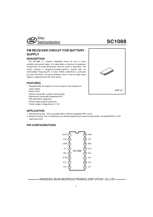
FM RECEIVER CIRCUIT FOR BATTERY SUPPLY
DESCRIPTION
The SC1088 is a bipolar integrated circuit for use in mono portable and pocket radios. It is used when a minimum of perpheral components (of small dimensions and low costs) is important. The circuit contains a frequency-locked-loop(FLL) system with an intermediate frequency(IF) of about 70kHz. Selectivity is achieved by active RC-filters. De-tuning related to the IF and too weak input signal is suppressed by the mute circuit.
Pacific Power Source ASX系列高密度AC测试单相和三相切换AC电源说明书
ASX SeriesHigh-Density AC T est PowerSingle and Three Phase Switchmode AC Power SourcesT h e P o w e r o f E x p e r t i s eModels from 1,500 VA to 12,000 VAAdvanced Test Equipment Rentals 800-404-ATEC (2832)E s t a b l i s h e d 1981ASX Series AC Power SourcesThe ASX Series is Pacific Power Source’s family of High Performance AC Power Sources ranging from 1.5kVA to 12kVA. Power conversion within the ASX Series is achieved by high frequency pulse width modulation, resulting in cool, quiet, andefficient operation.ApplicationsAC Test PowerThe ASX Series Power Source is equipped with a powerful microcontroller to create a fully integrated test system. It supplies a variety of power conditions to the device under test and meters/analyzes all output performance parameters.Frequency/Voltage ConversionThe ASX Series is an excellent source of stable AC voltage over the frequency range of 15 to 1,200 Hz. The output frequency is quartz-crystal stabilized. Output voltages up to 600 VAC are provided.Phase ConversionWith the ability to provide single and three-phase outputs, the ASX Series is the perfect choice to provide 1 Phase to 3 Phase or 3 Phase to 1 Phase conversion.Standard Features of each system include:• 22 Waveform Library – Arbitrary Waveform Generator.• 15 to 1,200 Hz Operation – 5,000 Hz Bandwidth.• Precision Voltage Programming – 0.05% with Continuous Self-Calibration (CSC) engaged.• Precision True-RMS metering of volts, amps, and power for displays and reporting.• RS-232 Interface with SCPI.• 1 Phase/3 Phase Switch Selectable Output from front panel or bus command.• 99 stored programs for both static and dynamic Transient Testing.Available options of each system include:• GPIB (IEEE-488.2) Interface with SCPI.• Programmable Output Impedance.• Harmonic Analysis (FFT) and Waveform Synthesis.• Load Surge Analysis and Waveform Capture.• LabView for Windows™and LabWindows™Instrument Drivers.• UPC Manager Compiled Software Suite.• Wide range of Output Magnetics for world-wide testing.Other controllers are available for applications where the ASX Serieswould be used as a manually controlled laboratory instrument, or afixed parameter OEM frequency converter.Controller Selection GuideFour controller models are available with the ASX-Series. They include 1 Phase and 3 Phase models for both manual and programmable control.• UPC-1M 1 Phase Manual Control15 Hz to 1,200 Hz.• UPC-3M 3 Phase Manual Control15 Hz to 1,200 Hz.• UPC-1 1 Phase Programmable Control15 Hz to 1,200 Hz.• UPC-3 3 Phase Programmable Control15 Hz to 1,200 Hz.All controllers provide manual operation from the front panel. Programmable Controllers may be programmed from the front panel or from a remote interface. RS-232 Interface is standard. IEEE-488 interface is optional. Programmable Output Impedance (optional)This feature creates positive, negative, or zero output impedance (Z0).• Compensates for line distribution or transformer losses.• Simulates a soft power line for product testing.Compensation range is ±10% of the output voltage.Transient GenerationTime Based TransientsCreate and execute transients that occur over a specified time segment to modify the output waveform, voltage, and frequency for any or all phases. An output trigger is provided for synchronizing external test equipment to the actual transient event.Cycle Based TransientsCreate and execute transients that substitute a waveform in any or all phases for 1 to 100 cycles. The waveform being substituted can be selected and/or modified from the waveform library.Arbitrary Waveform Generation and AnalysisWaveform EditA full-featured editor permits modification of a stored waveform in both time and frequency domains. This method can be used to quickly create spikes, dropouts, notches and other sub-cycle wave conditions. The resulting modified waveform is stored for execution in steady-state or transient programs.Waveform LibraryUp to 22 different waveforms can be stored in the waveform library for execution as part of a steady state program or for substitution in any output phase as part of a transient test program. Memory location #1 is a noneditable high resolution sine wave. Locations 2-22 are editable and can be substituted in anyoutput phase.Waveform Harmonic Synthesis (optional)Quickly create virtually any AC test waveform by building it out of harmonics. The process is as simple as keying in the magnitude and phase angle of each desired harmonic up through the 51ST. Additionally, waveforms can be created by downloading from a host PC.Waveform Analysis (optional)Provides both graphic (using LabView for Windows™) and numeric displays of the harmonic structure of a voltage or current waveform. Each waveform is analyzed for its harmonic content, up to the 51ST harmonic. Amplitude and phase are reported to the local display. UPC Manager displays numeric values as wellas a graphic summary of the harmonic spectrum.Oscillograph of voltage and currentwaveform at load due todistribution losses. THD=6.6%Same conditions as above withprogrammable Zºengaged.THD=0.25%THD=8.7%THD=22.2%THD=18.1%WAVEFORM EDITWAVEFORM SYNTHESISHARMONIC CONTENT OF METERED WAVEFORMTIME BASED TRANSIENTSCYCLE BASED TRANSIENTSEDIT WAVEFORM: NUMBER=16RANGE=2-16STARTING PHASE ANGLE=0 0-359.5°ENDING PHASE ANGLE=0 0-359.5°VOLTAGE IN PERCENT=-100 (+/-)0-100%WAVEFORM SYNTHESIS: WAVEFORM #2HARMONIC:2nd3rd4th5th6th CONTENT:.1%0%0%0%0%ØANGLE:0°0°0°0°0°V/I METER: ENTRY: 120.0FREQ=60.00 Va=120.0Vb=120.0Vc=120.0 SENSE=INT Vab=208.0Vbc=208.0Vca=208.0 MANUAL MODE Ia=06.00Ib=06.22Ic=06.15POWER METER: PHASE A PHASE B PHASE C KVA0.7200.7460.738 KW0.7200.7460.738 PF 1.000 1.000 1.000AMPS METER: PHASE A PHASE B PHASE CRMS0.7200.7460.738PEAK 1.044 1.119 1.383CREST FACTOR 1.45 1.50 1.90SETUP: PRESS 1 FOR PROGRAM SETUP2 FOR WAVEFORM SETUP3 FOR GENERAL SETUP4 FOR CALIBRATION MENU ØA CURRENT THD=17.8 % OHD=17.8EHD=0.3% HARMONIC:2nd3rd4th5th6th CONTENT:.1%17.8%0%0%0%ØANGLE:0°0°0°0°0°WAVEFORM SYNTHESIS: WAVEFORM #2 HARMONIC:2nd3rd4th5th6th CONTENT:.1%0%0%0%0%ØANGLE:0°0°0°0°0°EDIT WAVEFORM: NUMBER=16RANGE=2-16 STARTING PHASE ANGLE=00-359.5°ENDING PHASE ANGLE=00-359.5°VOLTAGE IN PERCENT=-100(+/-)0-100%Metering Waveform Control/Analysis Function KeyProvides Access to Special FunctionsProgram Setup• Copy a program.• Delete a program.• Erase all memory, reset CPU. Waveform Setup• Edit a waveform.• Copy a waveform.• Waveform synthesis.General Setup• UPC setup.• LCD setup.• UPC status.• Power source status.• Range control.• Slew rate setup.Calibration Menu• Execute externally referenced calibration.• View calibration constants.• Current Protect Opens power source output when operatordefined limits are exceeded.• Sense Establishes either local or remote sense for metering and CSC.• CSC Continuous self calibration – provides for exceptionalvoltage accuracy.• Program Z°Programmable output impedance dynamicallycompensates for output transformer or line distributionlosses. Can simulate a soft power grid.• Transition Time Permits control of the transition time whenchanging the output voltage and frequency.• Frequency Limits Sets min and max programmable frequency limits.• Voltage Limits Sets min and max programmable voltage limits.• Initial Voltage Sets power on voltage as zero volts or last executed.• Keyboard Lock Enable/disable front panel controls.Special Functions AccessedThrough UPC Setup Menu• Soft green backlight.• Adjustable.Informative 160Character LCD DisplayTotal Control, Metering, and Analysis of AC Power. Simple, Intuitive Operation.Select phase voltages and operating frequency when manual control is desired. The selected parameter is indicated by the LCD display. The clear key erases entries and keeps erasing with repeated pressing until the basic V/I screen is displayed.Parameter Select KeysExecute KeyInstantly executes a stored program that has been selected with the program key.Slew KeysSmoothly changethe designated voltage or frequency parameters.Rates are separately programmable.Transient (Trans) KeyTurns time based or cycle based transients On or Off. Indicator is On when transient is executed.Output Enable KeyTurns the output contactor of the power source On or Off. Indicator is On when the contactor is closed.Enter KeyStores new parameter data that has been keyed in.Program KeySelects 1 of 99 programs for edit or execution.Edit KeySelects the program edit mode and prompts for new entry.Store KeyStores a program upon completion of editing.Display KeySequences through each metering screen:• V/I Meter.• Power Meter.• AMPS Meter.• Waveform Analysis (option).ASX Series – Power SourcesNotes:1. Rated output power is based on a combination of output voltage, current and load power factor. Values stated represent the maximum capabilities of a given model. Consult factory for assistance in determining specific unit capabilities as they might apply to your application.2. All single phase output units (Model 115 ASX excepted) are operable with dual voltage ranges as listed. Three phase units are operable as single phase with dual voltage range capability or as three phase. Output voltage ranges and 1Ø/3Ø conversions are selected by front panel or bus commands.3. Output voltage ranges listed are for standard units. VMAX is output voltage with nominal input and full rated load applied. Other voltage ranges are available with the output magnetics options below.4. Peak Repetitive Pulse Current.5. Single phase input: 100, 110, 120, 208, 220, 230 and 240 VAC ±10%. Three phase input: 208, 220, 240, 380 and 416 VAC ± 10%. (480 V input and 400 Hz input are each available as a cost option.)6. Available current will vary with output voltage and power factor.Power Source Specifications(V out > 25% F.S.)Output Frequency 15 to 1,200 Hz. Full Power.Line Regulation 0.1% max for a ±10% line change.Load Regulation0.25% 15 to 400 Hz.(Typ. 3 phase direct coupled)0.50% 400 to 1,200 Hz.Improves to less than 0.1% with external sense and CSC enabled.Output Distortion 0.25% THD AVG 15 to 200 Hz.0.50% THD AVG 200 to 1,200 Hz.Ripple and Noise –66 dBResponse Time60 microseconds typical, 10–90%load step.All models are designed for operation in 19-inch equipment racks. Models 4 kVA and higher have side handles for ease of handling.Mounting Standard 19-inch rack. Slide railsare available as an option for all models.Height See model table above for panel height.Depth Approximately 24-inch, from the front panel to the rear of the chassis.CoolingFront or side forced air intake with rearexhaust. Automatic Fan Speed Control for low acoustic noise and extended fan life.ASX Series Power Sources can be equipped with output transformers to provide an alternate output voltage range. Selection of direct or transformer coupled range is performed by the controller via front panel or bus command. The standard frequency range for transformer coupled outputs is 45 to 1,200 Hz. Standard output ratios are 1.5:1, 2.0:1, and 2.5:1. Transformer outputs are supplied internally or externally via a Magnetics Module as listed in the above table. Consult the factory for additional information regarding special output ranges not listed above.Mechanical SpecificationsDual Range Output Magnetics OptionsMODELRATED P0WER (VA)OUTPUT FORM (Note 2)OUTPUT VOLTS MAX (Note 3)(V RMS )OUTPUT AMPS MAX (Note 6)(A RMS )OUTPUTAMPS (Note 4)(A PK )OUTPUT MAGNETICS INPUT POWER FORM (Note 5)PANEL HEIGHT (IN. + U)WEIGHT (LBS.)115ASX 1,5001Ø1321635INT.1Ø47 to 63 Hz 5¼-3U65120ASX 2,0001Ø150/30020/1490/45N/A 1Ø47 to 63 Hz 5¼-3U 75140ASX 4,0001Ø135/27032/1690/45EXT.3Ø47 to 63 Hz 8¾-5U 120315ASX 1,5001Ø3Ø132/264132 V L-N 12/64/Ø69/2323/ØINT.1Ø47 to 63 Hz 5¼-3U 75320ASX 2,0001Ø3Ø150/300150 V L-N 20/127/Ø69/2323/ØN/A 1Ø47 to 63 Hz 5¼-3U 85345ASX 4,5001Ø3Ø135/270135 V L-N 36/1212/Ø100/4040/ØEXT.3Ø47 to 63 Hz 8¾-5U 145360ASX 6,0001Ø3Ø132/264132 V L-N 48/1616/Ø120/4545/ØEXT.3Ø47 to 63 Hz 8¾-5U 1453120ASX 12,0001Ø3Ø135/270135 V L-N96/4832/Ø300/100100/ØEXT.3Ø47 to 63 Hz15¾-9U 215UPC Series Controller SpecificationsThe standard UPC Controllers offered with the ASX-Series Power Sources are the UPC-1M, UPC-3M, UPC-1, and UPC-3. The UPC Controller is a modular component of the ASX Series and is available in four configurations ranging from 1 Phase to 3 Phase and Manual Control to Programmable Control. The table below lists each model according to key features.All UPC Controllers include precise metering functions with data displayed via a 160 character LCD display. This, along with the 30-key front panel, provides the industry’s most powerful and user-friendly controller.The UPC-1 and UPC-3 controllers are available with either the RS-232 or GPIB remote interface. Commands are structured in accordance with SCPI (Standard Commands for Programmable Instruments). The RS-232 serial port operates up to 38.4 Bps. The GPIB interface is compatible with the IEEE-488.2.Range 15 to 1,200 Hz.Resolution 4 significant digits, e.g. 50.00, 400.0, etc.Accuracy±0.01%, 15 to 1,200 Hz.Range 0 to V MAX in 0.1 VAC steps.AccuracyExecutive voltage is within ±50 mVAC(0.05%) of command voltage referenced to the internal voltmeter with CSC engaged.Dynamic output impedance (Z o ) is programmable, ± Z o, MAX in 0.1% steps.Z o value in milliohms and range varies with the different models but usually results in a ±10% change in output voltage at maximum rated load current.(Optional on UPC-1, UPC-3).Phase Separation of Phases B and C are programmable 0° to 360° relative to phase A on the UPC-3 controller. Phase separation is fixed at 120° and 240°, respectively, on the UPC-3M controller.Programmable Current Limit is provided on the UPC-1 and the UPC-3controllers. Programmable range is from 0 to I PEAK , MAX of the power source.Accuracy is ±3.0%, F.S.Resolution is ±0.05%.The UPC-1 and UPC-3 controllers contain waveform libraries which store22 executable waveforms in Non-Volatile RAM. Waveforms are editable via the front panel or bus command.Provides waveform creation by entering the magnitude (% of fundamental)and phase angle for the 2ND through the 51ST harmonics. (optional UPC-1and UPC-3).Reports voltage and waveform harmonic content as a percentage of the fundamental and phase angle for the 2ND through the 51ST harmonics.Harmonic distortion (THD, EHD, and OHD) displayed in percentage. (optional on the UPC-1 and UPC-3).The Output Voltmeter is true RMS reading and each phase is measured independently. Line to neutral and line to line voltages are displayed.Range 0–354 VAC L-N,0–708 VAC L-L .Resolution0.1 VAC to front panel, 0.001 VAC to remote interface.Accuracy±0.2% of range + cal. ref.Output Ammeter is true RMS reading and each phase is measured independently. RMS and peak currents along with crest factor are displayed.Range 300% of system current rating.Resolution 0.01 A AC to front panel, 0.001 A AC to remote interface.Accuracy±0.2% of range + cal ref.Measures True Power (kW), Apparent Power (kVA) and power factor.Range Based on ammeter.Resolution1.0 watts or VA to front panel.1.0 watts or VA to remote interface.Calculated and displayed to three significant digits.Calculated and displayed to three significant digits.Each phase is algebraically summed with UPC waveform and amplified 25× to the direct coupled output.±10 VDC input for each phase modulates the output voltage ±100%.TTL signals are provided to synchronize external test equipment to the power source output.1.Zero Crossing, Phase A.2.Transient Pedestal –gate signal which is true during the entire trasient event.3.DRM –High-speed clock that is a multiple of the fundamental output f requency used to synchronize sub-cycle events.Frequency Voltage Programmable Output ImpedancePhase AngleProgrammable Current LimitWaveform LibraryWaveform Synthesis Waveform AnalysisVoltmeterAmmeterPower Power FactorCrest FactorExternal Inputs Am InputsSync Outputs1. CSC refers to Continuous Self Calibration.CONTROLLER MODEL OUTPUT MODES WAVEFORM LIBRARY TRANSIENT FUNCTIONS PROGRAM LIBRARY PROG.I LIMIT PHASE ANGLECSC (1)REMOTE INTERFACEWAVEFORM SYNTHESIS/ANALYSISPROG.OUTPUT IMPEDANCEUPC - 1M 1ØSine NO NO NO N/A YES NONONOUPC - 3M 1Ø & 3ØSine NO NO NO Fixed ØB = 120°ØC = 240°YES NO NO NOUPC - 11ØSine +21 Editable YES99Programs YES N/AYES RS-232, std.or GPIB, opt.OPTIONAL OPTIONALUPC - 31Ø & 3ØSine +21 EditableYES 99ProgramsYESProg.0 to 360°YES RS-232, std.or GPIB, opt.OPTIONAL OPTIONALAs a privately held, leading manufacturer of high-quality AC Power Conversion Equipment, Pacific Power Source, Inc. offers standard catalog products that range in power from 500 VA to >625 kVA. Low-power products include line conditioners, frequency converters and Programmable AC Power Sources.High-power systems include programmable power test equipment, power line conditioners, frequency converters and uninterruptible AC Power Sources.The Leader in Power TechnologyFounded in 1971, the Irvine, California, company was an early pioneer in the development of linear solid-state power conversion for use in high-reliability applications. The company now manufactures both advanced linear and broadband switching types of AC Power Sources.Simplify and AutomateUPC Studio makes it easy and convenient to take full advantage of the advanced features installed in your Pacific AC Power Source. Whether it’s a quick test at a new voltage, frequency or waveform using your 3060-MS, or the application of a new power line disturbance test using your AMX Series-based test system, UPC Studio is the answer.Easy-To-Use UPC Studio Control PanelUPC Studio provides quick and easy control over the basic functions of a Pacific Power AC Power Source. Presets for 50, 60and 400 Hz are provided for most common applications.Form, Coupling, Current Limit,Voltage and Waveforms are all easily accessed from this single easy-to-use soft panel.Browse Output SequencesUPC Studio’s OutputSequence Browser provides the ability to easily view and transfer annotated Output Sequences (programs)between the UPC Controller and the host computer.Write, Evaluate and Execute Output Sequences from a Single WindowUPC Studio’s Output Sequence Editor provides acomprehensive view of all Power Source Output parameters.Steady Stateconditions, waveforms and associated transients are displayed. Transientvalues are entered as discrete values or a percentage from nominal with transient timing stated in seconds or cycles. Output graph shows envelope results of selected output transient.Enhanced Waveform EditorUPC Studio’s Waveform Editor allows you to view all waveforms stored on your PC or within your UPC. With the Waveform Editor almost any waveform may be produced. Import waveforms captured on external instruments,Freehand draw, enter harmonic and phase angle content, create ringwaves, random noise, clipping and other custom waveshapes.。
SHARP AR-1808S用户手册
卡纸灯
显影盒更换灯 墨粉浓度比一定水平低的时候 显影盒更换 灯亮 以后如果不更换显影盒 约复印10张左右复 印就绪灯闪亮同时开始补充墨粉 (显影盒更 换灯继续亮)如2分钟以内不恢复 显影盒更 换灯消失然后进入停止方式
点亮 显示进入节能(预热)方式 闪亮 从节能方式恢复中 电源ON后 熄灭 从节能方式恢复结束 显示完全进 入恒温就绪状态 上述显示灯组合如下 ( =灯亮 =熄灯)
排纸部分 原稿台
排纸方式 排纸托盘容量 原稿基准位置 最大原稿尺寸 原稿种类 原稿尺寸检测 读取方式 CCD 传感器
光 读取部分 曝光灯
学 部
灰度
写入方式 写入部分
激光装置
感光体 图像形成灰度性
电晕
定影部分
显影 清洁 定影方式 上热辊 下热辊
加热灯
生 产 月
份
区分 国外生产用 选择 同包装
编号 1 2 3
3 1
标签 标签
[ 4 ] 产品概图
1 . 外观
1 原稿台 4 操作面板 7 侧面盖开关按钮 10 移动用把手 13 电源连接口
5 传感器 开关 6 印刷电路板装置
3 高压调整
10 模拟 故障代码
7 断面图
5 开包 设置
1 模拟输送方法 2 模拟一览表
1 为安全使用
3 模拟内容
DP-1808用户手册

目录1. DP-1808功能简介 (1)1.1 主要技术指标 (2)1.1.1 隔离数字量输入 (2)1.1.2 隔离数字量输出 (2)1.1.3 系统参数 (2)1.2 原理框图 (3)1.3 端子信息 (4)1.3.1 端子排列 (4)1.3.2 端子描述 (4)1.4 电气参数 (5)1.5 通信参数设置 (5)1.5.1 地址设置 (5)1.6 电源和通讯线的连接 (6)1.6.1 电源接线 (6)1.7 机械规格 (7)1.7.1 机械尺寸 (7)1.7.2 安装方式 (7)2. DP-1808的数字量输入输出功能 (9)2.1 数字量输入 (9)2.2 数字量输出 (10)2.2.1 输出原理 (10)2.2.2 输出接线方式 (10)2.2.3 数字量输出通道控制 (11)2.3 数字量输入/输出方式选择 (11)3. DP-1808测试示例 (13)4. 免责声明................................................................................. 错误!未定义书签。
1. DP-1808功能简介用于现场总线(FCS),可编程控制器(PLC)、DCS、PCS、计算机等控制、数据采集系统的开关量输入扩展,采用Profibus专用芯片,支持所有Profibus-dp现场总线系统。
是带隔离的数字量输入输出模块。
DP-1808是隔离数字量输入输出模块,支持16路数字量隔离通道,每个通道可以独立配置为输入或者输出;数字量输入支持开关触点信号和电平信号。
适用于采集工业现场的各种数字量信号,以及控制继电器等开关设备。
DP-1808模块的外观如图1.1所示。
图 1.1 DP-1808外观示意图1.1 主要技术指标1.1.1 隔离数字量输入♦输入路数:16路♦输入类型:开关触点信号或电平信号♦输入范围:高电平(数字1):+3.5 V~+50V低电平(数字0):≤+1V♦开关触点有效输入阻抗:≤1kΩ♦隔离耐压:2500 V DC1.1.2 隔离数字量输出♦输出路数:16路♦输出类型:集电极输出♦最大负载电压:50V♦最大负载电流:50mA♦隔离耐压:2500 V DC1.1.3 系统参数♦CPU:32位RISC ARM♦操作系统:实时操作系统♦供电电压:+10~+30V DC,电源反接保护♦工作温度范围:-20℃~+85℃♦工业级塑料外壳,标准DIN导轨安装♦通讯接口:隔离2500 V DC,ESD、过压、过流保护♦Profibus-dp通讯方式,支持多种组态软件,PLC系统。
2SC6011A中文资料
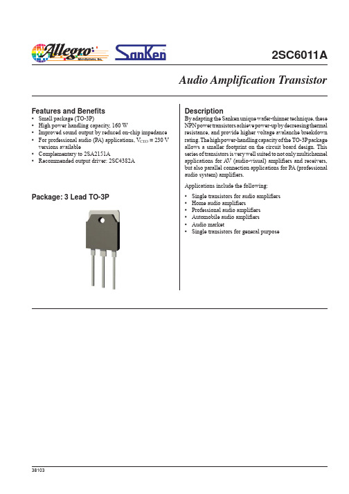
2SC6011ADescriptionBy adapting the Sanken unique wafer-thinner technique, theseNPN power transistors achieve power-up by decreasing thermalresistance, and provide higher voltage avalanche breakdownrating. The high power-handling capacity of the TO-3P packageallows a smaller footprint on the circuit board design. Thisseries of transistors is very well suited to not only multichannelapplications for A V (audio-visual) amplifiers and receivers,but also parallel connection applications for PA (professionalaudio system) amplifiers.Applications include the following:▪Single transistors for audio amplifiers▪Home audio amplifiers▪Professional audio amplifiers▪Automobile audio amplifiers▪ Audio market▪Single transistors for general purposeFeatures and Benefits▪Small package (TO-3P)▪High power handling capacity, 160 W▪Improved sound output by reduced on-chip impedance▪For professional audio (PA) applications, V CEO = 230 Vversions available▪Complementary to 2SA2151A▪Recommended output driver: 2SC4382AAudio Amplification TransistorPackage: 3 Lead TO-3PAudio Amplification Transistor2SC6011A ABSOLUTE MAXIMUM RATINGS at T A = 25°CCharacteristicSymbol Rating Unit Collector-Base Voltage V CBO 230V Collector-Emitter Voltage V CEO 230V Emitter-Base Voltage V EBO 6V Collector Current I C 15A Base CurrentI B 4A Collector Power Dissipation P C 160W Junction Temperature T J 150°C Storage TemperatureT stg–55 to150°CSELECTION GUIDEPart NumberTypeh FE RatingPacking2SC6011A*NPNRange O: 50 to 100Bulk, 100 pieces Range P: 70 tp 140Range Y: 90 to 180*Specify h FE range when ordering. If no h FE range is specified, order will be fulfilled with either or both range O and range Y , depending upon availability.ELECTRICAL CHARACTERISTICS at T A = 25°CCharacteristicSymbol Test ConditionsMin.Typ.Max.Unit Collector-Cutoff Current I CBO V CB = 230 V ––10μA Emitter Cutoff Current I EBO V EB = 6 V ––10μA Collector-Emitter Voltage V (BR)CEOI C = 50 mA 230––V DC Current Transfer Ratio*h FE V CE = 4 V, I C = 3 A 50–180–Collector-Emitter Saturation Voltage V CE(sat)I C = 5 A, I B = 0.5 A ––0.5V Cutoff Frequency f T V CE = 12 V, I E = –0.5 A –20–MHz Output CapacitanceC OBV CB = 10 V, I E = 0 A, f = 1 MHz–270–pF*h FE rating: 50 to 100 (O brand on package), 70 to 140 (P), 90 to 180 (Y).Audio Amplification Transistor2SC6011APerformance CharacteristicsI C (A )I C vs.V CE I C vs.V BEV CE =4V ContinuousI C (A )5h FE vs. I CV CE =4V ContinuousI C (A)h F Et (ms)Audio Amplification Transistor2SC6011AI C (A )V CE (V)Safe Operating AreaT A = 25°C, single pulse, no heatsink, natural cooling 10203040f T vs. I EV CE = 12 V Continuousf T (M H z )I E (A)P C vs. T AT A (°C)P C (W )Performance Characteristics, continuedAudio Amplification Transistor2SC6011ATerminal core material: CuTerminal treatment: Ni plating and solder dip Heat sink core material: Cu Heat sink treatment: Ni plating Leadform number: 100Dimensions in millimetersBranding codes (exact appearance at manufacturer discretion):1st line, type: C6011A2nd line, lot: YM H Where: Y is the last digit of the year of manufacture M is the month (1 to 9, O, N, D )H is the h FE rating (O, P , or Y ; for values see footnote, Electrical Characteristics table)PACKAGE OUTLINE DRAWING, TO-3PLeadframe plating Pb-free. Device composition includes high-temperature solder (Pb >85%), which is exempted from the RoHS directive.Audio Amplification Transistor 2SC6011ABecause reliability can be affected adversely by improper storage environments and handling methods, please observe the following cautions.Cautions for Storage• Ensure that storage conditions comply with the standard temperature (5°C to 35°C) and the standard relative humidity(around 40 to 75%); avoid storage locations that experienceextreme changes in temperature or humidity.• Avoid locations where dust or harmful gases are present and avoid direct sunlight.• Reinspect for rust on leads and solderability of products that have been stored for a long time.Cautions for Testing and HandlingWhen tests are carried out during inspection testing and otherstandard test periods, protect the products from power surgesfrom the testing device, shorts between adjacent products, and shorts to the heatsink.Remarks About Using Silicone Grease with a Heatsink• When silicone grease is used in mounting this product on a heatsink, it shall be applied evenly and thinly. If more siliconegrease than required is applied, it may produce stress.• Coat the back surface of the product and both surfaces of the insulating plate to improve heat transfer between the product and the heatsink.• Volatile-type silicone greases may permeate the product and produce cracks after long periods of time, resulting in reducedheat radiation effect, and possibly shortening the lifetime of theproduct.• Our recommended silicone greases for heat radiation purposes, which will not cause any adverse effect on the product life, areindicated below:Type SuppliersG746Shin-Etsu Chemical Co., Ltd.YG6260GE Toshiba Silicone Co., Ltd.SC102Dow Corning Toray Silicone Co., Ltd.Heatsink Mounting Method• Torque When Tightening Mounting Screws. Thermal resistance increases when tightening torque is low, and radiation effects are decreased. When the torque is too high, the screw can strip, the heatsink can be deformed, and distortion can arise in the product frame.To avoid these problems, observe the recommended tightening torques for this product package type, TO-3P (MT-100): 0.686 to 0.882 N•m (7 to 9 kgf•cm).• Diameter of Heatsink Hole: < 4 mm. The defl ection of the press mold when making the hole may cause the case material to crack at the joint with the heatsink. Please pay special attention for this effect.Soldering• When soldering the products, please be sure to minimize the working time, within the following limits:260±5°C 10 s350±5°C 3 s• Soldering iron should be at a distance of at least 1.5 mm from the body of the productsElectrostatic Discharge• When handling the products, operator must be grounded.Grounded wrist straps worn should have at least 1 MΩ ofresistance to ground to prevent shock hazard.• Workbenches where the products are handled should begrounded and be provided with conductive table and floor mats.• When using measuring equipment such as a curve tracer, the equipment should be grounded.• When soldering the products, the head of soldering irons or the solder bath must be grounded in other to prevent leak voltagesgenerated by them from being applied to the products.• The products should always be stored and transported in our shipping containers or conductive containers, or be wrapped inaluminum foil.Audio Amplification Transistor 2SC6011AThe products described herein are manufactured in Ja p an by Sanken Electric Co., Ltd. for sale by Allegro MicroSystems, Inc.Sanken and Allegro reserve the right to make, from time to time, such de p ar t ures from the detail spec i f i c a t ions as may be re q uired to per m it im-p rove m ents in the per f or m ance, reliability, or manufacturability of its prod u cts. Therefore, the user is cau t ioned to verify that the in f or m a t ion in this publication is current before placing any order.When using the products described herein, the ap p li c a b il i t y and suit a bil i t y of such products for the intended purpose shall be reviewed at the users responsibility.Although Sanken undertakes to enhance the quality and reliability of its prod u cts, the occurrence of failure and defect of semi c on d uc t or products at a certain rate is in e v i t a b le.Users of Sanken products are requested to take, at their own risk, preventative measures including safety design of the equipment or systems against any possible injury, death, fires or damages to society due to device failure or malfunction.Sanken products listed in this publication are designed and intended for use as components in general-purpose electronic equip m ent or apparatus (home ap p li a nc e s, office equipment, tele c om m u n i c a t ion equipment, measuring equipment, etc.). Their use in any application requiring radiation hardness assurance (e.g., aero s pace equipment) is not supported.When considering the use of Sanken products in ap p li c a t ions where higher reliability is re q uired (transportation equipment and its control systems or equip m ent, fire- or burglar-alarm systems, various safety devices, etc.), contact a company sales representative to discuss and obtain written confirmation of your spec i f i c a t ions.The use of Sanken products without the written consent of Sanken in applications where ex t reme l y high reliability is required (aerospace equip-ment, nuclear power-control stations, life-support systems, etc.) is strictly prohibited.The information in c lud e d herein is believed to be accurate and reliable. Ap p li c a t ion and operation examples described in this pub l i c a t ion are given for reference only and Sanken and Allegro assume no re s pon s i b il i t y for any in f ringe m ent of in d us t ri a l property rights, intellectual property rights, or any other rights of Sanken or Allegro or any third party that may result from its use.Anti radioactive ray design is not considered for the products listed herein.Copyright © 2006 Allegro MicroSystems, Inc.This datasheet is based on Sanken datasheet SSE-23015。
BP1808系统应用指南
30.6 37.5 42.3 46.7 51.6 56.9
应用实例
BUCK Dim PWM调光
Dim frequent=200Hz
Dim Duty(%)
1
2
3
Io(mA) 1(不闪) 11
19
Dim Duty(%)
10
20
30Leabharlann Io(mA)71143
216
4
5
6
27
34
41
等等。。。
典型应用 BP1808基本原理
CS A
VOUT
LDO
VDD
1.2V
OVP
PWM Logic OSC
COMP SW GND
DIM
EN/ Dimm in g
BP1808以固定频率400KHz模式工作。通过采集接在CS引脚和VOUT引脚 之间采样电阻上的电压(V-),与内部基准0.2V(V+)比较,通过误差放 大器(EA),控制Comp的电压( V+ ),Comp电压与内部振荡产生的固定 锯齿波(V-)比较,来决定导通时间。当输出电流减小时,采样电阻上的 电压小于0.2V,通过EA把Comp电压拉高,导通时间增大,从而使采样电阻 上的电压维持在0.2V,输出电流维持设定值,反之亦然。
18
设计注意事项 BOOST应用电感选取计算方法
先计算系统工作在零界模式下的电感量:
L
(Vo-Vin) *Vin2 2*Vo2 * Io*f
一般选取以上计算得到的感量的2~4倍。电感选的太小,会使峰值 电流变大,流过MOS和二极管的有效值变大,加大了导通损耗。但是 电感太大,首先,在相同尺寸下感量越大,饱和电流会越小;其次, 感量越大所需的铜线匝数增加,阻抗增加,损耗也增加;最后,加大 电感量会使环路的响应时间变慢。
夏普打印机使用说明书18085

夏普打印机使用说明书000-Cover2.fm Page 0 Wednesday, March 10, 2004 2:26 PM法律禁止复制的物品请不要进行复印或打印。
通常以下项目是各国都禁止复制的,其它未列入项目也可能被法律所禁止。
货币邮票债券股票银行汇票支票护照驾驶证000-Cover3.fm Page 63 Wednesday, March 10, 2004 10:42 AM!001-Contents-dtp.fm Page 1 Wednesday, March 10, 2004 10:54 AM目录小心.............................................................................. (3)环境信息.............................................................................. .. (5)绪论.............................................................................. (6)主要功能....................................................................................................................7组件名称.............................................................................. (9)打开和关闭电源.........................../doc/662930fb910ef12d2af9 e7b4.html.. (12)纸张.............................................................................. .. (14)加载纸盒.............................................................................. . (15)手送(包括特殊纸张)............................................................................ (17)更改纸盒的纸张尺寸设置.............................................................................. ...19普通复印.............................................................................. . (20)选择纸盒.............................................................................. . (23)使复印件加深或变 (24)缩小/放大/变焦...........................................................http://www.wenkuxia /doc/662930fb910ef12d2af9e7b4.html.................................25自动双面复印.............................................................................. (26)整理复印.............................................................................. . (29)在一页纸上复印几页原稿(二合一复印) (31)复印时建立边位(边位移动) (34)AR-158F的软件.............................................................................. . (36)安装之前.............................................................................. . (37)软件安装.............................................................................. . (38)Manager......................................................................... .. (51)将机器连接到您的计算机..../doc/662930fb910ef12d2af9e7b4.html.............. (551)!001-Contents-dtp.fm Page 2 Wednesday, March 10, 2004 10:54 AM使用打印机模式.............................................................................. .. (58)打印的基本步骤.............................................................................. .. (58)使用扫描仪模式.............................................................................. .. (59)使用机器上的按键扫描.............................................................................. . (59)从您的计算机进行扫描.............................................................................. . (60)在复印、打印和扫描模式下的操如何使用联机手册.............................................................................. ..............61用户程序.................../doc/662930fb910ef12d2af9e7b4.htm l............................................................................... .. (62)在用户程序中选择一个设置 (6)7显示信息.............................................................................. . (69)机器的故障检修.............................................................................. .. (71)安装软件过程中出现的问题 (7)5清除卡纸.............................................................................. . (79)更换墨粉盒.............................................................................. . (83)关.............................................................................. .. (86)检查总计数.................................................... /doc/662930fb910ef12d2af9e7b4.html.............................................. .. (87)常规维护.............................................................................. . (87)清洁机器.............................................................................. ............................88系统配置.............................................................................. . (90)网络扫描扩展组件(AR-NB2 N)........................................................................90规格.............................................................................. .. (91)索引.............................................................................. .. (962)!002-Cautions.fm Page 3 Wednesday, March 10, 2004 1:29 PM小心机器上的小心标签机器定影区上的小心标记(如下表示:小心,危险小心,表面烫使用机器时/doc/662930fb910ef12d2af9e7b4.html要小心的事项使用机器时要小心下面的事项。
517操作说明书
05pmii选择复印纸23预设缩小放大24缩放24分页25更改份数26用单面纸复印身份证两面用户工具用户工具菜单系统设置29用户工具菜单复印机设置31访问用户工具32更改默认设置32退出用户工具33可以通过用户工具更改的设置34系统设置34复印机功能37用户代码39注册新的用户代码39更改用户代码40删除用户代码40显示每个用户代码的计数器41打印每个用户代码的计数器41清除计数器故障排除如果本机不能正常工作43复印件不清晰44无法正常复印45内存空间用尽时45b装入纸张46装入纸张46方向固定的纸张或双面纸张47d添加碳粉48处理碳粉48碳粉存放48用过的碳粉48取出碳粉49加碳粉50kirc3azhopebookpageiiwednesdaymarch20103
PandaC4cpyZH_Cover1.fm Page 1 Sunday, April 25, 2010 8:43 AM
AM1808核心板规格书
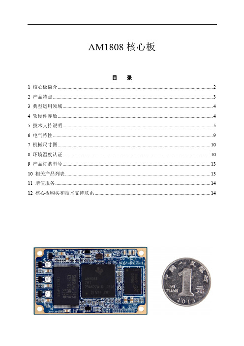
AM1808核心板目录1 核心板简介 (2)2 产品特点 (3)3 典型运用领域 (4)4 软硬件参数 (4)5 技术支持说明 (5)6 电气特性 (9)7 机械尺寸图 (10)8 环境温度认证 (10)9 产品订购型号 (13)10 相关产品列表 (13)11 增值服务 (14)12 核心板购买和技术支持联系 (14)1核心板简介基于TI AM1808 ARM9 CPU,标配工业级,主频456MHz;55mm*33mm,全国最小AM1808 ARM9核心板,采用精密工业级B2B连接器; TI推荐的超低功耗ARM处理器,适用于便携式设备;标配512MByte工业级NAND FLASH;标配128MByte工业级DDR2,可升级到256MByte;标配Linux操作系统、支持WinCE操作系统;通过环境测试认证,满足工业环境应用;图1 SOM-TL1808正面图2 SOM-TL1808背面由广州创龙自主研发的SOM-TL1808是全国最小的ARM1808 ARM9工业级核心板,55mm*33mm,仅硬币大小,功耗小、成本低、性价比高。
采用沉金无铅工艺的六层板设计,专业的PCB Layout保证信号完整性的同时,还经过严格的质量控制,通过环境测试认证,满足工业环境应用。
SOM-TL1808引出CPU全部资源信号引脚,二次开发极其容易,客户只需要专注上层运用,降低了开发难度和时间成本,让产品快速上市,及时抢占市场先机。
不仅提供丰富的Demo程序,还提供详细的开发教程,全面的技术支持,协助客户进行底板设计和调试以及软件开发。
2产品特点基于TI AM1808 ARM9工业级处理器,性价比极高,面向低成本工业系统;全国最小AM1808 ARM9核心板,55mm*33mm,仅硬币大小,减少占用空间;集成uPP、EMIF、SATA、USB 2.0等大数据传输接口,可与FPGA/CPLD配套使用;电源经过精心设计,功耗极低,发热量极小,手持设备首选;工业级核心板,遵循工业级设计,适合各种恶劣的工作环境;工业级精密B2B连接器,0.5mm间距,比排针和金手指更稳定,易插拔,防反插;3典型运用领域✓低成本数控系统✓海量数据存储设备✓智能家居✓智能网关✓智能电力系统✓便携式设备✓数据采集处理设备4软硬件参数硬件参数表1 硬件参数备注:广州创龙的OMAPL138、TMS320C6748、AM1808核心板在硬件上Pin to Pin兼容。
多功能教室设备值
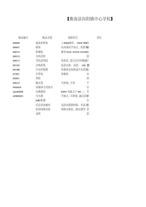
【衡南县向阳镇中心学校】
物品编号物品名称规格型号单位
00006液晶投影机≥3000流明、1024*768台
00007银幕电动幕或手动式,投影机幅
00010影碟机兼容VCD、SVCD、DVCD、台
00013无线话筒套
00017耳机话筒组高保真,适合长时间佩戴个
套
00122音响系统成套设备:包括:CD、功
00188中央控制器多媒体设备集成中央系统台
01001计算机多媒体台
02001黑板块
25012激光笔可伸缩,专用个
F00029多媒体专用讲台台
syssb006电源插座220V,电流大于6A,二、三个
x0900001灭火器手提式,不锈钢,通过国家个
GA分配器台
信息设备辅材包括电源插线板、水晶头批
校园网络设备网络交换机、路由器等套
桌椅套。
cc1150中文
第 - 2 - 页 共 46 页
目录 1 缩写词 ......................................................................................................................................... 2 2 绝对最大等级 ............................................................................................................................. 5 3 工作条件 ..................................................................................................................................... 5 4 电气规范 ..................................................................................................................................... 5 5 常规特性 ..................................................................................................................................... 6 6 RF 传输环节 .............................................................
pcm1808

BurrĆBrown Productsfrom TexasInstrumentsFEATURES APPLICATIONSDESCRIPTIONPCM1808SLES177A–APRIL2006–REVISED AUGUST2006 SINGLE-ENDED,ANALOG-INPUT24-BIT,96-kHz STEREO A/D CONVERTER•DVD Recorder•24-Bit Delta-Sigma Stereo A/D Converter•Digital TV•Single-Ended Voltage Input:3Vp-p•AV Amplifier/Receiver•High Performance:•MD Player–THD+N:–93dB(Typical)•CD Recorder–SNR:99dB(Typical)•Multitrack Receiver–Dynamic Range:99dB(Typical)•Electric Musical Instrument •Oversampling Decimation Filter:–Oversampling Frequency:×64–Pass-Band Ripple:±0.05dB The PCM1808is high-performance,low-cost,–Stop-Band Attenuation:–65dB single-chip,stereo analog-to-digital converter withsingle-ended analog voltage input.The PCM1808–On-Chip High-Pass Filter:0.91Hz(48kHz)uses a delta-sigma modulator with64-times •Flexible PCM Audio Interfaceoversampling and includes a digital decimation filter –Master/Slave Mode Selectable and high-pass filter that removes the dc componentof the input signal.For various applications,the –Data Formats:24-Bit I2S,24-BitPCM1808supports master and slave mode and two Left-Justifieddata formats in serial audio interface.•Power Down and Reset by Halting SystemThe PCM1808supports the power-down and reset Clockfunction by means of halting the system clock.•Analog Antialias LPF IncludedThe PCM1808is suitable for wide variety of •Sampling Rate:8kHz–96kHzcost-sensitive consumer applications where good •System Clock:256f S,384f S,512f Sperformance and operation with a5-V analog supply •Dual Power Supplies:and3.3-V digital supply is required.The PCM1808isfabricated using a highly advanced CMOS process –5-V for Analogand is available in a small,14-pin TSSOP package.–3.3-V for Digital•Package:14-Pin TSSOPPlease be aware that an important notice concerning availability,standard warranty,and use in critical applications of TexasInstruments semiconductor products and disclaimers thereto appears at the end of this data sheet.System Two,Audio Precision are trademarks of Audio Precision,Inc.All other trademarks are the property of their respective owners.PRODUCTION DATA information is current as of publication date.Copyright©2006,Texas Instruments Incorporated Products conform to specifications per the terms of the TexasInstruments standard warranty.Production processing does notnecessarily include testing of all parameters.RECOMMENDED OPERATING CONDITIONSPCM1808SLES177A–APRIL 2006–REVISED AUGUST 2006This integrated circuit can be damaged by ESD.Texas Instruments recommends that all integrated circuits be handled with appropriate precautions.Failure to observe proper handling and installation procedures can cause damage.ESD damage can range from subtle performance degradation to complete device failure.Precision integrated circuits may be more susceptible to damage because very small parametric changes could cause the device not to meet its published specifications.over operating free-air temperature range (unless otherwise noted)(1)PCM1808Analog supply voltage,V CC –0.3V to 6.5V Digital supply voltage,V DD–0.3V to 4V Ground voltage differences,AGND,DGND ±0.1VDigital input voltage,LRCK,BCK,DOUT –0.3V to (V DD +0.3V)<4VDigital input voltage,SCKI,MD0,MD1,FMT –0.3V to 6.5VAnalog input voltage,V IN L,V IN R,V REF –0.3V to (V CC +0.3V)<6.5VInput current (any pins except supplies)±10mA Ambient temperature under bias,T A –40°C to 125°C Storage temperature,T stg –55°C to 150°CJunction temperature,T J 150°C Lead temperature (soldering)260°C,5s Package temperature (reflow,peak)260°C(1)Stresses beyond those listed under "absolute maximum ratings"may cause permanent damage to the device.These are stress ratings only,and functional operation of the device at these or any other conditions beyond those indicated under "recommended operating conditions"is not implied.Exposure to absolute-maximum-rated conditions for extended periods may affect device reliability.over operating free-air temperature range (unless otherwise noted)MINNOMMAX UNIT Analog supply voltage,V CC 4.55 5.5V Digital supply voltage,V DD2.73.3 3.6V Analog input voltage,full scale (–0dB)V CC =5V3Vp-pDigital input logic familyTTL compatibleDigital input clock frequency,system clock 2.04849.152MHz Digital input clock frequency,sampling clock 896kHz Digital output load capacitance 20pF Operating free-air temperature,T A–4085°C2Submit Documentation FeedbackELECTRICAL CHARACTERISTICSPCM1808 SLES177A–APRIL2006–REVISED AUGUST2006All specifications at TA =25°C,VCC=5V,VDD=3.3V,master mode,fS=48kHz,system clock=512fS,24-bit data,unlessotherwise notedPARAMETER TEST CONDITIONS MIN TYP MAX UNIT Resolution24Bits DATA FORMATAudio data interface format I2S,left-justifiedAudio data bit length24BitsAudio data format MSB-first,2s complementf S Sampling frequency84896kHz256f S 2.04812.28824.576 System clock frequency384f S 3.07218.43236.864MHz512f S 4.09624.57649.152INPUT LOGICV IH(1)2V DDV IL(1)00.8 Input logic level VDCV IH(2)(3)2 5.5V IL(2)(3)00.8I IH(2)V IN=V DD±10I IL(2)V IN=0V±10Input logic currentµAI IH(1)(3)V IN=V DD65100I IL(1)(3)V IN=0V±10OUTPUT LOGICV OH(4)I OUT=–4mA 2.8Output logic level VDCV OL(4)I OUT=4mA0.5DC ACCURACYGain mismatch,channel-to-channel±1±3%of FSRGain error±3±6%of FSR DYNAMIC PERFORMANCE(5)V IN=–0.5dB,f S=48kHz–93–87V IN=–0.5dB,f S=96kHz(6)–87THD+N Total harmonic distortion+noise dBV IN=–60dB,f S=48kHz–37V IN=–60dB,f S=96kHz(6)–39f S=48kHz,A-weighted9599Dynamic range dBf S=96kHz,A-weighted(6)101f S=48kHz,A-weighted9599S/N Signal-to-noise ratio dBf S=96kHz,A-weighted(6)101f S=48kHz9397Channel separation dBf S=96kHz(6)91(1)Pins7,8:LRCK,BCK(Schmitt-trigger input,with50-kΩtypical pulldown resistor,in slave mode)(2)Pin6:SCKI(Schmitt-trigger input,5-V tolerant)(3)Pins10–12:MD0,MD1,FMT(Schmitt-trigger input,with50-kΩtypical pulldown resistor,5-V tolerant)(4)Pins7–9:LRCK,BCK(in master mode),DOUT(5)Analog performance specifications are tested using a System Two™audio measurement system by Audio Precision™with400-Hz HPFand20-kHz LPF in RMS mode.(6)f S=96kHz,system clock=256f S.3Submit Documentation FeedbackPCM1808SLES177A–APRIL 2006–REVISED AUGUST 2006ELECTRICAL CHARACTERISTICS (continued)All specifications at T A =25°C,V CC =5V,V DD =3.3V,master mode,f S =48kHz,system clock =512f S ,24-bit data,unless otherwise notedPARAMETERTEST CONDITIONS MIN TYP MAX UNIT ANALOG INPUTInput voltage 0.6V CC Vp-p Center voltage (V REF )0.5V CCV Input impedance60k ΩAntialiasing filter frequency –3dB 1.3MHzresponseDIGITAL FILTER PERFORMANCEPass band 0.454f SHz Stop band 0.583f SHz Pass-band ripple ±0.05dB Stop-band attenuation –65dBDelay time17.4/f SHPF frequency response–3dB0.019f S /1000POWER SUPPLY REQUIREMENTS V CC 4.55 5.5Voltage rangeVDC V DD 2.73.3 3.6f S =48kHz,96kHz (8)8.611mA I CCPowered down (9)1µA Supply current(7)f S =48kHz 5.98mA I DDf S =96kHz (8)10.2mA Powered down(9)150µAf S =48kHz6281mW Power dissipation(7)f S =96kHz(8)77Powered down(9)500µW TEMPERATURE RANGE T A Operation temperature –4085°C θJA Thermal resistance170°C/W(7)Minimum load on LRCK (pin 7),BCK (pin 8),DOUT (pin 9)(8)f S =96kHz,system clock =256f S .(9)Power-down and reset functions enabled by halting SCKI,BCK,LRCK.4Submit Documentation FeedbackPIN ASSIGNMENTSV REF AGNDV CCV DD DGND SCKI LRCKV IN RV IN LFMTMD1MD0DOUTBCKPW PACKAGE(TOP VIEW)P0032-02PCM1808SLES177A–APRIL2006–REVISED AUGUST2006 TERMINAL FUNCTIONSTERMINAL I/O DESCRIPTIONNAME PINAGND2–Analog GNDBCK8I/O Audio data bit clock input/output(1)DGND5–Digital GNDDOUT9O Audio data digital outputFMT12I Audio interface format select(2)LRCK7I/O Audio data latch enable input/output(1)MD010I Audio interface mode select0(2)MD111I Audio interface mode select1(2)SCKI6I System clock input;256f S,384f S or512f S(3)V CC3–Analog power supply,5-VV DD4–Digital power supply,3.3-VV IN L13I Analog input,L-channelV IN R14I Analog input,R-channelV REF1–Reference voltage decoupling(=0.5V CC)(1)Schmitt-trigger input with internal pulldown(50-kΩ,typical)(2)Schmitt-trigger input with internal pulldown(50-kΩ,typical),5-V tolerant(3)Schmitt-trigger input,5-V tolerant5Submit Documentation FeedbackBCK V IN LV REFV IN RAGND V CCV DDDGNDLRCK DOUT SCKIB0004-10FMT MD1MD0TYPICAL PERFORMANCE CURVES OF INTERNAL FILTERSDECIMATION FILTER FREQUENCY RESPONSE−200−150−100−5050A m p l i t u d e − d BG001−100−90−80−70−60−50−40−30−20−100A m p l i t u d e − d BG002PCM1808SLES177A–APRIL 2006–REVISED AUGUST 2006Functional Block DiagramAll specifications at T A =25°C,V CC =5V,V DD =3.3V,master mode,f S =48kHz,system clock =512f S ,24-bit data,unless otherwise noted.OVERALL CHARACTERISTICSSTOP-BAND ATTENUATION CHARACTERISTICS6Submit Documentation FeedbackTYPICAL PERFORMANCE CURVES OF INTERNAL FILTERS (Continued)DECIMATION FILTER FREQUENCY RESPONSE (Continued)G003Normalized Frequency [× f S ]−1.0−0.8−0.6−0.4−0.20.00.2A m p l i t u d e − d BG004Normalized Frequency [× f S ]−10−9−8−7−6−5−4−3−2−100.450.460.470.480.490.500.510.520.530.540.55A m p l i t u d e − d BHIGH-PASS FILTER FREQUENCY RESPONSEG005−100−90−80−70−60−50−40−30−20−100A m p l i t u d e − d BG006−1.0−0.8−0.6−0.4−0.20.00.2A m p l i t u d e − d BPCM1808SLES177A–APRIL 2006–REVISED AUGUST 2006All specifications at T A =25°C,V CC =5V,V DD =3.3V,master mode,f S =48kHz,system clock =512f S ,24-bit data,unless otherwise noted.PASS-BAND RIPPLE CHARACTERISTICSTRANSITION BAND CHARACTERISTICSFigure 3.Figure 4.HPF STOP-BAND CHARACTERISTICSHPF PASS-BAND CHARACTERISTICSFigure 6.7Submit Documentation FeedbackTYPICAL PERFORMANCE CURVESG007−97−96−95−94−93−92−91−90−89−88−87−50−25255075100T A − Free-Air Temperature − °C T H D + N − T o t a l H a r m o n i c D i s t o r t i o n + N o i s e − dB9596979899100101102103104105−50−25255075100G008T A − Free-Air Temperature − °CD y n a m i c R a n g e a n d S N R − d B−97−96−95−94−93−92−91−90−89−88−874.254.504.755.005.255.505.75V CC − Supply Voltage − V T H D + N − T o t a l H a r m o n i c D i s t o r t i o n + N o i s e − d BG009G01095969798991001011021031041054.254.504.755.005.255.505.75V CC − Supply Voltage − VD y n a m i c R a n g e a n d S N R − d BPCM1808SLES177A–APRIL 2006–REVISED AUGUST 2006All specifications at T A =25°C,V CC =5V,V DD =3.3V,master mode,f S =48kHz,system clock =512f S ,24-bit data,unless otherwise noted.THD +N DYNAMIC RANGE AND SNRvsvsTEMPERATURETEMPERATUREFigure 7.Figure 8.THD +N DYNAMIC RANGE AND SNRvsvsSUPPLY VOLTAGESUPPLY VOLTAGEFigure 9.Figure 10.8Submit Documentation FeedbackTYPICAL PERFORMANCE CURVES (Continued)−97−96−95−94−93−92−91−90−89−88−87T H D + N − T o t a l H a r m o n i c D i s t o r t i o n + N o i s e − d B44.1(1)96(3)48(2)G011f SAMPLE Condition − kHz9596979899100101102103104105D y n a m i c R a n g e a n d S N R − d BG01244.1(1)96(3)48(2)f SAMPLE Condition − kHzOUTPUT SPECTRUMG013f − Frequency − kHz−140−120−100−80−60−40−20005101520A m p l i t u d e − d BG014f − Frequency − kHz−140−120−100−80−60−40−2005101520A m p l i t u d e − d BPCM1808SLES177A–APRIL 2006–REVISED AUGUST 2006All specifications at T A =25°C,V CC =5V,V DD =3.3V,master mode,f S =48kHz,system clock =512f S ,24-bit data,unless otherwise noted.THD +N DYNAMIC RANGE AND SNRvsvsf SAMPLE CONDITIONf SAMPLE CONDITIONFigure 11.Figure 12.OUTPUT SPECTRUM (–0.5dB,N =8192)OUTPUT SPECTRUM (–60dB,N =8192)Figure 13.Figure 14.9Submit Documentation FeedbackTYPICAL PERFORMANCE CURVES (Continued)OUTPUT SPECTRUM (Continued)−100−90−80−70−60−50−40−30−20−100−100−90−80−70−60−50−40−30−20−10Signal Level − dBT H D + N − T o t a l H a r m o n i c D i s t o r t i o n + N o i s e − d BG015SUPPLY CURRENT51015I C C a n d I D D − S u p p l y C u r r e n t − m AG01644.1(1)96(3)48(2)f SAMPLE Condition − kHzPCM1808SLES177A–APRIL 2006–REVISED AUGUST 2006All specifications at T A =25°C,V CC =5V,V DD =3.3V,master mode,f S =48kHz,system clock =512f S ,24-bit data,unless otherwise noted.THD +N vsSIGNAL LEVELFigure 15.SUPPLY CURRENTvsf SAMPLE CONDITIONFigure 16.10Submit Documentation FeedbackSYSTEM CLOCKSCKI0.8 VSCKI 2 VT0005B07FADE-IN AND FADE-OUT FUNCTIONSPCM1808SLES177A–APRIL 2006–REVISED AUGUST 2006The PCM1808supports 256f S ,384f S and 512f S as system clock,where f S is the audio sampling frequency.The system clock must be supplied on SCKI (pin 6).The PCM1808has a system clock detection circuit which automatically senses if the system clock is operating at 256f S ,384f S ,or 512f S in slave mode.In master mode,the system clock frequency must be controlled through the serial control port,which uses MD1(pin 111)and MD0(pin 10).The system clock is divided down automatically to generate frequencies of 128f S and 64f S ,which are used to operate the digital filter and the delta-sigma modulator,respectively.Table 1shows some typical relationships between sampling frequency and system clock frequency,and Figure 17shows system clock timing.Table 1.Sampling Frequency and System Clock FrequencySAMPLING FREQUENCY (kHz)SYSTEM CLOCK FREQUENCY (f SCLK )(MHz)256f S384f S 512f S 8 2.048 3.072 4.09616 4.096 6.1448.192328.19212.28816.38444.111.289616.934422.57924812.28818.43224.5766416.38424.57632.76888.222.579233.868845.15849624.57636.86449.152SYMBOL PARAMETERMIN MAX UNIT t w(SCKH)System clock pulse duration,HIGH 8ns t w(SCKL)System clock pulse duration,LOW 8nsSystem clock duty cycle40%60%Figure 17.System Clock TimingThe PCM1808has fade-in and fade-out functions on DOUT (pin 9)to avoid pop noise,and the functions come into operation in some cases as described in several following sections.The level changes from 0dB to mute or mute to 0dB are performed using calculated pseudo S-shaped characteristics with zero-cross detection.Because of the zero-cross detection,the time needed for the fade in and fade out depends on the analog input frequency (f in ).It takes 48/f in until processing is completed.If there is no zero cross during 8192/f S ,DOUT is faded in or out by force during 48/f S (TIME OUT).Figure 18illustrates the fade-in and fade-out operation processing.11Submit Documentation FeedbackBPZDOUT (Contents)T0080-01POWER ONV DDInternal ResetSystem ClockDOUT T0014-09DOUT(Contents)PCM1808SLES177A–APRIL 2006–REVISED AUGUST 2006Figure 18.Fade-In and Fade-Out OperationsThe PCM1808has an internal power-on-reset circuit,and initialization (reset)is performed automatically when the power supply (V DD )exceeds 2.2V (typical).While V DD <2.2V (typical),and for 1024system-clock counts after V DD >2.2V (typical),the PCM1808stays in the reset state and the digital output is forced to zero.The digital output is valid after the reset state is released and the time of 8960/f S has elapsed.Because the fade-in operation is performed,it takes additional time of 48/f in or 48/f S until the data corresponding to the analog input signal is obtained.Figure 19illustrates the power-on timing and the digital output.Figure 19.Power-On Timing12Submit Documentation FeedbackCLOCK-HALT POWER-DOWN AND RESET FUNCTIONSCKI T0081-01Internal ResetDOUT DOUT(Contents)SCKI HaltSCKI ResumePCM1808SLES177A–APRIL 2006–REVISED AUGUST 2006The PCM1808has a power-down and reset function,which is triggered by halting SCKI (pin 6)in both master and slave modes.The function is available anytime after power on.Reset and power down are performed automatically 4µs (minimum)after SCKI is halted.While the clock-halt reset is asserted,the PCM1808stays in the reset and power-down mode,and DOUT (pin 9)is forced to zero.SCKI must be supplied to release the reset and power-down mode.The digital output is valid after the reset state is released and the time of 1024SCKI +8960/f S has elapsed.Because the fade-in operation is performed,it takes additional time of 48/f in or 48/f S until the level corresponding to the analog input signal is obtained.Figure 20illustrates the clock-halt reset timing.To avoid ADC performance degradation,BCK (pin 8)and LRCK (pin 7)are required to synchronize with SCKI within 4480/f S after SCKI is resumed.If it takes more than 4480/f S for BCK and LRCK to synchronize with SCKI,SCKI should be masked until the synchronization is achieved again,taking care of glitch and jitter.See the typical circuit connection diagram,Figure 26.To avoid ADC performance degradation,the clock-halt reset also should be asserted when system clock SCKIor the audio interface clocks BCK and LRCK (sampling rate f S )are changed on the fly.SYMBOL PARAMETERMIN MAX UNIT t (CKR)Delay time from SCKI halt to internal reset 4µs t (RST)Delay time from SCKI resume to reset release 1024SCKI µs t (REL)Delay time from reset release to DOUT output8960/f SµsFigure 20.Clock-Halt Power-Down and Reset Timing13Submit Documentation FeedbackSERIAL AUDIO DATA INTERFACEINTERFACE MODEDATA FORMATPCM1808SLES177A–APRIL 2006–REVISED AUGUST 2006The PCM1808interfaces the audio system through LRCK (pin 7),BCK (pin 8),and DOUT (pin 9).The PCM1808supports master mode and slave mode as interface modes,which are selected by MD1(pin 11)and MD0(pin 10),as shown in Table 2.MD1and MD0must be set prior to power on.In master mode,the PCM1808provides the timing of serial audio data communications between the PCM1808and the digital audio processor or external circuit.While in slave mode,the PCM1808receives the timing for data transfer from an external controller.Table 2.Interface ModesMD1(Pin 11)MD0(Pin 10)INTERFACE MODELow Low Slave mode (256f S ,384f S ,512f S autodetection)Low High Master mode (512f S )High Low Master mode (384f S )HighHighMaster mode (256f S )Master modeIn master mode,BCK and LRCK work as output pins,and these pins are controlled by timing which is generated in the clock circuit of the PCM1808.The frequency of BCK is fixed at 64BCK/frame.Slave modeIn slave mode,BCK and LRCK work as input pins.The PCM1808accepts 64-BCK/frame or 48-BCK/frame format (only for a 384-f S system clock),not 32-BCK/frame format.The PCM1808supports two audio data formats in both master and slave modes.The data formats are selected by FMT (pin 12),as shown in Table 3.Figure 21illustrates the data formats in slave mode and master mode.Table 3.Data FormatFORMAT NO.FMT (Pin 12)FORMAT0Low I 2S,24-bit1HighLeft-justified,24-bit14Submit Documentation FeedbackLRCK Right-ChannelLeft-ChannelBCK DOUTMSB LSBMSBLSB24-Bit, MSB-First, I 2SFORMAT 0: FMT = LOW22232432122232432124-Bit, MSB-First, Left-JustifiedBCK LRCK Right-ChannelLeft-Channel DOUT1222324321MSB LSBMSBLSB222324321FORMAT 1: FMT = HIGHT0016-17PCM1808SLES177A–APRIL 2006–REVISED AUGUST 2006Figure 21.Audio Data Format (LRCK and BCK Work as Inputs in Slave Modeand as Outputs in Master Mode)15Submit Documentation FeedbackINTERFACE TIMINGBCKLRCKDOUTT0017-02PCM1808SLES177A–APRIL 2006–REVISED AUGUST 2006Figure 22and Figure 23illustrate the interface timing in slave mode and master mode,respectively.SYMBOL PARAMETERMIN TYP MAX UNIT t (BCKP)BCK period1/(64f S )ns t (BCKH)BCK pulse duration,HIGH 1.5×t (SCKI)ns t (BCKL)BCK pulse duration,LOW1.5×t (SCKI)ns t (LRSU)LRCK setup time to BCK rising edge 50ns t (LRHD)LRCK hold time to BCK rising edge 10ns t (LRCP)LRCK period10µst (CKDO)Delay time,BCK falling edge to DOUT valid –1040ns t (LRDO)Delay time,LRCK edge to DOUT valid –1040ns t r Rise time of all signals 20ns t fFall time of all signals20nsNOTE:Timing measurement reference level is 1.4V for input and 0.5V DD for output.Rise and fall times are from 10%to90%of the input/output signal swing.Load capacitance of DOUT is 20pF.t (SCKI)is the SCKI period.Figure 22.Audio Data Interface Timing (Slave Mode:LRCK and BCK Work as Inputs)16Submit Documentation FeedbackBCKLRCKDOUTT0018-02BCKSCKIT0074-01PCM1808SLES177A–APRIL 2006–REVISED AUGUST 2006SYMBOL PARAMETERMIN TYP MAX UNIT t (BCKP)BCK period1501/(64f S )2000ns t (BCKH)BCK pulse duration,HIGH 651200ns t (BCKL)BCK pulse duration,LOW651200ns t (CKLR)Delay time,BCK falling edge to LRCK valid –1020ns t (LRCP)LRCK period101/f S125µs t (CKDO)Delay time,BCK falling edge to DOUT valid –1020ns t (LRDO)Delay time,LRCK edge to DOUT valid –1020ns t r Rise time of all signals 20ns t fFall time of all signals20nsNOTE:Timing measurement reference level is 0.5V DD .Rise and fall times are from 10%to 90%of the input/output signalswing.Load capacitance of all signals is 20pF.Figure 23.Audio Data Interface Timing (Master Mode:LRCK and BCK Work as Outputs)SYMBOL PARAMETERMIN TYP MAX UNIT t (SCKBCK)Delay time,SCKI rising edge to BCK edge530nsNOTE:Timing measurement reference level is 1.4V for input and 0.5V DD for output.Load capacitance of BCK is 20pF.This timing is applied when SCKI frequency is less than 25MHz.Figure 24.Audio Clock Interface Timing (Master Mode:BCK Works as Output)17Submit Documentation FeedbackSYNCHRONIZATION WITH DIGITAL AUDIO SYSTEMT0082-01DOUT DOUT(Contents)BPZState ofSynchronizationResynchronizationResynchronizationPCM1808SLES177A–APRIL 2006–REVISED AUGUST 2006In slave mode,the PCM1808operates under LRCK (pin 7),synchronized with system clock SCKI (pin 6).The PCM1808does not require a specific phase relationship between LRCK and SCKI,but does require the synchronization of LRCK and SCKI.If the relationship between LRCK and SCKI changes more than ±6BCKs for 64BCK/frame (±5BCKs for 48BCK/frame)during one sample period due to LRCK or SCKI jitter,internal operation of the ADC halts within 1/f S and digital output is forced to zero data (BPZ code)until resynchronization between LRCK and SCKI is established.In the case of changes less than ±5BCKs for 64BCK/frame (±4BCKs for 48BCK/frame),resynchronization does not occur and the previously described digital output control and discontinuity do not occur.Figure 25illustrates the digital output response for loss of synchronization and resynchronization.During data,the PCM1808can generate some noise in the audio signal.Also,the transition of normal data to undefined data creates a discontinuity in the digital output data,which can generate some noise in the audio signal.The digital output is valid after resynchronization completes and the time of 32/f S has elapsed.Because the fade-in operation is performed,it takes additional time of 48/f in or 48/f S until the level corresponding to the analog input signal is obtained.If synchronization is lost during the fade-in or fade-out operation,the operation stops and DOUT (pin 9)is forced to zero data immediately.The fade-in operation resumes from mute after the time of 32/f S following resynchronization.Figure 25.ADC Digital Output for Loss of Synchronization and Resynchronization18Submit Documentation FeedbackAPPLICATION INFORMATIONTYPICAL CIRCUIT CONNECTION DIAGRAMS0113-02L-ch INR-ch IN BOARD DESIGN AND LAYOUT CONSIDERATIONSV CC ,V DD PINSAGND,DGND PINSV IN L,V IN R PINSPCM1808SLES177A–APRIL 2006–REVISED AUGUST 2006Figure 26is a typical circuit connection diagram.The antialiasing low-pass filters are integrated on the analog IN L and V IN R.If the performance of these filters is not adequate for an application,appropriate external antialiasing filters are needed.A passive RC filter (100Ωand 0.01µF to 1k Ωand 1000pF)generally is used.(1)C1,C2:A 1-µF electrolytic capacitor gives 2.7Hz (τ=1µF ×60k Ω)cutoff frequency for the input HPF in normal operation and requires a power-on settling time with a 60-ms time constant in the power-on initialization period.(2)C3,C4:Bypass capacitors,0.1-µF ceramic and 10-µF electrolytic,depending on layout and power supply (3)C5:0.1-µF ceramic and 10-µF electrolytic capacitors are recommended.(4)X1:X1masks the system clock input when using the clock-halt reset function with external control.(5)Optional external antialiasing filter could be required,depending on the application.Figure 26.Typical Circuit Connection DiagramThe digital and analog power supply lines to the PCM1808should be bypassed to the corresponding ground pins with both 0.1-µF ceramic and 10-µF electrolytic capacitors as close to the pins as possible to maximize the dynamic performance of the ADC.To maximize the dynamic performance of the PCM1808,the analog and digital grounds are not internally connected.These grounds should have low impedance to avoid digital noise feedback into the analog ground.They should be connected directly to each other under the PCM1808package to reduce potential noise problems.V IN L and V IN R are single-ended inputs.The antialias low-pass filters are integrated on these inputs to remove the high-frequency noise outside the audio band.If the performance of these filters is not adequate for an application,appropriate external antialiasing filters are required.A passive RC filter (100Ωand 0.01µF to 1k Ωand 1000pF)is generally used.19Submit Documentation FeedbackV REF PINDOUT PINSYSTEM CLOCKPCM1808SLES177A–APRIL 2006–REVISED AUGUST 2006APPLICATION INFORMATION (continued)To ensure low source impedance of the ADC references,0.1-µF ceramic and 10-µF electrolytic capacitors are recommended between V REF and AGND.These capacitors should be located as close as possible to the V REF pin to reduce dynamic errors on the ADC references.The DOUT pin has a large load-drive capability,but if the DOUT line is long,locating a buffer near the PCM1808and minimizing load capacitance is recommended to minimize the digital-analog crosstalk and maximize the dynamic performance of the ADC.The quality of the system clock can influence dynamic performance,as the PCM1808operates based on a system clock.Therefore,it may be necessary to consider the system clock duty,jitter,and the time difference between system clock transition and BCK or LRCK transition in slave mode.20Submit Documentation Feedback。
Parker Hannifin Corporation PB180828-156 产品说明说明书

PB180828-156© 2018 Parker Hannifin Corporation Parker Hannifin CorporationIndustrial Gas Filtration and Generation Division 11501 Outlook Street, Suite 100 There are typically two basic problems with pulse valves: they won’t open, or they won’t close. The problem may be the valve housing is visibly cracked or broken, but frequently the cause is less obvious, and may not be within the valve itself.It is important to evaluate the entire pulsing system, from the air supply to the solenoid valve, and the timer.Problem:Valve will not openPotential Causes:• No power to timer or solenoids, or faulty steps in the timer • S olenoid coil continuity• B uildup of debris (oil, dirt, etc.) in solenoid plunger sleeve • T ubing between solenoid and pulse valve blocked• T ubing interior diameter less than 0.160 in. (4mm) or tubing length greater than 8 ft. (2.4 m)• Solenoid plunger worn • Holes in diaphragm • Blocked exhaust portsProblem:Valve will not close (leaks air)Potential Causes:• Solenoid leaks air• L eaks in tubing between solenoid and pulse valve • S olenoid continuously energized • Insufficent air supply• B locked bleedports in pulse valve housing • Bad seal at primary diaphragm seat • Broken diaphragm springsRecommendations:When troubleshooting any process equipment, it is important to follow all applicable safety procedures.Air Supply:At startup, and especially when new, quick pressurization is needed to fully seal and equalize pres s ure in the valve for proper operation. This type of valve uses equalized air pressures on un e qual surface areas to create the sealing force. If the back side pressure doesn’t equalize, the valve will not seal.This can be accomplished one of two ways. If only one or two valves don’t fully seal, try plugging the 3/8” side exhaust port to reduce leak a ge and let the valve reach pressure. If several or all valves are leak i ng, isolate the header from the air supply until the supply line is at full pres s ure, then quickly allow the header and valves to repressurize.If this problem occurs regularly, a ball valve may be installed at the header to ease isolation. Keep the valve closed until the supply line is up to full pressure, then open the valve to quickly pressurize the header and valves. The importance of this procedure increases with the number of valves in a system. If the problem persists, verify that the compressor, supply lines, and header are properly sized.Blocked Bleedports:Each valve has bleedports to allow air passage between both sides of the diaphragm to equalize pressure within the valve. Air pressure on the diaphragm’s larger top-side surface area and the supplemental spring force pushes the diaphragm into the closed position. If the bleedport is blocked, pressures won’t equalize. The spring’s force alone cannot shut the valve, so it remains open.PB180828-156© 2018 Parker Hannifin Corporation Parker Hannifin CorporationIndustrial Gas Filtration and Generation Division 11501 Outlook Street, Suite 100 Blockage-causing contaminant can come from a variety of places: the air itself, flaking rust or gal v a n i z a t ion from inside pipes, or shavings from threaded fittings. The easiest solution to this problem is to lightly tap the valve housing near the bleedport (with air header pressure maintained) to try to dislodge the contamination. This may cause the valve to shut. If the valve is still open, the next step depends on whether you have a single or double diaphragm.Single-Diaphragm ValvesThe only other option for a single-diaphragm valve is to take apart the valve and manually remove the blockage. (NOTE: The diagrams at right are generic. Always follow instructions in the operation manual for the particular valve.)Double-Diaphragm ValvesBecause double-diaphragm valves have two bleedports, there are two possible blockage points. Blockage at the large diaphragm will result in leakage out the blowpipe and probably will require valve disassembly. Blockage at the smaller diaphragm results in leakage out the side exhaust port. Try plugging this port (usually requires a 3/8” NPT plug), allowing header to reach full operating pressure, and then removing the plug. The valve should be shut. If this fails, disassembly of the valve is required. (NOTE: Always follow instructions provided in the operation manual for the particular valve.)DisassemblyTurn off the air supply to the header and bleed pressure from it. Remove the back from the valve. If the leak is out the 3/8” exhaust port on a double-diaphragm valve, start with the small diaphragm. A pipe cleaner or other flexible item may be used to clear each bleedport.Check the disk in the center of the large diaphragm for nicks or embedded material which would prevent sealing. An even groove in the disk is evidence that it is seating properly. Replace the diaphragm if the disk is the source of leakage. Also check the valve seat to assure a smooth flat surface without nicks or protrusions which would prevent an airtight seal. Following instructions in theoperation manual, reassemble the valve and try again.Double-Diaphragm ValveSingle-Diaphragm Valve。
ZA13——精选推荐
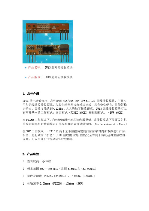
产品名称:ZW13超外差接收模块产品型号:ZW13超外差接收模块1.总体介绍ZW13是一款低价格、高性能的ASK/OOK(ON-OFF Keyed)无线接收模块,主要应用与无线遥控接收领域。
与其它超外差接收模块比较,具有价格便宜,性能好稳定特点。
灵敏度能达到-112dBm ,大大增加了接收距离。
ZW13无线接收模块可以有两种基本的工作模式:固定模式(FIXED MODE)和扫频模式。
(SWP MODE)在FIXED工作模式下,和传统的超外差式接收器类似,该接收模式下需要发射机的发射频率相对精确稳定石英晶振和声表面滤波SAW。
(Surface Acoustic Wave)在SWP工作模式下,ZW13以高于基带数据传输的扫频频率对内部本振进行扫频,相当于更有效的“扩宽”了RF接收的带宽,性能完全等同于传统超再生接收器。
因此,可以用廉价的免调谐LC发射机。
2.产品特性l 性价比高、小体积l 频率范围300—440 MHz(常用315MHz与433.92MHz)l 接收灵敏度-110dBm(315MHz),-112dBm(433MHz)l 传输速率2.5kbps (FIXED),10kbps (SWP)l 低功耗:3.7mA(315MHz,完全工作)4.6mA(433.92MHz,完全工作)l RF天线辐射非常低l 标准的CMOS接口数据输出3.应用领域l 遥控键盘l 远距离 RFIDl 遥控扇/灯/门l 防盗报警主机4.引脚排布及尺寸5.引脚描述6.额定参数7.工作参数8.产品订购9.注意事项l 正确接入直流电源,电源电压必须在工作范围之间。
l 天线位置对模块接收效果亦有影响,可以把天线直接焊ANT接口,亦可通过ANT的插针系统连接后再接到天线,安装时,天线尽可能伸直并且垂直于地面,远离屏蔽体,高压,及干扰源的地方。
l 与主机配套使用,一定要考虑主机是否对ZW13有干扰。
1.总体介绍ZW13是一款低价格、高性能的ASK/OOK(ON-OFF Keyed)无线接收模块,主要应用与无线遥控接收领域。