MAX1627ESA中文资料
MAX1600中文资料

MAX157AMJA -55°C to +125°C MAX157BMJA -55°C to +125°C MAX159ACUA 0°C to +70°C MAX159BCUA 0°C to +70°C MAX159ACPA 0°C to +70°C MAX159BCPA 0°C to +70°C MAX159AEUA -40°C to +85°C MAX159BEUA -40°C to +85°C MAX159AEPA MAX159BEPA MAX159AMJA MAX159BMJA -40°C to +85°C -40°C to +85°C -55°C to +125°C -55°C to +125°C
Mቤተ መጻሕፍቲ ባይዱX157/MAX159
Ordering Information
PART TEMP. RANGE 0°C to +70°C 0°C to +70°C 0°C to +70°C 0°C to +70°C -40°C to +85°C -40°C to +85°C -40°C to +85°C -40°C to +85°C PINPACKAGE 8 µMAX 8 µMAX 8 Plastic DIP 8 Plastic DIP 8 µMAX 8 µMAX 8 Plastic DIP 8 Plastic DIP 8 CERDIP* 8 CERDIP* 8 µMAX 8 µMAX 8 Plastic DIP 8 Plastic DIP 8 µMAX 8 µMAX 8 Plastic DIP 8 Plastic DIP 8 CERDIP* 8 CERDIP* INL (LSB) ±0.5 ±1 ±0.5 ±1 ±0.5 ±1 ±0.5 ±1 ±0.5 ±1 ±0.5 ±1 ±0.5 ±1 ±0.5 ±1 ±0.5 ±1 ±0.5 ±1
max680esa芯片参数资料(免费)
The MAX864/MAX865 are also recommended for new designs. The MAX864 operates at up to 200kHz and uses smaller capacitors. The MAX865 comes in the smaller µMAX package.
PIN-PACKAGE 8 Plastic DIP 8 Narrow SO Dice 8 Plastic DIP 8 Narrow SO 8 CERDIP 14 Plastic DIP 14 Plastic DIP
_________Typical Operating Circuits
+5V
4.7µF 4.7µF GND
C1+ VCC
MAX680 C1-
V+
C1+
V-
C2- GND
+5V
FOUR PINS REQUIRED (MAX681 ONLY)
VCC V+
MAX681 V-
GND
GND +5V to ±10V CONVERTER
4.7µF +10V
-10V 4.7µF
GND
+10V
-10V GND
________________________________________________________________ Maxim Integrated Products 1
IL- = 10mA, IL+ = 0mA, V+ = 10V
19-0896; Rev 1; 7/96
+5V to ±10V Voltage Converters
MAX1771ESA+中文资料
MAX1771
Ordering Information
PART MAX1771CPA MAX1771CSA MAX1771C/D MAX1771EPA MAX1771ESA MAX1771MJA TEMP RANGE 0°C to +70°C 0°C to +70°C 0°C to +70°C -40°C to +85°C -40°C to +85°C -55°C to +125°C PIN-PACKAGE 8 Plastic DIP 8 SO Dice* 8 Plastic DIP 8 SO 8 CERDIP**
ELECTRICAL CHARACTERISTICS
(V+ = 5V, ILOAD = 0mA, TA = TMIN to TMAX, unless otherwise noted. Typical values are at TA = +25°C.) PARAMETER Input Voltage Range Minimum Start-Up Voltage Supply Current Standby Current Output Voltage (Note 1) Output Voltage Line Regulation (Note 2) Output Voltage Load Regulation (Note 2) Maximum Switch On-Time Minimum Switch Off-Time Efficiency tON(max) tOFF(min) V+ = 5V, VOUT = 12V, ILOAD = 500mA, Circuit of Figure 2a MAX1771C Reference Voltage VREF IREF = 0µA MAX1771E MAX1771M REF Load Regulation REF Line Regulation FB Trip Point Voltage VFB 0µA ≤ IREF ≤ 100µA 3V ≤ V+ ≤ 16.5V MAX1771C MAX1771E MAX1771M 1.4700 1.4625 1.4550 MAX1771C/E MAX1771M 1.4700 1.4625 1.4550 V+ = 16.5V, SHDN = 0V (normal operation) V+ = 10V, SHDN ≥ 1.6V (shutdown) V+ = 16.5V, SHDN ≥ 1.6V (shutdown) V+ = 2V to 12V, over full load range, Circuit of Figure 2a V+ = 5V to 7V, VOUT = 12V ILOAD = 700mA, Circuit of Figure 2a V+ = 6V, VOUT = 12V, ILOAD = 0mA to 500mA, Circuit of Figure 2a 12 1.8 11.52 SYMBOL CONDITIONS MAX1771 (internal feedback resistors) MAX1771C/E (external resistors) MAX1771MJA (external resistors) MIN 2.0 3.0 3.1 1.8 85 2 4 12.0 5 12.48 TYP MAX 12.5 16.5 16.5 2.0 110 5 V µA µA V mV/V V UNITS
超米特电子有限公司产品说明书

1US Headquarters TEL +(1) 781-935-4850FAX +(1) 781-933-4318 • Europe TEL +(44) 1628 404000FAX +(44) 1628 404090Asia Pacific TEL +(852) 2 428 8008FAX +(852) 2 423 8253South America TEL +(55) 11 3917 1099FAX +(55) 11 3917 0817Superior elongation and tensilestrength help to prevent tearing in use due to mishandling. Typical properties for CHO-SEAL 1310 and 1273 materi-al are shown on pages 33 and 32respectively.High Shielding PerformanceCHO-SEAL 1310 material provides more than 80 dB of shielding effectiv-ness from 100 MHz to 10 GHz, while CHO-SEAL 1273 material provides more than 100 dB.Low Volume ResistivityBoth materials have exceptionally low volume resistivity, which makes them well suited for grounding appli-cations in which a flexible electrical contact is needed.Low Compression GasketSpacer gaskets are typicallydesigned to function under low deflec-tion forces. Chomerics uses design tools such as Finite Element Analysis (FEA) to accurately predict compres-sion-deflection behavior of various cross section options. Refer to page16.LCP Plastic SpacerLiquid crystal polymer (LCP)spacers, including those made with Vectra A130 material, provide aCHO-SEAL ®1310 or 1273Conductive ElastomersWith EMI spacer gaskets, shielding and grounding are provided by Chomerics’CHO-SEAL 1310 and 1273 conductive elastomers, specifi-cally formulated for custom shape molded parts. They provide excellent shielding and isolation against electro-magnetic interference (EMI), or act as a low impedance ground path between PCB traces and shielding media. Physically tough, these elas-tomers minimize the risk of gasket damage, in contrast to thin-walled extrusions or unsupported molded gaskets.Silicone-based CHO-SEAL 1310and 1273 materials offer excellent resistance to compression set over a wide temperature range, resulting in years of continuous service. CHO-SEAL 1310 material is filled with silver-plated-glass particles, while 1273 utilizes silver-plated-copper filler to provide higher levels of EMI shielding effectiveness.EMI Spacer GasketsThe unique design of Chomerics’EMI spacer gaskets features a thin plastic retainer frame onto which a conductive elastomer is molded. The elastomer can be located inside or outside the retainer frame, as well as on its top and bottom surface. EMI spacer gaskets provide a newapproach to designing EMI gaskets into handheld electronics such as dig-ital cellular phones. Board-to-board spacing is custom designed to fit broad application needs. Customized cross sections and spacer shapes allow for very low closure forcerequirements and a perfect fit in any design or device.Robotic InstallationSpacer gaskets can be installed quickly by robotic application. Integral locater pins in the plastic spacer help ensure accuratepositioning in both manual and pick-and-place assembly. Benefits include faster assembly and lower labor costs.The integrated conductive elastomer/plastic spacer gasket is a low cost,easily installed system for providing EMI shielding and grounding in small electronic enclosures.Figure 1Single Piece EMI Gasket/Locator PinsCHO-SEAL 1310 or 1273 Conductive Elastomer (Inside)Plastic Spacer Around Outsideor InsideApplications for EMI Spacer GasketsThe spacer gasket concept is especially suited to digital and dual board telephone handsets or other handheld electronic devices. It provides a low impedance path between peripheral ground traces on printed circuit boards and components such as:•the conductive coating on a plastic housing•another printed circuit board •the keypad assemblyTypical applications for EMI spacer gaskets include:•Digital cellular, handyphone and personal communications services (PCS) handsets •PCMCIA cards•Global Positioning Systems (GPS)•Radio receivers•Other handheld electronics, e.g.,personal digital assistants (PDAs)•Replacements for metal EMI shield-ing “fences” on printedcircuit boards in wireless tele-communications devicesstable platform for direct, highprecision molding of conductive elas-tomers. The Vectra A130 material described in Table 1 has excellent heat deflection temperature character-istics (489°F, 254°C). For weight con-siderations, the LCP has aspecific gravity of only 1.61. This plas-tic is also 100% recyclable.Typical EMI Spacer Gasket Design ParametersThe EMI spacer gasket concept can be considered using the design parameters shown in Table 2. Some typical spacer gasket profiles are shown below.Figure 2Typical Spacer Gasket Profiles3US Headquarters TEL +(1) 781-935-4850FAX +(1) 781-933-4318 • Europe TEL +(44) 1628 404000FAX +(44) 1628 404090Asia Pacific TEL +(852) 2 428 8008FAX +(852) 2 423 8253South America TEL +(55) 11 3917 1099FAX +(55) 11 3917 0817Finite Element AnalysisChomerics, a division of the Parker Hannifin Corporation’s Seal Group, is the headquarters of Parker Seal’s Elastomer Simulation Group. This unit specializes in elastomer finite element analysis (FEA) using MARC K6 series software as a foundation for FEA capability.Benefits of FEA include:•Quickly optimizing elastomer gasket designs•Allowing accurate predictions of alternate elastomer design concepts •Eliminating extensive trial and error prototype evaluationTypical use of FEA in EMI spacer gasket designs is to evaluate the force vs. deflection requirements of alternate designs.For example, onespacer design features a continuous bead of con-ductive elastomer molded onto a plastic spacer. An alternative designemploys an “interrupted bead,” where the interrup-tions (gaps left on the plastic frame) are sized to maintain the requiredlevel of EMI shielding. Figure 4illustrates these alternative designs.Gasket DeflectionFigure 5 compares the effect of continuous and interrupted elastomer gasket designs in terms of the force required to deflect the conductive elastomer. This actual cellular handset application required a spacer gasket with interrupted bead to meet desired deflection forces.Chomerics Designand Application ServicesChomerics will custom design a spacer for your application. Advice,analysis and design assistance will be provided by Chomerics Applications and Design engineers at no additional fee. Contact Chomerics directlyat the locations listed at the bottom of the page.Figure 3FEA Example of an EMISpacer Gasket Cross SectionFigure 4Continuous (top) and InterruptedElastomer GasketsFigure 5Typical Spacer Gasket Deflection。
MAX1619中文资料
ELECTRICAL CHARACTERISTICS
(VCC = +3.3V, TA = 0°C to +85°C, configuration byte = XCh, unless otherwise noted.)
PARAMETER
CONDITIONS
MIN TYP MAX UNITS
ADC AND POWER SUPPLY
Stresses beyond those listed under “Absolute Maximum Ratings” may cause permanent damage to the device. These are stress ratings only, and functional operation of the device at these or any other conditions beyond those indicated in the operational sections of the specifications is not implied. Exposure to absolute maximum rating conditions for extended periods may affect device reliability.
The MAX1619 is nearly identical to the popular MAX1617A, with the additional feature of an overtemperature alarm output (OVERT) that responds to the remote temperature; this is optimal for fan control.
MAX3072EASA中文资料
Continuous Power Dissipation (TA = +70°C) 8-Pin SO (derate 5.88mW/°C above +70°C) .................471mW 8-Pin Plastic DIP (derate 9.09mW/°C above +70°C) .....727mW 14-Pin SO (derate 8.33mW/°C above +70°C) ...............667mW 14-Pin Plastic DIP (derate 10.0mW/°C above +70°C) ...800mW
H/F, TXP, RXP)......................................................-0.3V to +6V Driver Input Voltage (DI)...........................................-0.3V to +6V Driver Output Voltage (Z, Y, A, B) .............................-8V to +13V Receiver Input Voltage (A, B)....................................-8V to +13V Receiver Input Voltage
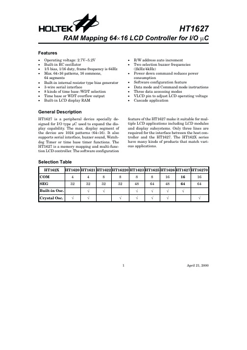
HT1627中文资料
T 2 10 T 3 11
(0 ,0 )
61 S E G 32 60 S E G 31
59 S E G 30 58 S E G 29
T 4 12 C O M 0 13
57 S E G 28 56 S E G 27
C O M 1 14 C O M 2 15
55 S E G 26 54 S E G 25
Y
-112.03 -112.03 -112.03 -112.03 -112.03 -112.03 -112.03 -112.03 -112.03 -112.03 -112.03 -112.03 -112.03 -112.03 -111.82
9.83 -93.20 -81.22 -74.59 -62.60 -55.97 -43.99 -37.36 -25.37 -18.74 -6.76 -0.13 11.86 18.49 30.47 37.10 49.09
· R/W address auto increment · Two selection buzzer frequencies
(2kHz/4kHz) · Power down command reduces power
consumption · Software configuration feature · Data mode and Command mode instructions · Three data accessing modes · VLCD pin to adjust LCD operating voltage · Cascade application
64 segments · Built-in internal resistor type bias generator · 3-wire serial interface · 8 kinds of time base /WDT selection · Time base or WDT overflow output · Built-in LCD display RAM
香Sizes(High Efficiency Power Amplifier)高效功率放大器用户手册
ii
Contents
Suggestions for Safety ................................................................................................ i Electrical Safety.............................................................................................................. i Transportation Safety ..................................................................................................... i Environmental Regulations ............................................................................................. i Safe Use Precautions ..................................................................................................... i Manual Labels and Information...................................................................................... ii
MAXTRAC 系列产品部件清单说明书

REF.NO.PART NO.DESCRIPTIONREF.NO.PART NO.DESCRIPTIONMAXTRAC 50/100 AND 820 SERIES202680223M05Shield, PA, VHF &UHF 202680223M05Shield, PA, 800 MHz 210980131M01Connector, antenna 222680124L03Heatsink, UHF &VHF 222680124L02Heatsink, 800 MHz 230980255E01Connector, power240310943M10Taptite Screw (M3 x 8); 8 used 250380271L01Machine Screw (M4 x 17); 2 used 260380043L01Taptite Screw (M3 x 10); 2 used 270400131974Washer; 2 used281580076M01Housing, accessory connector 297580918T02Pad, shock insulating; 5 used 300400002636Washer, int loc313280014N02Gasket, accessory connector 321380276L02Escutcheon, 2 frequencyNON-REFERENCED ITEMS:HLN5184B Switchboard 3380017N14Nameplate10380270L01Front Mounting Screws; 2 used 21580129L01Control Head Housing 33680144M01Control Knob 45080085D02Speaker54280253L01Speaker Retainer; 4 used 60310945A11Plastic Screw; 9 used 73880272L02Push Button; 2 used 84380273L01Push Button Spacer 97580200L01Keypad102900129883Wire Wrap; 2 used 110780037M01Bracket, switch board 122780128L04Chassis Frame 131580953T01Cover, VCO shield 142680038M03Shield, chassis RF150310943M09Taptite Screw (M3 x 6); 12 used 161580127L01Cover, housing; 2 used 171580124M01Cover, logic shield180310943R55Taptite Screw (M3 x 8, flathead); 4 used190310943R04Taptite Screw (M2.5 x 8, flathead); 2 usedREF.NO.PART NO.DESCRIPTIONREF.NO.PART NO.DESCRIPTIONMAXTRAC 300 AND 840 SERIES232680223M05Shield, PA, VHF&UHF232680223M05Shield, PA, 800 MHz240980131M01Connector, antenna252680124L03Heatsink, UHF &VHF252680124L02Heatsink, 800 MHz260980255E01Connector, power270310943M10Taptite Screw (M3 x 3); 8 used280380271L01Machine Screw (M4 x 27); 2 used290380043L01Taptite Screw (M3 x 10); 2 used300400131974Washer; 2 used313280039M01Gasket321580076M01Housing, accessory connector337580918T02Pad, shock insulating; 5 used340400002636Washer, int loc353280014N02Gasket, accessory connector361380277L01Escutcheon (16 freq. models)NON-REFERENCED ITEMS:HLN5184B Switchboard3380017N14NameplateNOTE: The part number for the speaker lead assembly,including connector P10 and two lugs, is 0180747T30.10380270L01Front Mounting Screws; 2 used 21580129L01Control Head Housing33680144M01Control Knob45080085D02Speaker54280253L01Speaker Retainer; 4 used 60310945A11Plastic Screw; 9 used73880272L02Push Button(6 freq. models); 3 used(16 freq. models); 5 used 84380274L01Push Button Spacer (1 x 2) 94380275L01Push Button Spacer (1 x 3) 107580201L01Keypad113880077N01Button Plug; 2 used123280907T01Gasket (6 freq. models only); 2 used 132900129883Wire Wrap; 2 used140780037M01Bracket Switch Board152780128L04Chassis Frame161580953T01Cover, VCO shield172680038M03Shield, chassis, RF180310943M09Taptite Screw (M3 x 6); 12 used 191580127L01Cover, housing; 2 used 201580124M01Cover, logic shield210310943R55Taptite Screw (M3 x 8, flathead);4 used220310943R04Taptite Screw (M2.5 x 8, flathead);2 usedMICROPHONESHSN4019B HMN1035CMOUNTING HARDWARE HLN4426AIGNITION SWITCH CABLEAccessories, Antennas ANTENNA ADAPTERHAD4008AHAD4006AVHF ANTENNASHAD4010ARAD4002ARA HAD4013AVHF ANTENNAHAE4003ARAE4022ARAUHF ANTENNAS800 MHZ ANTENNASRAF4011ARLRRA4933ASERVICE TOOLSRLN4008B RSX4043A6680163F010180357A57Service Aids, Manuals SERVICE AIDSHMN1035CHLN4426AHSN4019BHKN9327AEmergency Alarm 3dB, roof top w/14 ft. cable (890-960 MHz)3dB, roof top w/22 ft. cable 1/4 Wave, roof top (136-144 MHz)1/4 Wave, roof top (144-152 MHz)1/4 Wave, roof top (150.8-162 MHz)1/4 Wave, roof top (162-174 MHz)3dB, roof top (136-174 MHz)1/4 Wave, roof top (403-430 MHz)1/4 Wave, roof top (450-470 MHz)1/4 Wave, roof top (470-512 MHz)3.5dB, roof top (406-420 MHz)3.5dB, roof top (450-470 MHz)3.5dB, roof top (470-495 MHz)3.5dB, roof top (494-512 MHz)1/4 Wave Base Loaded Antenna 1/4 Wave Base Loaded Antenna 1/4 Wave Base Loaded Antenna HMN3000BHLN9330BHPN4002B HAE4013A。
Maxstar 161 S 电缆焊接机说明书
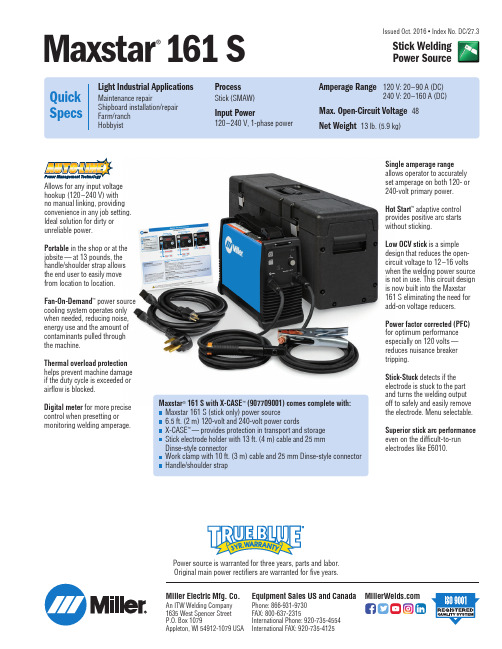
Issued Oct. 2016 • Index No. DC/27.3Single amperage range allows operator to accurately set amperage on both 120- or 240-volt primary power.Hot Start ™adaptive control provides positive arc starts without sticking.Low OCV stick is a simple design that reduces the open-circuit voltage to 12–16 volts when the welding power source is not in use. This circuit design is now built into the Maxstar 161 S eliminating the need for add-on voltage reducers.Power factor corrected (PFC)for optimum performance especially on 120 volts —reduces nuisance breaker tripping.Stick-Stuck detects if the electrode is stuck to the part and turns the welding output off to safely and easily remove the electrode. Menu selectable.Superior stick arc performance even on the difficult-to-run electrodes like E6010.Maxstar ®161 S with X-CASE ™(907709001) comes complete with:Maxstar 161 S (stick only) power source6.5 ft. (2 m) 120-volt and 240-volt power cordsX-CASE ™—provides protection in transport and storage Stick electrode holder with 13 ft. (4 m) cable and 25 mm Dinse-style connectorWork clamp with 10 ft. (3 m) cable and 25 mm Dinse-style connector Handle/shoulder strapPower source is warranted for three years, parts and labor.Original main power rectifiers are warranted for five years.Allows for any input voltage hookup (120–240 V) with no manual linking, providing convenience in any job setting.Ideal solution for dirty or unreliable power.Portable in the shop or at the jobsite —at 13 pounds, the handle/shoulder strap allows the end user to easily move from location to location.Fan-On-Demand ™power source cooling system operates only when needed, reducing noise,energy use and the amount of contaminants pulled through the machine.Thermal overload protection helps prevent machine damage if the duty cycle is exceeded or airflow is blocked.Digital meter for more precise control when presetting or monitoring welding amperage.Maxstar ®161SStick Welding Power SourceMiller Electric Mfg. Co.An ITW Welding Company 1635 West Spencer Street P.O. Box 1079Appleton, WI 54912-1079 USAEquipment Sales US and Canada Phone: 866-931-9730FAX: 800-637-2315International Phone: 920-735-4554International FAX: 920-735-4125Power Source and Options Stock No.DescriptionQty.PriceMaxstar ®161 S (only)907709Includes electrode holder, work clamp, and 120-volt and 240-volt power cords Maxstar ®161 S with X-CASE ™907709001Includes 907709 plus X-CASE ™Accessories X-CASE ™(only)301429Carrying case for Maxstar 161Date:Total Quoted Price:Ordering InformationControl PanelCertified by Canadian Standards Association to both the Canadian and U.S. Standards.1. Power Switch2.Menu Button3. Positive Weld Output Receptacle4.Ready Light5.Amperage Adjustment Control6.Negative Weld Output Receptacle*Sense voltage for stick.©2016 Miller Electric Mfg. Co.Distributed by:。
MEMORY存储芯片MAX1626ESA+T中文规格书
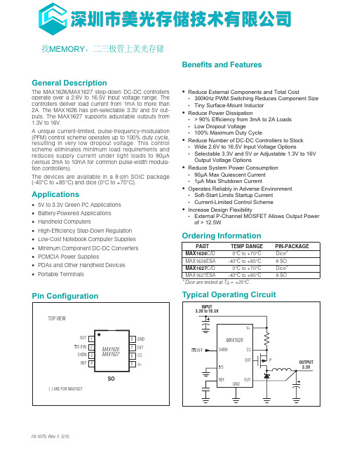
General DescriptionThe MAX1626/MAX1627 step-down DC-DC controllersoperate over a 2.6V to 16.5V input voltage range. Thecontrollers deliver load current from 1mA to more than2A. The MAX1626 has pin-selectable 3.3V and 5V out-puts. The MAX1627 supports adjustable outputs from1.3V to 16V.A unique current-limited, pulse-frequency-modulation(PFM) control scheme operates up to 100% duty cycle,resulting in very low dropout voltage. This controlscheme eliminates minimum load requirements andreduces supply current under light loads to 90µA(versus 2mA to 10mA for common pulse-width modula-tion controllers).The devices are available in a 8-pin SOIC package(-40°C to +85°C) and dice (0°C to +70°C).Applications•5V to 3.3V Green PC Applications•Battery-Powered Applications•Handheld Computers•High-Efficiency Step-Down Regulation•Low-Cost Notebook Computer Supplies•Minimum Component DC-DC Converters•PCMCIA Power Supplies•PDAs and Other Handheld Devices•Portable TerminalsBenefits and Features •Reduce External Components and Total Cost •300KHz PWM Switching Reduces Component Size •Tiny Surface-Mount Inductor •Reduce Power Dissipation •> 90% Efficiency from 3mA to 2A Loads •Low Dropout Voltage •100% Maximum Duty Cycle •Reduce Number of DC-DC Controllers to Stock •Wide 2.6V to 16.5V Input Voltage Options •Selectable 3.3V and 5V or Adjustable 1.3V to 16V Output Voltage Options •Reduce System Power Consumption •90µA Max Quiescent Current •1µA Max Shutdown Current •Operates Reliably in Adverse Environment •Soft-Start Limits Startup Current •Current-Limited Control Scheme •Increase Design Flexibility •External P-Channel MOSFET Allows Output Power of > 12.5WPin ConfigurationTypical Operating Circuit 19-1075; Rev 1; 5/15找MEMORY 、二三极管上美光存储MAX1626/MAX16275V/3.3V or Adjustable,100% Duty-Cycle, High-Efficiency,Step-Down DC-DC Controllers Maxim Integrated | 2Electrical CharacteristicsStresses beyond those listed under “Absolute Maximum Ratings” may cause permanent damage to the device. These are stress ratings only, and functional operation of the device at these or any other conditions beyond those indicated in the operational sections of the specifications is not implied. Exposure to absolute maximum rating conditions for extended periods may affect device reliability.Supply Voltage, V+ to GND.......................................-0.3V, +17VOUT, FB, 3/5, SHDN, REF, CS, EXT to GND...-0.3V, (V+ + 0.3V)Maximum Current at REF (I REF )..........................................15mAMaximum Current at EXT (I EXT )..........................................50mAContinuous Power Dissipation (T A = +70°C)SO (derate 5.88mW/°C above +70°C)..........................471mW Operating Temperature Range MAX1626ESA/MAX1627ESA............................-40°C to +85°C Storage Temperature Range.............................-65°C to +160°C Lead Temperature (soldering, 10sec).............................+300°C。
MAX3071EASA中文资料

Stresses beyond those listed under “Absolute Maximum Ratings” may cause permanent damage to the device. These are stress ratings only, and functional operation of the device at these or any other conditions beyond those indicated in the operational sections of the specifications is not implied. Exposure to absolute maximum rating conditions for extended periods may affect device reliability.
-40°C to +85°C 8 SO -40°C to +125°C 8 Plastic DIP
MAX3071EASA
-40°C to +125°C 8 SO
Ordering Information continued at end of data sheet.
Selector Guide, Pin Configurations, and Typical Operating Circuits appear at end of data sheet.
MAX3070E–MAX3079E
元器件交易网
19-2668; Rev 1; 1/03
+3.3V, ±15kV ESD-Protected, Fail-Safe, Hot-Swap, RS-485/RS-422 Transceivers
ZXMN6A07FTA中文资料(Diodes)中文数据手册「EasyDatasheet - 矽搜」

V ID = 250μA, V DS = V GS Ω VGS = 10V, I D = -1.8A
VGS = 4.5V, I D = -1.3A S VDS = 15V, I D = 1.8A V TJ = +25°C, I S = 0.45A, V GS = 0V ns TJ = +25°C, I F = 1.8A, nC di / dt = 100A/μs的
4. Automotive productsare AEC-Q101 qualified and are PPAP capable. Automotive, AEC-Q101 and standard productsare electrically and thermally the same, except where specified.
7. For a device surface mounted on FR4 PCB measured at t ≤5 secs. 8. Repetitive rating 25mm x 25mm FR4 PCB, D=0.02 pulse width=300μs- pulse current limited by maximum junction temperate 9. Thermal resistance from junction to solder-point (at the end of the drain lead).
标识信息
7N6 YM
7N6 =产品型号标识代码
芯片中文手册,看全文,戳
ZXMN6A07F
最大额定值
(@T A = + 25℃,除非另有说明.)
漏源电压 门源电压
特有
连续漏电流
MAX3088ESA+中文资料

MAX3062EEKA中文资料

DC ELECTRICAL CHARACTERISTICS
(VCC = +5V ±5%, TA = TMIN to TMAX, unless otherwise noted. Typical values are at VCC = +5V and TA = +25°C.) (Notes 1, 2)
PARAMETER DRIVER Differential Driver Output (No Load)
The MAX3060E features slew-rate-limited drivers that minimize EMI and reduce reflections caused by improperly terminated cables, allowing error-free data transmission up to 115kbps. The MAX3061E, also slewrate limited, transmits up to 500kbps. The MAX3062E driver is not slew-rate limited, allowing transmit speeds up to 20Mbps. All transmitter outputs are protected to ±15kV using the Human Body Model.
8-Pin SOT23 (derate 8.9mW/°C above +70°C)............714mW
Operating Temperature Range MAX306_EE_ _ ................................................-40°C to +85°C
Maxcell称重显示器使用说明书

.................................. 37
1
Maxcell
2-3-12 RS485 ID 输入 (选配功能)
............................................. 38
命令格式说明 ...................................................................................................................... 39
2-3-9 RS232 一般或简易输出重量 6 位或 7 位选择
..................... 35
2-3-10 RTC 时间调整
............................................................... 36
2-3-11 调整打印时年月日或日月年显示方式
2-3-3 输出格式选择
.................................................................... 29
2-3-4 传送方式设定
.................................................................... 30
使用前之准备工作
一. 请将本机放置于稳固且平坦之桌面上使用,勿放于摇动或振动之台架上。 二. 避免将本机放置于温度变化过大或空气流动剧烈之场所,如日光直射或冷气机之出风口。 三. 请使用独立之电源插座,以避免其它电器用品干扰。 四. 打开电源时,秤盘上请勿放置任何东西。 五. 产品使用时,秤物之重心须位于秤盘之中心点,且秤物不超出秤盘范围,以确保其准确度。 六. 使用本机前,请先温机 15 ~ 20 分钟。 七. 请注意当低电源警示之符号( )闪烁时,则表示须再行充电。 八. 如对本产品有任何建议,请不吝指正。
MAX3077EESA中文资料

The MAX3072E/MAX3075E/MAX3078E are intended for half-duplex communications, and the MAX3070E/ MAX3071E/MAX3073E/MAX3074E/MAX3076E/MAX307 7E are intended for full-duplex communications. The MAX3079E is selectable for half-duplex or full-duplex operation. It also features independently programmable receiver and transmitter output phase through separate pins.
MAX266中文数据手册

MAX266中文数据手册MAX266/265中文数据手册By Hi_Cracker @whu引脚电阻可编程通用高效滤波器-----MAX266/265General Description和MAX265是高效的容滤波器,专门设计用于需要高精度滤波的应用MAX266场合。
内置了两个独立的滤波模块,可以配置成低通,高通,带通,带阻,全通滤波器。
中心频率或者截止频率的控制需要外接电阻以及6 Pin-Strapped 的输入特性来编程实现,然而,Q值仅用电阻连接实现。
各种各样类型的滤波器都可以实现(巴特沃斯,切比雪夫,椭圆滤波器等等)。
内部集成了两个运算放大器。
MAX265可以将中心/截止频率可以最高调到40Khz,然而,MAX266,通过使用一个低范围的fclk/fo比例系数,可以将fos 调到140Khz。
4MHZ系统时钟,可以通过一个晶振或是额外的源获得。
滤波器的操作电压为从±2.37v到±6.3v或者+5V的单电源供电。
Application:声纳电子设备Anti-Aliasing 滤波器数字信号处理震动音频分析远程通信测试仪器Features滤波器参数设置软件化256bit的频率控制字电阻调整Q值和fo140Khz频率调节范围±5V或者单电源﹢5V操作电压Introduction每个MAX266/265都包含的两个可配置滤波器模块已经显示在数据手册前面的功能框图上。
fclk/fo编程输入(F0-F5)被两个滤波模块共用,然而,每个部分的fo仍然受到各自外接电阻的独立调节。
各个模块的的Q值也是受到各自的外接电阻的独立调节的。
MAX266使用比MAX265更低范围的取样比率(fclk/fo),这样就可以产生更高的信号带宽以及fo的可编程范围。
降低fclk/fo产生的影响主要就是比MAX265的滤波器参数的连续性稍微差了一些,但是这些不同可以通过使用图23所示的图形或是美信得滤波器软件来补偿。
MAX490EESA+资料
Supply Control
Voltage (VCC) Input Voltage
.(.–R—..E.–..,..D..E..)........................................-.0....5..V...t.o...(.V..C...C...+...0...152VV)
♦ For Low-Voltage Applications: MAX3483E/MAX3485E/MAX3486E/MAX3488E/ MAX3490E/MAX3491E: +3.3V Powered, ±15kV ESD-Protected, 12Mbps, Slew-Rate-Limited, True RS-485/RS-422 Transceivers
General Description
The MAX481E, MAX483E, MAX485E, MAX487E– MAX491E, and MAX1487E are low-power transceivers for RS-485 and RS-422 communications in harsh environments. Each driver output and receiver input is protected against ±15kV electro-static discharge (ESD) shocks, without latchup. These parts contain one driver and one receiver. The MAX483E, MAX487E, MAX488E, and MAX489E feature reduced slew-rate drivers that minimize EMI and reduce reflections caused by improperly terminated cables, thus allowing error-free data transmission up to 250kbps. The driver slew rates of the MAX481E, MAX485E, MAX490E, MAX491E, and MAX1487E are not limited, allowing them to transmit up to 2.5Mbps.
- 1、下载文档前请自行甄别文档内容的完整性,平台不提供额外的编辑、内容补充、找答案等附加服务。
- 2、"仅部分预览"的文档,不可在线预览部分如存在完整性等问题,可反馈申请退款(可完整预览的文档不适用该条件!)。
- 3、如文档侵犯您的权益,请联系客服反馈,我们会尽快为您处理(人工客服工作时间:9:00-18:30)。
SHDN 3 REF 4
MAX1626 MAX1627
6 5
SO
( ) ARE FOR MAX1627
________________________________________________________________ Maxim Integrated Products
1
For free samples & the latest literature: , or phone 1-800-998-8800
元器件交易网
19-1075; Rev 0; 6/96
NUAL KIT MA ATION SHEET A EVtable, 100% Duty-Cycle, High-Efficiency, Step-Down DC-DC Controllers
ELECTRICAL CHARACTERISTICS
(V+ = +3V to +16.5V, SHDN = 3/5 = 0V, TA = 0°C to +85°C, unless otherwise noted.) PARAMETER Input Voltage Range Supply Current into V+ Undervoltage Lockout Output Voltage OUT Input Current FB Threshold Voltage FB Leakage Current CS Input Current CS Threshold Voltage SHDN Input Voltage High SHDN Input Voltage Low SHDN Input Current 3/5 Input Voltage High 3/5 Input Voltage Low 3/5 Leakage Current EXT Resistance Minimum EXT Off Time EXT Duty-Cycle Limit Line Regulation Load Regulation Reference Voltage REF Load Regulation REF Line Regulation VREF 6.0V < V+ < 12.0V, ILOAD = 1A 30mA < ILOAD < 2.0A, V+ = 8V ILOAD = 0µA 0µA ≤ IREF ≤ 100µA V+ = 3V to 16.5V, ILOAD = 0µA 1.27 3/5 = 0V or V+ V+ = 5V Output forced to 0V Output in regulation 8 1.5 100 5 15 1.30 4 10 1.33 10 100 10 10 2.0 12 2.5 SHDN = 0V or V+ V+ - 0.5 0.5 ±1 VCS VOUT IOUT Circuit of Figure 1, 3/5 = V+ (Note 1) Circuit of Figure 1, 3/5 = 0V (Note 1) MAX1626, 3/5 = V+, output forced to 5V MAX1627, includes hysteresis MAX1627 4.85 3.20 24 1.27 0 0 85 1.6 0.4 ±1 100 SYMBOL V+ I+ Operating, no load V+ = SHDN = 16.5V (shutdown) 2.7 5.00 3.30 37 1.30 CONDITIONS MIN 3.0 70 TYP MAX 16.5 90 1 2.8 5.15 3.40 50 1.33 35 10 115 UNITS V µA V V µA V nA µA mV V V µA V V µA Ω µs % mV/V mV/A V mV µV/V
________________________Applications
PCMCIA Power Supplies Personal Digital Assistants Hand-Held Computers Portable Terminals Low-Cost Notebook Computer Supplies 5V to 3.3V Green PC Applications High-Efficiency Step-Down Regulation Minimum-Component DC-DC Converters Battery-Powered Applications
____________________________Features
o Low Dropout Voltage o 100% Maximum Duty Cycle o Soft-Start Limits Start-Up Current o Efficiency >90% (3mA to 2A Loads) o Output Power >12.5W o 90µA Max Quiescent Current o 1µA Max Shutdown Current o Up to 300kHz Switching Frequency o 16.5V Max Input Voltage o Output Voltage: 5V/3.3V (MAX1626) Adjustable (MAX1627) o Current-Limited Control Scheme
MAX1626/MAX1627
______________Ordering Information
PART MAX1626C/D MAX1626ESA MAX1627C/D MAX1627ESA TEMP. RANGE 0°C to +70°C -40°C to +85°C 0°C to +70°C -40°C to +85°C PIN-PACKAGE Dice* 8 SO Dice* 8 SO
元器件交易网
5V/3.3V or Adjustable, 100% Duty-Cycle, High-Efficiency, Step-Down DC-DC Controllers MAX1626/MAX1627
ABSOLUTE MAXIMUM RATINGS
Supply Voltage, V+ to GND.......................................-0.3V, +17V OUT, FB, 3/5, SHDN, REF, CS, EXT to GND ...-0.3V, (V+ + 0.3V) Maximum Current at REF (IREF) ..........................................15mA Maximum Current at EXT (IEXT) ..........................................50mA Continuous Power Dissipation (TA = +70°C) SO (derate 5.88mW/°C above +70°C) ..........................471mW Operating Temperature Range MAX1626ESA/MAX1627ESA ............................-40°C to +85°C Storage Temperature Range .............................-65°C to +160°C Lead Temperature (soldering, 10sec) .............................+300°C
_______________General Description
The MAX1626/MAX1627 step-down DC-DC switching controllers provide high efficiency over loads ranging from 1mA to more than 2A. A unique current-limited, pulse-frequency-modulated (PFM) control scheme operates with up to a 100% duty cycle, resulting in very low dropout voltages. This control scheme eliminates minimum load requirements and reduces the supply current under light loads to 90µA (versus 2mA to 10mA for common pulse-width modulation controllers). These step-down controllers drive an external P-channel MOSFET, allowing design flexibility for applications to 12W or higher. Soft-start reduces current surges during start-up. A high switching frequency (up to 300kHz) and operation in continuous-conduction mode allow the use of tiny surface-mount inductors. Output capacitor requirements are also reduced, minimizing PC board area and system costs. The output voltage is preset at 5V or 3.3V for the MAX1626 and adjustable for the MAX1627. Input voltages can be up to 16.5V. The MAX1626/MAX1627 are functional upgrades for the MAX1649/MAX1651.