熔盐反应制备TiC涂层碳纤维
熔盐氯化法生产四氯化钛工艺流程

熔盐氯化法生产四氯化钛工艺流程下载温馨提示:该文档是我店铺精心编制而成,希望大家下载以后,能够帮助大家解决实际的问题。
文档下载后可定制随意修改,请根据实际需要进行相应的调整和使用,谢谢!并且,本店铺为大家提供各种各样类型的实用资料,如教育随笔、日记赏析、句子摘抄、古诗大全、经典美文、话题作文、工作总结、词语解析、文案摘录、其他资料等等,如想了解不同资料格式和写法,敬请关注!Download tips: This document is carefully compiled by theeditor.I hope that after you download them,they can help yousolve practical problems. The document can be customized andmodified after downloading,please adjust and use it according toactual needs, thank you!In addition, our shop provides you with various types ofpractical materials,such as educational essays, diaryappreciation,sentence excerpts,ancient poems,classic articles,topic composition,work summary,word parsing,copy excerpts,other materials and so on,want to know different data formats andwriting methods,please pay attention!熔盐氯化法生产四氯化钛的工艺流程详解四氯化钛,化学式为TiCl4,是一种重要的化工原料,广泛应用于钛金属冶炼、涂料、塑料和染料等行业。
210875198_石墨表面TaC_涂层的熔盐法制备及表征

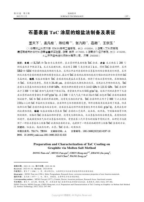
第52卷第2期表面技术2023年2月SURFACE TECHNOLOGY·297·石墨表面TaC涂层的熔盐法制备及表征董天下1,孟凡桂1,陈红梅2,3,张九阳4,高超4,王宗玉4(1.中南林业科技大学 材料科学与工程学院,长沙 410004;2.湖南人文科技学院 精细陶瓷与粉体材料湖南省重点实验室,湖南 娄底 417000;3.湖南涉外经济学院,长沙 410205;4.山东天岳先进科技股份有限公司,济南 250000)摘要:目的以K2TaF7和Ta粉为主要原料,在石墨材料表面制备TaC涂层。
方法反应物在1 200 ℃的熔盐体系中保温3 h,反应生成碳化物,经后续2 300 ℃真空保温1 h后,得到TaC涂层材料。
采用XRD和SEM对涂层的组成结构进行表征,采用拉开法对涂层的和石墨基体的结合强度进行测量,采用纳米压痕对涂层的硬度和弹性模量进表征,最后对TaC涂层的抗腐蚀性能进行模拟测试评估和实际的SiC 长晶测试。
结果熔盐法制备的TaC涂层连续地覆盖在石墨表面,保持了原始石墨的形貌,其物相组成为TaC,呈现出亮黄色,厚度为20~40 μm,涂层的晶粒无择优取向生长,呈现出无序堆积的状态。
TaC 涂层与石墨基体的结合强度为9.49 MPa,硬度和弹性模量分别为14.42 GPa和123.32 GPa。
TaC涂层样品于2 300 ℃的SiC腐蚀气氛环境下保温3 h,质量损失率仅为0.01 g/(m2·h),远低于同测试条件下无涂层石墨样品的质量损失率4.67 g/(m2·h)。
在2 300 ℃氩气气氛下保温3 h的SiC粉包埋TaC涂层的接触腐蚀试验中,SiC和TaC涂层的界面清晰,没有发生相互的扩散。
TaC涂层部件应用于2 000 ℃以上保温150 h以上的SiC单晶的生长制备后,涂层部件总体形貌保持完整,部件边缘棱角区域出现了脱落,但其他部位的TaC涂层仍和基体结合良好,涂层在长晶过程中的质量损失率约为0.41 g/(m2·h),表现出良好的抗腐蚀性能。
熔盐电化学转化二氧化碳制备碳材料的研究进展

第50卷第10期 辽 宁 化 工 Vol.50,No. 10 2021年10月 Liaoning Chemical Industry October,2021熔盐电化学转化二氧化碳制备碳材料的研究进展王 鹏(东北石油大学,黑龙江 大庆 163318)摘 要: 温室气体CO2的大量排放导致了众多的环境问题,因此寻找先进的CO2铺集转化技术迫在眉睫。
近年来,熔盐电化学一步法还原CO2制备碳材料技术,揭示了减少CO2排放的潜在解决方案。
利用熔盐电化学还原CO2具有以下优点:高选择性、高效率、低污染以及实现碳中和的可能性等。
重点介绍不同形貌碳产物的合成及应用。
根据改变合成条件,可以高效地获得碳纳米管、碳纳米洋葱和碳球等高附加值纳米碳结构。
对合成参数进行了比较,并对所得碳材料的应用作了简要概述。
此外,还对该技术的前景进行了讨论。
关 键 词:高温熔盐; 二氧化碳; 电化学转化; 碳纳米材料中图分类号:O613.71 文献标识码: A 文章编号: 1004-0935(2021)10-1495-04自工业革命以来,由于人为排放,导致大气中二氧化碳浓度急剧上升,WMO最新的《温室气体公报》指出,2019年大气中温室气体含量创历史新高,预计全球温室气体排放量近十年还会不断增加,到2030年都无法达到峰值[1]。
将温室气体CO2转化为有高附加值的化学燃料和功能材料,既有利于能量储存,又有利于CO2减排,实现碳中和的能源循环[2]。
到目前为止,已经提出了许多方法,如光催化还原法[3]、催化氢化法[4]和电化学还原法[5],来有效利用CO2合成高附加值碳材料。
在CO2捕集转化方面,科研工作者提出了许多方法,例如,在水溶液中电化学还原CO2为碳燃 料[6]。
但由于CO2在水中溶解度较差、析氢反应剧烈、对催化剂的要求复杂,这一方法仍具有挑战 性[7]。
高温熔融具有离子迁移速率快、导电性好和稳定性高等优点,与水溶液相比,提高了反应的选择性和CO2转化效率[8]。
熔盐法制备mxene

熔盐法制备mxene简介:MXene是一种新型的二维材料,具有优异的导电性和机械性能,广泛应用于能源储存、电子器件和催化等领域。
熔盐法是一种常用的MXene制备方法,本文将介绍熔盐法制备MXene的原理和步骤。
一、熔盐法的原理熔盐法是指将金属氧化物或金属胁迫物溶解在盐熔剂中,经高温处理后,与盐熔剂发生反应生成MXene的方法。
二、实验步骤1. 材料准备为制备MXene,我们需要准备适量的金属氧化物或金属胁迫物(如二氧化钛、氯化铝)、盐熔剂(如氯化铝和氯化钠混合物)以及其他辅助试剂。
2. 混合溶解将金属氧化物或金属胁迫物与盐熔剂混合,加入适量的溶剂,如水、乙醇等,使其充分溶解,并形成均匀的溶液。
3. 煅烧处理将混合溶液置于高温炉中进行煅烧处理。
通过控制煅烧温度和时间,使金属氧化物或金属胁迫物与盐熔剂发生反应生成MXene。
4. 过滤和洗涤将煅烧后的样品通过滤纸过滤,得到固体沉淀。
为去除盐熔剂和其他杂质,用适量的溶剂反复洗涤沉淀,直至洗涤液无色为止。
5. 干燥将洗涤后的沉淀置于真空烘箱中干燥,得到纯净的MXene样品。
三、实验条件的影响1. 煅烧温度和时间:不同温度和时间对MXene的结构和性能有不同的影响。
过高的温度可能导致MXene结构破坏,而过低的温度则可能导致MXene未能完全形成。
2. 盐熔剂种类和比例:盐熔剂的种类和比例会影响MXene的产率和结晶度。
不同的盐熔剂对金属氧化物或金属胁迫物的溶解能力不同,从而影响MXene的制备效果。
3. 溶剂选择:溶剂的选择会影响MXene的分散性和纯度。
一般情况下,较优质的溶剂可提高MXene的分散性,使其在电子器件等领域中更好地应用。
四、MXene的应用前景MXene作为一种新型材料,具有巨大的应用潜力。
它在能源储存领域,如超级电容器和锂离子电池方面,表现出了卓越的性能;在电子器件领域,如柔性电子和光电器件方面,具有很高的导电性和机械性能;此外,在催化和传感等领域也有广泛的应用。
熔盐法制备氮化碳原理

熔盐法制备氮化碳的原理主要基于熔盐作为反应介质和盐模板,促进反应物的扩散和加速反应进程。
在较低的合成温度和较短的反应时间下,通过熔盐法可以形成具有特殊结构的产物。
具体的制备过程通常是以二氰二胺、三聚氰胺或二氨基马来腈等物质作为氮源和碳源,与熔盐介质(如LiBr-KCl)反应,生成氮化碳粉体。
这种制备方法具
有绿色、高效的特点,并且可以通过调控反应条件如盐料比、反应温度和保温时间等来调控氮化碳的微观形貌结构和性能。
熔盐法的发展及原理

熔盐在高温下可能发生爆炸或 泄漏等安全事故。
改进与优化建议
加强设备防腐
采用耐腐蚀材料或涂层等措施,减少设备腐 蚀。
降低能耗
采用先进的换热技术和节能设备,降低熔盐 法的能耗。
优化操作参数
通过实验和模拟等方法,优化温度、压力等 参数,提高操作稳定性。
加强安全措施
制定严格的安全操作规程,加强设备监测和 维护,降低安全风险。
低成本
熔盐法使用的材料相对便宜,且在高 温下具有较好的化学稳定性,降低了 生产成本。
可再生能源利用
熔盐法可以与太阳能、地热能等可再 生能源结合使用,提高能源利用效率。
缺点分析
高能耗
熔盐法需要高温加热和冷却, 能耗较高。
设备腐蚀
熔盐中的氯离子等成分会对设 备造成腐蚀,影响设备使用寿 命。
操作复杂
熔盐法需要严格控制温度和压 力等参数,操作难度较大。
https://
2023 WORK SUMMARY
THANKS
感谢观看
REPORTING
实现熔盐法的绿色化、智能化和高效化是未来的 重要发展方向。
PART 03
熔盐法的应用案例
熔盐法在材料制备中的应用
制备陶瓷材料
熔盐法可用于制备高性能陶瓷材料,如氮化硅陶瓷、碳化 硅陶瓷等,这些陶瓷材料具有高硬度、高耐磨性和高温稳 定性等优点。
制备金属材料
熔盐法可用于制备金属材料,如钛、锆、铪等,这些金属 在高温下具有良好的抗腐蚀性和机械性能。
太阳能利用
熔盐法可用于太阳能利用领域,如太 阳能电池板的制造和太阳能热发电等 ,这些过程需要高效地吸收和转化太 阳能。
PART 04
熔盐法的优缺点分析
优点分析
熔盐氯化法生产四氯化钛工艺

熔盐氯化法生产四氯化钛工艺第一部分:熔盐氯化基础理论知识1、熔盐氯化的原理熔盐氯化是指高钛渣在熔盐介质中,在还原剂碳存在的条件下,氯气将高钛渣中的氧化物氯化成氯化物的过程。
其主要化学反应为:Q g CO g TiCl g Cl s C s TiO C ++−−−→−++︒-)()()(2)()(2485070022 Q g CO g TiCl g Cl s C s TiO C++−−−→−++︒-)(2)()(2)(2)(485070022Q g CO g TiCl g Cl g CO s TiO C ++−−−→−++︒-)(2)()(2)(2)(2485070022 熔盐氯化工艺作为氯化法生产钛白粉的氯化工序。
应用氧化工序尾气或纯氯气为主要原料进行熔盐氯化生产。
当氯气以一定速度通入氯化炉熔盐层时会强烈地搅动熔盐。
同时入炉氯气被加热并分散在熔盐介质中。
并使从熔盐界面上部加入到炉内的高钛渣和石油焦固体混合料充分地分散在熔盐中,并在表面张力的作用下使这些固体粉状混合料保持在分散的熔盐介质中许多小气泡的表面,实际上氯化反应正是在这些无数小气泡表面进行的。
熔盐氯化反应时ΣTi 在熔盐中的含量在1~3%,碳含量控制在2~7%,反应生成的气体产物进入到气泡中,使气泡长大、上升,最终冲出熔盐界面后破裂进入到气相中去,液态产物则留在熔盐中最后随废盐一同排出。
高钛渣熔盐氯化反应为放热反应,因此提高氯化炉产能的同时应有效地控制好温度,做好系统的热平衡。
2、熔盐氯化的特点优点:①对含钙镁高的钛原料具有良好的适应性。
②熔盐氯化流程简单,炉料不需制团和焦化。
③熔盐氯化的耗碳量和废气量比非熔盐氯化少,有利于四氯化钛的冷凝。
④熔盐中的氯化钠、氯化钾能与三氯化铁、三氯化铝形成稳定的氯络合物,因而熔盐有净化杂质的作用。
缺点:①大量的废盐回收困难。
②炉衬的寿命短。
3、影响熔盐氯化的主要因素①熔盐组成熔盐的物料化学性质是影响氯化过程的重要因素。
一种炭纤维增强纳米孔炭隔热复合材料的制备方法[发明专利]
![一种炭纤维增强纳米孔炭隔热复合材料的制备方法[发明专利]](https://img.taocdn.com/s3/m/64c4d91e9e3143323868939b.png)
专利名称:一种炭纤维增强纳米孔炭隔热复合材料的制备方法专利类型:发明专利
发明人:冯坚,冯军宗,张海明,李良军,姜勇刚
申请号:CN201711322146.8
申请日:20171212
公开号:CN107892582A
公开日:
20180410
专利内容由知识产权出版社提供
摘要:本发明公开了一种炭纤维增强纳米孔炭隔热复合材料的制备方法,目的是提供一种周期短、安全可靠、炭化过程体积收缩小的炭纤维增强纳米孔炭隔热复合材料的制备方法。
技术方案是以酚类和醛类为反应单体,甲醇为溶剂,六次甲基四胺为催化剂,氯化锌作为熔盐起到致孔剂和支撑的作用,炭纤维作为增强体,首先经过原料混合制成酚醛溶胶,用酚醛溶胶浸渍炭纤维预制件,溶胶变成凝胶后,在室温下老化后炭化裂解,最后水洗除盐、常压干燥得到炭纤维增强纳米孔炭隔热复合材料。
本发明周期短、安全可靠、炭化过程体积收缩小,采用本发明制备的材料密度小,耐温达2000℃,且不会出现开裂的现象,有利于制备异形构件。
申请人:中国人民解放军国防科技大学
地址:410003 湖南省长沙市开福区德雅路109号
国籍:CN
代理机构:长沙中科启明知识产权代理事务所(普通合伙)
代理人:任合明
更多信息请下载全文后查看。
碳纤维制备技术的研究进展

碳纤维制备技术的研究进展碳纤维是一种高性能复合材料,具有轻质、高强、高模量、耐高温、耐腐蚀等优点。
因此,碳纤维被广泛应用于航空、航天、汽车、体育器材、新能源等领域。
碳纤维制备技术的研究发展是实现碳纤维产业化的重要基础,本文将分析碳纤维制备技术的研究进展。
一、传统碳纤维制备技术传统的碳纤维制备技术包括射线裂解法、拉延法、吐丝法、气相溶胶凝胶法、催化化学气相沉积法等。
这些制备技术存在的问题主要有两个方面,一是能耗大,投资成本高;二是所得碳纤维性能难以控制,存在方向性差、纤维直径变化大等缺陷。
二、新型碳纤维制备技术2.1 高温炭化法高温炭化法是指将高分子材料在高温条件下进行热解,生成高纯度的碳化物,再经过拉伸、热处理等步骤制得碳纤维。
该制备技术由于成本低、生产工艺简单、碳纤维性能可控等优点,被广泛关注。
目前,该技术在美国商业应用已经实现。
2.2 微波炭化法微波炭化法是指利用微波辐射烧结材料,高速形成碳化物,再通过拉伸等步骤制备碳纤维。
该方法具有微波辐射穿透、速度快、成本低、冲击能小等优点,可控性较高。
该技术在国内外研究者的共同努力下,取得了一定的研究进展。
2.3 溶胶凝胶法溶胶凝胶法是指将有机/无机前驱体通过水热反应或溶胶凝胶技术,制备精细、均匀的纳米颗粒,再经高温炭化处理制得碳纤维。
该技术由于反应条件温和、产物纤维形成性能好,可控性强,所得碳纤维具有纤维直径小、方向性好等特点。
三、碳纤维的应用前景随着新材料技术的发展和碳纤维的优越性能,碳纤维在多个领域的应用已经到了广泛、深入的地步,其中航空、航天、汽车、体育器材、新能源等领域是碳纤维应用的主要方向。
比如,在航空航天领域,碳纤维被广泛应用于飞机、火箭、卫星等部分结构件中;在汽车领域,碳纤维被用于车身材料、制动系统、轮毂等部分零部件中。
可以预见,随着技术的不断进步,碳纤维的应用前景将会更加广阔。
结语:本文介绍了碳纤维制备技术的研究进展,分析了传统制备技术的缺陷,阐述了新型制备技术的优势和应用前景。
熔盐捕获CO2电化学制备高附加值碳材料研究进展

熔盐捕获CO2电化学制备高附加值碳材料研究进展目录一、内容概览 (2)二、熔盐捕获CO2技术概述 (3)1. CO2排放现状及危害 (4)2. 熔盐捕获CO2技术原理 (5)3. 熔盐捕获CO2技术流程 (6)三、电化学制备高附加值碳材料理论基础 (6)1. 电化学基本原理 (8)2. 碳材料制备的电化学方法 (8)3. 高附加值碳材料的性能及应用 (10)四、熔盐捕获CO2电化学制备碳材料的研究进展 (11)1. 研究现状 (12)2. 制备方法 (13)3. 影响因素分析 (14)4. 性能表征 (16)五、实验设计与结果分析 (17)1. 实验材料与方法 (19)2. 实验结果与讨论 (20)3. 性能评价与表征 (21)六、技术经济分析与前景展望 (22)1. 技术经济性分析 (23)2. 环境保护效益分析 (24)3. 市场前景展望 (25)七、结论与建议 (27)1. 研究结论 (28)2. 研究建议与展望 (29)一、内容概览本论文综述了熔盐捕获CO2电化学制备高附加值碳材料的研究进展。
随着全球气候变化问题日益严重,CO2的捕集与转化已成为科学研究的热点。
熔盐技术作为一种高效、环保的CO2捕获方法,受到了广泛关注。
通过将CO2溶解在熔盐中,利用电化学方法将其转化为高附加值碳材料,不仅可以实现CO2的资源化利用,还可以降低环境污染。
在熔盐捕获CO2的过程中,研究者们采用了不同的电化学方法,如电化学还原、电化学气浮等,以促进CO2的还原和碳材料的生成。
通过调控熔盐的组成、温度、压力等条件,可以优化CO2的捕获效率和碳材料的性能。
所得到的碳材料具有丰富的孔结构、高的比表面积和优异的电化学性能,可广泛应用于能源存储、催化反应、传感器等领域。
通过对熔盐捕获CO2电化学制备碳材料的机理进行深入研究,可以为开发高效、环保的CO2资源化利用技术提供理论依据。
熔盐捕获CO2电化学制备高附加值碳材料作为一种新兴的技术手段,具有广阔的应用前景和巨大的经济价值。
【国家自然科学基金】_碳纤维表面_基金支持热词逐年推荐_【万方软件创新助手】_20140801

107 108 109 110 111 112
tic涂层 tac涂层 rpc nio cvi cfrp
推荐指数 12 5 4 3 3 3 3 2 2 2 2 2 2 2 2 2 2 2 1 1 1 1 1 1 1 1 1 1 1 1 1 1 1 1 1 1 1 1 1 1 1 1 1 1 1 1 1 1 1 1 1 1
1 1 1 1 1 1 1 1 1 1 1 1 1 1 1 1 1 1 1 1 1 1 1 1 1 1 1 1 1
53 54 55 56 57 58 59 60 61 62 63 64 65 66 67 68 69 70 71 72 73 74 75 76 77 78 79 80 81 82 83 84 85 86 87 88 89 90 91 92 93 94 95 96 97 98 99 100 101 102 103 104 105 106
2009年 序号 1 2 3 4 5 6 7 8 9 10 11 12 13 14 15 16 17 18 19 20 21 22 23 24 25 26 27 28 29 30 31 32 33 34 35 36 37 38 39 40 41 42 43 44 45 46 47 48 49 50 51 52
科研热词 推荐指数 碳纤维 15 表面处理 4 氨气 4 纳米碳纤维 3 复合材料 3 化学气相沉积 3 聚丙烯腈纤维 2 水泥基 2 氨基 2 多巴胺 2 鱼骨式纳米碳纤维 1 非均相催化剂 1 陶瓷涂层 1 钯催化剂 1 钯 1 钛硅分子筛 1 过滤 1 载体效应 1 裂缝 1 表面种植 1 芳基硫醇 1 自愈合涂层 1 胆碱 1 聚酰亚胺 1 聚芳基乙炔 1 羟基磷灰石(hap) 1 羟乙基纤维素 1 结构 1 粘结性能 1 粘砂 1 等电点 1 稳定化 1 磺化 1 碳纳米片 1 碳纤维编织网 1 碳纤维电极 1 碳纤维增强碳复合材料 1 碳纤维/石墨基体 1 碳纤维/环氧复合材料界面 1 碳化硼 1 硅溶胶-凝胶 1 界面性能 1 电控离子分离 1 电化学传感器 1 生物相容性 1 玻璃基骨水泥 1 环己酮氨氧化 1 湿法纺丝 1 混合 1 液相 1 涂层 1 浮动催化 1
- 1、下载文档前请自行甄别文档内容的完整性,平台不提供额外的编辑、内容补充、找答案等附加服务。
- 2、"仅部分预览"的文档,不可在线预览部分如存在完整性等问题,可反馈申请退款(可完整预览的文档不适用该条件!)。
- 3、如文档侵犯您的权益,请联系客服反馈,我们会尽快为您处理(人工客服工作时间:9:00-18:30)。
Preparation of a titanium carbide coating on carbon fibre using a molten salt methodXuanke Li a,b,*,Zhijun Dong a ,Aidan Westwood b ,Andy Brown b ,Shaowei Zhang a,c ,Rik Brydson b ,Nan Li a ,Brian Rand baThe Hubei Province Key Laboratory of Ceramics and Refractories,Wuhan University of Science and Technology,Wuhan,Hubei 430081,PR China bInstitute for Materials Research,The University of Leeds,Leeds LS29JT ,United Kingdom cEngineering Materials,The University of Sheffield,Western Bank,Sheffield S102TN,United KingdomA R T I C L E I N F O Article history:Received 14August 2007Accepted 20November 2007Available online 2January 2008A B S T R A C TA method for preparing protective titanium carbide (TiC)coatings on carbon fibres has been developed using a molten salt synthesis method.The TiC coatings were formed on the sur-face of carbon fibres in a reaction medium consisting of Ti powder in a mixture of molten LiCl–KCl–KF salts under an argon atmosphere at 900and 950°C.The structure and morphol-ogy of the TiC coatings were characterized by XRD,SEM and energy dispersive X-ray (EDX)analyses.The coatings consisted of homogeneous single phase cubic TiC with thicknesses in the range of 60–800nm.Variation of the synthesis time and reaction mixture was found to significantly affect the thickness and integrity of the TiC coating although variation of the reaction temperature had little effect.The coating thickness was closely related to the com-position of the molten salts and to the molar ratio between the carbon fibre and titanium.Ó2007Elsevier Ltd.All rights reserved.1.IntroductionDespite their uniquely superior properties,the interface compatibility problems between carbon fibre and most matri-ces have limited the industrial application of carbon fibre reinforced metallic and ceramic matrix composites.More-over,the applications of carbon fibres for composite rein-forcement are also limited since carbon reacts with many metallic and ceramic matrix materials.Much effort is there-fore being expended in attempts to provide a refractory coat-ing on the surface of the carbon to shield carbon materials from reactive environments at elevated temperatures and to improve the carbon fibre–matrix interfacial properties [1–5].This approach is only partially successful since the thickness,homogeneity and integrity of coating on the carbon fibre sur-face is difficult to control.Titanium carbide (TiC)is one of the most important refractory metal carbides used as advanced ceramics for wear resistance and aerospace applications.This is primarily due to its high melting temperature (3067°C),high Young’s modu-lus (410–450GPa),high chemical stability and high Vickers hardness (28–35GPa)[6,7],which allow its use in cemented carbides,such as cermets,and oxidation resistant materials.Thin protective titanium nitride and carbide layers have been formed on the surface of carbon fibres [3,5]using a chemical vapour deposition method.However,Kerridge and Polyakov reported [8]that Li–LiCl and Ca–CaCl 2ionic–electronic melts could be used as a medium for the reaction of a mixture of carbon black and transition metals to synthesis the carbides of titanium,zirconium,niobium and tantalum at 800–1000°C over 5–10h under an argon atmosphere.The mol-ten salt synthesis (MSS)method offers a route for synthesis of0008-6223/$-see front matter Ó2007Elsevier Ltd.All rights reserved.doi:10.1016/j.carbon.2007.11.020*Corresponding author:Address:The Hubei Province Key Laboratory of Ceramics and Refractories,Wuhan University of Science and Technology,Wuhan,Hubei 430081,PR China.Fax:+862786551274.E-mail address:xkli8524@ (X.Li).C A R B O N46(2008)305–309a v a i l ab l e a t w w w.sc i e n c ed i re c t.c omj o u r n a l h o m e p a g e :w w w.e l s e v i e r.c o m /l o c a te /c a r b o ntransition metal carbides at low temperatures in relatively short times,since the molten salt acts effectively as the reac-tion medium.This approach also provides the possibility for the controllable preparation of TiC products with various morphologies such as coatings,particles and nanofibres.Like the chemical vapour deposition studies[3,5],this work also describes the preparation of a TiC coating on car-bonfibre but,in this case,a medium of molten salts is used for reaction of titanium powder with carbonfibre,derived from polyacrylonitrile(PAN),at900–950°C under an argon atmosphere.This approach avoids some of the problems with current syntheses of TiC,which often require very high tem-peratures,rigorous reagent handling or yield non-stoichiom-etric products,and enables formation of a TiC coating with high purity and controllable thickness on the surface of car-bonfibre.2.Experimental2.1.Preparation of a TiC coating on carbonfibresPAN-based Tenax carbonfibre bundles,dried after immersion in acetone for several hours to remove the sizing agent,were used as the carbon source for the synthesis of a TiC coating by reaction with titanium metal powder(99.5wt%purity,200 mesh size ex Sigma–Aldrich)in a molten salt mixture com-posed of KCl,LiCl and KF.The diameter of this carbonfibre is around6–8l m.The molar ratio of titanium to carbon in the molten salts was chosen to be either Ti/C=1/1.5or1/2.5.The carbonfibre bundle was placed in an alumina crucible and covered by the mixture of titanium and the salts,heat-treated at900or950°C for1–5h under aflowing argon atmosphere and then allowed to cool to room temperature.After cooling, the product in the crucible was boiled repeatedly in distilled water to dissolve the salts in order to retrieve the TiC-coated carbonfibres by decanting off the supernatant solution.The coated carbonfibres were then dried at100°C for2h.2.2.The characterization of TiC-coated carbonfibresThe phases present in the TiC-coated carbonfibres after mol-ten salt treatment were determined by XRD using Cu K a radi-ation.The surface morphology of the coated carbonfibres was investigated using a Carl Zeiss LEO1530field emission scanning electron microscope(FESEM).Their elemental com-positions were obtained using the energy dispersive X-ray (EDX)analyzer linked to this instrument.Thermogravimetric analysis(TGA)was performed on90mg samples of uncoated and coated carbonfibres produced from$1cm lengths of short carbonfibres.Samples were heated at5°C/min to 880°C and held for1h underflowing air at a rate of250ml/ min.3.Results and discussionAfter reaction in the molten salts using a molar ratio of Ti/ C=1/1.5,a golden colouredfibre product was obtained. Fig.1a illustrates the XRD pattern for thefibreproductFig.1–(a)XRD pattern of golden colouredfibres prepared from Tenax carbonfibre using a Ti/C molar ratio of1/1.5in molten salts at950°C for5h,and(b)an SEM image and corresponding EDX elemental maps of(c)titanium and(d)carbon in thefibre cross sections.306C A R B O N46(2008)305–309prepared using this molar ratio in the molten salts at 950°C for 5h.The five sharp peaks at 2h =35.91°,41.71°,60.45°,72.36°and 76.13°correspond to diffraction from the 111,200,220,311and 222crystal planes of a face-centered cubic TiC phase,respectively.The relative intensities of these five peaks are also consistent with those expected for bulk TiC.A broad peak is also observed at 2h =ca.26°(and possibly ca.43°also),which can be attributed to the PAN-based carbon fibre,indi-cating that the PAN-based fibres have not been completely transformed into TiC fibres.This implies that TiC forms a coating only on the surface of carbon fibres during the molten salt treatment.The typical cross-sectional morphology of these golden coloured carbon fibres is shown in Fig.1b.This reveals that the product consists of fibres and each fibre is composed of a shell and core.In order to determine the elemental compo-sition of the fibre,the cross section of coated fibre was char-acterized by EDX analysis.Fig.1c and d shows maps of the titanium (Ti K a )and carbon (C K a )elemental distributions,respectively,corresponding to the SEM image shown in Fig.1b.This reveals that the fibres contain both titanium and carbon which are mainly located in the shell and the core of fibres,respectively.This confirms that a TiC coating has been formed on the surface of the carbon fibre.The thickness of this TiC coating on the carbon fibres is estimated from SEM to be about 800nm.The coatings are homogeneous with a densified structure and a smooth surface composed of many polycrystalline grains.In order to reveal the influence of reaction time and Ti/C molar ratio on the thickness of the TiC coating formed on the surface of the carbon fibres,FESEM images of the product fibres produced at 950°C are shown in Fig.2a and b,after 5h reaction and in Fig.2c and d after 1h reaction.This shows that,after 5h and 1h,the TiC coating thicknesses on the product fibres are about 220and 65nm,respectively,confirm-ing that the thickness of the coating increases with reaction time.Very similar results were obtained following the corre-sponding reactions at 900°C and this suggests that there is no clear influence of reaction temperature in the range 900–950°C on the thickness of the coating.The thinly TiC-coated carbon fibres produced during the reactions for 1h show a smooth and crack-free surface and possess flexibility almost as high as that of the original uncoated carbon fibre.The 220nm coating thicknesses on the fibres shown in Fig.2a–b,produced with a Ti/C ratio of 1/2.5over 5h at 950°C,are still smaller than the 800nm thickness of the coating on the fibres shown in Fig.1b,and produced with a Ti/C ratio of 1/1.5over 5h at 950°C.This demonstrates that the thickness of the coating (as determined by SEM)increases not only with reac-tion time,but also with the molar ratio of titanium to carbon at 950°C.Both of these TiC-coated carbon fibre products are stiffer than the carbon fibre starting material and this can be attributed to the thickening effect of TiC coating formation.The dissolution of metals in molten salt is not well under-stood,but it has been suggested that transport reactions are allowed because metals dissociate to mobile cations and delo-calised electrons,a state which is considered to be intermedi-ate between ionic and metallic [8–10].Li et al.calculated [9]that Gibbs free energy change D G o ðT Þfor the reaction of Ti with graphite in the range of 298–1200K is givenbyFig.2–T ypical SEM images of the cross sections of TiC-coated carbon fibres prepared from Tenax carbon fibres using the molten salt method with a Ti/C molar ratio of 1/2.5at 950°C for (a,b)5h and (c,d)1h.C A R B O N46(2008)305–309307C ðgraphite ÞþTi ¼TiC ;D G o ðT Þ¼À184116:4þ10:60445ÂT ðJ =mol ÞThis result shows that titanium metal can react directly with graphite and form TiC,but due to some kinetic consider-ations,such as the contact area between titanium metal pow-der and carbon,it is difficult to form a densified TiC coating on the carbon surface.The molten salt mixture is believed to facilitate the dissolution and transport of the titanium and hence the formation of the TiC coating through diffusion of titanium cations from the molten salt to the surface of the carbon fibres with subsequent reaction.Therefore,it would seem that the concentration of titanium cations in the molten salt is important in determining the thickness of TiC coating.However,the exact mechanism of coating formation is still unclear.According to Pan et al.[10],the inclusion of K 2TiF 6in the molten salt mixture will be advantageous to the formation of titanium cations.Therefore,K 2TiF 6was added to the mol-ten salt mixture of KCl,LiCl and KF .The morphology of the TiC coating produced using the K 2TiF 6additive,with a Ti/C ra-tio of 1/2.5over 5h at 950°C,is shown in Fig.3a and b.In com-parison to the corresponding coating prepared without K 2TiF 6,shown in Fig.2a,the thickness of the TiC coating in-creases from about 220–480nm owing to the addition of K 2TiF 6.This suggests that the addition of K 2TiF 6does indeed increase the titanium cation concentration in molten salt,as expected.(In contrast,the effectiveness of the incorpora-tion of potassium fluoride in the molten salt mixture in order to enhance TiC formation,whether by promoting dissolution and transport of Ti metal or by improving the surface state of carbon fibres,is not clear).Fig.3a and b also shows some cracks,coating fragments and missing areas of coating,which suggest that the cracks are formed in the coating and that the coating then peels off the surface of the carbon fibre.As coating thickness in-creases,the coated carbon fibres become stiff and fragile with reduced flexibility.If the coating is too thick there is a possi-bility that cracks will develop at the coating-fibre interface,presumably due to the mismatch in thermal expansion coef-ficients between coating and core.Therefore,the control of TiC coating thickness and the influence of the coating thick-ness on the mechanical properties of the coated carbon fibre require investigation in further work.Finally,Fig.4shows the TGA curves of both uncoated and TiC-coated carbon fibres.The weight loss of the uncoated car-bon fibre sample commences at around 425°C,and the rate of weight loss increases markedly in the range 500–780°C.The weight loss of TiC-coated carbon fibre begins at around 645°C and in comparison to uncoated carbon fibres,this weight loss initiation temperature is increased by around 220°C.However,the rate of weight loss during subsequent oxidation is similar to that of the uncoated fibres.It can also be seen from Fig.4that the TiC-coated fibres show a slight weight gain at about 580°C,which can be attributed to the oxidation of the TiC coating.The relationship between the thickness of the TiC coating and mechanical properties and oxidation resistance is currently being investigated for TiC-coated carbon fibres.4.ConclusionsTiC-coated carbon fibres were successfully produced using a relatively low temperature molten salt method.A high qual-ity,crystalline TiC coating was produced on the surface of PAN-based carbon fibres.Analysis reveals that a thin,homo-geneous and crack-free TiC coating is formed on thesurfaceFig.3–T ypical SEM images of:(a)the surface and (b)the cross section of TiC-coated carbon fibres prepared from Tenax carbon fibres using the molten salt method at 950°C for 5h with K 2TiF 6additive and with a Ti/C molar ratio of1/2.5.308C A R B O N46(2008)305–309of carbonfibres.It is observed that the molten salt components,titanium/carbon molar ratio and the reaction time can all significantly affect the coating thickness and integrity of the TiC coating.However,variation of the reaction temperature between900and950°C had no clear effect on these parameters.Coated carbonfibres with a thickness of about65nm display goodflexibility but,as TiC coating thick-ness increases,the coatedfibres become stiff and fragile.This method offers possibilities for the synthesis of various transi-tion metal carbide coatings using MSS methods,and hence the use of carbide-coatedfibres for the reinforcement of metallic and ceramic composites.AcknowledgementsThe authors acknowledge thefinancial support of the Na-tional Natural Science Foundation of China(Grant No. 50672070)and Royal Society KC Wong Education Foundation.R E F E R E N C E S[1]Wang YQ,Zhou BL,Wang ZM.Oxidation protection of carbonfibers by coatings.Carbon1995;33(4):427–33.[2]Vincent H,Vincent C,Berthet MP,Bouix J,Gonzalez G.Boroncarbide formation from BCl3–CH4–H2mixtures on carbonsubstrates and in a carbon-fibre reinforced Al composite.Carbon1996;34(9):1041–55.[3]Hackl G,Gerhard H,Popovska N.Coating of carbon shortfibers with thin ceramic layers by chemical vapourdeposition.Thin Solid Films2006;513(1–2):217–22.[4]Sebo P,Stefanik P,Kavecky S,Ivan J.Influence of carbideforming elements(Ti,Zr)on the interface of coppermatrix-carbonfibre composite.Kovove Mater1999;37(6):367–76.[5]Vincent H,Vincent C,Berthet MP,Mourichoux H,Bouix J.Mechanical and chemical characteristics of carbon-fibersprotected with a carbide coating formed by reactivechemical-deposition.J Less Common Met1991;175(1):37–58.[6]Storms EK.The refractory carbides,refractory materialsseries,vol.2.New York:Academic Press;1967.p.82.[7]Pierson HO.Handbook of refractory carbides andnitrides.Westwood:Noyes Publications;1996.p.71.[8]Kerridge DH,Polyakov EG.Refractory metals in molten salts:their chemistry,electrochemistry,and technology.Dordrecht, Boston:Kluwer Academic;1998.p.81–6.[9]Li CH,Lu HB,Xiong WH,Chen X.Diamond and graphitecoated with polyalloys by an immersion method.Surf Coat Tech2003;150:163–9.[10]Pan W,Huang QL,Chen J,Cai J,Huang Y.Mechanism oftitanium deposition on Al2O3ceramic surface by molten salt reaction.Mater Lett1997;31:317–20.C A R B O N46(2008)305–309309。
