MP2615_r0.8_
安装指南:Compact 5000 I O 8 点安全灌入型数字输入模块说明书

安裝說明Compact 5000 I/O 8 點安全灌入型數位輸入模組目錄編號 5069-IB8S 、5069-IB8SK5069-IB8S 和 5069-IB8SK 模組是 8 點安全灌入型輸入模組。
這些模組在符合 SIL CL3 和 PLe 、Cat. 4 在內等要求的安全控制網絡上提供安全I/O ,依照 IEC 61508、IEC 61511、IEC 62061 和 ISO 13849-1 中所規定。
您可以將 Compact 5000™ I/O 安全模組作為具有 CompactGuardLogix®5380 控制器的本地和遠端 I/O ,以及具有 GuardLogix 5580 控制器的遠端I/O 模組。
5069-IB8SK 模組的功能與 5069-IB8S 模組相同,但也具有保形塗層,可在惡劣環境中加以保護。
使用 Studio 5000 Logix Designer® 軟體設定模組。
Compact GuardLogix 5380 和 GuardLogix 5580 控制器必須使用韌體版本 32.011 或更新版本,才能使用Compact 5000 I/O 安全模組。
Compact 5000 I/O 安全模組使用生產者/消費者通訊模型。
生產者/消費者通訊模型是模組與其他系統裝置之間的一種智慧型資料交換,其中的每一個模組都不用先被輪詢即產生資料。
關於如何使用 Compact 5000 I/O 模組的詳細資訊,請參閱其他資源(第12頁)中所列的出版品。
變更摘要主題頁次關於模組5安裝系統5安裝拆卸式端子座7安裝模組8安裝端蓋9拆卸式端子座配線9從拆卸式端子座中斷電線9使用束線帶10開啟系統電源10移除模組10規格11其他資源12主題頁數移除配線圖有關如何為模組接上電線的資訊,請參閱其他資源(第12頁)中所列的出版物N/ACompact 5000 I/O 8 點安全灌入型數位輸入模組ATTENTION:Read this document and the documents listed in the Additional Resources section about installation, configuration and operation of this equipment before you install, configure, operate ormaintain this product. Users are required to familiarize themselves with installation and wiring instructions in addition to requirements of all applicable codes, laws, and standards.Activities including installation, adjustments, putting into service, use, assembly, disassembly, and maintenance are required to be carried out by suitably trained personnel in accordance with applicable code of practice.If this equipment is used in a manner not specified by the manufacturer, the protection provided by the equipment may be impaired.注意:在安装、配置、操作和维护本产品前,请阅读本文档以及“其他资源”部分列出的有关设备安装、配置和操作的相应文档。
LM258中文资料_数据手册_参数

LM158, LM158A, LM258, LM258A LM358, LM358A, LM2904, LM2904V
SLOS068T – JUNE 1976 – REVISED APRIL 2015
Table of Contents
1 Features .................................................................. 1 2 Applications ........................................................... 1 3 Description ............................................................. 1 4 Revision History..................................................... 2 5 Pin Configuration and Functions ......................... 3 6 Specifications......................................................... 4
Brushless DC, High-Voltage, Low-Voltage, Permanent Magnet, and Stepper Motor • Oscilloscopes • TV: LCD and Digital • Temperature Sensors or Controllers Using Modbus • Weigh Scales
Device Information(1)
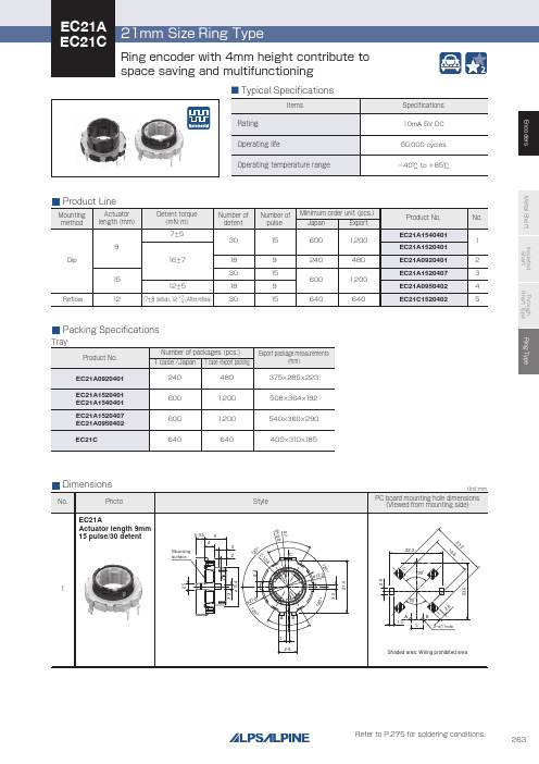
263系列金属螺杆尖耐抗电尖耐抗电尖通螺杆类型环形编码器说明书
Through shaft type
Horizontal
Horizontal
—
12/12
12/24 12/12
9/18 15/30
Ring type
— 15/30
Features
W
Dimensions (mm)
D
H
Operating temperature range
Operating life Automotive use Life cycle (availability)
300V AC for 1minute or 360V AC for 2s
300V AC for 1minute or 360V AC for 1s
—
7±5mN・m 12±5mN・m 16±7mN・m
—
17±8mN・m(Initial) 12+− 74mN・m(After reflow)
100N
Shaft configuration
1
Style
5-3.5 9
4 Mounting surface
3 2
120°
ø21.6
C ø12.2
AB 1
2-8
120°
0.7
2-10.4 120°
Unit:mm
PC board mounting hole dimensions (Viewed from mounting side)
22.3
3
˃˃
˃ $ ˃ $
˃˃
"# "#
EC21A Actuator length 15mm 9 pulse/18 detent
CiTRANS R845系列设备简介_V2.0

15
15
设备硬件
CiTRANS R845 防尘网位于风扇 单元左侧,由托架和低密度防尘网 构成。该防尘网采用自锁方式进行 固定,便于插拔 。
16
16
单盘简介
CiTRANS R845、CiTRANS R835E、CiTRANS R830E三款设备共用包 括路由控制盘、交叉时钟盘、各类接口盘、电源盘在内的组件
22
22
设备硬件
CiTRANS R830E业务单元配置说明表
单盘名称 10GE光接口盘(2路) 10GE光接口盘(1路) GE/FE混合接口盘(8路) FE光接口盘(8路) FE电接口盘(8路) STM1光接口盘(4路) 2M电接口盘(32路) 单盘缩号 XSK2 XSK3 MSP1 ESK3 ESK4 S1K3 E1K4 可配置槽位 SLOT 1、3、 4 备注 提供2路10GE光口 提供1路10GE光口 每个端口均可单独配置为GE光口、FE光口或FE电
CiTRANS R845/R835E/R830E 设备简介
烽火通信网络产出线 2013年2月28日
1
1
目录: 设备概述
系统架构 设备硬件 单盘简介
注意事项
端口MAC地址生成开关 RCUP1升级 SCUP1升级 温度和风扇
典型工程
大兴安岭 攀枝花
2 2
设备概述
3
3
设备概述
CiTRANS R845设备是烽火公司推出的高端IP/MPLS路由器产品,主要定位 于移动回传网的接入和汇聚层、多业务城域网的接入和汇聚层。 CiTRANS R845具备高速接口的线速转发能力、完善的QoS机制、运营级的 可靠性、丰富的业务处理能力、方便灵活的业务配置和管理和分组化的时间同步 技术,满足数据业务以及IP RAN业务对简介
MOONS ST驱动器的SCL 说明书
上海安浦鸣志自动化设备有限公司
ST 驱动器的 SCL 使用手册
目
ห้องสมุดไป่ตู้
录
简介... .................................................................................5 SCL 是什么? ................................................................................................................................................5 SCL 的详细资料 ............................................................................................................................................5 开始 ....................................................................................7 步骤一:安装软件 ........................................................................................................................................7 步骤二:用 ST Configurator 设置您的 ST 驱动器 .......... ..............................................
VCA2615PFBR,VCA2615RGZT,VCA2615RGZT,VCA2615RGZT,VCA2615RGZR,VCA2615RGZRG4, 规格书,Datasheet 资料

precautions. Failure to observe proper handling and installation procedures can cause damage.ESD damage can range from subtle performance degradation to complete device failure. Precision integrated circuits may be more susceptible to damage because very small parametric changes could cause the device not to meet its published specifications.Time(200ns/div)Figure 57. LNP Gain Change ResponseThe LNP also feeds a MUX, which accepts the LNP signal or can receive an external signal. When applying an external signal to the MUX (VCA IN), the signal should be biased to a common-mode voltage in the range of 1.85V to 3.15V. This biasing could be accomplished by using the 2.5V level of the V CM pin (19) of the VCA2615.To MUX(VGA IN)INVCMSource Impedance (Ω)30010020050040060070080090010006.0E−108.0E−101.0E−091.2E−091.4E−091.6E−091.8E−092.0E−09LNP Noise nV/√Hz Figure 61. Noise Figure for Active TerminationSource Impedance (Ω)3001002005004006007009001000800VCA NOISE =3.8nV √Hz,LNP GAIN =20dBLNP Noise nV/√Hz 6.0E−108.0E−101.0E−091.2E−091.4E−091.6E−091.8E−092.0E−09Figure 62. Noise Figure for ConventionalTerminationTime(400ns/div)Figure 64. Response to Step Change of V CNTLTime(400ns/div)Figure 65. Response to Ramp Change of V CNTL The exponential gain control characteristic is achieved through a piecewise approximation to a perfectly smooth exponential curve. Eight FETs, operated as variable resistors whose value is progressively 1/2 of the value of the adjacent parallel FET, are turned on progressively, or their value is lowered to create the exponential gain characteristic. This characteristic can be shown in the following way. An exponential such as y = e x increases in dimension by a constant ratio as the x dimension increases by a constant linear amount. In other words, for a constant (x1 − x2), the ratio e x1/e x2 remains the same. When FETs used as variable resistors are placed in parallel, the attenuation characteristic that is created behaves according to this same exponential characteristicTime(200ns/div)Figure 67. Before Overload (100mV PP Input)Time(200ns/div)Figure 68. Approaching Overload (120mV PP Input)POWER-DOWN MODES(5V) is applied to the VCA2615, the total power dissipation is typically 308mW. When the power is initially applied to the VCA2615 with both PDV and PDL pins at a logic low, the typical power dissipation will be 5mW. After the VCA2615 has been enabled, if the PDL line is low with the PDV line high, the typical power dissipation will be approximately 100mW. After the VCA2615 has been enabled, if the PDV line is low with the PDL line high, the typical power dissipation will be approximately 200mW.Time(200ns/div)Figure 69. Overload (240mV PP Input)Time(200ns/div)Figure 70. Extreme Overload (2V PP Input)PACKAGING INFORMATIONOrderable Device Status (1)Package Type Package Drawing Pins Package Qty Eco Plan (2)Lead/Ball Finish MSL Peak Temp (3)VCA2615PFBR ACTIVE TQFP PFB 481000Green (RoHS &no Sb/Br)CU NIPDAU Level-2-260C-1YEAR VCA2615PFBT ACTIVE TQFP PFB 48250Green (RoHS &no Sb/Br)CU NIPDAU Level-2-260C-1YEAR VCA2615RGZR ACTIVE VQFN RGZ 482500Green (RoHS &no Sb/Br)CU NIPDAU Level-3-260C-168HR VCA2615RGZRG4ACTIVE VQFN RGZ 482500Green (RoHS &no Sb/Br)CU NIPDAU Level-3-260C-168HR VCA2615RGZT ACTIVE VQFN RGZ 48250Green (RoHS &no Sb/Br)CU NIPDAU Level-3-260C-168HR VCA2615RGZTG4ACTIVEVQFNRGZ48250Green (RoHS &no Sb/Br)CU NIPDAULevel-3-260C-168HR(1)The marketing status values are defined as follows:ACTIVE:Product device recommended for new designs.LIFEBUY:TI has announced that the device will be discontinued,and a lifetime-buy period is in effect.NRND:Not recommended for new designs.Device is in production to support existing customers,but TI does not recommend using this part in a new design.PREVIEW:Device has been announced but is not in production.Samples may or may not be available.OBSOLETE:TI has discontinued the production of the device.(2)Eco Plan -The planned eco-friendly classification:Pb-Free (RoHS),Pb-Free (RoHS Exempt),or Green (RoHS &no Sb/Br)-please check /productcontent for the latest availability information and additional product content details.TBD:The Pb-Free/Green conversion plan has not been defined.Pb-Free (RoHS):TI's terms "Lead-Free"or "Pb-Free"mean semiconductor products that are compatible with the current RoHS requirements for all 6substances,including the requirement that lead not exceed 0.1%by weight in homogeneous materials.Where designed to be soldered at high temperatures,TI Pb-Free products are suitable for use in specified lead-free processes.Pb-Free (RoHS Exempt):This component has a RoHS exemption for either 1)lead-based flip-chip solder bumps used between the die and package,or 2)lead-based die adhesive used between the die and leadframe.The component is otherwise considered Pb-Free (RoHS compatible)as defined above.Green (RoHS &no Sb/Br):TI defines "Green"to mean Pb-Free (RoHS compatible),and free of Bromine (Br)and Antimony (Sb)based flame retardants (Br or Sb do not exceed 0.1%by weightin homogeneous material)(3)MSL,Peak Temp.--The Moisture Sensitivity Level rating according to the JEDEC industry standard classifications,and peak solder temperature.Important Information and Disclaimer:The information provided on this page represents TI's knowledge and belief as of the date that it is provided.TI bases its knowledge and belief on information provided by third parties,and makes no representation or warranty as to the accuracy of such information.Efforts are underway to better integrate information from third parties.TI has taken and continues to take reasonable steps to provide representative and accurate information but may not have conducted destructive testing or chemical analysis on incoming materials and chemicals.TI and TI suppliers consider certain information to be proprietary,and thus CAS numbers and other limited information may not be available for release.In no event shall TI's liability arising out of such information exceed the total purchase price of the TI part(s)at issue in this document sold by TI to Customer on an annual basis.PACKAGE OPTION ADDENDUM8-Dec-2009TAPE AND REEL INFORMATION*All dimensions are nominalDevicePackage Type Package Drawing Pins SPQReel Diameter (mm)Reel Width W1(mm)A0(mm)B0(mm)K0(mm)P1(mm)W (mm)Pin1Quadrant VCA2615PFBR TQFP PFB 481000330.016.49.69.6 1.512.016.0Q2VCA2615PFBT TQFP PFB 48250330.016.49.69.6 1.512.016.0Q2VCA2615RGZR VQFN RGZ 482500330.016.47.37.3 1.512.016.0Q2VCA2615RGZTVQFNRGZ48250180.016.47.37.31.512.016.0Q2*All dimensions are nominalDevice Package Type Package Drawing Pins SPQ Length(mm)Width(mm)Height(mm) VCA2615PFBR TQFP PFB481000367.0367.038.0 VCA2615PFBT TQFP PFB48250367.0367.038.0 VCA2615RGZR VQFN RGZ482500367.0367.038.0VCA2615RGZT VQFN RGZ48250210.0185.035.0IMPORTANT NOTICETexas Instruments Incorporated and its subsidiaries(TI)reserve the right to make corrections,enhancements,improvements and other changes to its semiconductor products and services per JESD46C and to discontinue any product or service per JESD48B.Buyers should obtain the latest relevant information before placing orders and should verify that such information is current and complete.All semiconductor products(also referred to herein as“components”)are sold subject to TI’s terms and conditions of sale supplied at the time of order acknowledgment.TI warrants performance of its components to the specifications applicable at the time of sale,in accordance with the warranty in TI’s terms and conditions of sale of semiconductor products.Testing and other quality control techniques are used to the extent TI deems necessary to support this warranty.Except where mandated by applicable law,testing of all parameters of each component is not necessarily performed.TI assumes no liability for applications assistance or the design of Buyers’products.Buyers are responsible for their products and applications using TI components.To minimize the risks associated with Buyers’products and applications,Buyers should provide adequate design and operating safeguards.TI does not warrant or represent that any license,either express or implied,is granted under any patent right,copyright,mask work right,or other intellectual property right relating to any combination,machine,or process in which TI components or services are rmation published by TI regarding third-party products or services does not constitute a license to use such products or services or a warranty or endorsement e of such information may require a license from a third party under the patents or other intellectual property of the third party,or a license from TI under the patents or other intellectual property of TI.Reproduction of significant portions of TI information in TI data books or data sheets is permissible only if reproduction is without alteration and is accompanied by all associated warranties,conditions,limitations,and notices.TI is not responsible or liable for such altered rmation of third parties may be subject to additional restrictions.Resale of TI components or services with statements different from or beyond the parameters stated by TI for that component or service voids all express and any implied warranties for the associated TI component or service and is an unfair and deceptive business practice. TI is not responsible or liable for any such statements.Buyer acknowledges and agrees that it is solely responsible for compliance with all legal,regulatory and safety-related requirements concerning its products,and any use of TI components in its applications,notwithstanding any applications-related information or support that may be provided by TI.Buyer represents and agrees that it has all the necessary expertise to create and implement safeguards which anticipate dangerous consequences of failures,monitor failures and their consequences,lessen the likelihood of failures that might cause harm and take appropriate remedial actions.Buyer will fully indemnify TI and its representatives against any damages arising out of the use of any TI components in safety-critical applications.In some cases,TI components may be promoted specifically to facilitate safety-related applications.With such components,TI’s goal is to help enable customers to design and create their own end-product solutions that meet applicable functional safety standards and requirements.Nonetheless,such components are subject to these terms.No TI components are authorized for use in FDA Class III(or similar life-critical medical equipment)unless authorized officers of the parties have executed a special agreement specifically governing such use.Only those TI components which TI has specifically designated as military grade or“enhanced plastic”are designed and intended for use in military/aerospace applications or environments.Buyer acknowledges and agrees that any military or aerospace use of TI components which have not been so designated is solely at the Buyer's risk,and that Buyer is solely responsible for compliance with all legal and regulatory requirements in connection with such use.TI has specifically designated certain components which meet ISO/TS16949requirements,mainly for automotive ponents which have not been so designated are neither designed nor intended for automotive use;and TI will not be responsible for any failure of such components to meet such requirements.Products ApplicationsAudio /audio Automotive and Transportation /automotiveAmplifiers Communications and Telecom /communicationsData Converters Computers and Peripherals /computersDLP®Products Consumer Electronics /consumer-appsDSP Energy and Lighting /energyClocks and Timers /clocks Industrial /industrialInterface Medical /medicalLogic Security /securityPower Mgmt Space,Avionics and Defense /space-avionics-defense Microcontrollers Video and Imaging /videoRFID OMAP Mobile Processors /omap TI E2E Community Wireless Connectivity /wirelessconnectivityMailing Address:Texas Instruments,Post Office Box655303,Dallas,Texas75265Copyright©2012,Texas Instruments Incorporated。
E4980A 精密 LCR 表用户指南
本手册中的警告(如下面的示例)介绍了潜在的危险操作。请务必遵守警告 中提及的操作细则。
在这种仪器中存在能导致死亡的危险电压。 在装卸、测试和调整这种仪器时需格外小心。
注
上述制造号中“x”显示的编号位置表示版本号。
示例程序
为了便于内部使用,客户将拥有个人使用、复制或修改本手册中示例程序的权利, 但这种权利不可转让。客户可根据自己的用途独自使用示例程序,但不得许可、租赁、 买卖或散布示例程序,也不得对其中的任何部分进行修改。
是德科技将不对示例程序的质量、性能或运行状况负责。是德科技不保证示 例 程序的运行不间断或无差错。示例程序按照原样提供。
不提供任何其他明示或暗示的担保。特别是,是德科技对用于特定目的的适销性和 适应性的暗示担保不承担责任。
独家补救
这里提供的补救指对买方唯一的独家补救。是德科技将不对任何直接、间接、特殊、 偶然或必然的损害负责,无论这些损害是基于合同、侵权还是任何其他法律理论。
5
协助
产品维护协议及其它客户协助协议适用于是德科技的产品。 如欲获得任何协助,请与最近的是德科技销售和服务处联系。本手册的背面提供了 这些销售和服务处的地址。
安全概述
当用户发现下列任何异常情况时,应立即终止操作并断开电源线。 维修仪器请与当地的是德科技销售代表或其授权的维修公司联系。如果不对仪器进行 维修而继续使用,则可能会给操作者带来失火或触电隐患。
- 仪器操作异常。 - 操作过程中,仪器发出异常噪音、异味、冒烟或电火花。 - 操作过程中,仪器产生高温或出现电击现象。 - 电源线、插头或仪器的插座受损。 - 外界物质或液体进入仪器。
Kistler 9101C 压电环形力传感器说明书

ForcePiezoelectric force sensorsPiezoelectric ring force transducers for tensile and compression forces from 20 kN to 700 kN9101C _003-473e -08.21Page 1/6© 2020 ... 2021 Kistler Group, Eulachstrasse 22, 8408 Winterthur, Switzerland. Kistler Group products are This information corresponds to the current state of knowledge. Kistler reserves the right to make technical changes. Liability for consequential damage resulting Types 9101C, 9102C,9103C, 9104C,9105C, 9106C, 9107CPiezoelectric force sensors, also known as piezoelectric ring force transducers, for precise measurement of tensile and com-pressive forces in highest resolution.The force sensors are thoroughly tested, but are delivered wit-hout calibration certificate and must be calibrated on site after installation.• Thoroughly tested, delivered without calibration certificate • Linearity including hysteresis ≤±1.5%• Extremely high stiffness • Very compact design • Extremely low threshold• Degree of protection: IP68, dependent on cable • Operating temperature range -40 ... 120°C • No aging, unlimited service lifeDescriptionThe 910x family is a piezoelectric (PE) sensor series for force measurement in the z-direction. The force to be measured is transmitted directly to the quartz element located within the sensor. When subjected to a mechanical load, quartz produces an electric charge that is proportional to that load. An outstan-ding property of quartz is the very low threshold, resulting in a high sensor sensitivity which is extremely linear over the entire measuring range. Thus the behaviour in a certain measuring range is practically identical for all PE sensors, independent of their size.This has three unique advantages:• Overload protection: Even very small forces can be measured with a sensor with a large measuring range, so that overload protection can be considered without loss of signal quality.• High stiffness: To achieve a construction that is as stiff as possible, a larger sensor can also be used without negatively impacting the quality of the measurement signal.• Grouping: Multiple sensors can simply be added together by electrically connecting them in parallel to a single charge amplifier. The output voltage is then proportional to the sum of all acting forces.ApplicationFor monitoring tasks, force sensors are required that can be easily installed in a machine structure. Robust design and re-liability in continuous operation as well as good repeatability of the measured values are further features of these sensors. The choice of a certain size depends on the installation space available on the one hand and on the force shunt ratio of the installation on the other hand.Application examples• Monitoring of press-in forces during assembly, testing, etc.• Monitoring of forces during punching and forming • Measurement of large forces in force shuntSensor MountingRing force transducers are generally used preloaded in a mounting structure.Types 9101C ... 9107CF zDetails about piezoelectric sensors and their installation can be found in the corresponding user's manual on our home-page /force.9101C _003-473e -08.21Page 2/6© 2020 ... 2021 Kistler Group, Eulachstrasse 22, 8408 Winterthur, SwitzerlandTel.+41522241111,****************,. Kistler Group products are This information corresponds to the current state of knowledge. Kistler reserves the right to make technical changes. Liability for consequential damage resulting Technical data--> to ensure the specifications, the sensors must be operated and tested with 20% preload Type9101C9102C 9103C 9104C 9105C 9106C 9107C Nominal force kN 2050100140190330700Load limit kN 2560120160210360770SensitivitypC/N -4.4 ±0.3Linearity incl. hysteresis %FSO ±1.5Repeatability %0.070.020.040.040.050.040.02Reproducibility %0.250.100.100.120.130.110.04Axial stiffness kN/m m 1.6 3.3 5.27.59.815.427.7Lateral stiffness 1)kN/m m 0.310.74 1.3 1.8 2.4 3.97.6Shear stiffness kN/m m 0.400.88 1.5 2.2 2.8 4.69.0Torsional stiffness Nm/°385 1 955 4 93510 26818 46947 184190 330Bending stiffnessNm/°388 2 016 5 18311 22820 82255 355216 950Maximum bending moment 2) (M z = 0), calc.N·m22862173796181 3184 229Temperature sensitivity change ±1.5 (-40°C ... 120°C, Tref = 25°C)%Operating temperature range °C -40 ... 120Insulation resistance (@23°C)W ≥ 5.1013Threshold N <0.01Capacitance pF17±233±452±570±693±6149±15303±20Sensor material Cover plate 1.4821 Coat 1.4542Connector typeKIAG 10-32 neg.Degree of protection (IEC 60529)IP check table on page 4Weightg7203670801573701)Resistantance of the sensor to shear and bending deformation. (Theoretical) assumption: The sensor is fixed at the bottom, the shear force acts at the top, so that the lever length is equal to the toal sensor height. 2)With a pretension of 50% of the nominal force9101C _003-473e -08.21Page 3/6© 2020 ... 2021 Kistler Group, Eulachstrasse 22, 8408 Winterthur, SwitzerlandTel.+41522241111,****************,. Kistler Group products are This information corresponds to the current state of knowledge. Kistler reserves the right to make technical changes. Liability for consequential damage resulting Fig. 1: Dimensions Type 9101C … 9107CTyp d D H s t 9101C 6.514.5814.857.259102C 10.522.51018.67.259103C 1328.51121.657.259104C 1734.51224.657.259105C 2140.51327.657.259106C 26.552.51533.657.259107C40.577.217456.75Dimensions metric [mm]Dimensions Type 9101C … 9107C Bild 1: Abmessungen Typ 9001C … 9071CPretensionPiezoelectric force sensors are always used preloaded in a mounting structure. In general, a preloading force of at least 20% of the nominal force is recommended. The recommen-ded, effective measuring range is thereby achieved and the non-linearities in the lowest load range are eliminated.Reasons for the pretension:• Highest level of linearity and stability• Measurement of tensile and compression forces• Use of the high sensor stiffness for a large frequency range • Ideal force distributionThe pretension must be selected so that the sum of preloading force (F v ) and the process force (±F z ) lies within the measuring range of the sensor at all times (see graphic).Provided it is technologically possible, the average loading of the sensor should be 50% of the nominal force. At this set point, the tolerance with respect to the bending moment is at its greatest (see below, "bending moment").When pretensioning, the force must be measured with the sensor itself. The sensitivity specified in the technical data is toFig. 2: Nominal and measuring rangesbe used here. The mounting surfaces must be flat, stiff and, if possible, ground. Please refer to the user manual for furtherdetails.9101C _003-473e -08.21Page 4/6© 2020 ... 2021 Kistler Group, Eulachstrasse 22, 8408 Winterthur, SwitzerlandTel.+41522241111,****************,. Kistler Group products are This information corresponds to the current state of knowledge. Kistler reserves the right to make technical changes. Liability for consequential damage resulting Bending momentBending moments M B (M x + M y ) increase the stress on one side of the sensor and decrease it on the other. This results in an uneven distribution of the axial force on the sensor, that can distort the measuring results.In extreme cases, this can lead to a one-sided overload of the sensor or loss of the frictional connection, which can destroy the structure or cause it to slip. It ultimately depends on the applied axial force F z which of the two cases occurs first in the event of an impermissible bending moment.Fig. 4: Bending moment as a function of the axial force F zBending moment graphAttentionLateral loads F x,y and/or a torque M z further reduce the measuring range. In case of tight safety margins regarding bending moments and suspected lateral loads or torque, better get in touch with our local sales.ExampleA piezo sensor Type 9103C... is preloaded with F v = 28 kN. What bending moment can be tolerated for process forces in the range F p = 0 ... 33 kN?We use a normalized formula to calculate the allowablebending moment.M B [%] ≤ 100% - 2x | 50%-F z [%] |F z is the total axial force on the sensor, so the sum of the preload F v and the process force F p .The allowed bending moment depends on the applied total force F z and reaches its peak at 50 kN, half the nominal axial force. In this case, when the process force is at 22 kN (28 kN+22 kN = 50 kN).If the force curve in the process is not known, the lowest valueis defined as the maximum load: 122.6 Nm.F v [%] =28 kN100 kN= 28%F p [%] =0 kN 100 kN ... 33 kN100 kN= 0 ... 33%F z [%] = F v [%] + F p [%] = 28 ... 61%M B [28%] = 100% - 2 x | 50% - 28% | = 56%≙ 122.6 NmM B [61%] = 100% - 2 x | 50% - 61% | = 78%≙ 170.8 NmTensile forcesTensile forces are only applicable as long as the preload is higher than the negative force: they reduce the (pre)load on the sensor, which can be measured accordingly.Fig. 5: maximum bending moment depending on preload and processforceFig. 3: Bending moment911C_3-473e-8.21Page 5/6© 2020 ... 2021 Kistler Group, Eulachstrasse 22, 8408 Winterthur, SwitzerlandTel.+41522241111,****************,. Kistler Group products are This information corresponds to the current state of knowledge. Kistler reservesthe right to make technical changes. Liability for consequential damage resultingMeasuring chainMeasure Connect AmplifyConnecting cableAll sensors of type 9101C ... 9107C have a KIAG 10-32 neg.connector and are compatible with all cable connectors KIAG10-32 pos. Only highly insulating coaxial cables with low ca-pacitance may be used to connect piezoelectric sensors. Thesecables generate very little frictional electricity when moving.Kistler uses cables made of high-quality PFA or oil-tight FPM.The IP protection class according to EN60529 on the sensorside is basically dependent on the selected connector. F orIP65 the standard cable connector 10-32 KIAG with knurlednut is used. For increased requirements in harsh environmentsthe industrial version 10-32 KIAG pos. int. is applied, whichcan be welded tightly to the sensor housing if required andachieves IP68.Fig. 6: Measuring chainCompatibilities of cables and charge amplifiersDAQ53A539A573A…574A..5877B…515A…518A…58A…5165A…5167A…KiDAQChannel111‐41‐41111‐81,44,84,…,52min max1631C…PFA0.1100KIAG 10‐32 pos.BNC pos.‐✓✓‐✓✓✓✓✓✓✓1641B…PFA0.1100KIAG 10‐32 pos. 90°BNC pos.‐✓✓‐✓✓✓✓✓✓✓1633C…PFA0.150KIAG 10‐32 pos.TNC pos.‐✓✓‐‐‐‐‐‐‐‐1635C…PFA0.115KIAG 10‐32 pos.KIAG 10‐32 pos.✓‐‐✓‐‐‐‐‐‐‐1957A…PFA, steel braiding0.110KIAG 10‐32 pos.KIAG 10‐32 pos.✓‐‐✓‐‐‐‐‐‐‐1900A23A12..KIAG 10‐32 pos. hex BNC pos.‐✓✓‐✓✓✓✓✓✓✓1900A23A11..KIAG 10‐32 pos. hex KIAG 10‐32 pos. hex✓‐‐✓‐‐‐‐‐‐‐1900A21A120x KIAG 10‐32 pos. hex BNC pos.‐✓✓‐✓✓✓✓✓✓✓1900A21A110x KIAG 10‐32 pos. hex KIAG 10‐32 pos. hex✓‐‐✓‐‐‐‐‐‐‐1983AD…FPM0.15‐20…200°C IP68KIAG 10‐32 pos. int.BNC pos.‐✓✓‐✓✓✓✓✓✓✓1939A…PFA0.120KIAG 10‐32 pos. int.BNC pos.‐✓✓‐✓✓✓✓✓✓✓1941A…PFA0.120KIAG 10‐32 pos. int.TNC pos.‐✓✓‐‐‐‐‐‐‐‐1921…PFA0.120KIAG 10‐32 pos. int.KIAG 10‐32 pos.✓‐‐✓‐‐‐‐‐‐‐1969A…PFA, steel braiding0.510KIAG 10‐32 pos. int.KIAG 10‐32 pos. int.2✓‐‐✓‐‐‐‐‐‐‐1967A…PFA, steel braiding, isolated0.510KIAG 10‐32 pos. int.KIAG 10‐32 pos. int.2✓‐‐✓‐‐‐‐‐‐‐1979A…FPM0.120KIAG 10‐32 pos. int.Fischer 103 Triax‐‐‐‐‐‐‐‐‐‐‐1983AC…FPM0.15IP68KIAG 10‐32 pos. int.KIAG 10‐32 pos. int.2✓‐‐✓‐‐‐‐‐‐‐1 screwed: IP652 welded: IP670.420‐20…200°CIP40IP67IP40PlugscrewedIP65PFA superflexible,drag chain proven0.320‐40…200°CIP67IP40IP67FPM flexible steel hose‐55…200°CPlugwelded1IP67IP40IP65‐20…200°CIP2‐55…200°CPlugscrewedIP65IP40IP53IP2IP4IP65IP65IndustrialAmplifierLaboratoryAmplifier Cable Cable PropertiesLength [m]Temp.RangeIEC/EN60529Connector SensorConnectorAmplifierIEC/EN60529I P4IP2IP2IP6IP679101C _003-473e -08.21Page 6/6© 2020 ... 2021 Kistler Group, Eulachstrasse 22, 8408 Winterthur, SwitzerlandTel.+41522241111,****************,. Kistler Group products are This information corresponds to the current state of knowledge. Kistler reserves the right to make technical changes. Liability for consequential damage resulting Accessories (optional) Type • Special grease 1063• Preloading screw for preloads for compression force measurement, 9422A11 including centering sleeve … 9422A51• Preloading element screw for preloads for pressure and tensile force 9420A11measurement … including mounting accessories 9420A71Mounting accessoriesfor PE force sensor 910xC (optional)• Force distributing ring 95x5• Spherical washer 95x3• Insulating washer 95x7• Force distributing cap95x9Cables (optional)• Connection and extension cables (s. table on page 4)Piezoelectric force sensor Range 0 … 20 kN 1Range 0 … 50 kN 2Range 0 … 100 kN 3Range 0 … 140 kN 4Range 0 … 190 kN 5Range 0 … 330 kN6Range 0 … 700 kN7Ordering key C。
lm4265

REVISIONS
REV. DESCRIPTION DATE APPROVED
- RELEASED ON ECN #E0562
11/5/96
MA
1. 2. 3. 4.
Specification subject to change without notice. All dimensions and specifications apply to standard modules. This information may vary for modules with optional features. All dimensions are in millimeters. Precautions:These precautions apply equally to modules from all makers, not just Densitron. Violation of these guidelines may void the warranty and can cause problems ranging from erratic operation to catastrophic display failure. Handling precautions: ♦ This device is susceptible to Electro-Static Discharge (ESD) damage. Observe Anti-Static precautions. Power supply precautions: ♦ Identify and, at all times, observe absolute maximum ratings for both logic and LC drivers. Note that there is some variance between models. ♦ Prevent the application of reverse polarity to VDD and VSS, however briefly. ♦ Use a clean power source free from transients. Power up conditions are occasionally “jolting” and may exceed the maximum ratings of the module. ♦ The +5V power of the module should also supply the power to all devices which may access the display. Don’t allow the data bus to be driven when the logic supply to the module is turned off. ♦ DO NOT install a capacitor between the VO (contrast) pin and ground. VDD must, at all times, exceed the VO voltage level. The capacitor combines with the contrast potentiometer to form an R-C network which “holds-up” VO, at power-down, possibly damaging the module. Operating precautions: ♦ DO NOT plug or unplug the module when the system is powered up. ♦ Minimize the cable length between the module and host MPU. (Recommended max. length 30 cm). ♦ For models with EL or CCFL backlights, do not disable the backlight by interrupting the HV line. Unloaded inverters produce voltage extremes which may arc within a cable or at the display. ♦ Operate the module within the limits of the modules temperature specifications. Mechanical / Environmental precautions: ♦ Improper soldering is the major cause of module difficulty. Use of flux cleaner is not recommended as they may seep under the elastomeric connection and cause display failure. Densitron recommends the use of Kester “245” no-clean solder. ♦ Mount the module so that it is free from torque and mechanical stress. ♦ Surface of LCD panel should not be touched or scratched. The display front surface is an easily scratched, plastic polarizer. Avoid contact and clean only when necessary with soft, absorbent cotton dampened with petroleum benzene. ♦ ALWAYS employ anti-static procedure while handling the module. ♦ Prevent moisture build-up upon the module and observe the environmental constraints for storage temperature and humidity. ♦ DO NOT store in direct sunlight. ♦ If leakage of the liquid crystal material should occur, avoid contact with this material, particularly ingestion. If the body or clothing becomes contaminated by the liquid crystal material, wash thoroughly with water and soap.
CiTRANS R810系列 小型边缘路由器 硬件描述 中文B版
4
CiTRANS R810A线缆 ..................................................................................4-1 4.1 电源线和地线.................................................................................4-2 4.1.1 4.1.2 4.1.3 4.2 直流电源线 ......................................................................4-2 交流电源线 ......................................................................4-3 保护地线..........................................................................4-4
版权声明
均为烽火通信科技股份有限公司的商标,不得仿冒。 本手册中提到的所有其他商标都有其相应的归属方。
版权所有,侵权必究
烽火通信科技股份有限公司对本手册保留一切权利。 任何单位和个人,未经烽火通信科技股份有限公司的书面许可,不得擅自摘 抄、 复制本手册(包括电子版本)的部分或全部,不得以任何形式进行传播。 由于产品版本升级等原因,本手册内容会不定期更新。
陀螺仪介绍及编程

陀螺仪介绍及编程最近,被安排调试mpu6050模块,之前从没接触过相关mems传感器,所以感觉一头雾水。
幸好还有网络,还有强大的兄弟团的支持。
不过,很可惜,网上大部分资料只是简单教你如何配置mpu6050并从数据寄存器读出测量值,而之后的数据处理很少涉及。
这使得像我一样的菜鸟们十分抓狂。
所以在此开辟专栏,希望大家集思广益,共同征服mpu6050。
对于那些还不知道mpu6050是啥玩意的童鞋们,百度文科会告诉你。
由于对此传感器的介绍铺天盖地,所以此处就一笔带过,不再详细介绍。
先上张图:毫无疑问,无论是学习mpu6050,还是其他ics,大家首先想到的是数据手册。
没错,mpu6050有两个非常重要的数据手册,一个是ps-mpu-6000a,另一个是rm-mpu-6000a。
其他的都是原厂评估板的相关使用手册,对我们潘坷此悼梢圆挥冒荻亮恕ps-mpu-6000a是产品说明书,主要介绍了内部的结构、技术参数以及封装等内容;rm-mpu-6000a(*)是寄存器映射和描述文档,里面详细介绍了mpu6050内部各个寄存器的实现功能,对我们用户来说相当重要。
网上虽然有一些翻译的中文资料,但自己还是硬着头皮仔细研读了一下两个手册。
下面就把自己的心得和大家一起分享一下(产品说明书网上已有中文版,这里着重讲一下第二个数据手册)。
rm-mpu-6000a列举了将近100个寄存器,除了一部分寄存器没挑出来,估算就是不对用户对外开放的。
这些寄存器大致上可以分成如下几类:送检寄存器、陀螺仪加速度布局寄存器、总线布局有关寄存器、中断布局寄存器、数据寄存器、第三方传感器布局寄存器、fifo有关寄存器、系统配置寄存器。
第一次看见这么多寄存器时呆住一口凉气,坚信很多网友会跟我存有相同的感觉。
其实,仔细分析下来,真正须要你布局的寄存器也就一半左右。
由于我手中的mpu6050模块并没外接第三方传感器,所以须要布局的寄存器就更太少了。
下面我们就一起来自学一下一些比较关键的寄存器。
holtek_BS84B08A-3_C12A-3v140

2233-气腹机说明书

危险级别及其安全性的说明
标志 危险级别
严重警告! 不遵守此项将导致严重的身体伤害甚至死亡。 警告! 不遵守此项将导致轻微的身体伤害或者会损坏该器材。 重要事项! 不遵守此项将导致该器材或者周边仪器设备的损坏。 注意! 最恰当的使用方法和一些其他有用的信息的提示。
德国 RICHARD WOLF GmbH 75438 Knittlingen Pforzheimerstr. 32 电话: +49 70 43 35-0 传真: +49 70 43 35-300 MANUFACTURER info@ 比利时/荷兰 N.V. Endoscopie RICHARD WOLF Belgium S.A. Industriezone Drongen Landegemstraat 6 9031 Gent -Drongen 电话: +32 92 80 81 00 传真: +32 92 82 92 16 endoscopy@richard-wolf.be www.richard-wolf.be 阿拉伯联和酋长国市场部 RICHARD WOLF Middle East P.O. Box 500283 AL Thuraya Tower 1 9th Floor, Room 904, Dubai 电话: +9 71 43 68 19 26 传真: +9 71 43 68 61 12 middle.east@ 美国 RICHARD WOLF Medical Instruments Corp. 353 Corporate Woods Parkway Vernon Hills, Illinois 60061 电话: +1 84 79 13 11 13 传真: +1 84 79 13 14 88 sales&marketing@ 法国 RICHARD WOLF France S.A.R.L. Rue Daniel Berger Z.A.C. La Neuvillette 51100 Reims 电话: +33 3 26 87 02 89 传真: +33 3 26 87 60 33 endoscopes@richardwolf.fr 英国 RICHARD WOLF UK Ltd. Waterside Way Wimbledon SW 17 0HB 电话: + 44 20 89 44 74 47 传真: + 44 20 89 44 13 11 admin@ 奥地利 RICHARD WOLF Austria Ges.m.b.H. Wilhelminenstraße 93 a 1160 Wien 电话: +43 14 05 51 51 传真: +43 1405 51 51 45 info@richard-wolf.at www.richard-wolf.at
APM32E103xCxE 基于 Arm Cortex-M3 内核的 32 位微控制器说明书
功能描述 .....................................................................................................................20
系统架构 ........................................................................................................................................21 4.1.1 系统框图 ..................................................................................................................................................21 4.1.2 地址映射 ..................................................................................................................................................22 4.1.3 启动配置 ..................................................................................................................................................22
SEW变频器说明书

基本设备操作手册 — MOVITRAC ®B31.1安全提示的组成.........................................................................................41.2质保承诺....................................................................................................41.3质保范围....................................................................................................42安全说明..............................................................................................................52.1概述...........................................................................................................52.2目标组.......................................................................................................52.3规定用途....................................................................................................52.4运输和仓储................................................................................................52.5安装...........................................................................................................62.6电气连接....................................................................................................62.7安全停止....................................................................................................62.8运行...........................................................................................................63设备结构..............................................................................................................73.1规格0XS / 0S / 0L.....................................................................................73.2规格1 / 2S / 2............................................................................................83.3规格3........................................................................................................93.4规格4 / 5.................................................................................................103.5型号/铭牌...............................................................................................114安装...................................................................................................................124.1安装提示..................................................................................................124.2备选功能部件的安装................................................................................144.3符合UL 规定的安装................................................................................174.4供货范围和安装附包................................................................................184.5冷却板的安装..........................................................................................234.6EMC 电容器的关闭(只针对规格0)......................................................234.7接线图230 V 0.25 ... 2.2 kW / 400 V 0.25 ... 4.0 kW..............................254.8接线图230 V 3.7 ... 30 kW / 400 V 5.5 ... 75 kW....................................264.9温度传感器TF 和双金属开关TH.............................................................274.10连接制动电阻BW.. / BW..-T....................................................................274.11制动整流器的连接...................................................................................285调试...................................................................................................................295.1调试的一般说明.......................................................................................295.2基本设备的准备工作和辅助工具..............................................................295.3电机的启动..............................................................................................306运行...................................................................................................................356.1LED 闪烁码.............................................................................................356.2长期存放..................................................................................................367服务和故障列表.................................................................................................377.1开关响应..................................................................................................377.2基本设备的复位.......................................................................................377.3电流极限..................................................................................................377.4故障列表(F-00 ... F-97)...........................................................................387.5SEW 电子服务部.....................................................................................408技术参数............................................................................................................418.1CE 标志、UL 认证和C-Tick...................................................................418.2一般技术参数..........................................................................................418.3MOVITRAC ® B 电气参数........................................................................438.4MOVITRAC ® B 技术参数........................................................................449关键词目录........................................................................................................63联系地址一览表. (65)1重要提示1.1安全提示的组成本操作手册内的安全提示组成如下:1.2质保承诺遵循操作手册是确保设备正常运行和要求厂家履行质保承诺的前提条件。
UltraCam系列航空摄影测量相机介绍
北京四维空间数码科技有限公司
-1-
目录
Microsoft Vexcel 简介 ............................................................................................ 错误!未定义书签。
概述.................................................................................................................................................... 39 UltraMap 技术特点 ........................................................................................................................... 40
UltraCamXp WA (wide-angle) 广角大幅面数码航摄仪 .................................................................. 20
概述.................................................................................................................................................... 20 UltraCamXp WA ............................................................................................................................... 21 特性.................................................................................................................................................... 21 UltraCamXp WA 技术参数............................................................................................................... 21 UltraCamXp WA 影像产品展示....................................................................................................... 24
726用户手册

由于某些国家或州不允许限制暗示保证条款以及排除或限制伴随或继发性损坏,本保修声明中的限制及排除 事项并不是对每个买方都适用。如果某一条款无效或无法由具有适当司法权利的法院或其它决策者执行,则 这样的条款不会影响其它条款的执行。
经福禄克公司授权的销售商只能将对未使用过的新产品的保修授予最终用户客户,而无权代表福禄克公司来 授予更高层次或不同的保修。保修支持只有在产品是通过一个福禄克公司授权的销售渠道购买,或者买方已 支付适用的国际价格的情况下才授予。当在一个国家购买的产品在另外一个国家交付进行维修时,福禄克公 司保留向买方收取维修/备用部件的进口费用。
熟悉校准器 .................................................................................................... 8
输入和输出端子 ........................................................................................ 8
关机模式 .................................................................................................. 15
冷端补偿(CJC)......................................................................................... 15
4-中国联通LTE无线网络优化指导书-覆盖优化指导手册
中国联通LTE 无线网络优化指导书第4分册:覆盖优化指导手册内部资料注意保存中国联通运行维护部中国联通网络技术研究院2013年12月1概述 (4)2覆盖问题分类定义 (5)2.1覆盖空洞 (5)2.2弱覆盖 (6)2.3越区覆盖 (6)2.4重叠覆盖 (7)3覆盖问题分析流程 (8)3.1基础数据采集 (8)3.2覆盖指标 (9)3.2.1RSRP (9)3.2.2RSRQ (10)3.2.3SINR (11)3.3覆盖优化目标 (12)3.4配置参数调整 (13)3.5覆盖问题分析流程及方法 (14)4覆盖优化原则 (16)5典型覆盖问题及优化方法 (17)5.1覆盖优化手段 (17)5.2覆盖空洞/弱覆盖问题 (18)5.3越区覆盖问题 (19)5.4重叠覆盖问题 (20)6覆盖增强策略 (22)6.1高功放 (23)6.2IRC技术 (25)6.2.1IRC基本原理 (25)6.2.2IRC性能 (26)6.2.3IRC技术应用建议 (30)6.3ICIC技术 (31)6.3.1ICIC基本原理 (31)6.3.2ICIC性能 (36)6.3.3ICIC技术应用建议 (38)6.4TTI bundling (39)6.4.1TTI bundling基本原理 (39)6.4.2TTI bundling性能 (40)6.4.3TTI bundling技术应用建议 (42)6.5MIMO覆盖增强 (43)6.5.1MIMO基本原理 (43)6.5.2MIMO性能 (45)6.5.3MIMO模式间的切换 (48)6.5.4MIMO技术应用建议 (50)本优化指导手册是中国联通LTE无线网络优化指导书系列文档之一,该系列文档的结构和名称如下:(1)中国联通LTE无线网络优化指导书第1分册:LTE无线网络优化指导原则(2)中国联通LTE无线网络优化指导书第2分册:工程优化指导手册(3)中国联通LTE无线网络优化指导书第3分册:LTE无线网络优化测试方案及验收指标(4)中国联通LTE无线网络优化指导书第4分册:覆盖优化指导手册(5)中国联通LTE无线网络优化指导书第5分册:干扰优化指导手册(6)中国联通LTE无线网络优化指导书第6分册:切换及互操作优化指导手册(7)中国联通LTE无线网络优化指导书第7分册:室内外协同优化指导手册(8)中国联通LTE无线网络优化指导书第8分册:开局参数设置及优化指导手册1 概述覆盖优化是网络优化环节中极其重要的一环。
- 1、下载文档前请自行甄别文档内容的完整性,平台不提供额外的编辑、内容补充、找答案等附加服务。
- 2、"仅部分预览"的文档,不可在线预览部分如存在完整性等问题,可反馈申请退款(可完整预览的文档不适用该条件!)。
- 3、如文档侵犯您的权益,请联系客服反馈,我们会尽快为您处理(人工客服工作时间:9:00-18:30)。
PRELIMINARY SPECIFICATIONS SUBJECT TO CHANGE MPS CONFIDENTIAL AND PROPRIETARY INFORMATION–YUDAFU USE ONLY
ORDERING INFORMATION
Part Number* MP2615GQ
Package QFN16 (3×3mm)
maximum junction temperature TJ (MAX), the junction-toambient thermal resistance θJA, and the ambient temperature TA. The maximum allowable continuous power dissipation at any ambient temperature is calculated by PD (MAX) = (TJ (MAX)-TA)/θJA. Exceeding the maximum allowable power dissipation will cause excessive die temperature, and the regulator will go into thermal shutdown. Internal thermal shutdown circuitry protects the device from permanent damage. 3) The device is not guaranteed to function outside of its operating conditions. 4) Measured on JESD51-7, 4-layer PCB.
Top Marking AEG
* For Tape & Reel, add suffix –Z (e.g. MP2615GQ–Z);
PACKAGE REFERENCE
PGTNDIAL BS T TMR NTC ACOK
16 15 14 13 12
SW 1 VIN 2 VCC 3
11 CHGOK 10 CSP 9 BATT
APPLICATIONS
• Smart Phones • Portable Hand-held Solutions • Portable Media Players
All MPS parts are lead-free and adhere to the RoHS directive. For MPS green status, please visit MPS website under Products, Quality Assurance page.
MP2615 Rev. 0.8
2
6/3/2013
MPS Proprietary Information. Patent Protected. Unauthorized Photocopy and Duplication Prohibited.
Preliminary Specifications Subject to Change
© 2013 MPS. All Rights Reserved.
DO NOTMDIPSSTCRIOBNFUITDEENTIAL
MP2615 – 2A, 1- CELL OR 2- CELL LI-ION BATTERY CHARGER
PRELIMINARY SPECIFICATIONS SUBJECT TO CHANGE
............................................................. 2.5W Operating Temperature............. –40°C to +85°C
Recommended Operating Conditions (3)
TYPICAL APPLICATION
5V to 18V Input
C1 C3
R2 R1 RNTC R3 ON OFF
VIN CHGOK
SW
C4 BST
ACOK MP2615 CSP
VCC
BATT
NTC
TMR
EN
SEL
AGND PGND
CELL
L
RS1
1- or2-
C2
Cell
Battery
CTMR
45 6 78
ABSOLUTE MAXIMUM RATINGS (1)
VSW.................................................–0.3V to 20V V –0.3V IN .............................................................................. to 20V VBST ............................................... VSW + 6V All Other Pins ................................–0.3V to 6.5V Junction Temperature ...............................150°C Lead Temperature ....................................260°C Continuous Power Dissipation (TA = +25°C) (2)
The MP2615 is available in 3mm × 3mm 16-pin QFN package.
FEATURES
• 8.75V to 18V Operating Input Voltage • Up to 99% Duty Cycle Operation • Up to 2A Programmable Charging Current • ±0.75% Full Battery Voltage Accuracy • 4.1V/Cell and 4.2V/Cell Selection for Full
MP2615 regulates the charge current and full battery voltage using two control loops to realize high accuracy constant current (CC) charge and constant voltage (CV) charge.
Thanks to the constant-off-time (COT) mode control, 99% duty cycle can be achieved when battery voltage is close to the input voltage to keep the charge current always at a relative high level.
Battery Voltage • Full Integrated Power Switches • Internal Loop Compensation • No External Reverse Blocking Diode
Required • Preconditioning for Fully Depleted Battery • Charging Operation Indicator • Programmable Safety Timer • Thermal Shutdown Protection • Cycle-by-Cycle Over Current Protection • Battery Temperature Monitor and Protection
Preliminary Specifications Subject to Change
© 2013 MPS. All Rights Reserved.
CELL DO NOTMDIPSSTCRIOBNFUITDEEN SEL EN N/C AGND
MP2615 – 2A, 1- CELL OR 2- CELL LI-ION BATTERY CHARGER
Thermal Resistance (4) θJA θJC
QFN16 (3x3mm) ..................... 50 ...... 12... °C/W
Notes: 1) Exceeding these ratings may damage the device. 2) The maximum allowable power dissipation is a function of the
DO NOTMDIPSSTCRIOBNFUITDEENTIAL
MP2615
2A, 1- or 2- Cell Li-ion Battery Charger In 3mm x 3mm Package
The Future of Analog IC Technology
PRELIMINARY SPECIFICATIONS SUBJECT TO CHANGE MPS CONFIDENTIAL AND PROPRIETARY INFORMATION–YUDAFU USE ONLY
Battery temperature and charging status are always monitored for each condition. Two status monitor output pins are provided to indicate the battery charging status and input power status. The MP2615 also features internal reverse blocking protection.
