英飞凌xc2200M系列产品封装图
SC3200UCL 48LC16M16A2芯片原理图资料封装

排排 6 10R ±5% 排排 5 10R ±5% 排排 8 10R ±5%
7 6 8 5 8 5 7 7 6 6 8 5
排排 10R ±5% 排排 10R ±5% 排排 10R ±5% 排排 10R ±5% 排排 10R ±5% 排排 10R ±5% 排排 10R ±5% 排排 10R ±5% 排排 10R ±5% 排排 10R ±5% 排排 10R ±5% 排排 10R ±5%
23 24 25 26 29 30 31 32 33 34 22 35 36
MA0 MA1 MA2 MA3 MA4 MA5 MA6 MA7 MA8 MA9 MA10 KE CLK CS# WE# CAS# RAS# BA0 BA1
NC
15 39 37 38 19 16 17 18 20 21 40
R162 2 1 R154 2 1
排排 7 10R ±5% 排排 6 10R ±5% 排排 7 10R ±5% 排排 6 10R ±5% 排排 8 10R ±5% 排排 5 10R ±5% 排排 7 10R ±5% 排排 5 10R ±5% 排排 6 10R ±5% 排排 7 10R ±5% 排排 5 10R ±5% 排排 5 10R ±5% 排排 5 10R ±5%
U17A
MA0 MA1 MA2 MA3 MA4 MA5 MA6 MA7 MA8 MA9 MA10 MA11 MA12
BA0 BA1 CS0 CS1 RASA# CASA# WEA# DQM0 DQM1 DQM2 DQM3 DQM4 DQM5 DQM6 DQM7 CKEA SDCLK_IN SDCLK_OUT SDCLK0 SDCLK1 SDCLK2 SDCLK3
RP12D 5 RP12B 7 RP12C 6 RP12A 8 RP3D 5 RP3C 6 RP3B 7 RP3A 8
更小更灵活,英飞凌推出微型封装的工业级eSIM

更小更灵活,英飞凌推出微型封装的工业级eSIM普及一下何谓eSIM?eSIM 卡,即Embedded-SIM,嵌入式SIM 卡。
eSIM 卡的概念就是将传统SIM 卡直接嵌入到设备芯片上,而不是作为独立的可移除零部件加入设备中,用户无需插入物理SIM 卡,如同早年的小灵通。
这一做法将允许用户更加灵活的选择运营商套餐,或者在无需解锁设备、购买新设备的前提下随时更换运营商。
未来通用的eSIM 标准建立将为普通消费者、企业用户节省更多移动设备使用成本,并带来更多的便利、安全性。
物联网(IoT)中的M2M 通信要求可靠的数据收集和不间断的数据传输。
为充分利用无处不在的移动网络,英飞凌科技股份公司(FSE:IFX / OTCQX:IFNNY)推出全球首款采用微型晶圆级芯片尺寸封装(WLCSP)的工业级嵌入式SIM(eSIM)卡。
从自动售货机到远程传感器、再到资产跟踪器的工业机器和设备制造商,均可借此优化其物联网设备的设计,而不会影响安全性和质量。
eSIM 卡的部署能够带来诸多优势,助力蜂窝连接在工业环境下的顺利采用。
eSIM 卡占用空间小,能够帮助设备制造商提高设计灵活性。
并且,得益于单一SKU(库存量单位),他们还能够简化制造流程和全球分销。
此外,如果网络覆盖不足,或者能够与其他移动运营商签订更有利的合同,客户也可随时更换移动服务提供商。
不过,要想在狭小空间上实现稳健的品质,且在最恶劣条件下也能正常使用,这仍然是半导体供应商面临的挑战。
英飞凌如今在应对这一挑战方面领先一步:英飞凌SLM 97 安全控制器采用晶圆级芯片尺寸封装(WLCSP),其尺寸仅为2.5mm x 2.7mm,工作温度范围扩大到-40°C至105°C。
它提供了一系列高端特。
easYgen 2000系列多机并网操作机组控制器

输入范围 .............................................................. 12/24 Vdc (8 to 40 Vdc)
输入电阻 ......................................................................... 大约. 20 kOhms
保护
(ANSI #)
发电机: 过/欠压 (59/27), 过/欠频 (81O/U), 电压不平衡,
无压母线检测, 过载(32), 负载不平衡 (46), 欠载/逆功
(32R/F), 定时限过流保护 (50/51), 反时限过流保护
(IEC255), 接地故障测量 (50N/51N), 相位旋转,断路器故
• 带有软按键的128× 64 图形显示 • 柴油或气体机的起停逻辑 • 发电机预供油控制 • 通过时间或温度进行热机控制 • 速度, 频率, 电压, 功率, 无功功率, 和功率因素设定点 (自动或者远程控制) • 最多可以在16台机组间进行有功和无功功率分配, 包括根据负载起停机
• 发电机有功表 ,无功表 • 运转时间/起动/保养计数器 – 运转时间也可以通过连
线性测量范围 .......................................................................... 1.25× Vrated
测量频率................................................................ 50/60 Hz (40 to 85 Hz)
规格
供电电源 ...............................................................12/24 Vdc (8 to 40 Vdc)
VQFN封装介绍、焊接学习笔记、及应用设计汇(以英飞凌XMC1000为例)

VQFN封装介绍、焊接学习笔记、及应用设计汇(以英飞凌XMC1000为例)介绍:英飞凌XMC1000家族新进推出了采用VQFN24封装形式的子系列产品,总共14个产品型号,芯片尺寸4mm*4mm。
XMC1100,XMC1200,XMC1300均有相关封装型号,可以满足工业及消费类电子中对PCB及MCU尺寸有较高要求的应用需求。
其中XMC1100针对通用市场应用,XMC1200针对照明及人机交互应用,XMC1300针对电机、功率转换等应用。
后续还会推出VQFN40封装产品(5mm * 5mm)。
本文本文精选了XMC1000 VQFN封转产品的官方详细资料,和资深工程师力荐的学习资料、经验分享及应用设计案例,是由浅入深学习了解VQFN封装的必备宝典。
封装示意图【官方资料】XMC1000QFN封装产品简介XMC1000 QFN24封装型号列表及主要特性列表【VQFN学习笔记以及优质资料分享】XMC1000 PCB设计资料包含了XMC1100、XMC1200、XMC1300的PCB设计资料。
未雨绸缪,聊聊XMC1000系列即将推出的VQFN封装理论结合实战经验细聊QFN封装QFN封装的焊接方法及优缺点QFN的英文全称是quad flat non-leaded package,无引线四方扁平封装(QFN) 是具有外设终端垫以及一个用于机械和热量完整性暴露的芯片垫的无铅封装。
本文叙述了QFN封装的焊接方法及其优缺点。
手工焊接及DFN和QFN封装板级应用手册英飞凌推出的系列VQFN24封装形式的子系列产品,面对QFN封装大家提出了各种应用,最近看到两篇文章,一片是大师级应用:DFN和QFN封装板级应用手册供大家设计参考。
另一篇就是屌丝级应用,如此迷你芯片,本来是不适合手工焊接,但是有时却又是必须的,那就看看下面这篇文章,或许会对手工焊接有帮助!QFN器件手工焊接五要素文中包括:QFN焊端和PCB焊盘预处理;PCB焊盘的搪锡及清洗;QFN焊接;.焊点的检验及清洗;手工焊接过程中的5个注意点。
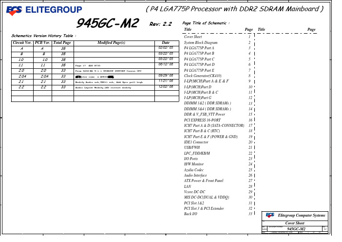
945gc-m2_v22bom主板电路图纸
C
B
9 9 9 9 9 9 9 9 9 9 9 9 9 9 9 9 9 9 9 9 9 9 9 9 9 9 9 9 9 9 9 9 9 9 9 9 9 9 9 9 9 9 9 9 9 9 9 9 9 9 9 9 9 9 9 9 9 9 9 9 9 9 9 9
H_D0 H_D1 H_D2 H_D3 H_D4 H_D5 H_D6 H_D7 H_D8 H_D9 H_D10 H_D11 H_D12 H_D13 H_D14 H_D15 H_D16 H_D17 H_D18 H_D19 H_D20 H_D21 H_D22 H_D23 H_D24 H_D25 H_D26 H_D27 H_D28 H_D29 H_D30 H_D31 H_D32 H_D33 H_D34 H_D35 H_D36 H_D37 H_D38 H_D39 H_D40 H_D41 H_D42 H_D43 H_D44 H_D45 H_D46 H_D47 H_D48 H_D49 H_D50 H_D51 H_D52 H_D53 H_D54 H_D55 H_D56 H_D57 H_D58 H_D59 H_D60 H_D61 H_D62 H_D63
H_D0 H_D1 H_D2 H_D3 H_D4 H_D5 H_D6 H_D7 H_D8 H_D9 H_D10 H_D11 H_D12 H_D13 H_D14 H_D15 H_D16 H_D17 H_D18 H_D19 H_D20 H_D21 H_D22 H_D23 H_D24 H_D25 H_D26 H_D27 H_D28 H_D29 H_D30 H_D31 H_D32 H_D33 H_D34 H_D35 H_D36 H_D37 H_D38 H_D39 H_D40 H_D41 H_D42 H_D43 H_D44 H_D45 H_D46 H_D47 H_D48 H_D49 H_D50 H_D51 H_D52 H_D53 H_D54 H_D55 H_D56 H_D57 H_D58 H_D59 H_D60 H_D61 H_D62 H_D63 H_RS0_L H_RS1_L H_RS2_L
英飞凌单片机选型

程序 [PS RAM] 数据 Mem [DS RAM]
双端口[DPRAM]
Trace Mem for MCDS SB RAM CAN Standby 通道数
2
2
4
2
2
2
2
2
8 最多6
8 最多6
8 最多6
1 最多5
8 最多6 最多2 -
ADC
通道数
24
最多10 0 1 4 最多2 QFP 100 / 144
PMI 48 kB SPRAM 16 kB ICACHE
FPU TriCore (TC-1M) CPS PBCU
Program Local Memory Bus PLMB Data Local Memory Bus DLMB
24kB
Vector Computer
16kB NEW 8kB NEW
XC836
Vector Computer
XC866
PWM unit
XC866
PWM unit
4kB
2kB
XC822
MDU
XC836
Vector Computer
XC866
PWM unit
XC822
MDU
TSSOP16 TSSOP28 TSSOP38 VQFN48
•与8051内核兼容 •于1978年推出的全球第一款 用于动力总成系统的单片机 •高性能的8位单片机,其每条指令周期为两个 机器周期
•在动力总成系统中广泛使用的内 •曾占有50% 的欧洲汽车市场及 30% 的全球市场份额 •每年2500万片的产量
04.05.2012
XC800 家族成员
NEW 64kB
24 / 30/40
贴片压敏电阻2220封装参数型号规格书大全

UN2220-XXXH SeriesModel1005(0402)1608(0603)2012(0805)3216(1206)3225(1210)4532(1812)5750(2220)8050(3220)Length(L) 1.00±0.15 1.60±0.20 2.00±0.20 3.20±0.20 3.20±0.20 4.50±0.30 5.70±0.308.0±0.30Width(W)0.50±0.150.80±0.20 1.20±0.20 1.60±0.20 2.50±0.20 3.20±0.20 5.00±0.30 5.00±0.30High(H)0.70max0.90max1.30max1.60max2.50max3.20max4.50max4.50maxFeaturePart Numbering◆Body ZnO◆End termination Ag/Ni/Sn ◆Packaging Bulk/Tape ◆Complies with StandardIEC61000-4-5◆AC voltage at 50~60Hz◆Varistor voltage :Measured at 1mA DC ◆Capacitance :Measured at f=1MHz,Vrms=0.5V◆Maximum clamping voltage :Measured at 10A by 8/20µs Pulse◆Rated peak single pulse transient current :Measured by 8/20µs PulseUN -2220270-H (1)(2)(3)(4)(1)Series Name(2)2220:Chip size –2220(5.7x 5.0mm)size(3)270:Varistor voltage(Breakdown voltage)–270Vdc (4)High surge absorption seriesDimensionsNotes @(Electrical Characteristics )◆Varistor Voltage from 12V to 360V ◆Fast response time ◆Low leakage current ◆High surge current ability◆Bidirectional clamping,high energy◆Wide Operating temperature range from -55℃-125℃◆Suitable for ESD protectionMechanical DataLW HL1UN2220-XXXH SeriesPart NumberWorking Voltage (1)Breakdown Voltage (2)Peak Current (5)Clamping Voltage (4)Typical capacitance value (3)(pF)AC DC @1mA DC8/20μS 8/20μS V RMSV DCV BI P(MAX)V CAUN2220-120H 7.09.01210-14120024104500UN2220-180H 11141815.5-21120030104500UN2220-210H 12162119-23120035104500UN2220-240H 14182422-27120038104000UN2220-270H 17222724-30120042103500UN2220-300H 19243027-33120047103000UN2220-330H 20263329-36120054102700UN2220-370H 22283732-39120046102700UN2220-390H 24303935-43120065102700UN2220-470H 28364742-52120077102500UN2220-530H 30425347-58.5120085102000UN2220-560H 35455650-62120090101500UN2220-600H 36476053-66120098101500UN2220-680H 40566860-751200110101500UN2220-760H 45607668-841200120101500UN2220-820H 50658273-911200135101500UN2220-900H 52689080-1001200150101500UN2220-101H 608510090-1101200165101500UN2220-121H 75100120108-1321200200101500UN2220-151H 95125150135-1651200250101500UN2220-181H 115150180162-1981200300101500UN2220-201H 130170205184.5-225.51200340101500UN2220-221H 140180220198-2421200360101500UN2220-241H 150200240216-2641200395101500UN2220-271H 175225270243-2971200445101500UN2220-361H230300360324-3961200595101500Symbol ParameterValue Units E Maximum Energy Absorption 10/1000µs 2.6J T J Operating ambient temperature -40~+125ºC T STG Storage Temperature Range-40~+125ºC T L Reflow temperature profile(Recommend)260ºC T rise Response time<5ns I L Leakage current at V DC (At initial state)<50µΑI LALeakage current at V DC (After reliability Test)<100µΑElectrical Characteristics (@25℃Unless Otherwise Specified )Reference DataUN2220-XXXH SeriesSurge Wave FormEnviromental Reliability Test Enviromental Reliability Test IEC61000-4-5 StandardsT1T2SEVERITY LEVELT1 T2 1 8 uS 20 uS 210 uS1000 uS8/20µs waveform currentEnviromental Reliability TestCharacteristic Test method and descriptionHigh Temperature Storage The specimen shall be subjected to 125℃ for 1000 hours in a thermostatic bath without load and then stored at room temperature and humidity for 1 to 2 hours. The change ofvaristor voltage shall be within 10%.Step Temperature Period 1 -40±3℃30min ±3 2 Room Temperature 1~2hours3 125±2℃30min ±3Temperature CycleThe temperature cycle of specified temperature shall be repeated five times and then stored at room temperature and humidity for one two hours. The change of varistor voltage shall be within 10%and mechanical damage shall be examined.4Room Temperature 1~2hoursHigh Temperature LoadAfter being continuously applied the maximum allowable voltage at 85℃ for 1000hours, the specimen shall be stored at room temperature and humidity for one or hours, the change of varistor voltage shall be within 10%.Damp Heat Load/Humidity LoadThe specimen should be subjected to 40℃,90 to 95%RH environment, and the maximum allowable voltage applied for 1000 hours, then stored at room temperature and humidity for one or two hours. The change of varistor voltage shall be within 10%.Low Temperature Storage The specimen should be subjected to -40℃, without load for 1000 hours and thenstored at room temperature for one two hours. The change of varistor voltage shall bewithin 10%.UN2220-XXXH SeriesPackaging Specification◆Carrier tape transparent cover tape should be heat-sealed to carry the products,and the reel should beused to reel the carrier tape.◆The adhesion of the heat-sealed cover tape shall be40﹢20/﹣15grams.◆Both the head and the end portion of taping shall be empty for reel package and SMT auto-pickupmachine.And a normal paper tape shall be connected in the head of taping for the operator handle.typeA0±0.10B0±0.10K0±0.10T±0.05T2±0.05D0+0.10D1±0.05P1±0.10P2±0.05P0±0.05W±0.20E±0.10F±0.050402 1.08 1.88 1.04 0.22 0.87 1.50 1.00 4.00 2.00 4.00 8.00 1.75 3.50 0603 1.08 1.88 1.04 0.22 1.17 1.50 1.00 4.00 2.00 4.00 8.00 1.75 3.50 0805 1.42 2.30 1.04 0.22 1.26 1.50 1.00 4.00 2.00 4.00 8.00 1.75 3.50 1206 1.88 3.50 1.27 0.20 1.49 1.50 1.00 4.00 2.00 4.00 8.00 1.75 3.50 1210 2.18 3.46 1.45 0.22 1.77 1.50 1.00 4.00 2.00 4.00 8.00 1.75 3.50 1812 3.66 4.95 1.74 0.25 1.99 1.50 1.50 8.00 2.00 4.00 12.00 1.75 5.50 2220 5.10 5.97 2.80 0.25 3.05 1.50 1.50 8.00 2.00 4.00 12.00 1.75 5.50 3220 5.50 8.50 2.80 0.30 3.50 1.50 1.50 8.00 2.00 4.00 16.00 1.75 7.50UN2220-XXXH SeriesReelDimensionstype A B C D E W W 10402-1210178.0±1.060.0±0.5 13.0±0.2 21.0±0.2 2.0±0.5 9.0±0.50 1.5±0.15 1812-3220178.0±1.060.0±0.5 13.5±0.1 21.0±0.2 2.0±0.5 13.6±0.2 1.5±0.15paper 100004000 4000-----quantityplastic1000type 1005 1608 2012 3216 3225 4532 5750 80501000 1000--- 3000 3000。
英飞凌 FS75R12N2T7_B15 EconoPACK 2 模块数据表

EconoPACK ™2 模块 采用第七代沟槽栅/场终止IGBT7和第七代发射极控制二极管带有温度检测NTC 特性•电气特性-V CES = 1200 V-I C nom = 75 A / I CRM = 150 A -沟槽栅IGBT7-低 V CEsat-过载操作达175°C•机械特性-高功率循环和温度循环能力-集成NTC 温度传感器-铜基板-低热阻的三氧化二铝 Al 2O 3 衬底-焊接技术-标准封装可选应用•辅助逆变器•电机传动•伺服驱动器产品认证•根据 IEC 60747、60749 和 60068 标准的相关测试,符合工业应用的要求。
描述FS75R12N2T7_B15EconoPACK ™2 模块内容描述 . . . . . . . . . . . . . . . . . . . . . . . . . . . . . . . . . . . . . . . . . . . . . . . . . . . . . . . . . . . . . . . . . . . . . . . . . . . . . . . . . . . . . . . . .1特性 . . . . . . . . . . . . . . . . . . . . . . . . . . . . . . . . . . . . . . . . . . . . . . . . . . . . . . . . . . . . . . . . . . . . . . . . . . . . . . . . . . . . . . . . .1可选应用 . . . . . . . . . . . . . . . . . . . . . . . . . . . . . . . . . . . . . . . . . . . . . . . . . . . . . . . . . . . . . . . . . . . . . . . . . . . . . . . . . . . .1产品认证 . . . . . . . . . . . . . . . . . . . . . . . . . . . . . . . . . . . . . . . . . . . . . . . . . . . . . . . . . . . . . . . . . . . . . . . . . . . . . . . . . . . .1内容 . . . . . . . . . . . . . . . . . . . . . . . . . . . . . . . . . . . . . . . . . . . . . . . . . . . . . . . . . . . . . . . . . . . . . . . . . . . . . . . . . . . . . . . . .2 1封装 . . . . . . . . . . . . . . . . . . . . . . . . . . . . . . . . . . . . . . . . . . . . . . . . . . . . . . . . . . . . . . . . . . . . . . . . . . . . . . . . . . . . . . . . .3 2IGBT, 逆变器 . . . . . . . . . . . . . . . . . . . . . . . . . . . . . . . . . . . . . . . . . . . . . . . . . . . . . . . . . . . . . . . . . . . . . . . . . . . . . . . . .3 3二极管,逆变器 . . . . . . . . . . . . . . . . . . . . . . . . . . . . . . . . . . . . . . . . . . . . . . . . . . . . . . . . . . . . . . . . . . . . . . . . . . . . . . .5 4负温度系数热敏电阻 . . . . . . . . . . . . . . . . . . . . . . . . . . . . . . . . . . . . . . . . . . . . . . . . . . . . . . . . . . . . . . . . . . . . . . . . .6 5特征参数图表 . . . . . . . . . . . . . . . . . . . . . . . . . . . . . . . . . . . . . . . . . . . . . . . . . . . . . . . . . . . . . . . . . . . . . . . . . . . . . . . .7 6电路拓扑图 . . . . . . . . . . . . . . . . . . . . . . . . . . . . . . . . . . . . . . . . . . . . . . . . . . . . . . . . . . . . . . . . . . . . . . . . . . . . . . . . .12 7封装尺寸 . . . . . . . . . . . . . . . . . . . . . . . . . . . . . . . . . . . . . . . . . . . . . . . . . . . . . . . . . . . . . . . . . . . . . . . . . . . . . . . . . . .13 8模块标签代码 . . . . . . . . . . . . . . . . . . . . . . . . . . . . . . . . . . . . . . . . . . . . . . . . . . . . . . . . . . . . . . . . . . . . . . . . . . . . . . .14修订历史 . . . . . . . . . . . . . . . . . . . . . . . . . . . . . . . . . . . . . . . . . . . . . . . . . . . . . . . . . . . . . . . . . . . . . . . . . . . . . . . . . . .15免责声明 . . . . . . . . . . . . . . . . . . . . . . . . . . . . . . . . . . . . . . . . . . . . . . . . . . . . . . . . . . . . . . . . . . . . . . . . . . . . . . . . . . .161封装表 1绝缘参数特征参数代号标注或测试条件数值单位绝缘测试电压V ISOL RMS, f = 50 Hz, t = 1 min 2.5kV 模块基板材料Cu内部绝缘基本绝缘 (class 1, IEC 61140)Al2O3爬电距离d Creep端子至散热器10.0mm 电气间隙d Clear端子至散热器7.5mm 相对电痕指数CTI>200相对温度指数 (电)RTI封装140°C 表 2特征值特征参数代号标注或测试条件数值单位最小值典型值最大值杂散电感,模块L sCE17nH 模块引线电阻,端子-芯片R CC'+EE'T C=25°C, 每个开关 3.3mΩ储存温度T stg-40125°C 模块安装的安装扭距M根据相应的应用手册进行安装M5, 螺丝36Nm 重量G180g 注:The current under continuous operation is limited to 50A rms per connector pin.2IGBT, 逆变器表 3最大标定值特征参数代号标注或测试条件数值单位集电极-发射极电压V CES T vj = 25 °C1200V 连续集电极直流电流I CDC T vj max = 175 °C T C = 100 °C75A 集电极重复峰值电流I CRM t P = 1 ms150A 栅极-发射极峰值电压V GES±20V表 4特征值特征参数代号标注或测试条件数值单位最小值典型值最大值集电极-发射极饱和电压V CE sat I C = 75 A, V GE = 15 V T vj = 25 °C 1.55 1.80VT vj = 125 °C 1.69T vj = 175 °C 1.77栅极阈值电压V GEth I C = 1.28 mA, V CE = V GE, T vj = 25 °C 5.15 5.80 6.45V 栅极电荷Q G V GE = ±15 V, V CE = 600 V 1.25µC 内部栅极电阻R Gint T vj = 25 °C2Ω输入电容C ies f = 100 kHz, T vj = 25 °C, V CE = 25 V, V GE = 0 V15.1nF 反向传输电容C res f = 100 kHz, T vj = 25 °C, V CE = 25 V, V GE = 0 V0.053nF 集电极-发射极截止电流I CES V CE = 1200 V, V GE = 0 V T vj = 25 °C0.014mA 栅极-发射极漏电流I GES V CE = 0 V, V GE = 20 V, T vj = 25 °C100nA开通延迟时间(感性负载)t don I C = 75 A, V CE = 600 V,V GE = ±15 V, R Gon = 5.6 ΩT vj = 25 °C0.164µs T vj = 125 °C0.178T vj = 175 °C0.185上升时间(感性负载)t r I C = 75 A, V CE = 600 V,V GE = ±15 V, R Gon = 5.6 ΩT vj = 25 °C0.048µs T vj = 125 °C0.053T vj = 175 °C0.057关断延迟时间(感性负载)t doff I C = 75 A, V CE = 600 V,V GE = ±15 V, R Goff = 5.6 ΩT vj = 25 °C0.300µs T vj = 125 °C0.380T vj = 175 °C0.420下降时间(感性负载)t f I C = 75 A, V CE = 600 V,V GE = ±15 V, R Goff = 5.6 ΩT vj = 25 °C0.120µs T vj = 125 °C0.200T vj = 175 °C0.270开通损耗能量 (每脉冲)E on I C = 75 A, V CE = 600 V,Lσ = 35 nH, V GE = ±15 V,R Gon = 5.6 Ω, di/dt =1200 A/µs (T vj = 175 °C)T vj = 25 °C7.96mJ T vj = 125 °C10.8T vj = 175 °C12.3关断损耗能量 (每脉冲)E off I C = 75 A, V CE = 600 V,Lσ = 35 nH, V GE = ±15 V,R Goff = 5.6 Ω, dv/dt =3200 V/µs (T vj = 175 °C)T vj = 25 °C 5.02mJ T vj = 125 °C7.68T vj = 175 °C9.46(待续)表 4(续) 特征值特征参数代号标注或测试条件数值单位最小值典型值最大值短路数据I SC V GE≤ 15 V, V CC = 800 V,V CEmax=V CES-L sCE*di/dt t P≤ 8 µs,T vj=150 °C260At P≤ 7 µs,T vj=175 °C250结-外壳热阻R thJC每个 IGBT0.475K/W 外壳-散热器热阻R thCH每个 IGBT, λgrease= 1 W/(m*K)0.141K/W 允许开关的温度范围T vj op-40175°C注:T vj op > 150°C is allowed for operation at overload conditions. For detailed specifications, please refer to AN2018-14.3二极管,逆变器表 5最大标定值特征参数代号标注或测试条件数值单位反向重复峰值电压V RRM T vj = 25 °C1200V 连续正向直流电流I F75A 正向重复峰值电流I FRM t P = 1 ms150A I2t-值I2t t P = 10 ms, V R = 0 V T vj = 125 °C1150A²sT vj = 175 °C740表 6特征值特征参数代号标注或测试条件数值单位最小值典型值最大值正向电压V F I F = 75 A, V GE = 0 V T vj = 25 °C 1.72 2.10VT vj = 125 °C 1.59T vj = 175 °C 1.52反向恢复峰值电流I RM V R = 600 V, I F = 75 A,V GE = -15 V, -di F/dt =1200 A/µs (T vj = 175 °C)T vj = 25 °C43A T vj = 125 °C56T vj = 175 °C65(待续)表 6(续) 特征值特征参数代号标注或测试条件数值单位最小值典型值最大值恢复电荷Q r V R = 600 V, I F = 75 A,V GE = -15 V, -di F/dt =1200 A/µs (T vj = 175 °C)T vj = 25 °C 4.94µC T vj = 125 °C10.2T vj = 175 °C13.7反向恢复损耗(每脉冲)E rec V R = 600 V, I F = 75 A,V GE = -15 V, -di F/dt =1200 A/µs (T vj = 175 °C)T vj = 25 °C 1.45mJ T vj = 125 °C 3.32T vj = 175 °C 4.62结-外壳热阻R thJC每个二极管0.708K/W 外壳-散热器热阻R thCH每个二极管, λgrease= 1 W/(m*K)0.153K/W 允许开关的温度范围T vj op-40175°C注:T vj op > 150°C is allowed for operation at overload conditions. For detailed specifications, please refer to AN2018-14.4负温度系数热敏电阻表 7特征值特征参数代号标注或测试条件数值单位最小值典型值最大值额定电阻值R25T NTC = 25 °C5kΩR100偏差ΔR/R T NTC = 100 °C, R100 = 493 Ω-55%耗散功率P25T NTC = 25 °C20mW B-值B25/50R2 = R25 exp[B25/50(1/T2-1/(298,15 K))]3375K B-值B25/80R2 = R25 exp[B25/80(1/T2-1/(298,15 K))]3411K B-值B25/100R2 = R25 exp[B25/100(1/T2-1/(298,15 K))]3433K 注:根据应用手册标定4 负温度系数热敏电阻6电路拓扑图图 17封装尺寸图 28 模块标签代码8模块标签代码图 3修订历史修订历史修订版本发布日期变更说明1.002021-12-16Final datasheet商标所有参照产品或服务名称和商标均为其各自所有者的财产。
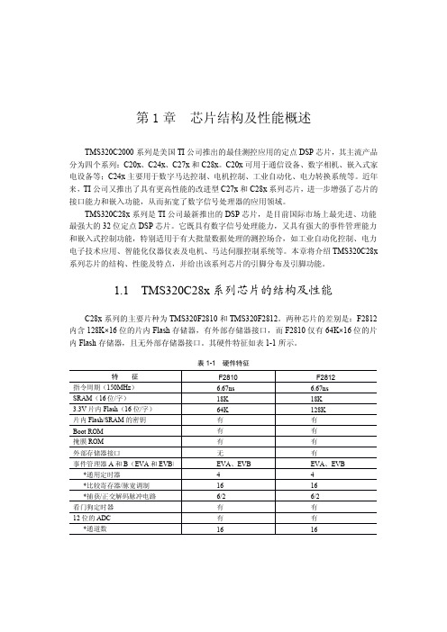
TMS320C28x系列芯片的结构及性能
—
I
PU 的操作完成且没有即将对 XINTF 进行访
问时,XINTF 释放总线。此信号是异步输
入并与 XTIMCLK 同步
XHOLDA
外部 DMA 保持确认信号。当 XINTF 响应 XHOLD 的请求时 XHOLDA 呈低电平,所
K10
82
有的 XINTF 总线 和 选 通 端 呈 高 阻 态 。
特征 指令周期(150MHz) SRAM(16 位/字) 3.3V 片内 Flash(16 位/字) 片内 Flash/SRAM 的密钥
Boot ROM 掩膜 ROM 外部存储器接口 事件管理器 A 和 B(EVA 和 EVB)
*通用定时器 *比较寄存器/脉宽调制 *捕获/正交解码脉冲电路 看门狗定时器 12 位的 ADC *通道数
·6·
TMS320C28x系列DSP的CPU与外设(上)
封装和 176 引脚 PGF 低剖面四芯线扁平 LQFP(Low-profile Quad)封装,其引脚分布分别 如图 1-2(BGA 封装底视图)和图 1-3(LQFP 封装顶视图)所示。TMS320F2810 芯片的封 装方式为 128 引脚 PBK LQFP 封装,其引脚分布情况如图 1-4(顶视图)所示。
微芯片 SmartIOC 2100 SAS I O 控制器产品介绍说明书
SummaryMicrochip SmartIOC 2100 SAS I/O Controller products provide reliable ultra-high perfor-mance HBA functionality with industry-leading low-power operation. These SmartIOCs provide unparalleled flexibility along with a broad range of standard features designed to meet the most demanding server storage applications.These SmartIOC controllers offer optional entry-level hardware RAID 0/1/10/5 modes without any external DRAM. The 24- and 16-port devices also offer additional dedicated RAID-capable boot ports.The controllers support Microchip Smart Storage Solution drivers for all major operating systems and a comprehensive set of management tools, including a GUI and CLI.12 Gbps SmartIOC 2100 SAS IO ControllersPM8222, PM8225, PM8238, PM8239, PM8242 and PM8243FeaturesHBA Features• Persistent logging and binding• Up to 1.6M IOPS performance for PM8242, PM8243, PM8238, PM8239 and up to 1.4M IOPS performance for PM8222, PM8225 (4K random reads)• Up to 6.9 GB/s bandwidth• Transport Layer Retry (TLR) support • Multi-initiator (host)/clustering for SAS • TRIM and UNMAP support for SSDs• SAS dual path failover (RAID stack managed Active/Standby)• Baseboard Management Controller (BMC) support with Management Component Transport Protocol (MCTP) over PCIe or I 2C• 4K native sector support • Hot plug drive support• Adapter power management modes • S.M.A.R.T. diagnostic access • SMP commands using ARCONF• Supports eight lanes of PCIe 3.0 to the host, each lane supporting PCIe Gen 3 rates up to 8.0 Gbps• Enclosure Management: SES-2/3 SGPIO: SFF-8485 IBPI: SFF-8489 SGPIO as a virtual SES enclosure: SFF-8448Entry-Level RAID Features• Flexible configuration for RAID mode • Dynamic sector repair • Multiple LUN support• Support for up to 238 raw devices• Support for up to 32 target devices in RAID mode• Supports up to eight SAS/SATA Logical/RAID volumes • Split mirror and combine • Copyback hot spare• Displays raw devices on connector • RAID build modes •Quick initialization• Background initialization • Rapid parity initialization • Heal array and move array • Bootable array support • Erase drive• Configurable stripe size • Bad stripe marking• Hot spare support (dedicated, global, or predictive)• Persistent logging for RAID and HBA •4K native sector support in RAIDMicrochip Storage Management Utilities maxView TM provides both server-based and remote admin-istration. This fully browser-based tool supports all standard browsers and is available through a USB boot image. maxView controller management components include:• maxView GUI• ARCCONF CLI• Event Monitor (event logging and email alerts)• VSphere plug-in• OpenStack plug-in• Smart Storage Administrator CLIHighlights• Industry-leading throughput• Compatible with Microchip Smart Storage solution drivers for all major operating systems and their unified manage-ment utilities• Two additional 6G SAS/SATA boot ports with RAID 1 sup-port included in 24 and 16 port configurations• RAID 0, 1, 10, 5 with hardware acceleration and no ad-ditional host software requirements• No DDR memory required, regardless of mode• The PM8243, PM8239, PM825 include support for maxCrypto™ controller-based encryptionTools for Setup and Troubleshooting Microchip provides a complete suite of design-in collateral to support embedded designs with this product including: refer-ence designs, detailed hardware specifications and design-in guides.• UEFI HII configuration tool• CTRL-A Legacy BIOS configuration tool• ChipLink diagnostic tools• Extensive debug, diagnostics, configuration and analy-sis tools with an intuitive GUI• Access to configuration data, management capabili-ties, and signal integrity analysis tools such as real-time eye capture• Connects to device over UART Operating System Support• Extensive operating system support includes major software releases for Windows®/Server, VMware ESXi, Red Hat Enterprise Linux®, SUSE Enterprise Linux, Ubuntu, CentOS, XenServer, Fedora, Debian, and Solaris• Certification for Microsoft WHQL, VMware IOVP and VMware VSAN High-Speed I/O• x8 PCIe Gen 3 8 GT/s• PCIe link rates supported: 8 GT/s, 5 GT/s, 2.5 GT/s• PCIe-compliant link training and manual PHYconfiguration• PM8243/PM8242: 24x SAS-3/SATA PHYs for high-speed targets• PM8239/PM8238: 16x SAS-3/SATA PHYs for high-speed targets• PM8222/PM8225: 8x SAS-3/SATA PHYs for high-speed targets• SAS or SATA operation on a per-PHY basis• SAS link rates supported: 12 Gbps, 6 Gbps, 3 Gbps• SATA link rates supported: 6 Gbps, 3 Gbps, 1.5 Gbps • PM8241/PM8242 and PM8239/PM8238: 2x SAS-2/SATA PHYs for boot devices• Independent per-channel selectable high-speed outputs support multiple programmable levels of pre-emphasis and output swing• Multiple programmable levels of receive equalization • Integrated resistive termination• Automatic negotiation of link speed• Decision Feedback Equalizer provides robust recovery of 12 Gbps SAS signals over lossy channels Peripheral I/O Interfaces• PM8241/PM8240 and PM8237/PM8236: Eight multi-master and seven master-only Two-Wire Interfaces (TWIs)• PM8205/PM8204: Seven multi-master and two master-only TWIs• TWIs support variable bit rates up to 400 Kbps• Two industry-standard 16750 UARTs• Seven SFF-8485-compliant Serial GPIO (SGPIO) ports • Up to 30 GPIO ports depending on SGPIO port configuration• Firmware API for peripheral control including features such as activity LED, UART configuration, zoning configuration, interprocessor communications and enclosure control Note: Some peripheral I/O interface pins are multiplexed. maxCrypto Encryption(PM8243, PM8239, PM825 Only)• AES data encryption and decryption with key sizes of 128/196/256The Microchip name and logo and the Microchip logo are registered trademarks, and maxCrypto and maxView are trademarks of Microchip Technology Incorporated in the U.S.A. and other countries. All other trademarks mentioned herein are property of their respective companies.© 2019, Microchip Technology Incorporated. All Rights Reserved. 8/19 DS00003021AExample ApplicationEfficient SDS for Hyperscale Data Centers• Support for high-density single-controller configurations• Up to 24 ports + 2 additional boot ports • Hardware RAID 1 on boot devices• Lower power and higher performance than multi-controller designs • No external memory required• Hardware-based value RAID 5 available• Support for vSAN and Storage Spaces DirectStorage PortsPM8243A-F3EI (with encryption)For More Informationhttps:///product-directory/smart-storage-platform/4097-12g-smartioc-2100-controllersx4SAS-3x4SAS-3。
DB_PCap01Ax_0301_电容测试芯片

RMS 噪声和精度 vs. 输出数据频率.......................................................................................................... 2-3
2.2.2
RMS 噪声 vs. 供电电压............................................................................................................................... 2-5
1.2 典型应用
湿度传感器 位移传感器 压力传感器 力学传感器 加速度传感器 倾角传感器 角度传感器 无线应用 夜位开关传感器 麦克风 MEMS 传感器
acam-messelectronic gmbh - Am Hasenbiel 27 - D-76297 Stutensee-Blankenloch - Germany - www.acam.de
3 转换器前端
3.1 CDC 测量原理 3.2 重要 CDC 参数 3.3 CDC 外部电路 3.4 连接电容传感器 3.5 选择放电电阻 3.6 补偿测量
4.1 串行通信
4 接口 (串行通信和 Pulse-Density通信) 4.2 PDM/PWM 和 GPIO
5 读 & 写寄存器 6 DSP, 存储 & 固件
1-1
4
1.3 内部结构原理图
图 1-1: 内部结构原理图
PCapØ1Ax-0301
1-2
acam-messelectronic gmbh - Am Hasenbiel 27 - D-76297 Stutensee-Blankenloch - Germany - www.acam.de
Modicon M221产品样本_中文
ଳ
ڦ
借助MachineStruxure实现机器性能和 业务绩效的最大化
ॐࠓࢅ߾ײ ీࣅ
ऄࢅકቛ
ऐഗ੦ ۨࣅࢅޜခ
机器制造商不断寻找新途径,试图在最短时间、以最低成本设计和制造更加新颖的机 器。MachineStruxureTM能够助其一臂之力。
新一代MachineStruxure是一套完整的机器自动化解决方案,提供灵活可扩展的机器 控制功能,即时可用的架构,高效的工程解决方案以及全方位定制化服务和工程支持 服务。它不仅能帮助您应对提高效率和生产力所面临的挑战,更有助于您在机器的全 生命周期为客户带来更高的附加值。
Modicon可编程控制器
Modicon M221可编程控制器
最快速最精巧的可编程控制器
灵活可扩展的机器控制
新一代MachineStruxure结合全新ModiconTM系列可编程控制器,提供前所未有的灵活 可扩展的机器控制功能。它集成以太网连接,USB端口编程,嵌入式网络服务器,功能 一应俱全。
性能在同类产 品中首屈一指
安全模块
TeSys电机起动模块 模拟量/离散量模块
> Modicon M221内置标准SD卡、运行/停止开关、USB端口、2路模拟量输入、4路高速
计数、高达2路脉冲输出、串行端口、以太网端口、扩展板等功能
> 高度的灵活性,可轻松连接扩展模块(安全模块、TeSys电机起动模块、模拟量/离散
量扩展模块等),所有模块均高度整合、一键配置
智能精巧,非同凡“想” 提升您机器的性能价值
善用其效,尽享其能 SM
5
选型指南
Modicon M221一体型及书本型 可编程控制器
应用
1
简单设备的控制应用
芯片封装图---图片+文字要点

PSDIP PLCC DIP DIP-TAB LCC LDCC LQFP LQFP FTO220HSOP28ITO220ITO3PPDIPBQFP PQFP PQFPQFP SC-70SDIP SIP SO SOD323SOJ SOJ SOT143 SOT223SOT223SOT23SOT343SOT SOT SOT523SOT89SSOP SSOP STO-220 TO18TO220TO247TO252 TO264TO3TO52TO71 TO78TO8TO92TO93PCDIP JLCC TO72STO-220TO99AX14TO263SOT89SOT23SOP SNAPTK FGIPTQFP TSOP TSSOP ZIP常见集成电路(IC)芯片的封装金属圆形封装 TO99最初的芯片封装形式。
引脚数8--12。
散热好,价格高,屏蔽性能良好,主要用于高档产品。
PZIP(Plastic Zigzag In-line Package)塑料ZIP型封装引脚数3 --16。
散热性能好,多用于大功率器件。
SIP(Single In-line Package)单列直插式封装引脚中心距通常为2.54mm,引脚数2 --23,多数为定制产品。
造价低且安装便宜,广泛用于民品。
DIP(DualIn-line Package)双列直插式封装绝大多数中小规模 IC均采用这种封装形式,其引脚数一般不超过100个。
适合在PCB板上插孔焊接,操作方便。
塑封DIP应用最广泛。
SOP(Small Out-Line Package) 双列表面安装式封装引脚有J形和L形两种形式,中心距一般分1.27mm和0.8mm两种,引脚数8--32。
体积小,是最普及的表面贴片封装。
BGA(Ball Grid Array Package)球栅阵列封装表面贴装型封装之一,其底面按阵列方式制作出球形凸点用以代替引脚。
适应频率超过100MHz ,I/O 引脚数大于208 Pin 。
APM32E103xCxE 基于 Arm Cortex-M3 内核的 32 位微控制器说明书
功能描述 .....................................................................................................................20
系统架构 ........................................................................................................................................21 4.1.1 系统框图 ..................................................................................................................................................21 4.1.2 地址映射 ..................................................................................................................................................22 4.1.3 启动配置 ..................................................................................................................................................22
英飞凌创新电源管理产品亮相PClMAsia2011
到 10亿块 以上 , 现 主 营业务 收 人 4 2 实 5亿元 , 年均
增 速在 3 %以上 。 0
日本 的灾 难性 地震 威胁 将 破坏 电子产 品供 应链 , 但 自我们 在 2 1 年第一 季度 的预测 以来 , 支 出和 01 资本
设 备格局 变化不 大 。 由于 日本 厂商艰 巨 的努力 , 此次
新 能 源功率 变换 准备 的功率 组件 等 。
月1 7日 一8日在 西安举 办 “0 1中国半 导体 行业 1 21 协会 集成 电路 设计分 会年会 暨 中国集 成 电路设计 产
业 十年成就展 ”。 本 次年 会 以 “ 化 产业 发 展 环境 , 优 提升 核 心竞
大科 技成果 、 科技 进步等 奖项 , 成 1 国家级企 业 建 个
前 的 8 0万块增 加 到 目前 的 5 0 0亿块 以上 , 身 国内 跻
同行业 内资企业 前 三位 。
同时 , 甘肃集 成 电路 产业 创新能力 亦水 涨船高 。
【 巾 r u !● i集ti — nt er j hI成Ci ■ 国e dc Cag电 t na 路
日至 2 3日)上展 示 了最 新 的 I B G T技 术 、 ol S C oMO T M
据介 绍 , 针对 产业 总量 偏 少 、 竞争 能力 较 弱 、 缺 乏 区位优势 等突 出问题 , 肃将在 “ 甘 十二五 ” 间力 期 争实现 集成 电路产业 主导产 品 由单 一 向多元 的结构
转 变 , 现技术 水平 由中低端 向高端转 变 , 实 建成 以天
水、 兰州 、 凉 为核心 的微 电子 、 平 电真空 器件 、 工 电 军
全球半 导体资本设备支 出将 达到 48亿美元 , 4 与
最新的多芯片模块(MCM)封装类型
(small die)或者小芯片(chiplet)。
这些小芯片通常采用不同的工艺节点制造,并被集成到单个封装中。
它能够满足严苛的PPA目标,是值得开发者努力的方向。
先进的芯片封装技术在创新过程中必将起到主要作用。
MulTI-die系统级封装(SiP)具有以下优势:可开发具有更多功能的产品可通过更换裸片快速开发出多个SKU可使用经过验证的裸片,减少开发风险与使用两个独立的芯片相比,mulTI-die吞吐量更高,系统功耗更低可优化系统外形尺寸,降低系统成本与使用两个独立的芯片相比,裸片间的低延迟可以提高系统性能封装行业有一系列技术可支持mulTI-die设计,例如:标准的2D封装、2.5D 先进封装,以及3D堆叠裸片,但没有哪个封装技术是可以适合所有产品的。
选择哪种封装方式将取决于产品的PPA和成本目标。
本文将简单介绍几种最新的多芯片模块(MCM)封装类型,并重点阐述die-to-die(D2D)IP如何通过这些封装来更好地支持设计流程。
四大先进芯片封装类型下一波系统设计浪潮将以先进封装中的小芯片为主导。
这些小芯片本质上也是集成电路,专门用来与其他裸片一起打造更大、更复杂的芯片,且可以被集成到先进的MCM封装中。
小芯片通常由可重复使用的IP块组成。
不同的封装类型在组装、密度和复杂性方面各不相同。
图1介绍了主要的封装类型以及它们在不同应用中的优势和劣势。
▲ 图1:主要的先进封装类型概览有机衬底有机衬底可以支持低密度的IO排布,D2D连接较少。
这种2D类型的标准封装相对便宜,在半导体行业中使用广泛。
与2.5D和3D封装不同,有机衬底封装并不存在脆弱的微凸块,并且由于工艺已十分成熟,所以往往良率更高。
它具有可测试性功能(对已知合格裸片进行低成本晶圆级筛选),但无法对故障连接进行测试和修复。
此外,有机衬底还具有良好的散热性和低翘曲性,支持大规模SiP集成,且无掩模板限制。
重分布层(RDL)扇出相对较新的RDL扇出型(Fan-Out)封装尚未得到广泛使用,其密度与硅中介层相似,但复杂性和成本却更低。
赛米控丹佛斯 配置IGBT M7芯片 SEMITRANS 3 SKM460GB12M7 数据表

Absolute Maximum Ratings Symbol Conditions Values UnitIGBT V CES T j = 25 °C 1200 V I C T j = 175 °CT c = 25 °C 581 A T c = 80 °C442 A I Cnom 460 A I CRM920 A V GES -20 (20)V t psc V CC = 800 V V GE ≤ 15 V V CES ≤ 1200 VT j = 150 °C8 μs T j-40 (175)°C Inverse diode V RRM T j = 25 °C 1200V I FT j = 175 °CT c = 25 °C 588A T c = 80 °C439 A I FRM 1000A I FSM t p = 10 ms, sin 180°, T j = 25 °C2304A T j-40 ... 175°C Module I t(RMS)500 A T stg module without TIM-40 ... 125 °C V isolAC sinus 50 Hz, t = 1 min4000VCharacteristics Symbol Conditions min. typ. max. UnitIGBT V CE(sat)I C = 460 A V GE = 15 V chiplevel T j = 25 °C 1.54 1.93V T j = 150 °C 1.81 V V CE0chiplevel T j = 25 °C 0.86 0.96 V T j = 150 °C 0.75 V r CE V GE = 15 V chiplevelT j = 25 °C 1.48 2.1 mΩ T j = 150 °C2.3 mΩ V GE(th)V CE = 10V, I C = 46 mA5.46 6.6 V I CES V GE = 0 V, V CE = 1200 V, T j = 25 °C4.6 mA C ies V CE = 10 V V GE = 0 Vf = 1 MHz88.0 nF C oes f = 1 MHz 2.76 nF C res f = 1 MHz1.08 nF Q G V GE = - 8V ... + 15 V 4100 nC R Gint T j = 25 °C 1.15 Ω t d(on)V CC = 600 V I C = 460 AV GE =+15/-15V R G on = 1 Ω R G off = 1 Ωdi/dt on = 6500 A/µs di/dt off = 4350 A/µs dv/dt = 5900 A/µs T j = 150 °C 330 ns t r T j = 150 °C 83 ns E on T j = 150 °C 60 mJ t d(off)T j = 150 °C 400 ns t f T j = 150 °C 87 ns E off T j = 150 °C49mJ R th(j-c)per IGBT0.086K/W R th(c-s)per IGBT, P12 (reference)0.032 K/W R th(c-s)per IGBT, HP-PCM0.023K/WIGBT M7 ModulesSKM460GB12M7Features*∙ V CE(sat) with positive temperature coefficient∙ High overload capability∙ Low loss high density IGBT´s ∙ Fast & soft switching inverse CAL diodes∙ Large clearance (10 mm) and creepage distances (20 mm) ∙ Insulated copper baseplate using DBC Technology (Direct Bonded Copper)∙ UL recognized, file no. E63532Typical Applications∙ AC inverter drives ∙ UPSRemarks∙ Max. case temperature limited to T C = T S = 125 °C∙Product reliability results are valid for T j = 150 °C (recommended T j,op = -40...+150 °C)∙ For storage and case temperature with TIM see document: ″Technical Explanations Thermal Interface Materials″GBSEMITRANS 3Characteristics Symbol Conditions min. typ. max. UnitInverse diode V F = V EC I F = 460 A V GE = 0 V chiplevel T j = 25 °C 2.05 2.36V T j = 150 °C 1.96 V V F0chiplevel T j = 25 °C 1.30 1.50 V T j = 150 °C 0.90 V r F chiplevelT j = 25 °C 1.64 1.88 mΩ T j = 150 °C2.3 mΩ I RRM V CC = 600 V I F = 460 AV GE = -15 Vdi/dt off = 6430 A/µs T j = 150 °C 430 A Q rr T j = 150 °C77 µC E rr T j = 150 °C 33mJ R th(j-c)per diode0.104K/W R th(c-s)per diode, P12 (reference) 0.034 K/W R th(c-s)per diode, HP-PCM0.024 K/W Module L CE 15nH R CC'+EE'measured per switchT j = 25 °C 0.55mΩ T j = 150 °C0.85 mΩ R th(c-s)1calculated without thermal coupling, P12 (reference)0.0085 K/W R th(c-s)2including thermal coupling,T s underneath module, P12 (reference)0.013 K/W R th(c-s)2including thermal coupling,T s underneath module, HP-PCM 0.0074K/W M s to heat sink M635 Nm M t to terminal M62.55 Nm -Nm w325 gSEMITRANS ® 3 IGBT M7 ModulesSKM460GB12M7Features*∙ V CE(sat) with positive temperature coefficient∙ High overload capability∙ Low loss high density IGBT´s ∙ Fast & soft switching inverse CAL diodes∙ Large clearance (10 mm) and creepage distances (20 mm) ∙ Insulated copper baseplate using DBC Technology (Direct Bonded Copper)∙ UL recognized, file no. E63532Typical Applications∙ AC inverter drives ∙ UPSRemarks∙ Max. case temperature limited to T C = T S = 125 °C∙Product reliability results are valid for T j = 150 °C (recommended T j,op = -40...+150 °C)∙ For storage and case temperature with TIM see document: ″Technical Explanations Thermal Interface Materials″GBFig. 1: Typ. output characteristic, inclusive R CC'+ EE'Fig. 2: Rated current vs. temperature I C = f (T C )Fig. 3: Typ. turn-on /-off energy = f (I C ) Fig. 4: Typ. turn-on /-off energy = f (R G )Fig. 5: Typ. transfer characteristic Fig. 6: Typ. gate charge characteristicFig. 7: Typ. switching times vs. I C Fig. 8: Typ. switching times vs. gate resistor R GFig. 9: Transient thermal impedance Fig. 10: Typ. CAL diode forward charact., incl. R CC'+ EE',Fig. 11: CAL diode peak reverse recovery current Fig. 12: Typ. CAL diode peak reverse recovery chargePinout and DimensionsGBThis is an electrostafic discharge sensifive device (ESDS) according to internafional standard IEC 61340.*IMPORTANT INFORMATION AND WARNINGSThe specificafions of SEMIKRON products may not be considered as any guarantee or assurance of product characterisfics ("Beschaffenheitsgaranfie"). The specificafions of SEMIKRON products describe only the usual characterisfics of SEMIKRON products to be expected in typical applicafions, which may sfill vary depending on the specific applicafion. Therefore, products must be tested for the respecfive applicafion in advance. Resulfing from this, applicafion adjustments of any kind may be necessary. Any user of SEMIKRON products is responsible for the safety of their applicafions embedding SEMIKRON products and must take adequate safety measures to prevent the applicafions from causing any physical injury, fire or other problem, also if any SEMIKRON product becomes faulty. Any user is responsible for making sure that the applicafion design and realizafion are compliant with all laws, regulafions, norms and standards applicable to the scope of applicafion. Unless otherwise explicitly approved by SEMIKRON in a wriften document signed by authorized representafives of SEMIKRON, SEMIKRON products may not be used in any applicafions where a failure of the product or any consequences of the use thereof can reasonably be expected to result in personal injury. No representafion or warranty is given and no liability is assumed with respect to the accuracy, completeness and/or use of any informafion herein, including without limitafion, warranfies of non-infringement of intellectual property rights of any third party. SEMIKRON does not convey any license under its or a third party’s patent rights, copyrights, trade secrets or other intellectual property rights, neither does it make any representafion or warranty of non-infringement of intellectual property rights of any third party which may arise from a user’s applicafions. Due to technical requirements our products may contain dangerous substances. For informafion on the types in quesfion please contact the nearest SEMIKRON sales office. This document supersedes。
