CISCO Guard 配置实例
CISCO交换机配置实例
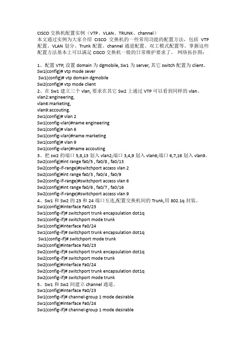
CISCO交换机配置实例(VTP、VLAN、TRUNK、channel)本文通过实例为大家介绍CISCO交换机的一些常用功能的配置方法,包括VTP 配置、VLAN划分、Trunk配置、channel通道配置、双工模式配置等。
掌握这些配置方法基本上可以满足CISCO交换机一般的日常维护要求了。
网络拓扑图:1、配置VTP, 设置domain为dgmobile, Sw1为server, 其它switch配置为client。
Sw1(config)# vtp mode severSw1(config)# vtp domain dgmobileSw2(config)# vtp mode client2、在Sw1建立三个vlan, 要求在其它Sw2上通过VTP可以看到同样的vlan。
vlan2:engineering,vlan6:marketing,vlan9:accouting.Sw1(config)# vlan 2Sw1(config-vlan)#name engineeringSw1(config)# vlan 6Sw1(config-vlan)#name marketingSw1(config)# vlan 9Sw1(config-vlan)#name accouting3、把sw2的端口5,8,13划入vlan2;端口3,4,9划入vlan6;端口6,7,16划入vlan9。
Sw2(config)#int range fa0/5 , fa0/8 , fa0/13Sw2(config-if-range)#switchport access vlan 2Sw2(config)#int range fa0/3 , fa0/4 , fa0/9Sw2(config-if-range)#switchport access vlan 6Sw2(config)#int range fa0/6 , fa0/7 , fa0/16Sw2(config-if-range)#switchport access vlan 94、Sw1和Sw2的23和24端口互连,配置交换机间的Trunk,用802.1q封装。
开启Cisco交换机IP Source Guard功能

开启Cisco交换机IP Source Guard功能-------------------------------------------------------------------------------- 日期:2009-4-3 浏览次数:8469出处:一、IP地址盗用IP地址的盗用方法多种多样,其常用方法主要有以下几种:1、静态修改IP地址对于任何一个TCP/IP实现来说,IP地址都是其用户配置的必选项。
如果用户在配置TCP/IP或修改TCP/IP配置时,使用的不是授权分配的IP地址,就形成了IP地址盗用。
由于IP地址是一个逻辑地址,因此无法限制用户对于其主机IP地址的静态修改。
2、成对修改IP-MAC地址对于静态修改IP地址的问题,现在很多单位都采用IP与MAC绑定技术加以解决。
针对绑定技术,IP盗用技术又有了新的发展,即成对修改IP-MAC地址。
现在的一些兼容网卡,其MAC地址可以使用网卡配置程序进行修改。
如果将一台计算机的IP地址和MAC 地址都改为另外一台合法主机的IP地址和MAC地址,其同样可以接入网络。
另外,对于那些MAC地址不能直接修改的网卡来说,用户还可以采用软件的办法来修改MAC地址,即通过修改底层网络软件达到欺骗上层网络软件的目的。
3、动态修改IP地址某些攻击程序在网络上收发数据包,可以绕过上层网络软件,动态修改自己的IP地址(或IP-MAC地址对),以达到IP欺骗。
二、IP Source Guard技术介绍IP源防护(IP Source Guard,简称IPSG)是一种基于IP/MAC的端口流量过滤技术,它可以防止局域网内的IP地址欺骗攻击。
IPSG能够确保第2层网络中终端设备的IP地址不会被劫持,而且还能确保非授权设备不能通过自己指定IP地址的方式来访问网络或攻击网络导致网络崩溃及瘫痪。
交换机内部有一个IP源绑定表(IP Source Binding Table)作为每个端口接受到的数据包的检测标准,只有在两种情况下,交换机会转发数据:所接收到的IP包满足IP源绑定表中Port/IP/MAC的对应关系所接收到的是DHCP数据包其余数据包将被交换机做丢弃处理。
开启Cisco交换机IPSG功能
Switch (config-if)#ip verify source port-security Switch (config-if)#ip verify source vlan dhcp-snooping port-security 不加 port-security 参数,表示 IP 源防护功能只执行“源 IP 地址过滤”模式 加上 port-security 参数以后,就表示 IP 源防护功能执行“源 IP 和源 MAC 地址过滤”模式 另外,在执行这两条命令之前需要先执行 switchport port-security 命令。
PC 没有发送 DHCP 请求时,其连接的交换机端口默认拒绝除了 DHCP 请求之外的所有数据包,因此 PC 使用静态 IP 是无法连接网络的(除非已经存在绑定好的源 IP 绑定条目,如静态源 IP 绑定条目或者是 之前已经生成的动态 IP 绑定条目还没过期,而且 PC 还必须插在正确的端口并设置正确的静态 IP 地址)。
IP 源防护功能不能防止客户端 PC 的 ARP 攻击。ARP 攻击问题必须由 DAI 功能来解决。
如果要支持 IP 源防护功能,必须是 35 系列及以上的交换机。2960 目前不支持该功能。
三、IP Source Guard 的配置
Switch(config-if)# ip verify source Switch(config-if)#ip verify source vlan dhcp-snooping //接口级命令;在该接口下开启 IP 源防护功能;
以DHCP Snooping 技术为前提讲一下 IP Source Guard 技术的原理。在这种环境下,连接在交换机上的 所有 PC 都配置为动态获取 IP 地址,PC 作为 DHCP 客户端通过广播发送 DHCP 请求,DHCP 服务器将含 有 IP 地址信息的 DHCP 回复通过单播的方式发送给 DHCP 客户端,交换机从 DHCP 报文中提取关键信息 (包括 IP 地址,MAC 地址,vlan 号,端口号,租期等),并把这些信息保存到 DHCP 监听绑定表中。 (以上这个过程是由 DHCP Snooping 完成的)
cisco交换机安全配置设定
cisco交换机安全配置设定你还在为不知道cisco交换机安全配置设定而烦恼么?接下来是小编为大家收集的cisco交换机安全配置设定教程,希望能帮到大家。
cisco交换机安全配置设定的方法一、交换机访问控制安全配置1、对交换机特权模式设置密码尽量采用加密和md5 hash方式switch(config)#enable secret 5 pass_string其中 0 Specifies an UNENCRYPTED password will follow5 Specifies an ENCRYPTED secret will follow建议不要采用enable password pass_sting密码,破解及其容易!2、设置对交换机明文密码自动进行加密隐藏switch(config)#service password-encryption3、为提高交换机管理的灵活性,建议权限分级管理并建立多用户switch(config)#enable secret level 7 5 pass_string7 /7级用户进入特权模式的密码switch(config)#enable secret 5 pass_string15 /15级用户进入特权模式的密码switch(config)#username userA privilege 7 secret 5 pass_userAswitch(config)#username userB privilege 15 secret 5 pass_userB/为7级,15级用户设置用户名和密码,Cisco privilege level分为0-15级,级别越高权限越大switch(config)#privilege exec level 7 commands /为7级用户设置可执行的命令,其中commands可以根据分配给用户的权限自行定义4、本地console口访问安全配置switch(config)#line console 0switch(config-line)#exec-timeout 5 0 /设置不执行命令操作的超时时间,单位为分钟和秒switch(config-line)#logging synchronous /强制对弹出的干扰日志信息进行回车换行,使用户输入的命令连续可见设置登录console口进行密码验证方式(1):本地认证switch(config-line)#password 7 pass_sting /设置加密密码switch(config-line)#login /启用登录验证方式(2):本地AAA认证switch(config)#aaa new-model /启用AAA认证switch(config)#aaa authentication login console-in group acsserver local enable/设置认证列表console-in优先依次为ACS Server,local用户名和密码,enable特权密码switch(config)#line console 0switch(config-line)# login authentication console-in /调用authentication设置的console-in列表5、远程vty访问控制安全配置switch(config)#access-list 18 permit host x.x.x.x /设置标准访问控制列表定义可远程访问的PC主机switch(config)#aaa authentication login vty-in group acsserver local enable/设置认证列表vty-in, 优先依次为ACS Server,local用户名和密码,enable特权密码switch(config)#aaa authorization commands 7 vty-in group acsserver local if-authenticated/为7级用户定义vty-in授权列表,优先依次为ACS Server,local 授权switch(config)#aaa authorization commands 15 vty-in group acsserver local if-authenticated/为15级用户定义vty-in授权列表,优先依次为ACS Server,local授权switch(config)#line vty 0 15switch(config-line)#access-class 18 in /在线路模式下调用前面定义的标准ACL 18switch(config-line)#exec-timeout 5 0 /设置不执行命令操作的超时时间,单位为分钟和秒switch(config-line)#authorization commands 7 vty-in /调用设置的授权列表vty-inswitch(config-line)#authorization commands 15 vty-inswitch(config-line)#logging synchronous /强制对弹出的干扰日志信息进行回车换行,使用户输入的命令连续可见switch(config-line)#login authentication vty-in /调用authentication设置的vty-in列表switch(config-line)#transport input ssh /有Telnet协议不安全,仅允许通过ssh协议进行远程登录管理6、AAA安全配置switch(config)#aaa group server tacacs+ acsserver /设置AAA 服务器组名switch(config-sg-tacacs+)#server x.x.x.x /设置AAA服务器组成员服务器ipswitch(config-sg-tacacs+)#server x.x.x.xswitch(config-sg-tacacs+)#exitswitch(config)# tacacs-server key paa_string /设置同tacacs-server服务器通信的密钥二、交换机网络服务安全配置禁用不需要的各种服务协议switch(config)#no service padswitch(config)#no service fingerswitch(config)#no service tcp-small-serversswitch(config)#no service udp-small-serversswitch(config)#no service configswitch(config)#no service ftpswitch(config)#no ip http serverswitch(config)#no ip http secure-server/关闭http,https远程web管理服务,默认cisco交换机是启用的三、交换机防攻击安全加固配置MAC Flooding(泛洪)和Spoofing(欺骗)攻击预防方法:有效配置交换机port-securitySTP攻击预防方法:有效配置root guard,bpduguard,bpdufilterVLAN,DTP攻击预防方法:设置专用的native vlan;不要的接口shut或将端口模式改为accessDHCP攻击预防方法:设置dhcp snoopingARP攻击预防方法:在启用dhcp snooping功能下配置DAI和port-security在级联上层交换机的trunk下switch(config)#int gi x/x/xswitch(config-if)#sw mode trunkswitch(config-if)#sw trunk encaps dot1qswitch(config-if)#sw trunk allowed vlan x-xswitch(config-if)#spanning-tree guard loop/启用环路保护功能,启用loop guard时自动关闭root guard 接终端用户的端口上设定switch(config)#int gi x/x/xswitch(config-if)#spanning-tree portfast/在STP中交换机端口有5个状态:disable、blocking、listening、learning、forwarding,只有处于forwarding状态的端口才可以发送数据。
交换机路由防火墙配置实例

在网络中,防火墙、交换机和路由器通常是网络安全的重要组成部分。
以下是一个简单的示例,演示如何配置一个具有防火墙功能的路由器和交换机。
请注意,实际配置可能会根据您的网络架构和设备型号而有所不同。
设备列表:路由器:使用Cisco设备作为示例,实际上可以是其他厂商的路由器。
路由器IP地址:192.168.1.1交换机:同样,使用Cisco设备作为示例。
交换机IP地址:192.168.1.2防火墙规则:允许内部网络向外部网络发出的通信。
阻止外部网络对内部网络的未经请求的通信。
配置示例:1. 配置路由器:Router(config)# interface GigabitEthernet0/0Router(config-if)# ip address 192.168.1.1 255.255.255.0Router(config-if)# no shutdownRouter(config)# interface GigabitEthernet0/1Router(config-if)# ip address [外部IP地址] [外部子网掩码]Router(config-if)# no shutdownRouter(config)# ip route 0.0.0.0 0.0.0.0 [外部网关]2. 配置防火墙规则:Router(config)# access-list 101 permit ip 192.168.1.0 0.0.0.255 anyRouter(config)# access-list 101 deny ip any 192.168.1.0 0.0.0.255Router(config)# access-list 101 permit ip any anyRouter(config)# interface GigabitEthernet0/1Router(config-if)# ip access-group 101 in3. 配置交换机:Switch(config)# interface Vlan1Switch(config-if)# ip address 192.168.1.2 255.255.255.0Switch(config-if)# no shutdown配置说明:路由器通过两个接口连接内部网络(192.168.1.0/24)和外部网络。
CISCO guard配置
转--guard配置Guard 配置Step by Step1. Guard的连接和初始配置对Guard的起始配置是需要通过串行线连接的,使用admin用户名,缺省口令为rhadmin。
Console8 ,N , 1 , Flow control: None ) Properties SettingsInsert the following values and click OK:Emulation: VT100Telnet terminal ID: VT100Backscroll buffer lines: 500login prompt: admin/rhadmin2. Guard命令行配置网络部分连接物理端口:Interfaces: Eth0(百兆带外)-常用, Eth1 (千兆带外)Giga0 与 Giga1 ( 首选带内 copper / fiber )配置管理端口,带内GE端口的相关地址。
user@GUARD # Config terminaluser@GUARD-conf#interface giga1 ( 网络端口,可配置子接口)user@GUARD-conf-if-giga1# ip address 61.55.134.243 255.255.255.248user@GUARD-conf-if-giga1# no shutdownuser@GUARD-conf-if-giga1# exituser@GUARD-conf#interface eth0 ( 管理端口 ,注意接对端口)user@GUARD-conf-if-eth0# ip address 221.192.133.111 255.255.254.0user@GUARD-conf-if-eth0# no shutdownuser@GUARD-conf-if-eth0# exit启动SSH和WBM服务,并标明允许SSH, WEB访问的源地址。
思科基于CiscoPT模拟器的防火墙配置实验案例详解
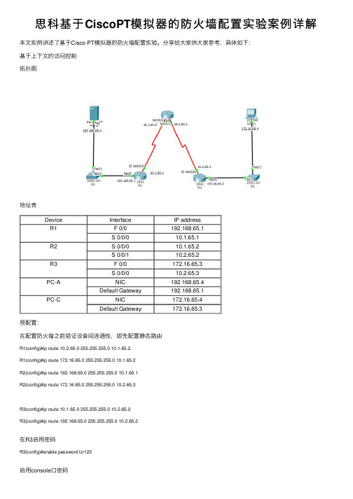
思科基于CiscoPT模拟器的防⽕墙配置实验案例详解本⽂实例讲述了基于Cisco PT模拟器的防⽕墙配置实验。
分享给⼤家供⼤家参考,具体如下:基于上下⽂的访问控制拓扑图地址表Device Interface IP addressR1 F 0/0192.168.65.1S 0/0/010.1.65.1R2S 0/0/010.1.65.2S 0/0/110.2.65.2R3 F 0/0172.16.65.3S 0/0/010.2.65.3PC-A NIC192.168.65.4Default Gateway192.168.65.1PC-C NIC172.16.65.4Default Gateway172.16.65.3预配置:在配置防⽕墙之前验证设备间连通性,即先配置静态路由R1(config)#ip route 10.2.65.0 255.255.255.0 10.1.65.2R1(config)#ip route 172.16.65.0 255.255.255.0 10.1.65.2R2(config)#ip route 192.168.65.0 255.255.255.0 10.1.65.1R2(config)#ip route 172.16.65.0 255.255.255.0 10.2.65.3R3(config)#ip route 10.1.65.0 255.255.255.0 10.2.65.2R3(config)#ip route 192.168.65.0 255.255.255.0 10.2.65.2在R3启⽤密码R3(config)#enable password lzr123启⽤console⼝密码R3(config)#line console 0R3(config-line)#password lzr123启⽤vty⾏接⼊密码R3(config)#line vty 0 4R3(config-line)#password lzr123把S1、S2所有交换机接⼝都在Vlan1(S2配置相同)S1(config)#int f 0/1S1(config-if)# switchport access vlan 1S1(config-if)# switchport trunk allowed vlan 1S1(config)#int f 0/2S1(config-if)# switchport access vlan 1S1(config-if)# switchport trunk allowed vlan 1预配置完成验证:在PC-C的命令提⽰符中ping PC-A服务器在PC-C命令提⽰符中telnet路由R2的s0/0/1接⼝:地址时10.2.65.2.退出telnet阶段在PC-C开⼀个⽹页浏览器登⼊PC-A来展⽰⽹页。
Cisco GUARD实施指南

思科自防御网络之DDOS防护实施部署指南自防御网络实践篇:之《自防御网络DDOS防护总结》更多自防御网络解决方案及中文实施指南:请登陆论坛获取1. Guard的连接和初始配置对Guard的起始配置是需要通过串行线连接的,使用admin用户名,缺省口令为rhadmin。
•Console:(8 ,N , 1 , Flow control: None ) ->Properties -> Settings•Insert the following values and click OK:–Emulation: VT100–Telnet terminal ID: VT100–Backscroll buffer lines: 500•login prompt: admin/rhadmin2. Guard命令行配置网络部分•连接物理端口:• Interfaces: Eth0(百兆带外)-常用, Eth1 (千兆带外),• Giga0 与 Giga1(首选带内 copper / fiber )•管理端口,带内GE端口的相关地址。
•user@GUARD # Config terminal•user@GUARD-conf#interface giga1•user@GUARD-conf-if-giga1# ip address 61.55.134.243 255.255.255.248•user@GUARD-conf-if-giga1# no shutdown•user@GUARD-conf-if-giga1# exit•user@GUARD-conf#interface eth0•user@GUARD-conf-if-eth0# ip address 221.192.133.111 255.255.254.0•user@GUARD-conf-if-eth0# no shutdown•user@GUARD-conf-if-eth0# exit•启动SSH和WBM服务,并标明允许SSH, WEB访问的源地址。
思科配置案例

思科配置案例在网络设备配置中,思科设备是非常常见的一种品牌,其配置方法也是网络工程师必备的技能之一。
下面我们就以一个思科路由器的配置案例来介绍一下思科设备的配置方法。
首先,我们需要登录到思科路由器的控制台界面。
一般情况下,我们可以通过串口连接或者网络连接的方式登录到路由器的控制台。
在控制台界面登录后,我们需要进入特权模式,输入enable命令并输入特权级别密码,进入特权模式后,我们就可以进行路由器的配置了。
接下来,我们需要进入全局配置模式,输入configure terminal命令,进入全局配置模式后,我们可以进行路由器的各项配置。
首先,我们可以配置路由器的主机名,输入hostname命令,后面跟上我们想要设置的主机名,比如“Router1”。
然后,我们可以配置路由器的管理IP地址,输入interface命令,后面跟上我们要配置的接口,比如“GigabitEthernet0/0”,然后输入ip address命令,后面跟上IP地址和子网掩码,比如“192.168.1.1 255.255.255.0”。
接着,我们可以配置路由器的静态路由,输入ip route命令,后面跟上目的网络和下一跳地址,比如“0.0.0.0 0.0.0.0 192.168.1.254”。
此外,我们还可以配置路由器的动态路由,比如OSPF或者EIGRP协议,来实现路由器之间的动态路由学习和交换。
最后,我们可以配置路由器的密码,比如Telnet登录密码、Enable密码等,以提高路由器的安全性。
在配置完成后,我们可以通过show命令来查看我们所配置的路由器信息,比如show ip interface brief、show running-config等命令来查看路由器的接口信息和当前的配置信息。
最后,我们可以通过write命令来保存我们的配置,使其永久生效。
以上就是一个简单的思科路由器配置案例,通过这个案例,我们可以了解到思科设备的基本配置方法,希望对大家有所帮助。
Cisco 路由器防火墙配置命令及实例

Cisco 路由器防火墙配置命令及实例一、access-list 用于创建访问规则.(1)创建标准访问列表access-list [ normal | special ] listnumber1 { permit | deny } source-addr [ source-mask ](2)创建扩展访问列表access-list [ normal | special ] listnumber2 { permit | deny } protocol source-addr source-mask [ operator port1 [ port2 ] ] dest-addr dest-mask [ operator port1 [ port2 ] | icmp-type [ icmp-code ] ] [ log ](3)删除访问列表no access-list { normal | special } { all | listnumber [ subitem ] }【参数说明】normal 指定规则加入普通时间段.special 指定规则加入特殊时间段.listnumber1 是1到99之间的一个数值,表示规则是标准访问列表规则.listnumber2 是100到199之间的一个数值,表示规则是扩展访问列表规则.permit 表明允许满足条件的报文通过.deny 表明禁止满足条件的报文通过.protocol 为协议类型,支持ICMP、TCP、UDP等,其它的协议也支持,此时没有端口比较的概念;为IP时有特殊含义,代表所有的IP协议.source-addr 为源地址.source-mask 为源地址通配位,在标准访问列表中是可选项,不输入则代表通配位为0.0.0.0.dest-addr 为目的地址.dest-mask 为目的地址通配位.operator[可选] 端口操作符,在协议类型为TCP或UDP时支持端口比较,支持的比较操作有:等于(eq)、大于(gt)、小于(lt)、不等于(neq)或介于(range);如果操作符为range,则后面需要跟两个端口.port1 在协议类型为TCP或UDP时出现,可以为关键字所设定的预设值(如telnet)或0~65535之间的一个数值.port2 在协议类型为TCP或UDP且操作类型为range时出现;可以为关键字所设定的预设值(如telnet)或0~65535之间的一个数值.icmp-type[可选] 在协议为ICMP时出现,代表ICMP报文类型;可以是关键字所设定的预设值(如echo-reply)或者是0~255之间的一个数值.icmp-code在协议为ICMP且没有选择所设定的预设值时出现;代表ICMP码,是0~255之间的一个数值.log [可选] 表示如果报文符合条件,需要做日志.listnumber 为删除的规则序号,是1~199之间的一个数值.subitem[可选] 指定删除序号为listnumber的访问列表中规则的序号.【缺省情况】系统缺省不配置任何访问规则.【命令模式】全局配置模式【使用指南】同一个序号的规则可以看作一类规则;所定义的规则不仅可以用来在接口上过滤报文,也可以被如DDR等用来判断一个报文是否是感兴趣的报文,此时,permit与deny表示是感兴趣的还是不感兴趣的.使用协议域为IP的扩展访问列表来表示所有的IP协议.同一个序号之间的规则按照一定的原则进行排列和选择,这个顺序可以通过show access-list 命令看到.【举例】允许源地址为10.1.1.0 网络、目的地址为10.1.2.0网络的WWW访问,但不允许使用FTP.Quidway(config)#access-list 100 permit tcp 10.1.1.0 0.0.0.255 10.1.2.0 0.0.0.255 eq www Quidway(config)#access-list 100 deny tcp 10.1.1.0 0.0.0.255 10.1.2.0 0.0.0.255 eq ftp【相关命令】ip access-group二、clear access-list counters 清除访问列表规则的统计信息.clear access-list counters [ listnumber ]【参数说明】listnumber [可选] 要清除统计信息的规则的序号,如不指定,则清除所有的规则的统计信息.【缺省情况】任何时候都不清除统计信息.【命令模式】特权用户模式【使用指南】使用此命令来清除当前所用规则的统计信息,不指定规则编号则清除所有规则的统计信息.【举例】例1:清除当前所使用的序号为100的规则的统计信息.Quidway#clear access-list counters 100例2:清除当前所使用的所有规则的统计信息.Quidway#clear access-list counters【相关命令】access-list三、firewall 启用或禁止防火墙.firewall { enable | disable }【参数说明】enable 表示启用防火墙.disable 表示禁止防火墙.【缺省情况】系统缺省为禁止防火墙.【命令模式】全局配置模式【使用指南】使用此命令来启用或禁止防火墙,可以通过show firewall命令看到相应结果.如果采用了时间段包过滤,则在防火墙被关闭时也将被关闭;该命令控制防火墙的总开关.在使用firewalldisable 命令关闭防火墙时,防火墙本身的统计信息也将被清除.【举例】启用防火墙.Quidway(config)#firewall enable【相关命令】access-list,ip access-group四、firewall default 配置防火墙在没有相应的访问规则匹配时,缺省的过滤方式.firewall default { permit | deny }【参数说明】permit 表示缺省过滤属性设置为“允许”.deny 表示缺省过滤属性设置为“禁止”.【缺省情况】在防火墙开启的情况下,报文被缺省允许通过.【命令模式】全局配置模式【使用指南】当在接口应用的规则没有一个能够判断一个报文是否应该被允许还是禁止时,缺省的过滤属性将起作用;如果缺省过滤属性是“允许”,则报文可以通过,否则报文被丢弃.【举例】设置缺省过滤属性为“允许”.Quidway(config)#firewall default permit五、ip access-group 使用此命令将规则应用到接口上.使用此命令的no形式来删除相应的设置.ip access-group listnumber { in | out }[ no ] ip access-group listnumber { in | out }【参数说明】listnumber 为规则序号,是1~199之间的一个数值.in 表示规则用于过滤从接口收上来的报文.out 表示规则用于过滤从接口转发的报文.【缺省情况】没有规则应用于接口.【命令模式】接口配置模式.【使用指南】使用此命令来将规则应用到接口上;如果要过滤从接口收上来的报文,则使用in 关键字;如果要过滤从接口转发的报文,使用out 关键字.一个接口的一个方向上最多可以应用20类不同的规则;这些规则之间按照规则序号的大小进行排列,序号大的排在前面,也就是优先级高.对报文进行过滤时,将采用发现符合的规则即得出过滤结果的方法来加快过滤速度.所以,建议在配置规则时,尽量将对同一个网络配置的规则放在同一个序号的访问列表中;在同一个序号的访问列表中,规则之间的排列和选择顺序可以用show access-list命令来查看.【举例】将规则101应用于过滤从以太网口收上来的报文.Quidway(config-if-Ethernet0)#ip access-group 101 in【相关命令】access-list六、settr 设定或取消特殊时间段.settr begin-time end-timeno settr【参数说明】begin-time 为一个时间段的开始时间.end-time 为一个时间段的结束时间,应该大于开始时间.【缺省情况】系统缺省没有设置时间段,即认为全部为普通时间段.【命令模式】全局配置模式【使用指南】使用此命令来设置时间段;可以最多同时设置6个时间段,通过show timerange 命令可以看到所设置的时间.如果在已经使用了一个时间段的情况下改变时间段,则此修改将在一分钟左右生效(系统查询时间段的时间间隔).设置的时间应该是24小时制.如果要设置类似晚上9点到早上8点的时间段,可以设置成“settr 21:00 23:59 0:00 8:00”,因为所设置的时间段的两个端点属于时间段之内,故不会产生时间段内外的切换.另外这个设置也经过了2000问题的测试.【举例】例1:设置时间段为8:30 ~ 12:00,14:00 ~ 17:00.Quidway(config)#settr 8:30 12:00 14:00 17:00例2:设置时间段为晚上9点到早上8点.Quidway(config)#settr 21:00 23:59 0:00 8:0【相关命令】timerange,show timerange七、show access-list 显示包过滤规则及在接口上的应用.show access-list [ all | listnumber | interface interface-name ]【参数说明】all 表示所有的规则,包括普通时间段内及特殊时间段内的规则.listnumber 为显示当前所使用的规则中序号为listnumber的规则.interface 表示要显示在指定接口上应用的规则序号.interface-name 为接口的名称.【命令模式】特权用户模式【使用指南】使用此命令来显示所指定的规则,同时查看规则过滤报文的情况.每个规则都有一个相应的计数器,如果用此规则过滤了一个报文,则计数器加1;通过对计数器的观察可以看出所配置的规则中,哪些规则是比较有效,而哪些基本无效.可以通过带interface关键字的show access-list命令来查看某个接口应用规则的情况.【举例】例1:显示当前所使用的序号为100的规则.Quidway#show access-list 100Using normal packet-filtering access rules now.100 deny icmp 10.1.0.0 0.0.255.255 any host-redirect (3 matches,252 bytes -- rule 1)100 permit icmp 10.1.0.0 0.0.255.255 any echo (no matches -- rule 2)100 deny udp any any eq rip (no matches -- rule 3)例2:显示接口Serial0上应用规则的情况.Quidway#show access-list interface serial 0Serial0:access-list filtering In-bound packets : 120access-list filtering Out-bound packets: None【相关命令】access-list八、show firewall 显示防火墙状态.show firewall【命令模式】特权用户模式【使用指南】使用此命令来显示防火墙的状态,包括防火墙是否被启用,启用防火墙时是否采用了时间段包过滤及防火墙的一些统计信息.【举例】显示防火墙状态.Quidway#show firewallFirewall is enable, default filtering method is 'permit'.TimeRange packet-filtering enable.InBound packets: None;OutBound packets: 0 packets, 0 bytes, 0% permitted,0 packets, 0 bytes, 0% denied,2 packets, 104 bytes, 100% permitted defaultly,0 packets, 0 bytes, 100% denied defaultly.From 00:13:02 to 06:13:21: 0 packets, 0 bytes, permitted.【相关命令】firewall九、show isintr 显示当前时间是否在时间段之内.show isintr【命令模式】特权用户模式【使用指南】使用此命令来显示当前时间是否在时间段之内.【举例】显示当前时间是否在时间段之内.Quidway#show isintrIt is NOT in time ranges now.【相关命令】timerange,settr十、show timerange 显示时间段包过滤的信息.show timerange【命令模式】特权用户模式【使用指南】使用此命令来显示当前是否允许时间段包过滤及所设置的时间段.【举例】显示时间段包过滤的信息.Quidway#show timerangeTimeRange packet-filtering enable.beginning of time range:01:00 - 02:0003:00 - 04:00end of time range.【相关命令】timerange,settr十一、timerange 启用或禁止时间段包过滤功能.timerange { enable | disable }【参数说明】enable 表示启用时间段包过滤.disable 表示禁止采用时间段包过滤.【缺省情况】系统缺省为禁止时间段包过滤功能.【命令模式】全局配置模式【使用指南】使用此命令来启用或禁止时间段包过滤功能,可以通过show firewall命令看到,也可以通过show timerange命令看到配置结果.在时间段包过滤功能被启用后,系统将根据当前的时间和设置的时间段来确定使用时间段内(特殊)的规则还是时间段外(普通)的规则.系统查询时间段的精确度为1分钟.所设置的时间段的两个端点属于时间段之内.【举例】启用时间段包过滤功能.Quidway(config)#timerange enable【相关命令】settr,show timerangeCisco PIX防火墙配置(转载)硬件防火墙,是网络间的墙,防止非法侵入,过滤信息等,从结构上讲,简单地说是一种PC式的电脑主机加上闪存(Flash)和防火墙操作系统。
Cisco路由器配置实例(经典)
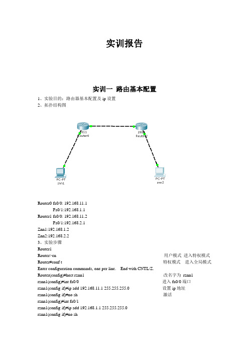
实训报告实训一路由基本配置1、实验目的:路由器基本配置及ip设置2、拓扑结构图Router0 fa0/0: 192.168.11.1Fa0/1:192.168.1.1Router1 fa0/0: 192.168.11.2Fa0/1:192.168.2.1Znn1:192.168.1.2Znn2:192.168.2.23、实验步骤Router1Router>en 用户模式进入特权模式Router#conf t 特权模式进入全局模式Enter configuration commands, one per line. End with CNTL/Z.Router(config)#host rznn1 改名字为rznn1rznn1(config)#int fa0/0 进入fa0/0端口rznn1(config-if)#ip add 192.168.11.1 255.255.255.0 设置ip地址rznn1(config-if)#no sh 激活rznn1(config)#int fa0/1rznn1(config-if)#ip add 192.168.1.1 255.255.255.0rznn1(config-if)#no shrznn1(config-if)#exitrznn1(config)#exitrznn1#copy running-config startup-config 保存Destination filename [startup-config]? startup-configrznn1#conf trznn1(config)#enable secret password 222 设置密文rznn1#show ip interface b 显示Interface IP-Address OK? Method Status Protocol FastEthernet0/0 192.168.11.1 YES manual up up FastEthernet0/1 192.168.1.1 YES manual up upVlan1 unassigned YES manual administratively down downrouter 2outer>enRouter#conf tEnter configuration commands, one per line. End with CNTL/Z.Router(config)#host rznn2rznn2(config)#int fa0/0rznn2(config-if)#ip add 192.168.11.2 255.255.255.0rznn2(config-if)#no shrznn2(config)#int fa0/1rznn2(config-if)#ip add 192.168.2.1 255.255.255.0rznn2(config-if)#no shRznn2#copy running-config startup-config 保存Destination filename [startup-config]? startup-configrznn2(config-if)#exitrznn2(config)#exitrznn2#conf trznn2(config)#enable secret 222rznn2#show ip interface bInterface IP-Address OK? Method Status Protocol FastEthernet0/0 192.168.11.2 YES manual up up FastEthernet0/1 192.168.2.1 YES manual up upVlan1 unassigned YES manual administratively down down实训二1、远程登录、密码设置及验证为路由器开设telnet端口,PC机可以远程登陆到Rznn3(Router 1)拓扑结构图Router0:192.168.1.1Pc:192.168.1.2步骤rznn3>rznn3>enrznn3#conf tEnter configuration commands, one per line. End with CNTL/Z.rznn3(config)#no ip domain lookuprznn3(config)#line cons 0rznn3(config-line)#password znnrznn3(config-line)#loginrznn3(config-line)#no exec-trznn3(config-line)#logg syncrznn3(config-line)#exitrznn3(config)#int fa0/0rznn3(config-if)#ip add 192.168.1.1 255.255.255.0rznn3(config-if)#no shrznn3(config-if)#exitrznn3(config)#line vty 0 4 打通五个端口rznn3(config-line)#password cisco 设置密码rznn3(config-line)#login 保存rznn3(config-line)#exit4、测试:实训三命令组1、目的:八条命令(no ip domain lookup\line cons 0\password\login\no exec-t\logg sync\show version\reload\copy running-config startup-config)\show cdp neighbors)2、拓扑结构图Router0 fa0/0: 192.168.11.1Router1 fa0/0: 192.168.11.23、步骤rznn1#conf tEnter configuration commands, one per line. End with CNTL/Z.1、rznn1(config)#no ip domain lookup 取消域名查找转换2、rznn1(config)#line cons 0 打开cons 0端口3、rznn1(config-line)#password znn 设置密码为znnrznn1(config-line)#login 保存rznn1(config-line)#no exec-t 设置永不超时4、rznn1(config-line)#logg sync 产生日志5、rznn1#show version 显示思科路由系统版本信息Cisco IOS Software, 2800 Software (C2800NM-ADVIPSERVICESK9-M), Version 12.4(15)T1, RELEASE SOFTWARE (fc2)Technical Support: /techsupportCopyright (c) 1986-2007 by Cisco Systems, Inc.Compiled Wed 18-Jul-07 06:21 by pt_rel_team6、rznn1#show cdp neighbors 查看路由器连接的相邻路由器的相关信息Capability Codes: R - Router, T - Trans Bridge, B - Source Route BridgeS - Switch, H - Host, I - IGMP, r - Repeater, P - PhoneDevice ID Local Intrfce Holdtme Capability Platform Port IDrznn2 Fas 0/0 139 R C2800 Fas 0/07、rznn1#copy running-config startup-config 保存刚才指令Destination filename [startup-config]? startup-configBuilding configuration...[OK]8、rznn1#reload 重启路由器Proceed with reload? [confirm]System Bootstrap, Version 12.1(3r)T2, RELEASE SOFTWARE (fc1)Copyright (c) 2000 by cisco Systems, Inc.cisco 2811 (MPC860) processor (revision 0x200) with 60416K/5120K bytes of memorySelf decompressing the image :########################################################################## [OK] Restricted Rights Legendrznn1#show ip interface bInterface IP-Address OK? Method Status Protocol FastEthernet0/0 192.168.11.1 YES manual up up FastEthernet0/1 192.168.1.1 YES manual up upVlan1 unassigned YES manual administratively down down9、rznn1(config-if)#ip add 192.168.3.1 255.255.255.0 重置ip地址rznn1#show ip interface bInterface IP-Address OK? Method Status Protocol FastEthernet0/0 192.168.3.1 YES manual up up FastEthernet0/1 192.168.1.1 YES manual up up Vlan1 unassigned YES manual administratively down down实训四发现协议1、实训目的通过发现协议显示路由器相邻路由的端口信息2、拓扑结构Router0:192.168.11.1Router1:fa0/0 192.168.11.2Fa0/1 192.168.12.1Router2:192.168.12.23、步骤R1路由器Router>enRouter#conf tEnter configuration commands, one per line. End with CNTL/Z.Router(config)#host r1r1(config)#int fa0/0r1(config-if)#ip add 192.168.11.1 255.255.255.0r1(config-if)#no sh%LINK-5-CHANGED: Interface FastEthernet0/0, changed state to upr1(config-if)#r1(config-if)#exitr1(config)#exitr1#%SYS-5-CONFIG_I: Configured from console by consoler1#show ip interface bInterface IP-Address OK? Method Status Protocol FastEthernet0/0 192.168.11.1 YES manual up down FastEthernet0/1 unassigned YES manual administratively down downVlan1 unassigned YES manual administratively down downR2 路由器Router>enRouter#conf tEnter configuration commands, one per line. End with CNTL/Z.Router(config)#host r2r2(config)#int fa0/0r2(config-if)#ip add 192.168.11.2 255.255.255.0r2(config-if)#no sh%LINK-5-CHANGED: Interface FastEthernet0/0, changed state to up%LINEPROTO-5-UPDOWN: Line protocol on Interface FastEthernet0/0, changed state to up r2(config-if)#exitr2(config)#exitr2#%SYS-5-CONFIG_I: Configured from console by consoler2#conf tEnter configuration commands, one per line. End with CNTL/Z.r2(config)#int fa0/0r2(config-if)#int fa0/1r2(config-if)#ip add 192.168.12.1 255.255.255.0r2(config-if)#no sh%LINK-5-CHANGED: Interface FastEthernet0/1, changed state to upr2(config-if)#exitr2(config)#exitr2#%SYS-5-CONFIG_I: Configured from console by consoler2#show ip interface bInterface IP-Address OK? Method Status Protocol FastEthernet0/0 192.168.11.2 YES manual up upFastEthernet0/1 192.168.12.1 YES manual up down Vlan1 unassigned YES manual administratively down downR3路由器Router>enRouter#conf tEnter configuration commands, one per line. End with CNTL/Z.Router(config)#host r3r3(config)#int fa0/0r3(config-if)#ip add 192.168.12.2 255.255.255.0r3(config-if)#no sh%LINK-5-CHANGED: Interface FastEthernet0/0, changed state to up%LINEPROTO-5-UPDOWN: Line protocol on Interface FastEthernet0/0, changed state to up r3(config-if)#exitr3(config)#exitr3#%SYS-5-CONFIG_I: Configured from console by consoler3#show ip interface bInterface IP-Address OK? Method Status Protocol FastEthernet0/0 192.168.12.2 YES manual up up FastEthernet0/1 unassigned YES manual administratively down downVlan1 unassigned YES manual administratively down downR1发现邻居r1#show cdp neighborsCapability Codes: R - Router, T - Trans Bridge, B - Source Route BridgeS - Switch, H - Host, I - IGMP, r - Repeater, P - PhoneDevice ID Local Intrfce Holdtme Capability Platform Port IDr2 Fas 0/0 165 R C2800 Fas 0/0R2发现邻居r2#show cdp neighborsCapability Codes: R - Router, T - Trans Bridge, B - Source Route BridgeS - Switch, H - Host, I - IGMP, r - Repeater, P - PhoneDevice ID Local Intrfce Holdtme Capability Platform Port IDr1 Fas 0/0 176 R C1841 Fas 0/0r3 Fas 0/1 130 R C1841 Fas 0/0R3发现邻居r3#show cdp neighborsCapability Codes: R - Router, T - Trans Bridge, B - Source Route BridgeS - Switch, H - Host, I - IGMP, r - Repeater, P - PhoneDevice ID Local Intrfce Holdtme Capability Platform Port IDr2 Fas 0/0 166 R C2800 Fas 0/14、总结show 命令(1)show ip interface b (显示端口ip信息)(2)show version (显示ios版本信息)(3)show running-config (显示刚才使用的命令配置信息)(4)show cdp neighbors (显示发现邻居直连设备信息)(5)show interface (显示所有端口详细信息)实训五静态路由1、实验目的:将不同网段的网络配通(ip route)Ip route语法:ip route 目标地址子网掩码相邻路由器接口地址Show ip route2、试验拓扑:Router0:192.168.11.1Router1:fa0/0 192.168.11.2Fa0/1 192.168.12.1Router2:192.168.12.23、实验步骤:Router1Router>enRouter#conf tRouter(config)#host r1r1(config)#int fa0/0r1(config-if)#ip add 192.168.11.1 255.255.255.0r1(config-if)#no sh%LINK-5-CHANGED: Interface FastEthernet0/0, changed state to upr1(config-if)#exitr1(config)#exitr1#show ip interface bInterface IP-Address OK? Method Status ProtocolFastEthernet0/0 192.168.11.1 YES manual up downFastEthernet0/1 unassigned YES manual administratively down downVlan1 unassigned YES manual administratively down downr1#%LINEPROTO-5-UPDOWN: Line protocol on Interface FastEthernet0/0, changed state to up r1#ping 192.168.12.1Type escape sequence to abort.Sending 5, 100-byte ICMP Echos to 192.168.12.1, timeout is 2 seconds:.....Success rate is 0 percent (0/5)r1#conf tEnter configuration commands, one per line. End with CNTL/Z.r1(config)#ip route 192.168.12.0 255.255.255.0 192.168.11.2r1(config)#exitr1#ping 192.168.12.1Type escape sequence to abort.Sending 5, 100-byte ICMP Echos to 192.168.12.1, timeout is 2 seconds:Success rate is 100 percent (5/5), round-trip min/avg/max = 31/31/32 msr1#ping 192.168.12.2Type escape sequence to abort.Sending 5, 100-byte ICMP Echos to 192.168.12.2, timeout is 2 seconds:.....Success rate is 0 percent (0/5)r1#ping 192.168.12.2Type escape sequence to abort.Sending 5, 100-byte ICMP Echos to 192.168.12.2, timeout is 2 seconds:Success rate is 100 percent (5/5), round-trip min/avg/max = 47/62/78 msr1#show ip routeCodes: C - connected, S - static, I - IGRP, R - RIP, M - mobile, B - BGPD - EIGRP, EX - EIGRP external, O - OSPF, IA - OSPF inter areaN1 - OSPF NSSA external type 1, N2 - OSPF NSSA external type 2E1 - OSPF external type 1, E2 - OSPF external type 2, E - EGPi - IS-IS, L1 - IS-IS level-1, L2 - IS-IS level-2, ia - IS-IS inter area* - candidate default, U - per-user static route, o - ODRP - periodic downloaded static routeGateway of last resort is not setC 192.168.11.0/24 is directly connected, FastEthernet0/0S 192.168.12.0/24 [1/0] via 192.168.11.2Router3Router>enRouter#conf tEnter configuration commands, one per line. End with CNTL/Z.Router(config)#host r3r3(config)#int fa0/0r3(config-if)#ip add 192.168.12.2 255.255.255.0r3(config-if)#no sh%LINK-5-CHANGED: Interface FastEthernet0/0, changed state to up%LINEPROTO-5-UPDOWN: Line protocol on Interface FastEthernet0/0, changed state to up r3(config-if)#exitr3(config)#exitr3#%SYS-5-CONFIG_I: Configured from console by consoler3#show ip interface bInterface IP-Address OK? Method Status Protocol FastEthernet0/0 192.168.12.2 YES manual up up FastEthernet0/1 unassigned YES manual administratively down downVlan1 unassigned YES manual administratively down downr3#conf tEnter configuration commands, one per line. End with CNTL/Z.r3(config)#ip route 192.168.11.0 255.255.255.0 192.168.12.1r3(config)#exitr3#ping 192.168.11.2Type escape sequence to abort.Sending 5, 100-byte ICMP Echos to 192.168.11.2, timeout is 2 seconds:Success rate is 100 percent (5/5), round-trip min/avg/max = 31/31/32 msr3#ping 192.168.11.1Type escape sequence to abort.Sending 5, 100-byte ICMP Echos to 192.168.11.1, timeout is 2 seconds:Success rate is 100 percent (5/5), round-trip min/avg/max = 62/62/63 msr3#show ip routeCodes: C - connected, S - static, I - IGRP, R - RIP, M - mobile, B - BGPD - EIGRP, EX - EIGRP external, O - OSPF, IA - OSPF inter areaN1 - OSPF NSSA external type 1, N2 - OSPF NSSA external type 2i - IS-IS, L1 - IS-IS level-1, L2 - IS-IS level-2, ia - IS-IS inter area* - candidate default, U - per-user static route, o - ODRP - periodic downloaded static routeGateway of last resort is not setS 192.168.11.0/24 [1/0] via 192.168.12.1C 192.168.12.0/24 is directly connected, FastEthernet0/04、默认路由Route 1r1>enr1#conf tEnter configuration commands, one per line. End with CNTL/Z.r1(config)#no ip route 192.168.12.0 255.255.255.0 192.168.11.2%No matching route to deleter1(config)#exitr1#%SYS-5-CONFIG_I: Configured from console by consoler1#show ip routeCodes: C - connected, S - static, I - IGRP, R - RIP, M - mobile, B - BGPD - EIGRP, EX - EIGRP external, O - OSPF, IA - OSPF inter areaN1 - OSPF NSSA external type 1, N2 - OSPF NSSA external type 2E1 - OSPF external type 1, E2 - OSPF external type 2, E - EGPi - IS-IS, L1 - IS-IS level-1, L2 - IS-IS level-2, ia - IS-IS inter area* - candidate default, U - per-user static route, o - ODRP - periodic downloaded static routeGateway of last resort is not setC 192.168.11.0/24 is directly connected, FastEthernet0/0r1#conf tEnter configuration commands, one per line. End with CNTL/Z.r1(config)#ip route 0.0.0.0 0.0.0.0 192.168.11.2r1(config)#exitr1#%SYS-5-CONFIG_I: Configured from console by consoler1#show ip routeCodes: C - connected, S - static, I - IGRP, R - RIP, M - mobile, B - BGPD - EIGRP, EX - EIGRP external, O - OSPF, IA - OSPF inter areaN1 - OSPF NSSA external type 1, N2 - OSPF NSSA external type 2i - IS-IS, L1 - IS-IS level-1, L2 - IS-IS level-2, ia - IS-IS inter area* - candidate default, U - per-user static route, o - ODRP - periodic downloaded static routeGateway of last resort is 192.168.11.2 to network 0.0.0.0C 192.168.11.0/24 is directly connected, FastEthernet0/0S* 0.0.0.0/0 [1/0] via 192.168.11.2r1#ping 192.168.12.1Type escape sequence to abort.Sending 5, 100-byte ICMP Echos to 192.168.12.1, timeout is 2 seconds:Success rate is 100 percent (5/5), round-trip min/avg/max = 16/28/31 msr1#ping 192.168.12.2Type escape sequence to abort.Sending 5, 100-byte ICMP Echos to 192.168.12.2, timeout is 2 seconds: Success rate is 100 percent (5/5), round-trip min/avg/max = 62/62/63 msRoute 3r1>enr1#conf tEnter configuration commands, one per line. End with CNTL/Z.r1(config)#no ip route 192.168.12.0 255.255.255.0 192.168.11.2%No matching route to deleter1(config)#exitr1#%SYS-5-CONFIG_I: Configured from console by consoler1#show ip routeCodes: C - connected, S - static, I - IGRP, R - RIP, M - mobile, B - BGPD - EIGRP, EX - EIGRP external, O - OSPF, IA - OSPF inter areaN1 - OSPF NSSA external type 1, N2 - OSPF NSSA external type 2E1 - OSPF external type 1, E2 - OSPF external type 2, E - EGPi - IS-IS, L1 - IS-IS level-1, L2 - IS-IS level-2, ia - IS-IS inter area* - candidate default, U - per-user static route, o - ODRP - periodic downloaded static routeGateway of last resort is not setC 192.168.11.0/24 is directly connected, FastEthernet0/0r1#conf tEnter configuration commands, one per line. End with CNTL/Z.r1(config)#ip route 0.0.0.0 0.0.0.0 192.168.11.2r1(config)#exitr1#%SYS-5-CONFIG_I: Configured from console by consoler1#show ip routeCodes: C - connected, S - static, I - IGRP, R - RIP, M - mobile, B - BGPD - EIGRP, EX - EIGRP external, O - OSPF, IA - OSPF inter areaN1 - OSPF NSSA external type 1, N2 - OSPF NSSA external type 2E1 - OSPF external type 1, E2 - OSPF external type 2, E - EGPi - IS-IS, L1 - IS-IS level-1, L2 - IS-IS level-2, ia - IS-IS inter area* - candidate default, U - per-user static route, o - ODRP - periodic downloaded static routeGateway of last resort is 192.168.11.2 to network 0.0.0.0C 192.168.11.0/24 is directly connected, FastEthernet0/0S* 0.0.0.0/0 [1/0] via 192.168.11.2r3#ping 192.168.11.1Type escape sequence to abort.Sending 5, 100-byte ICMP Echos to 192.168.11.1, timeout is 2 seconds: Success rate is 100 percent (5/5), round-trip min/avg/max = 62/62/63 ms实训六动态路由RIP 协议1、实验目的使用配置动态路由启动Rip协议使用到的命令(router rip/network/show ip protocols/show ip route)2、实验拓扑R1 fa0/0 192.168.11.1R2 fa0/0 192.168.11.2fa0/1 192.168.12.1R3 fa0/0 192.168.12.23、实验步骤R1Router>enRouter#conf tEnter configuration commands, one per line. End with CNTL/Z. Router(config)#host r1r1(config)#int fa0/0r1(config-if)#ip add 192.168.11.1 255.255.255.0r1(config-if)#no shr1(config-if)#exitr1(config)#router ripr1(config-router)#network 192.168.11.0r1(config-router)#exitr1(config)#exitr1#%SYS-5-CONFIG_I: Configured from console by consoleR2Router>enRouter#conf tEnter configuration commands, one per line. End with CNTL/Z. Router(config)#host r2r2(config)#int fa0/0r2(config-if)#ip add 192.168.11.2 255.255.255.0r2(config-if)#no shr2(config-if)#exitr2(config)#int fa0/1r2(config-if)#ip add 192.168.12.1 255.255.255.0r2(config-if)#no shr2(config-if)#exitr2(config)#router ripr2(config-router)#network 192.168.11.0r2(config-router)#network 192.168.12.0r2(config-router)#exitr2(config)#exitr2#R3Router>enRouter#conf tEnter configuration commands, one per line. End with CNTL/Z. Router(config)#host r3r3(config)#int fa0/0r3(config-if)#ip add 192.168.12.2 255.255.255.0r3(config-if)#no shr3(config-if)#exitr3(config)#router ripr3(config-router)#network 192.168.12.0r3(config-router)#exitr3(config)#exitr3#%SYS-5-CONFIG_I: Configured from console by console4、实验测试R1r1#show ip protocolsRouting Protocol is "rip"Sending updates every 30 seconds, next due in 10 secondsInvalid after 180 seconds, hold down 180, flushed after 240 Outgoing update filter list for all interfaces is not setIncoming update filter list for all interfaces is not set Redistributing: ripDefault version control: send version 1, receive any version Interface Send Recv Triggered RIP Key-chain FastEthernet0/0 1 2 1Automatic network summarization is in effectMaximum path: 4Routing for Networks:192.168.11.0Passive Interface(s):Routing Information Sources:Gateway Distance Last UpdateDistance: (default is 120)r1#show ip routeCodes: C - connected, S - static, I - IGRP, R - RIP, M - mobile, B - BGPD - EIGRP, EX - EIGRP external, O - OSPF, IA - OSPF inter areaN1 - OSPF NSSA external type 1, N2 - OSPF NSSA external type 2E1 - OSPF external type 1, E2 - OSPF external type 2, E - EGPi - IS-IS, L1 - IS-IS level-1, L2 - IS-IS level-2, ia - IS-IS inter area* - candidate default, U - per-user static route, o - ODRP - periodic downloaded static routeGateway of last resort is not setC 192.168.11.0/24 is directly connected, FastEthernet0/0R 192.168.12.0/24 [120/1] via 192.168.11.2, 00:00:24, FastEthernet0/0 r1#ping 192.168.12.0Type escape sequence to abort.Sending 5, 100-byte ICMP Echos to 192.168.12.0, timeout is 2 seconds: Success rate is 100 percent (5/5), round-trip min/avg/max = 31/31/32 msR2r2#show ip protocolsRouting Protocol is "rip"Sending updates every 30 seconds, next due in 21 secondsInvalid after 180 seconds, hold down 180, flushed after 240Outgoing update filter list for all interfaces is not setIncoming update filter list for all interfaces is not setRedistributing: ripDefault version control: send version 1, receive any versionInterface Send Recv Triggered RIP Key-chain FastEthernet0/0 1 2 1FastEthernet0/1 1 2 1Automatic network summarization is in effectMaximum path: 4Routing for Networks:192.168.11.0192.168.12.0Passive Interface(s):Routing Information Sources:Gateway Distance Last UpdateDistance: (default is 120)r2#show ip routeCodes: C - connected, S - static, I - IGRP, R - RIP, M - mobile, B - BGPD - EIGRP, EX - EIGRP external, O - OSPF, IA - OSPF inter areaN1 - OSPF NSSA external type 1, N2 - OSPF NSSA external type 2E1 - OSPF external type 1, E2 - OSPF external type 2, E - EGPi - IS-IS, L1 - IS-IS level-1, L2 - IS-IS level-2, ia - IS-IS inter area* - candidate default, U - per-user static route, o - ODRP - periodic downloaded static routeGateway of last resort is not setC 192.168.11.0/24 is directly connected, FastEthernet0/0C 192.168.12.0/24 is directly connected, FastEthernet0/1R3r3#show ip protocolsRouting Protocol is "rip"Sending updates every 30 seconds, next due in 15 secondsInvalid after 180 seconds, hold down 180, flushed after 240Outgoing update filter list for all interfaces is not setIncoming update filter list for all interfaces is not setRedistributing: ripDefault version control: send version 1, receive any versionInterface Send Recv Triggered RIP Key-chain FastEthernet0/0 1 2 1Automatic network summarization is in effectMaximum path: 4Routing for Networks:192.168.12.0Passive Interface(s):Routing Information Sources:Gateway Distance Last UpdateDistance: (default is 120)r3#show ip routeCodes: C - connected, S - static, I - IGRP, R - RIP, M - mobile, B - BGPD - EIGRP, EX - EIGRP external, O - OSPF, IA - OSPF inter areaN1 - OSPF NSSA external type 1, N2 - OSPF NSSA external type 2E1 - OSPF external type 1, E2 - OSPF external type 2, E - EGPi - IS-IS, L1 - IS-IS level-1, L2 - IS-IS level-2, ia - IS-IS inter area* - candidate default, U - per-user static route, o - ODRP - periodic downloaded static routeGateway of last resort is not setR 192.168.11.0/24 [120/1] via 192.168.12.1, 00:00:04, FastEthernet0/0 C 192.168.12.0/24 is directly connected, FastEthernet0/0r3#ping 192.168.11.0Type escape sequence to abort.Sending 5, 100-byte ICMP Echos to 192.168.11.0, timeout is 2 seconds: Success rate is 100 percent (5/5), round-trip min/avg/max = 31/31/32 ms实训七负载平衡试训目的实现负载平衡实训拓扑R1 fa0/0 192.168.11.1R2 eth0/0/0 192.168.11.2Fa0/0 192.168.12.1Fa0/0 192.168.13.1R3 fa0/0 192.168.12.2Fa0/1 192.168.14.1R4 fa0/0 192.168.13.2Fa0/1 192.168.15.1R5 fa0/0 192.168.14.2Fa0/1 192.168.15.2实训步骤(R1 )r1>enR1#conf tR1(config)#ip route 0.0.0.0 0.0.0.0 192.168.11.2R1(config)#exitr1#show ip routeCodes: C - connected, S - static, I - IGRP, R - RIP, M - mobile, B - BGPD - EIGRP, EX - EIGRP external, O - OSPF, IA - OSPF inter areaN1 - OSPF NSSA external type 1, N2 - OSPF NSSA external type 2E1 - OSPF external type 1, E2 - OSPF external type 2, E - EGPi - IS-IS, L1 - IS-IS level-1, L2 - IS-IS level-2, ia - IS-IS inter area* - candidate default, U - per-user static route, o - ODRP - periodic downloaded static routeGateway of last resort is 192.168.11.2 to network 0.0.0.0C 192.168.11.0/24 is directly connected, FastEthernet0/0S* 0.0.0.0/0 [1/0] via 192.168.11.2(R2)r2>enr2(config)#ip route 0.0.0.0 0.0.0.0 192.168.12.2r2(config)#ip route 0.0.0.0 0.0.0.0 192.168.13.2r2(config)#exitr2#%SYS-5-CONFIG_I: Configured from console by consoles% Ambiguous command: "s"r2#show ip routeCodes: C - connected, S - static, I - IGRP, R - RIP, M - mobile, B - BGPD - EIGRP, EX - EIGRP external, O - OSPF, IA - OSPF inter areaN1 - OSPF NSSA external type 1, N2 - OSPF NSSA external type 2E1 - OSPF external type 1, E2 - OSPF external type 2, E - EGPi - IS-IS, L1 - IS-IS level-1, L2 - IS-IS level-2, ia - IS-IS inter area* - candidate default, U - per-user static route, o - ODRP - periodic downloaded static routeGateway of last resort is 192.168.12.2 to network 0.0.0.0C 192.168.11.0/24 is directly connected, Ethernet0/0/0C 192.168.12.0/24 is directly connected, FastEthernet0/0C 192.168.13.0/24 is directly connected, FastEthernet0/1S* 0.0.0.0/0 [1/0] via 192.168.12.2[1/0] via 192.168.13.2(R3)r3>enr3#conf tEnter configuration commands, one per line. End with CNTL/Z.r3(config)#ip route 0.0.0.0 0.0.0.0 192.168.12.1r3(config)#exitr3#%SYS-5-CONFIG_I: Configured from console by consoler3#show ip routeCodes: C - connected, S - static, I - IGRP, R - RIP, M - mobile, B - BGPD - EIGRP, EX - EIGRP external, O - OSPF, IA - OSPF inter areaN1 - OSPF NSSA external type 1, N2 - OSPF NSSA external type 2E1 - OSPF external type 1, E2 - OSPF external type 2, E - EGPi - IS-IS, L1 - IS-IS level-1, L2 - IS-IS level-2, ia - IS-IS inter area* - candidate default, U - per-user static route, o - ODRP - periodic downloaded static routeGateway of last resort is 192.168.12.1 to network 0.0.0.0C 192.168.12.0/24 is directly connected, FastEthernet0/0C 192.168.14.0/24 is directly connected, FastEthernet0/1S* 0.0.0.0/0 [1/0] via 192.168.12.1(R4)r4>enr4#conf tEnter configuration commands, one per line. End with CNTL/Z.r4(config)#ip route 0.0.0.0 0.0.0.0 192.168.13.1r4(config)#exitr4#%SYS-5-CONFIG_I: Configured from console by consoler4#show ip routeCodes: C - connected, S - static, I - IGRP, R - RIP, M - mobile, B - BGPD - EIGRP, EX - EIGRP external, O - OSPF, IA - OSPF inter areaN1 - OSPF NSSA external type 1, N2 - OSPF NSSA external type 2E1 - OSPF external type 1, E2 - OSPF external type 2, E - EGPi - IS-IS, L1 - IS-IS level-1, L2 - IS-IS level-2, ia - IS-IS inter area* - candidate default, U - per-user static route, o - ODRP - periodic downloaded static routeGateway of last resort is 192.168.13.1 to network 0.0.0.0C 192.168.13.0/24 is directly connected, FastEthernet0/0C 192.168.15.0/24 is directly connected, FastEthernet0/1S* 0.0.0.0/0 [1/0] via 192.168.13.1(R5)r5>enr5#conf tEnter configuration commands, one per line. End with CNTL/Z.r5(config)#ip route 0.0.0.0 0.0.0.0 192.168.14.1r5(config)#ip route 0.0.0.0 0.0.0.0 192.168.15.1r5(config)#exitr5#%SYS-5-CONFIG_I: Configured from console by consoler5#show ip routeCodes: C - connected, S - static, I - IGRP, R - RIP, M - mobile, B - BGPD - EIGRP, EX - EIGRP external, O - OSPF, IA - OSPF inter areaN1 - OSPF NSSA external type 1, N2 - OSPF NSSA external type 2E1 - OSPF external type 1, E2 - OSPF external type 2, E - EGPi - IS-IS, L1 - IS-IS level-1, L2 - IS-IS level-2, ia - IS-IS inter area* - candidate default, U - per-user static route, o - ODRP - periodic downloaded static routeGateway of last resort is 192.168.14.1 to network 0.0.0.0C 192.168.14.0/24 is directly connected, FastEthernet0/0C 192.168.15.0/24 is directly connected, FastEthernet0/1S* 0.0.0.0/0 [1/0] via 192.168.14.1[1/0] via 192.168.15.1实训测试(R1)r1#ping 192.168.14.1Type escape sequence to abort.Sending 5, 100-byte ICMP Echos to 192.168.14.1, timeout is 2 seconds:Success rate is 100 percent (5/5), round-trip min/avg/max = 62/84/94 ms (R5)r5#ping 192.168.11.1Type escape sequence to abort.Sending 5, 100-byte ICMP Echos to 192.168.11.1, timeout is 2 seconds: Success rate is 100 percent (5/5), round-trip min/avg/max = 79/91/94 ms实训八DHCP 协议配置实训目的全网配通实训拓扑Fa0/0 192.168.11.1Fa0/1 192.168.12.1实训步骤Router>enRouter#conf tEnter configuration commands, one per line. End with CNTL/Z.Router(config)#host r1r1(config)#int fa0/0r1(config-if)#ip add 192.168.11.1 255.255.255.0r1(config-if)#no shr1(config-if)#exitr1(config)#int fa0/1r1(config-if)#ip add 192.168.12.1 255.255.255.0r1(config-if)#no shr1(config-if)#exitr1(config)#ip dhcp pool znn //配置一个根地址池znnr1(dhcp-config)#network 192.168.11.0 255.255.255.0 //为所有客户机动态分配的地址段r1(dhcp-config)#default-router 192.168.11.1 //为客户机配置默认的网关r1(dhcp-config)#dns-server 192.168.11.1 //为客户机配置DNS服务器r1(dhcp-config)#exitr1(config)#ip dhcp pool znn1r1(dhcp-config)#network 192.168.12.0 255.255.255.0r1(dhcp-config)#default-router 192.168.12.1r1(dhcp-config)#dns-server 192.168.12.1r1(dhcp-config)#exit。
Cisco路由器的安全配置简易实例

1 引言作为网络工程师,在网络环境出现故障时,及时定位故障并解决故障是十分重要的。
本文以CISCO路由式网络为基础,介绍使用诊断工具对Cisco路由器进行故障诊断的方法。
限于篇幅,我们所介绍的内容和示例主要是基于IP报文的,基于IPX和Appletalk等协议的诊断技术与此类似。
2 路由器的功能特性和体系结构在学习Cisco路由器上可使用的各种故障排除和诊断工具之前,了解路由器的基本体系结构是十分重要的。
网络工程师应该理解诊断命令执行时所起的作用以及对于路由器性能所产生的影响。
交换与路由是我们在网络互联中经常遇到的术语。
此处所说的交换与局域网中的帧级交换是完全不同的概念。
交换过程是指路由器如何在两个不同的接口间传送报文。
比如,路由器在以太网接口0接收到一个报文。
路由器首先从报文中获取MAC头信息,然后检查网络层报文头。
路由器检查路由表是否有与报文的目的地址匹配的表项。
假设路由表中包含匹配的项,并且下一跳地址是另外一个路由器,该路由器可以通过以太网接口1到达。
然后路由器需要检查下一跳的第二层地址。
如果它没有该地址,则需要在以太网接口1发送ARP广播报文。
如果没有接收到ARP响应,路由器则将该报文丢弃。
如果有响应信息,路由器则建立到下一跳路由器的以太网帧。
在这个例子中,路由器从接收到以太网帧到建立并发送以太网帧的整个过程称为交换过程。
需要注意的是,ARP解析过程通常不认为是交换过程的一部分。
上面的过程中,执行路由表查询以寻找下一跳的地址表明采用了交换过程。
这是一种最简单的报文交换方法,因而其开销和延迟都比较大。
所有的路由协议最终都依赖于路由表的建立,路由器通过接收运行相同协议的相邻路由器发送的路由更新报文来更新相应的路由表,我们称之为路由过程(routing process),它主要由路由处理器完成。
目前在国内应用比较广泛的Cisco路由器包括2500系列、4000系列、7000系列和7500系列,这些路由器进行路由的过程基本上是相似的,但是交换的过程却根据其系统结构的不同而不同。
三层交换机IP Source Guard典型配置举例

H3C S5130-EI IP Source Guard 配置举例目录1 简介 (1)2 配置前提 (1)3 基于IPv4 静态绑定的IP Source Guard配置举例 (1)3.1 组网需求 (1)3.2 配置思路 (2)3.3 使用版本 (2)3.4 配置注意事项 (2)3.5 配置步骤 (2)3.5.1 Device A的配置 (2)3.5.2 Device B的配置 (3)3.6 验证配置 (4)3.7 配置文件 (4)4 基于DHCP Snooping动态绑定的IP Source Guard配置举例 (6)4.1 组网需求 (6)4.2 配置思路 (6)4.3 使用版本 (6)4.4 配置步骤 (6)4.4.1 配置DHCP服务器 (6)4.4.2 配置Device (7)4.4.3 配置DHCP客户端 (7)4.5 验证配置 (7)4.6 配置文件 (8)5 基于DHCP中继动态绑定的IP Source Guard配置举例 (8)5.1 组网需求 (8)5.2 配置思路 (9)5.3 使用版本 (9)5.4 配置步骤 (9)5.4.1 配置DHCP服务器 (9)5.4.2 配置Device (10)5.4.3 配置DHCP客户端 (10)5.5 验证配置 (11)5.6 配置文件 (11)6 基于IPv6 静态绑定表项与DHCPv6 Snooping动态绑定的IP Source Guard配置举例 (12)6.1 组网需求 (12)6.2 配置思路 (12)6.3 使用版本 (12)6.4 配置注意事项 (13)6.5 配置步骤 (13)6.6 验证配置 (13)6.7 配置文件 (14)7 相关资料 (14)1 简介本文档介绍IP Source Guard 的配置举例。
IP Source Guard 功能用于对端口收到的报文进行过滤控制,以防止非法用户报文通过。
配置了IP Source Guard 功能的端口只转发与绑定表项匹配的报文。
思科防火墙简单配置实例

思科PIX防火墙简单配置实例在本期应用指南中,管理员可以学到如何设置一个新的PIX防火墙。
你将设置口令、IP地址、网络地址解析和基本的防火墙规则。
假如你的老板交给你一个新的PIX防火墙。
这个防火墙是从来没有设置过的。
他说,这个防火墙需要设置一些基本的IP地址、安全和一些基本的防火墙规则。
你以前从来没有使用过PIX防火墙。
你如何进行这种设置?在阅读完这篇文章之后,这个设置就很容易了。
下面,让我们看看如何进行设置。
基础思科PIX防火墙可以保护各种网络。
有用于小型家庭网络的PIX防火墙,也有用于大型园区或者企业网络的PIX防火墙。
在本文的例子中,我们将设置一种PIX 501型防火墙。
PIX 501是用于小型家庭网络或者小企业的防火墙。
PIX防火墙有内部和外部接口的概念。
内部接口是内部的,通常是专用的网络。
外部接口是外部的,通常是公共的网络。
你要设法保护内部网络不受外部网络的影响。
PIX防火墙还使用自适应性安全算法(ASA)。
这种算法为接口分配安全等级,并且声称如果没有规则许可,任何通信都不得从低等级接口(如外部接口)流向高等级接口(如内部接口)。
这个外部接口的安全等级是“0”,这个内部接口的安全等级是“100”。
下面是显示“nameif”命令的输出情况:pixfirewall# show nameifnameif ethernet0 outside security0nameif ethernet1 inside security100pixfirewall#请注意,ethernet0(以太网0)接口是外部接口(它的默认名字),安全等级是0。
另一方面,ethernet1(以太网1)接口是内部接口的名字(默认的),安全等级是100。
指南在开始设置之前,你的老板已经给了你一些需要遵守的指南。
这些指南是:·所有的口令应该设置为“思科”(实际上,除了思科之外,你可设置为任意的口令)。
·内部网络是10.0.0.0,拥有一个255.0.0.0的子网掩码。
CISCO路由器配置实例-超详细910页
Cisco 路由器的基本配置百余例[连载]目录1.用户通过DDN专线接入ISP2.远程用户拨号连入局域网3.远程用户间对拨4.Cisco HSRP的配置5.Cisco 2500系列升级指南6.路由器初始配置向导7.ISDN 拨号备份8.CISCO路由器的一般配置与调试9.Cisco 路由器寄存器配置10.Cisco HSRP的最新配置实录11.Cisco router show interface e012.将Cisco 路由器配成X.25交换机13.策略路由配置实例14.关于Flash格式化操作的尝试15.关于定时访问列表的操作16.show Intface 与 show ip intface 的操作17.Cisco路由器配置实例(反转多路复用的妙用)18.调试路由器做中继代理的小插曲(1)19.调试路由器做中继代理的小插曲(2)20.Cisco As 5800 ppp_Authentication Config21.Cisco 2621 adsl config22.Cisco Catalyst 4003 的第三层配置23.AS 5300 配置实例24.Cisco 路由器基本配置命令25.DHCP 配置26.神奇恢复Cisco路由器口令27.焊了几条CONSOLE线28.网络配置与IP路由实例29.用Cisco路由器实现异网路由30.通信接口及调制解调器31.Cisco 路由器VOIP 设置命令详解32.配置Cisco路由器中的Modem33.一份关于EASE-IP的配置34.怎样实现路由器回拨电话35.路由上配trunk全过程36.CISCO7200路由器MultiChannel配置介绍37.3620上同时配置了8个口BRI和8个内置MODEM用作拔入38.BGP+Eigrp Configurition39.3662+isdn pri作为拨号服务器40.ADSL 非固定IP配置41.基于源地址的策略路由(new ver)42.通过Xmodem升级2610的IOS实例(02/4/3)43.完整的VOIP应用实例(02/4/7)44.一个3640的VOIP配置(02/4/7)45.浅谈路由器的安全配置(02/4/7)46.路由器配成桥的实例(02/4/7)47.CISCO 2505路由器HUB端口的安全性配置48.Cisco ADSL 配置说明49.Cisco 2620路由器的配置与维护50.Cisco 路由器在UNIX 下的备份恢复和更新51.ISDN PRI DDR配置实例52.ISDN 拨号备份的示例53.NAT 和 PAT 的应用配置54.NT下Cisco 2620拨号访问服务器的建立55.show controller e1 命令详解56.Cisco 路由器Callback 配置示例57.复杂的VOIP配置58.关键业务数据包优先发送及其在Cisco路由器中的实现59.广域网路由基本技术60.解决CISCO路由器Y2K的快捷方法61.利用Cisco2611路由器实现类163拨号拨入、拨出功能62.配置 IPSec - 路由器到PIX防火墙63.桥接技术巧解路由器配置IP问题64.双机热备的全面配置示例65.用路由器构建网络安全体系66.远程异步登陆Cisco 路由器67.路由器内的安全认证68.Call Back 命令解析69.张家口交通局及其收费站信息化案例70.APPN配置方法(包括DLSW)71.Cisco 2511 拨入配置72.SNA透过帧中继传输实例73.通过SSH实现Cisco路由器登录74.一个Snapshot配置的实例75.一个典型的PRI信令落地网关的配置(基于AS5300)76.一个典型的R2(中国一号)信令上车网关的配置(基于AS5300)77.Cisco 路由器动态和静态地址转换78.两端口路由器地址转换的例子79.Cat 6509 NAT 实例80.实战手记之高级NAT(Checkpoint)81.实战手记之PPOE+NAT82.代理服务器、路由器配置案例83.配置Cisco 路由器中的Modem84.Cisco 路由器AUX 背对背配置实例85.Cisco 路由器备份配置语句说明86.MPLS 配置实例87.Tunnel的具体配置88.IP Sec VPN 配置实例89.STM-1的配置及有关SDH90.透明桥的配置实例91.VOIP 配置解析92.CISCO7200路由器MultiChannel配置介绍93.Call Back 配置语句解析94.3550 配置清单95.3550 EMI DHCP 服务器配置96.3640的CE1划分绑定及做3层97.3640 远程接入配置98.Cisco 2500 远程接入服务器配置99.Cisco 路由器安全基础100.BGP 配置案例101.Cisco 7010 与 5509的HSRP配置实例102.IP 路由协议的配置实例103.7206路由器升级104.7500路由器升级105.7507路由器内存升级106.在IOS环境下配置DHCP服务(6500)107.Native IOS 使用心得1.用户通过DDN专线接入ISP对于一个局域网的外连,有很多种方式DDN专线就是其中的一种(具体外连方式请见网络基础部分).在下面的实例中介绍了蓝色家园内部局域网接入当地ISP的配置.蓝色家园内部局域网:10.1.8.0/24蓝色家园路由器的Ethernet 0:10.1.8.1/24Serial 0: 192.168.0.1/30ISP路由器Serial 0: 192. 168.0.2/30具体拓扑图如下:也许Cisco操作系统的玄虚性以及其在市场中的占有率,决定了人们对其技术的一种仰慕,甚至想把自己的技术奋斗目标与Cisco 绑定.但是,技术总归是技术,一切都是从头开始的.下面给出蓝色家园路由器的基本配置1.route>en 进入特权状态2.route#config t 通过端口进行配置3.在配置状态下给出E0/S0的IP地址#int e0/0#ip add 10.1.8.1 255.255.255.0#no shut#int s0/0#ip add 192.168.0.1 255.255.255. 252#en ppp (允许在专线上发送ppp包,如果不写,对于两端都是Cisco路由器是没问题的,会默认为Cisco 自己的打包方式)# no shut4.给出蓝色家园到ISP的路由,因为蓝色家园只有一个出路,所以给出静态路由#ip route 0.0.0.0 0.0.0.0 192. 168.0.2或者#ip route 0.0.0.0 0.0.0.0 seri al 05.为了保证远程管理的Telnet 必须给出登陆用户#line vty 0 4#password bluegarden6.Ctrl+Z退出特权配置状态wr将配置写入路由器即可当然以上只是一个基本配置,能够保证数据通道的畅通.但是并没有充分利用路由器的功能,例如:NAT、安全等等。
Cisco网络防火墙配置方法是什么用哪些命令
Cisco网络防火墙配置方法是什么用哪些命令防火墙借由监测所有的封包并找出不符规则的内容,可以防范电脑蠕虫或是木马程序的快速蔓延。
这篇文章主要介绍了Cisco网络防火墙配置方法,需要的朋友可以参考下方法步骤由于网络防火墙默认禁止所有的通信,因为,只有对其进行适当配置后,才能实现正常的网络通信。
如何配置Cisco网络防火墙1.进入全局配置模式ciscoasa# configure terminal2.选择欲作为网络防火墙外部接口的网络接口ciscoasa(config)# interface interface-id3.为该接口指定IP地址和网掩码ciscoasa(config-if)#4.将该接口指定IP地址和网掩码ciscoasa(config-if)# nameif outsideINFO:Security level for "outside" set to 0 by default5.激活该外部接口ciscoasa(config-if)# no shutdown6.返回至全局配置模式ciscoasa(config-if)# exit7.选择欲作为网络防火墙内部接口的网络接口ciscoasa(config-if)# interface interface-id8.为了该接口指定为内部接口。
ciscoasa(config-if)# ip address ip-address subnet-mask9.将该接口指定为内容接口ciscoasa(config-if)# nameif insideINFO:Security level for "outside" set to 100 by default10.激活该外部接口ciscoasa(config-if)# no shutdown11.返回至全局配置模式ciscoasa(config-if)# exit12.启动Web___ciscoasa(config)# web___13.允许___对外访问ciscoasa(config-web___)#enable outside14.指定SSL ___客户端(SSL VP___linet,SVC)文件位置。
Cisco路由器交换机防火墙配置命令详解(2)
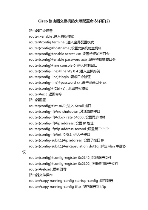
Cisco路由器交换机防火墙配置命令详解(2)路由器口令设置router>enable ;进入特权模式router#config terminal ;进入全局配置模式router(config)#hostname ;设置交换机的主机名router(config)#enable secret xxx ;设置特权加密口令router(config)#enable password xxb ;设置特权非密口令router(config)#line console 0 ;进入控制台口router(config-line)#line vty 0 4 ;进入虚拟终端router(config-line)#login ;要求口令验证router(config-line)#password xx ;设置登录口令xxrouter(config)#(Ctrl+z) ; 返回特权模式router#exit ;返回命令路由器配置router(config)#int s0/0 ;进入Serail接口router(config-if)#no shutdown ;激活当前接口router(config-if)#clock rate 64000 ;设置同步时钟router(config-if)#ip address ;设置IP地址router(config-if)#ip address second ;设置第二个IProuter(config-if)#int f0/0.1 ;进入子接口router(config-subif.1)#ip address ;设置子接口IProuter(config-subif.1)#encapsulation dot1q ;绑定vlan中继协议router(config)#config-register 0x2142 ;跳过配置文件router(config)#config-register 0x2102 ;正常使用配置文件router#reload ;重新引导路由器文件操作router#copy running-config startup-config ;保存配置router#copy running-config tftp ;保存配置到tftprouter#copy startup-config tftp ;开机配置存到tftp router#copy tftp flash: ;下传文件到flashrouter#copy tftp startup-config;下载配置文件ROM状态Ctrl+Break ;进入ROM监控状态rommon>confreg 0x2142 ;跳过配置文件rommon>confreg 0x2102 ;恢复配置文件rommon>reset;重新引导rommon>copy xmodem: flash: ;从console传输文件rommon>IP_ADDRESS=10.65.1.2 ;设置路由器IP rommon>IP_SUBNET_MASK=255.255.0.0 ;设置路由器掩码rommon>TFTP_SERVER=10.65.1.1 ;指定TFTP服务器IP rommon>TFTP_FILE=c2600.bin ;指定下载的文件rommon>tftpdnld ;从tftp下载rommon>dir flash: ;查看闪存内容rommon>boot ;引导IOS。
CTOCISCO防火墙配置实例

本人在项目中已经两次接触到思科5500系列防火墙的配置应用了;根据项目的需求不同;详细的配置也不一样;因此汇总了一个通用版本的思科5500系列防火墙的配置;不详之处;请各位大虾给予指点;谢谢CD-ASA5520#showrun:Saved:ASAVersion7.22hostnameCD-ASA5520 //给防火墙命名domain-name //定义工作域enablepassword9jNfZuG3TC5tCVH0encrypted //进入特权模式的密码namesdns-guardinterfaceGigabitEthernet0/0 //内网接口:duplexfull //接口作工模式:全双工;半双;自适应nameifinside //为端口命名:内部接口insidesecurity-level100 //设置安全级别0~100值越大越安全ipaddress//设置本端口的IP地址interfaceGigabitEthernet0/1 //外网接口nameifoutside //为外部端口命名:外部接口outside security-level0ipaddress//IP地址配置interfaceGigabitEthernet0/2nameifdmzsecurity-level50ipaddressinterfaceGigabitEthernet0/3shutdownnonameifnosecurity-levelnoipaddressinterfaceManagement0/0 //防火墙管理地址shutdownnonameifnosecurity-levelnoipaddresspasswd2KFQnbNIdI.2KYOUencryptedftpmodepassiveclocktimezoneCST8dnsserver-groupDefaultDNSdomain-nameaccess-listoutside_permitextendedpermittcpanyinterfaceoutsideeq3389//访问控制列表access-listoutside_permitextendedpermittcpanyinterfaceoutsiderange3000030010 //允许外部任何用户可以访问outside接口的30000-30010的端口.. pagerlines24loggingenable //启动日志功能loggingasdminformationalmtuinside1500 内部最大传输单元为1500字节mtuoutside1500mtudmz1500iplocalpoolvpnclientmask//定义一个命名为vpnclient的IP地址池;为remote用户分配IP地址nofailovericmpunreachablerate-limit1burst-size1asdmimagedisk0:/asdm-522.binnoasdmhistoryenablearptimeout14400 //arp空闲时间为14400秒globaloutside1interface //由于没有配置NAT故这里是不允许内部用户上INTERNETstaticdmz;outsidetcpinterface3000030000netmask//端口映射可以解决内部要公布的服务太多;而申请公网IP少问题.. staticdmz;outsidetcpinterface3000130001netmask30002映射给外部30002端口上..staticdmz;outsidetcpinterface3000230002netmaskstaticdmz;outsidetcpinterface3000330003netmaskstaticdmz;outsidetcpinterface3000430004netmaskstaticdmz;outsidetcpinterface3000530005netmaskstaticdmz;outsidetcpinterface3000630006netmaskstaticdmz;outsidetcpinterface3000730007netmaskstaticdmz;outsidetcpinterface3000830008netmaskstaticdmz;outsidetcpinterface3000930009netmaskstaticdmz;outsidetcpinterface3001030010netmaskstaticdmz;outsidetcpinterface33893389netmaskaccess-groupoutside_permitininterfaceoutside//把outside_permit控制列表运用在外部接口的入口方向..routeoutside1 //定义一个默认路由..timeoutconn1:00:00half-closed0:10:00udp0:02:00icmp0:00:02timeoutsunrpc0:10:00h3230:05:00h2251:00:00mgcp0:05:00mgcp-pat0:05:00 timeoutsip0:30:00sip_media0:02:00sip-invite0:03:00sip-disconnect0:02:00 timeoutuauth0:05:00absolute------------定义一个命名为vpnclient的组策略-------------------------group-policyvpnclientinternal //创建一个内部的组策略.. group-policyvpnclientattributes //设置vpnclient组策略的参数wins-servervalue//定义WINS-SERVER的IP地址..dns-servervalue//定义dns-server的IP地址..vpn-idle-timeoutnone //终止连接时间设为默认值vpn-session-timeoutnone //会话超时采用默认值vpn-tunnel-protocolIPSec //定义通道使用协议为IPSEC.. split-tunnel-policytunnelspecified //定义..default-domainvaluecisco //定义默认域名为cisco------------定义一个命名为l2lvpn的组策略-------------------------group-policyl2lvpninternalgroup-policyl2lvpnattributeswins-servervaluedns-servervaluevpn-simultaneous-logins3vpn-idle-timeoutnonevpn-session-timeoutnonevpn-tunnel-protocolIPSecusernametestpasswordP4ttSyrm33SV8TYpencryptedprivilege0//创建一个远程访问用户来访问安全应用usernameciscopassword3USUcOPFUiMCO4Jkencrypted httpserverenable //启动HTTP服务httpinside //允许内部主机HTTP连接nosnmp-serverlocationnosnmp-servercontactsnmp-serverenabletrapssnmpauthenticationlinkuplinkdowncoldstart//snmp的默认配置cryptoipsectransform-setESP-DES-MD5esp-desesp-md5-hmac//配置转集定义了IPSC隧道使用的加密和信息完整性算法集合cryptodynamic-mapvpn_dyn_map10settransform-setESP-DES-MD5//为动态加密图条目定义传换集cryptomapoutside_map10ipsec-isakmpdynamicvpn_dyn_map//创建一个使用动态加密条目的加密图cryptomapoutside_mapinterfaceoutside//将outside_map加密图应用到outside端口------------配置IKE--------------cryptoisakmpenableoutside //在ostside接口启动ISAKMP cryptoisakmppolicy20 //isakmmp权值;值越小权值越高authenticationpre-share //指定同位体认证方法是共享密钥encryptiondes //指定加密算法hashmd5 //指定使用MD5散列算法group2 //指定diffie-hellman组2lifetime86400 //指定SA协商安全关联的生存时间cryptoisakmppolicy65535authenticationpre-shareencryptiondeshashmd5group2lifetime86400-------------调用组策略-----------------cryptoisakmpnat-traversal 20tunnel-groupDefaultL2LGroupgeneral-attributes//配置这个通道组的认证方法default-group-policyl2lvpn //指定默认组策略名称..tunnel-groupDefaultL2LGroupipsec-attributes //配置认证方法为IPSECpre-shared-key* //提供IKE连接的预共享密钥tunnel-groupvpnclienttypeipsec-ra //设置连接类型为远程访问..tunnel-groupvpnclientgeneral-attributes //配置这个通道组的认证方法address-poolvpnclient //定义所用的地址池default-group-policyvpnclient //定义默认组策略-----设置认证方式和共享密钥-------------tunnel-groupvpnclientipsec-attributes //配置认证方法为IPSECpre-shared-key* //提供IKE连接的预共享密钥telnettimeout5 //telnet超时设置sshoutside //允许外部通SSH访问防火墙sshtimeout60 //SSH连接超时设置consoletimeout0 //控制台超时设置dhcp-clientupdatednsserverbothdhcpddns//dhcp发布的DNSdhcpdaddressinside //向内网发布的地址池dhcpdenableinside //启动DHCP服务..class-mapinspection_defaultmatchdefault-inspection-trafficpolicy-maptypeinspectdnsmigrated_dns_map_1parametersmessage-lengthmaximum512policy-mapglobal_policyclassinspection_defaultinspectdnsmigrated_dns_map_1inspectftpinspecth323h225inspecth323ras inspectnetbiosinspectrshinspectrtspinspectskinnyinspectesmtpinspectsqlnetinspectsunrpcinspecttftpinspectsipinspectxdmcpservice-policyglobal_policyglobal prompthostnamecontext:end。
CISCO路由器配置命令详解及实例

CISCO路由器配置命令详解及实例目录CISCO路由器配置命令详解及实例................................................................................................ 第一章:路由器配置基础.................................................................................................................一、基本设置方式.....................................................................................................................二、命令状态.............................................................................................................................三、设置对话过程.....................................................................................................................四、常用命令.............................................................................................................................五、配置IP寻址 .......................................................................................................................六、配置静态路由..................................................................................................................... 第二章:广域网协议设置.................................................................................................................一、HDLC..................................................................................................................................二、PPP......................................................................................................................................三、.............................................................................................................................................四、Frame Relay ........................................................................................................................五. Cisco765M通过ISDN拨号上263.....................................................................................六、PSTN................................................................................................................................... 第三章:路由协议设置.....................................................................................................................一、RIP协议 .............................................................................................................................三、OSPF协议 ..........................................................................................................................四、重新分配路由.....................................................................................................................五、IPX协议设置 ..................................................................................................................... 第四章?:服务质量及访问控制.......................................................................................................一、协议优先级设置.................................................................................................................二、队列定制.............................................................................................................................三、访问控制............................................................................................................................. 第五章:虚拟局域网(VLAN)路由..............................................................................................一、虚拟局域网(VLAN)...........................................................................................................二、交换机间链路(ISL)协议...............................................................................................三、虚拟局域网(VLAN)路由实例...................................................................................... 第六章:知识参考.............................................................................................................................一、路由器初始化.....................................................................................................................二、IP分配................................................................................................................................第一章:路由器配置基础一、基本设置方式一般来说,可以用5种方式来设置路由器:1.Console口接终端或运行终端仿真软件的微机;2.AUX口接MODEM,通过电话线与远方的终端或运行终端仿真软件的微机相连;3.通过Ethernet上的TFTP服务器;4.通过Ethernet上的TELNET程序;5.通过Ethernet上的SNMP网管工作站。
- 1、下载文档前请自行甄别文档内容的完整性,平台不提供额外的编辑、内容补充、找答案等附加服务。
- 2、"仅部分预览"的文档,不可在线预览部分如存在完整性等问题,可反馈申请退款(可完整预览的文档不适用该条件!)。
- 3、如文档侵犯您的权益,请联系客服反馈,我们会尽快为您处理(人工客服工作时间:9:00-18:30)。
1 服务安全防护安装配置服务安全防护主要为防止DDoS攻击的清洗中心,该系统有两个安全组件,一个为Detector,负责监控流量发现攻击行为,另外一个为Guard为清洗中心,当Detctor 发现攻击行为,会通知Guard,Guard会驱动清洗流程,将攻击流量过滤掉,将安全流量送回服务器。
1.1 总体连接情况1.2 基础平台配置清洗中心是和其他网络基础设施进行联动来防护的,如图所示,本方案的基础设施包括电信互联网路由器Cisco 2801、铁通互联网路由器Cisco 7206、电信通互联网路由器Cisco 7507和外网的Cat 3550交换机。
1.2.1 交换机VLAN建立和端口划分建立VLAN信息及其端口如下如下VLAN Name Status Ports ---- -------------------------------- --------- -------------------------------532 VLAN0532 active533 VLAN0533 active538 VLAN0538 active587 VLAN0587 active600 VLAN0600 active603 GUARD active Fa0/45 1002 fddi-default act/unsup1003 token-ring-default act/unsup1004 fddinet-default act/unsup1005 trnet-default act/unsup2001 DianXinGuard active Fa0/32002 DianXinTongGuard active2003 TieTongGuard active Fa0/82008 RSPAN_VLAN active2011 DinXinNei active Fa0/152012 DianXinTongNei active Fa0/10, Fa0/13 2013 TieTongNei active Fa0/7, Fa0/14 2021 DianXingWai active Fa0/1, Fa0/48 2022 TieTongWai active Fa0/5, Fa0/6 2023 DianXinTongWai active Fa0/9, Fa0/12 1.2.2 各个路由器端口划分和IP配置电信路由器端口及IP地址设置信息interface FastEthernet0/0description To-Beijingdianxinip address xx.yy.3.2 255.255.255.252duplex autospeed auto!interface FastEthernet0/1description TO-NEIW ANGno ip addressduplex autospeed auto!interface FastEthernet0/1.2001 encapsulation dot1Q 2001ip address a.b.70.249 255.255.255.248 !interface FastEthernet0/1.2011 encapsulation dot1Q 2011ip address a.b.70.3 255.255.255.248 no ip redirectsno ip unreachablesno ip proxy-arp铁通路由器端口及IP地址配置信息interface FastEthernet1/0description TieTong_outsideip address c.d.113.12 255.255.255.240 duplex full!interface FastEthernet1/1description TieTong_insideip address c.d.114.3 255.255.255.248no ip redirectsno ip unreachablesno ip proxy-arpduplex full!interface FastEthernet4/0description TieTong_Guardip address c.d.113.249 255.255.255.248 duplex half电信通路由器端口及IP地址配置信息interface FastEthernet0/1/0description Connetion-to-ISPip address 172.30.30.10 255.255.255.252no ip redirectsno ip unreachablesip nat outsideip virtual-reassemblyip route-cache flowfull-duplex!interface FastEthernet0/1/1no ip addressip route-cache flowfull-duplex!interface FastEthernet0/1/1.2002 encapsulation dot1Q 2002ip address g.h.30.249 255.255.255.248 no ip redirectsno ip unreachablesno ip proxy-arpno snmp trap link-status!interface FastEthernet1/0/0ip address e.f.174.249 255.255.255.248ip route-cache flowfull-duplex1.3 清洗中心Guard的配置连接Guard显示器和键盘,用admin/rdadmin默认用户名和密码登陆Guard,首先进行基础信息配置,包括端口、IP地址设置。
首先进行端口规划,Guard有两个千兆光纤口作为数据口,有一个百兆电口作为管理端口。
1.3.1 基础信息配置端口规划为:百兆端口作为管理端口,Giga0端口为牵引流量端口,启用Trunk,子端口giga0.2011对应电信、giga0.2012对应电信通、giga0.2013对应铁通分别与相应的路由器互联,发送牵引路由。
Giga1作为回注端口,启用Trunk,子端口giga0.2001对应电信、giga0.2002对应电信通、giga0.2003对应铁通分别与相应的路由器互联,发送牵引路由。
具体配置信息如下:interface eth0ip address 10.128.0.206 255.255.255.0 mtu 1500no shutdownexitinterface giga0mtu 1500speed full 1000no shutdownexitinterface giga0.2011ip address a.b.70.4 255.255.255.248 mtu 1500no shutdownexitinterface giga0.2012ip address e.f.174.250 255.255.255.248 mtu 1500no shutdownexitinterface giga0.2013ip address c.d.114.4 255.255.255.248mtu 1500no shutdownexitinterface giga1mtu 1500speed full 1000no shutdownexitinterface giga1.2001ip address a.b.70.250 255.255.255.248 mtu 1500no shutdownexitinterface giga1.2002ip address 218.249.30.250 255.255.255.248mtu 1500no shutdownexitinterface giga1.2003ip address c.d.113.250 255.255.255.248mtu 1500no shutdown配置完成所有命令后,用reload进行设备重启,数据端口进行no shutdown操作后,要进行设备重启才能生效。
1.3.2 启用web管理和SSH管理配置web管理admin@ShenHua_Guard-conf#service wbmadmin@ShenHua_Guard-conf#permit wbm *配置SSH管理SSH服务是默认启动的。
admin@ShenHua_Guard-conf#permit SSH *1.3.3 配置默认网关/Proxy地址admin@ShenHua_Guard-conf#default-gateway 10.128.0.254admin@ShenHua_Guard-conf#proxy c.d.113.251admin@ShenHua_Guard-conf#proxy 218.249.30.251admin@ShenHua_Guard-conf#proxy a.b.70.2511.3.4 配置日期、时间admin@ShenHua_Guard-conf# date MMDDhhmm[[CC]YY][.ss]1.3.5 配置路由admin@ShenHua_Guard-conf#routerHello, this is zebra (version 0.93b).Copyright 1996-2002 Kunihiro Ishiguro.router> enrouter#sh run!router bgp 65535bgp router-id c.d.114.4redistribute guard /重分布guard路由到BGP,必须写neighbor c.d.113.249 remote-as 65535 /与铁通路由器建立BGP邻居neighbor c.d.113.249 description Connect_to_TieTong_Routerneighbor c.d.113.249 soft-reconfiguration inbound /启用软重启功能neighbor c.d.113.249 distribute-list nothing-in in/不允许路由器更新Guard路由neighbor c.d.113.249 route-map Guard-out out/增加重分布到铁通路由器BGP属性neighbor 218.249.30.249 remote-as 65535neighbor 218.249.30.249 description Connect_to_DianxinTong_Router neighbor 218.249.30.249 soft-reconfiguration inboundneighbor 218.249.30.249 distribute-list nothing-in inneighbor 218.249.30.249 route-map Guard-out outneighbor a.b.70.249 remote-as 65535neighbor a.b.70.249 description Connect_to_Dianxin_Routerneighbor a.b.70.249 soft-reconfiguration inboundneighbor a.b.70.249 distribute-list nothing-in inneighbor a.b.70.249 route-map Guard-out out!ip route 0.0.0.0/0 c.d.113.249 设置Guard缺省路由,设置与否均可ip route c.d.114.9/32 c.d.114.2 设置保护zone回注路由ip route a.b.70.9/32 a.b.70.2设置保护zone回注路由ip route e.f.174.159/32 e.f.174.253设置保护zone回注路由ip route e.f.174.171/32 e.f.174.253设置保护zone回注路由!route-map Guard-out permit 10set community no-export no-advertise 设置BGP属性,不出本AS 1.3.6 各个互联网路由器路由配置电信路由器BGP配置信息router bgp 65535bgp router-id a.b.70.249bgp log-neighbor-changesneighbor a.b.70.250 remote-as 65535neighbor a.b.70.250 description Connect_to_Guard!address-family ipv4neighbor a.b.70.250 activateneighbor a.b.70.250 soft-reconfiguration inboundno auto-summaryno synchronizationexit-address-family与Guard建立BGP邻居,一旦发生攻击,Guard利用BGP给路由器牵引路由。
