24-锲紧块-1130
AZM 415-11 11ZPKFE 24VAC DC 调整式金属门锁说明书
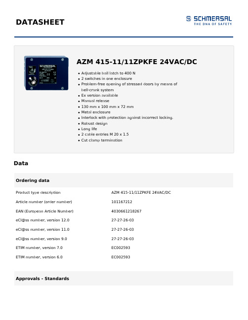
DATASHEETDataOrdering dataProduct type description AZM 415-11/11ZPKFE 24VAC/DC Article number (order number)101167212EAN (European Article Number)4030661218267eCl@ss number, version 12.027-27-26-03eCl@ss number, version 11.027-27-26-03eCl@ss number, version 9.027-27-26-03ETIM number, version 7.0EC002593ETIM number, version 6.0EC002593Approvals - StandardsCertificates BGCCCGeneral dataStandards BG-GS-ET-19EN IEC 60947-5-1 Working principle electromechanical Enclosure material Aluminium Enclosure coating material paintedGross weight962 gGeneral data - FeaturesPower to unlock YesManual release YesNumber of actuating directions1Number of auxiliary contacts2Number of safety contacts2Number of guard doors1Safety classificationStandards EN ISO 13849-1 Mission time20 Year(s)Safety classification - Safety outputsNormally-closed contact (NC)2,000,000 Operations B10DMechanical dataMechanical life, minimum1,000,000 OperationsHolding force FZh in accordance with EN ISO141193,500 NLatching force, minimum150 NLatching force, maximum400 NPositive break travel 5 mmPositive break force, minimum15 NActuating speed, maximum0.2 m/sMechanical data - Connection techniqueTermination Screw terminals M20 x 1.5Cable section, minimum 2 x 0.75 mm²Cable section, maximum 2 x 2.5 mm²Note (Cable section)All indications including the conductor ferrules.Mechanical data - DimensionsLength of sensor71.5 mmWidth of sensor130 mmHeight of sensor100 mmAmbient conditionsDegree of protection IP67Ambient temperature-25 ... +50 °CAmbient conditions - Insulation valuesRated insulation voltage Ui250 VACRated impulse withstand voltage Uimp4 kVElectrical dataThermal test current 6 ARated control voltage24 VAC/DCUtilisation category AC-15230 VACUtilisation category AC-15 4 AUtilisation category DC-1324 VDCUtilisation category DC-13 1 AElectrical power consumption, maximum10 WSwitching element NO contact, NC contactSwitching principle Slow actionMaterial of the contacts, electrical SilverOther dataNote (applications)sliding safety guardhinged safety guardNoteNote (Manual release)For manual release using M5 triangular key, available asaccessoryOnly used on units with power to unlock principleOrdering codeProduct type description:AZM 415-(1)(2)PK(3)-(4)(5)(6)-(7)(1)11/11 2 NC contacts/2 NO contacts11/02 3 NC contacts / 1 NO contacts11/20 1 NC contacts / 3 NO contacts02/11 3 NC contacts / 1 NO contacts02/20 2 NC contacts / 2 NO contacts02/02 4 NC contact(2)X Protection class IP54Z Protection class IP67(3)without Power to unlockA Power to lock(4)STR Connector M23 rightST Connector M23 bottom(5)without Without manual releaseE Manual release using triangular keyF with triangular key (secured with locking screw)FE using triangular keyRS Manual release using keyT Emergency exit using latched pushbutton (power tounlock only)TE Emergency exit using latched pushbutton and manualrelease, mounting outside (power to unlock only)TEI Emergency exit using latched pushbutton and manualrelease, mounting inside (power to unlock only)NS Emergency release using lock button(6)24VAC/DC Us: 24 VAC/DC110VAC Us: 110 VAC230VAC Us: 230 VAC(7)1637Gold-plated contacts(1)A Power to lock(2)ST Connector M23 rightwithout Power to unlockSTR Connector M23 bottom(3)without Without manual releaseE Manual release using triangular key (only for power tounlock principle)(4)1637Gold-plated contactsPicturesProduct picture (catalogue individual photo)ID: kazm4f25| 675.9 kB | .jpg | 352.778 x 279.753 mm - 1000 x 793 px - 72 dpi| 45.7 kB | .png | 74.083 x 58.561 mm - 210 x 166 px - 72 dpiDimensional drawing basic component| 35.2 kB | .cdr || 9.5 kB | .png | 74.083 x 51.506 mm - 210 x 146 px - 72 dpi| 132.1 kB | .jpg | 352.778 x 245.181 mm - 1000 x 695 px - 72 dpiDimensional drawing basic component| 28.2 kB | .cdr || 3.3 kB | .png | 74.083 x 51.506 mm - 210 x 146 px - 72 dpi| 74.3 kB | .jpg | 352.778 x 245.181 mm - 1000 x 695 px - 72 dpiDiagram| 59.7 kB | .ai | 297 x 210.002 mm - 841 x 595 px - 72 dpi| 80.4 kB | .jpg | 352.778 x 188.031 mm - 1000 x 533 px - 72 dpi| 3.6 kB | .png | 74.083 x 39.511 mm - 210 x 112 px - 72 dpiSchmersal, Inc., 15 Skyline Drive, Hawthorne, NY 10532The details and data referred to have been carefully checked. Images may diverge from original. Further technical data can be found in the manual. Technical amendments and errors possible.Generated on: 7/23/2023, 11:54 PM。
KYN-24(Z)铠装移开式交流金属封闭开关设备

各式手车
NVI-24断路器隔离手车电压互感器手车
主母线和联络母线为矩形截面的铜排;用于大电流负荷时采用双根母排拼联。
支母线通过螺栓联接于静触头盒和主母线,不需要其它支撑。
对于特殊需要,母线采用热缩套、联接螺栓绝缘套和端帽覆盖。
相邻柜母线用套管固定。
这样联接母线间所保留的空气缓冲,在如果出现内部故障电弧时,能防
6
主要电路方案图
7
产品安装尺寸图
8
产品安装地基图
9
订货须知
订货时应提供下列资料:
9.1 主结线方案编号及单线系统图,排列图及平面布置图;
9.2 二次接线图,端子排列图,若无端子排列图进按制造厂家端子排列图;
9.3 开关设备的电器元件的型号、规格、数量;
9.4 电气设备汇总表;
9.5 需要母线桥(两列柜间母线桥和墙柜间母线桥)时需提供跨距和高度尺寸;
9.6 开关设备使用在特别环境条件时在订货时提出;
9.7 需要其它或超出规定附件供应时提出种类和数量。
RCS-985RS_SS系列发电机保护装置技术和使用说明书

3.1 高性能硬件............................................................................................................................................ 4 3.2 主要保护原理性能 ................................................................................................................................ 4 3.3 智能化操作............................................................................................................................................ 6
6 保护原理 ...................................................................................................................................................... 14
5.1 硬件配置...............................................................................................................................................11 5.2 通道配置...............................................................................................................................................11 5.3 装置起动元件.......................................................................................................................................11 5.4 保护录波功能和事件报文 .................................................................................................................. 12
计算机网络设备报价单

块 台 台 台 个
4 1 4 40 2
1825 45000 9200 14500 12500
7300 H3C 45000 H3C 36800 H3C 623500 H3C 25000 H3C
规格、型号等特殊要求 2LC-2LC,50/125um OM3 LSS5120多模模块 LSQM1SUPA0
单位 条 个 个
数量 100 50 1
单价(元) 合价(元) 350 5500 27500
厂家
36190 德特威勒 522170 H3C 27500 H3C
SFP-XG-LX-SM1310 LinkManager-50NM-100N SFP-XG-SX-MM850-A
个 台 个
6 1 2
13700 78000 9950
82200 H3C 78000 H3C 19900 H3C
ቤተ መጻሕፍቲ ባይዱ
LSQM1GT24SC0
个
1
27000
27000 H3C
LSQM1GP48SC0 SecPath F1000-S-AI主机 LSQM1FAB08B0 LSQM1TGS16SC0 RT-MSR3660 300W AC
序号 1 2 3
4 5 6
7
8 9 10 11 12 13
14 15 16 17 18
材料名称 交换机光纤 接插线 多模模块 专用主控制 引擎模块 SFP+ 万兆模 块 (1310nm,10k m,LC) 网管系统 SFP+ 万兆模 块 (850nm,300m ,LC) 24端口千兆 以太网电接 口模块 (RJ45) 48端口千兆/ 百兆以太网 光接口模块 (SFP,LC) 防火墙 交换网板,B 类 16端口万兆 以太网SFP+ 光接口模块 路由器 路由器ACPSR300-12A2 电源模块 防火墙 LSKM2150A交 流电源模块 以太网交换 机主机 24口接入交 换机 48口接入交 换机 交流电源模 块,2500W
西门子 NXGPro+ 控制系统手册_操作手册说明书
3.4
单元通讯的协议 ............................................................................................................ 36
3.5
NXGpro+ 高级安全 .......................................................................................................37
3.2
功率拓扑 ......................................................................................................................34
3.3
控制系统概述 ...............................................................................................................35
NXGPro+ 控制系统手册
NXGPro+ 控制系统手册
操作手册
AC
A5E50491925J
安全性信息
1
安全注意事项
2
控制系统简介
3
NXGPro+ 控制系统简介
4
硬件用户界面说明
5
参数配置/地址
6
运行控制系统
7
高级的操作功能
8
软件用户界面
9
运行软件
10
故障和报警检修
11
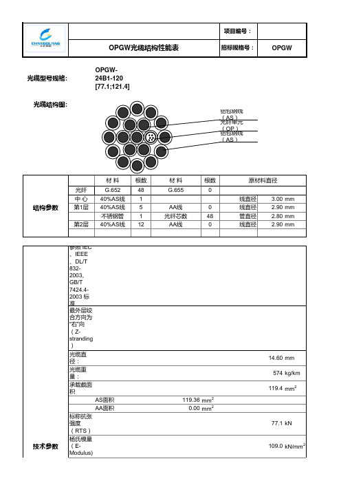
24B1-120结构图(承载截面,短路电流容量)
项目编号:
OPGW光缆结构性能表招标规格号:OPGW
光缆型号规格:OPGW-24B1-120 [77.1;121.4]
光缆结构图:
铝包钢线(AS)
光纤单元(OP)
铝包钢线(AS)
材料根数材料根数原材料直径
光纤G.65248G.6550
中心40%AS线1线直径 3.00mm
结构参数第1层40%AS线5AA线0线直径 2.90mm
不锈钢管1光纤芯数48管直径 2.80mm 第2层40%AS线12AA线0线直径 2.90mm
参照 IEC、IEEE、DL/T 832-2003、GB/T 7424.4-2003 标准
最外层绞合方向为“右”向(Z-stranding)
光缆直径:14.60mm
光缆重量:574kg/km
承载截面积119.4mm2
AS面积119.36mm2
AA面积0.00mm2
标称抗张强度(RTS)77.1kN
技术参数杨氏模量(E-Modulus)109.0kN/mm2热膨胀系数15.5×10-6/℃
最大允许工作应力 (MAT) ( 40% RTS)258.4N/mm2
每日应力(EDS) (18%~25% RTS)116.3~161.5N/mm2
极限特殊应力 (70% RTS)452.2N/mm2
直流电阻0.367Ω/km
短路电流(0.25s, 30℃~200℃)22.0kA
短路电流容量 I2t121.4kA2S
最小弯曲半径:施工:292mm
运行:219mm 拉重比13.7km 温度范围安装温度-10℃ ~ +50℃运输和运行温度-40℃ ~ +80℃注:所有尺寸和数据均为标称值。
HDMI矩阵用户手册
三、矩阵主机安装............................................................................................................................................. - 3 -
8.2 软件功能说明 ................................................................. - 12 8.2.1 主操作界面功能说明: ................................................................................................................. - 12 8.2.2 系统功能的应用 ......................................................................................................................... - 13 8.2.3 键盘切换功能的使用 ................................................................................................................. - 13 8.2.4 自动循环切换功能 ..................................................................................................................... - 14 8.2.5 手动输入指令 ............................................................................................................................. - 15 8.2.6 批量代码用户指令集 ................................................................................................................. - 15 8.2.7 收发指令列表 ............................................................................................................................. - 16 -
BQ24103A中文资料

4,5 mm x 3,5 mmActual SizeFEATURESDESCRIPTIONAPPLICATIONSUTUTVTS VSbq24100,bq24103,bq24103Abq24105,bq24108,bq24109bq24113,bq24113A,bq24115SLUS606K–JUNE2004–REVISED NOVEMBER2007 SYNCHRONOUS SWITCHMODE,LI-ION AND LI-POLYMER CHARGE-MANAGEMENT IC WITH INTEGRATED POWER FETs(bqSWITCHER™)•Ideal For Highly Efficient Charger Designs ForSingle-,Two-or Three-Cell Li-Ion and The bqSWITCHER™series are highly integrated Li-Polymer Battery Packs Li-ion and Li-polymer switch-mode chargemanagement devices targeted at a wide range of •Integrated Synchronous Fixed-Frequencyportable applications.The bqSWITCHER™series PWM Controller Operating at1.1MHz With0%offers integrated synchronous PWM controller and to100%Duty Cyclepower FETs,high-accuracy current and voltage •Integrated Power FETs For Up To2-A Charge regulation,charge preconditioning,charge status,and Rate charge termination,in a small,thermally enhancedQFN package.The system-controlled version •High-Accuracy Voltage and Current Regulationprovides additional inputs for full charge management •Available In Both Stand-Alone(Built-In Chargeunder system control.Management and Control)andSystem-Controlled(Under System Command)The bqSWITCHER charges the battery in threephases:conditioning,constant current,and constant Versionsvoltage.Charge is terminated based on user-•Status Outputs For LED or Host Processorselectable minimum current level.A programmable Interface Indicates Charge-In-Progress,Chargecharge timer provides a safety backup for charge Completion,Fault,and AC-Adapter Present termination.The bqSWITCHER automatically restarts Conditions the charge cycle if the battery voltage falls below an •20-V Maximum Voltage Rating on IN and OUT internal threshold.The bqSWITCHER automaticallyenters sleep mode when V CC supply is removed.Pins•High-Side Battery Current SensingRHL PACKAGE•Battery Temperature Monitoring(TOP VIEW)(bq24100,03,03A,05,08,09,13,13A,15)•Automatic Sleep Mode for Low PowerConsumption•System-Controlled Version Can Be Used InNiMH and NiCd Applications•Reverse Leakage Protection Prevents BatteryDrainage•Thermal Shutdown and Protection•Built-In Battery Detection•Available in20-Pin,3,5mm×4,5mm QFNPackage•Handheld Products•Portable Media Players•Industrial and Medical Equipment•Portable EquipmentPlease be aware that an important notice concerning availability,standard warranty,and use in critical applications ofTexas Instruments semiconductor products and disclaimers thereto appears at the end of this data sheet.bqSWITCHER,PowerPAD are trademarks of Texas Instruments.PRODUCTION DATA information is current as of publication date.Copyright©2004–2007,Texas Instruments Incorporated Products conform to specifications per the terms of the TexasABSOLUTE MAXIMUM RATINGS (1)bq24100,bq24103,bq24103A bq24105,bq24108,bq24109bq24113,bq24113A,bq24115SLUS606K–JUNE 2004–REVISED NOVEMBER 2007These devices have limited built-in ESD protection.The leads should be shorted together or the device placed in conductive foam during storage or handling to prevent electrostatic damage to the MOS gates.ORDERING INFORMATION (1)T JCHARGE REGULATION VOLTAGE (V)INTENDED APPLICATIONPART NUMBER (2)(3)MARKINGSbq24100RHLR CIA 4.2VStand-alone bq24100RHLT CIA bq24103RHLR CID 1or 2cells selectable (CELLS pin,4.2V or 8.4V)Stand-alone bq24103RHLT CID bq24103ARHLR CKO 1or 2cells selectable (CELLS pin,4.2V or 8.4V)Stand-alone bq24103ARHLT CKO bq24105RHLR CIF Externally programmable (2.1V to 15.5V)Stand-alonebq24105RHLT CIF –40°C to 125°Cbq24108RHLR CIU 4.2(Blinking status pins)Stand-alone bq24109RHLR CDY bq24113RHLR CIJ 1or 2cells selectable (CELLS pin,4.2V or 8.4V)System-controlled bq24113RHLT CIJ bq24113ARHLR CKF 1or 2cells selectable (CELLS pin,4.2V or 8.4V)System-controlled bq24113ARHLT CKF bq24115RHLR CIL Externally programmable (2.1V to 15.5V)System-controlled bq24115RHLTCIL(1)For the most current package and ordering information,see the Package Option Addendum at the end of this document,or see the TI Web site at .(2)The RHL package is available in the following options:T –taped and reeled in quantities of 250devices per reel R –taped and reeled in quantities of 3000devices per reel(3)This product is RoHS compatible,including a lead concentration that does not exceed 0.1%of total product weight,and is suitable for use in specified lead-free soldering processes.over operating free-air temperature range (unless otherwise noted)UNITSupply voltage range (with respect to V SS )IN,VCC20V STAT1,STAT2,PG,CE,CELLS,SNS,BAT –0.3V to 20V OUT–0.7V to 20VInput voltage range (with respect to V SS and PGND)CMODE,TS,TTC 7V VTSB 3.6V ISET1,ISET23.3V Voltage difference between SNS and BAT inputs (V SNS –V BAT )±1V Output sinkSTAT1,STAT2,PG 10mA Output current (average)OUT2.2A T A Operating free-air temperature range –40°C to 85°C T J Junction temperature range –40°C to 125°C T stgStorage temperature–65°C to 150°CLead temperature 1,6mm (1/16inch)from case for 10seconds300°C(1)Stresses beyond those listed under absolute maximum ratings may cause permanent damage to the device.These are stress ratings only,and functional operation of the device at these or any other conditions beyond those indicated under recommended operating conditions is not implied.Exposure to absolute-maximum-rated conditions for extended periods may affect device reliability.2Submit Documentation Feedback Copyright ©2004–2007,Texas Instruments IncorporatedPACKAGE DISSIPATION RATINGSRECOMMENDED OPERATING CONDITIONSELECTRICAL CHARACTERISTICSbq24100,bq24103,bq24103A bq24105,bq24108,bq24109bq24113,bq24113A,bq24115SLUS606K–JUNE 2004–REVISED NOVEMBER 2007T A <40°C DERATING FACTOR PACKAGE θJA θJC POWER RATINGABOVE T A =40°CRHL (1)46.87°C/W2.5°C/W1.81W0.021W/°C(1)This data is based on using the JEDEC High-K board,and the exposed die pad is connected to a copper pad on the board.This is connected to the ground plane by a 2x3via matrix.MINNOMMAX UNIT Supply voltage,V CC and IN (Tie together) 4.35(1)16(2)V Operating junction temperature range,T J –40125°C(1)The IC continues to operate below V min ,to 3.5V,but the specifications are not tested and not specified.(2)The inherent switching noise voltage spikes should not exceed the absolute maximum rating on either the IN or OUT pins.A tight layout minimizes switching noise.T J =0°C to 125°C and recommended supply voltage range (unless otherwise stated)Copyright ©2004–2007,Texas Instruments Incorporated Submit Documentation Feedback 3bq24100,bq24103,bq24103A bq24105,bq24108,bq24109bq24113,bq24113A,bq24115SLUS606K–JUNE 2004–REVISED NOVEMBER 2007ELECTRICAL CHARACTERISTICS (continued)T J =0°C to 125°C and recommended supply voltage range (unless otherwise stated)4Submit Documentation Feedback Copyright ©2004–2007,Texas Instruments Incorporatedbq24100,bq24103,bq24103Abq24105,bq24108,bq24109 bq24113,bq24113A,bq24115 SLUS606K–JUNE2004–REVISED NOVEMBER2007ELECTRICAL CHARACTERISTICS(continued)T J=0°C to125°C and recommended supply voltage range(unless otherwise stated)PARAMETER TEST CONDITIONS MIN TYP MAX UNITV CC≤V IBAT V CC≤V IBAT2.3V≤V I(OUT)≤V OREG,for1or2cells+5mV+75mVV SLP-ENT Sleep-mode entry threshold VV I(OUT)=12.6V,R IN=1kΩV CC≤V IBAT V CC≤V IBATbq24105/15(1)-4mV+73mVV SLP-EXIT Sleep-mode exit hysteresis, 2.3V≤V I(OUT)≤V OREG40160mVV CC decreasing below threshold,t FALL=100ns,10-mV overdrive,5µsPMOS turns offt dg-SLP Deglitch time for sleep modeV CC decreasing below threshold,t FALL=100ns,10-mV overdrive,203040msSTATx pins turn offUVLOV UVLO-ON IC active threshold voltage V CC rising 3.15 3.30 3.50V IC active hysteresis V CC falling120150mV PWM7V≤V CC≤V CC(max)400 Internal P-channel MOSFET on-resistance4.5V≤V CC≤7V500mΩ7V≤V CC≤V CC(max)130 Internal N-channel MOSFET on-resistance4.5V≤V CC≤7V150f OSC Oscillator frequency 1.1MHzFrequency accuracy–9%9%D MAX Maximum duty cycle100%D MIN Minimum duty cycle0%t TOD Switching delay time(turn on)20nst syncmin Minimum synchronous FET on time60nsSynchronous FET minimum current-off50400mA threshold(2)BATTERY DETECTIONBattery detection current during time-outI DETECT V I(BAT)<V OREG–V RCH2mAfaultI DISCHRG1Discharge current V SHORT<V I(BAT)<V OREG–V RCH400µAt DISCHRG1Discharge time V SHORT<V I(BAT)<V OREG–V RCH1sI WAKE Wake current V SHORT<V I(BAT)<V OREG–V RCH2mAt WAKE Wake time V SHORT<V I(BAT)<V OREG–V RCH0.5sBegins after termination detected,I DISCHRG2Termination discharge current400µAV I(BAT)≤V OREGt DISCHRG2Termination time262ms OUTPUT CAPACITORRequired output ceramic capacitor rangeC OUT from SNS to PGND,between inductor and 4.71047µFR SNSRequired SNS capacitor(ceramic)at SNSC SNS0.1µFpinPROTECTIONThreshold over V OREG to turn off P-channelV OVP OVP threshold voltage MOSFET,STAT1,and STAT2during charge110117121%V O(REG)or termination statesI LIMIT Cycle-by-cycle current limit 2.6 3.6 4.5AV SHORT Short-circuit voltage threshold,BAT V I(BAT)falling 1.952 2.05V/cellI SHORT Short-circuit current V I(BAT)≤V SHORT3565mAT SHTDWN Thermal trip165°C Thermal hysteresis10(1)For bq24105and bq24115only.R IN is connected between IN and PGND pins and needed to ensure sleep entry.(2)N-channel always turns on for~60ns and then turns off if current is too low.Copyright©2004–2007,Texas Instruments Incorporated Submit Documentation Feedback5bq24100,bq24103,bq24103A bq24105,bq24108,bq24109bq24113,bq24113A,bq24115SLUS606K–JUNE 2004–REVISED NOVEMBER 2007TERMINAL FUNCTIONSTERMINALbq24100,I/ODESCRIPTIONbq24103,bq24113,NAME bq24108,bq24105bq24115bq24103Abq24113Abq24109Battery voltage sense input.Bypass it with a 0.1µF capacitor to PGND if BAT 1414141414I there are long inductive leads to battery.Charger enable input.This active low input,if set high,suspends charge CE1616161616Iand places the device in the low-power sleep mode.Do not pull up this input to VTSB.Available on parts with fixed output voltage.Ground or float for single-cell CELLS 1313I operation (4.2V).For two-cell operation (8.4V)pull up this pin with a resistor to V CC .Charge mode selection:low for precharge as set by ISET2pin and high CMODE 77I (pull up to VTSB or <7V)for fast charge as set by ISET1.Output voltage analog feedback adjustment.Connect the output of aFB 1313I resistive voltage divider powered from the battery terminals to this node to adjust the output battery voltage regulation.IN 3,43,43,43,43,4I Charger input voltage.Charger current set point 1(fast charge).Use a resistor to ground to set ISET188888I/Othis value.Charge current set point 2(precharge and termination),set by a resistor connected to ground.A low-level CMODE signal selects the ISET2charge ISET299999I/O rate,but if the battery voltage reaches the regulation set point,bqSWITCHER changes to voltage regulation regardless of CMODE input.N/C 131919-No connection.This pin must be left floating in the application.11111O Charge current output inductor connection.Connect a zener TVS diode OUTbetween OUT pin and PGND pin to clamp the voltage spike to protect the 2020202020O power MOSFETs during abnormal conditions.Power-good status output (open drain).The transistor turns on when a PG 55555Ovalid V CC is detected.It is turned off in the sleep mode.PG can be used to drive a LED or communicate with a host processor.PGND 17,1817,1817,1817,1817,18Power ground inputCharge current-sense input.Battery current is sensed via the voltage drop SNS1515151515Ideveloped on this pin by an external sense resistor in series with the battery pack.A 0.1-µF capacitor to PGND is required.Charge status 1(open-drain output).When the transistor turns onSTAT122222Oindicates charge in process.When it is off and with the condition of STAT2indicates various charger conditions (See Table 1)Charge status 2(open-drain output).When the transistor turns onSTAT2191919Oindicates charge is done.When it is off and with the condition of STAT1indicates various charger conditions (See Table 1)Temperature sense input.This input monitors its voltage against an internal threshold to determine if charging is e an NTC TS 1212121212Ithermistor and a voltage divider powered from VTSB to develop this voltage.(See Figure 10)Timer and termination control.Connect a capacitor from this node to GND TTC 777I to set the bqSWITCHER timer.When this input is low,the timer and termination detection are disabled.VCC 66666IAnalog device input.A 0.1µF capacitor to VSS is required.VSS 1010101010Analog ground inputTS internal bias regulator voltage.Connect capacitor (with a value VTSB1111111111Obetween a 0.1-µF and 1-µF)between this output and VSS.There is an internal electrical connection between the exposed thermal pad and VSS.The exposed thermal pad must be connected to the same Exposed potential as the VSS pin on the printed circuit board.The power pad can Thermal Pad Pad Pad Pad Padbe used as a star ground connection between V SS and PGND.A common Padground plane may be used.VSS pin must be connected to ground at all times.6Submit Documentation Feedback Copyright ©2004–2007,Texas Instruments IncorporatedTYPICAL APPLICATION CIRCUITSbq24100,bq24103,bq24103A bq24105,bq24108,bq24109bq24113,bq24113A,bq24115SLUS606K–JUNE 2004–REVISED NOVEMBER 2007Figure 1.Stand-Alone 1-Cell ApplicationA.Zener diode not needed for bq24103A.Figure 2.Stand-Alone 2-Cell ApplicationCopyright ©2004–2007,Texas Instruments Incorporated Submit Documentation Feedback 7bq24100,bq24103,bq24103A bq24105,bq24108,bq24109bq24113,bq24113A,bq24115SLUS606K–JUNE 2004–REVISED NOVEMBER 2007TYPICAL APPLICATION CIRCUITS (continued)Figure 3.Stand-Alone 2-Cell ApplicationA.Zener diode not needed for bq24113A.Figure 4.System-Controlled Application8Submit Documentation Feedback Copyright ©2004–2007,Texas Instruments IncorporatedTYPICAL OPERATING PERFORMANCEI - Charge Current -A(BAT)E f f i c i e n c y - %800.511.5250607010090I - Charge Current -A(BAT)E f f i c i e n c y - %800.511.5250607010090bq24100,bq24103,bq24103A bq24105,bq24108,bq24109bq24113,bq24113A,bq24115SLUS606K–JUNE 2004–REVISED NOVEMBER 2007EFFICIENCYEFFICIENCYvsvsCHARGE CURRENTCHARGE CURRENTFigure 5.Figure 6.Copyright ©2004–2007,Texas Instruments Incorporated Submit Documentation Feedback 9*P a t e n t P e n d i n g #36889bq24100,bq24103,bq24103A bq24105,bq24108,bq24109bq24113,bq24113A,bq24115SLUS606K–JUNE 2004–REVISED NOVEMBER 2007FUNCTIONAL BLOCK DIAGRAM10Submit Documentation FeedbackCopyright ©2004–2007,Texas Instruments IncorporatedOPERATIONAL FLOW CHARTbq24113,bq24113A,bq24115SLUS606K–JUNE 2004–REVISED NOVEMBER 2007Figure 7.Stand-Alone Version Operational Flow Chartbq24113,bq24113A,bq24115SLUS606K–JUNE 2004–REVISED NOVEMBER 2007Figure 8.System-Controlled Operational Flow ChartDETAILED DESCRIPTIONUDG-04037V LOWRegulation VoltageRegulation CurrentV SHORTPrechargeand TerminationI SHORT PWM Controllerbq24113,bq24113A,bq24115 SLUS606K–JUNE2004–REVISED NOVEMBER2007The bqSWITCHER™supports a precision Li-ion or Li-polymer charging system for one-,two-,or three-cell applications.See Figure7and Figure8for a typical charge profile.Figure9.Typical Charging ProfileThe bq241xx provides an integrated fixed1MHz frequency voltage-mode controller with Feed-Forward function to regulate charge current or voltage.This type of controller is used to help improve line transient response, thereby simplifying the compensation network used for both continuous and discontinuous current conduction operation.The voltage and current loops are internally compensated using a Type-III compensation scheme that provides enough phase boost for stable operation,allowing the use of small ceramic capacitors with very low ESR.There is a0.5V offset on the bottom of the PWM ramp to allow the device to operate between0%to100% duty cycle.The internal PWM gate drive can directly control the internal PMOS and NMOS power MOSFETs.The high-side gate voltage swings from V CC(when off),to V CC-6(when on and V CC is greater than6V)to help reduce the conduction losses of the converter by enhancing the gate an extra volt beyond the standard5V.The low-side gate voltage swings from6V,to turn on the NMOS,down to PGND to turn it off.The bq241xx has two back to back common-drain P-MOSFETs on the high side.An input P-MOSFET prevents battery discharge when IN is lower than BAT.The second P-MOSFET behaves as the switching control FET,eliminating the need of a bootstrap capacitor.Cycle-by-cycle current limit is sensed through the internal high-side sense FET.The threshold is set to a nominal 3.6A peak current.The low-side FET also has a current limit that decides if the PWM Controller will operate in synchronous or non-synchronous mode.This threshold is set to100mA and it turns off the low-side NMOS before the current reverses,preventing the battery from discharging.Synchronous operation is used when the current of the low-side FET is greater than100mA to minimize power losses.Temperature QualificationRT1+VO(VTSB)VLTF*11RT2)1RTHCOLDRT2+V O(VTSB) RTH COLD RTH HOTƪ1VLTF*1VHTFƫRTH HOT ǒVO(VTSB)VHTF*1Ǔ*RTH COLDǒVO(VTSB)VLTF*1Ǔ(1)V (LTF)V (HTF)V (TCO)V SSV CCBattery Preconditioning (Precharge)bq24113,bq24113A,bq24115SLUS606K–JUNE 2004–REVISED NOVEMBER 2007The bqSWITCHER continuously monitors battery temperature by measuring the voltage between the TS pin and VSS pin.A negative temperature coefficient thermistor (NTC)and an external voltage divider typically develop this voltage.The bqSWITCHER compares this voltage against its internal thresholds to determine if charging is allowed.To initiate a charge cycle,the battery temperature must be within the V (LTF)-to-V (HTF)thresholds.If battery temperature is outside of this range,the bqSWITCHER suspends charge and waits until the battery temperature is within the V (LTF)-to-V (HTF)range.During the charge cycle (both precharge and fast charge),the battery temperature must be within the V (LTF)-to-V (TCO)thresholds.If battery temperature is outside of this range,the bqSWITCHER suspends charge and waits until the battery temperature is within the V (LTF)-to-V (HTF)range.The bqSWITCHER suspends charge by turning off the PWM and holding the timer value (i.e.,timers are not reset during a suspend condition).Note that the bias for the external resistor divider is provided from the VTSB output.Applying a constant voltage between the V (LTF)-to-V (HTF)thresholds to the TS pin disables the temperature-sensing feature.Figure 10.TS Pin ThresholdsOn power up,if the battery voltage is below the V LOWV threshold,the bqSWITCHER applies a precharge current,I PRECHG ,to the battery.This feature revives deeply discharged cells.The bqSWITCHER activates a safety timer,t PRECHG ,during the conditioning phase.If the V LOWV threshold is not reached within the timer period,the bqSWITCHER turns off the charger and enunciates FAULT on the STATx pins.In the case of a FAULT condition,the bqSWITCHER reduces the current to I DETECT .I DETECT is used to detect a battery replacement condition.Fault condition is cleared by POR or battery replacement.I O(PRECHG)+K (ISET2) V (ISET2)ǒR (ISET2) R (SNS)Ǔ(2)Battery Charge CurrentR (SNS)+V IREGI OCHARGE (3)R ISET1+K ISET1 V ISET1R SNS I CHARGE(4)Battery Voltage RegulationCharge Termination and RechargeI TERM +K (ISET2) V TERMǒR (ISET2) R (SNS)Ǔ(5)t CHARGE +C (TTC) K (TTC)(6)bq24113,bq24113A,bq24115SLUS606K–JUNE 2004–REVISED NOVEMBER 2007The magnitude of the precharge current,I O(PRECHG),is determined by the value of programming resistor,R (ISET2),connected to the ISET2pin.whereR SNS is the external current-sense resistor V (ISET2)is the output voltage of the ISET2pin K (ISET2)is the V/A gain factorV (ISET2)and K (ISET2)are specified in the Electrical Characteristics table.The battery charge current,I O(CHARGE),is established by setting the external sense resistor,R (SNS),and the resistor,R (ISET1),connected to the ISET1pin.In order to set the current,first choose R (SNS)based on the regulation threshold V IREG across this resistor.The best accuracy is achieved when the V IREG is between 100mV and 200mV.If the results is not a standard sense resistor value,choose the next larger ing the selected standardvalue,solve for V IREG .Once the sense resistor is selected,the ISET1resistor can be calculated using the following equation:The voltage regulation feedback occurs through the BAT pin.This input is tied directly to the positive side of the battery pack.The bqSWITCHER monitors the battery-pack voltage between the BAT and VSS pins.The bqSWITCHER is offered in a fixed single-cell voltage version (4.2V)and as a one-cell or two-cell version selected by the CELLS input.A low or floating input on the CELLS selects single-cell mode (4.2V)while a high-input through a resistor selects two-cell mode (8.4V).The bqSWITCHER monitors the charging current during the voltage regulation phase.Once the termination threshold,I TERM ,is detected,the bqSWITCHER terminates charge.The termination current level is selected by the value of programming resistor,R (ISET2),connected to the ISET2pin.whereR (SNS)is the external current-sense resistor V TERM is the output of the ISET2pin K (ISET2)is the A/V gain factorV TERM and K (ISET2)are specified in the Electrical Characteristics tableAs a safety backup,the bqSWITCHER also provides a programmable charge timer.The charge time is programmed by the value of a capacitor connected between the TTC pin and GND by the following formula:Sleep ModeCharge Status OutputsPG OutputCE Input (Charge Enable)bq24113,bq24113A,bq24115SLUS606K–JUNE 2004–REVISED NOVEMBER 2007whereC (TTC)is the capacitor connected to the TTC pin K (TTC)is the multiplier A new charge cycle is initiated when one of the following conditions is detected:•The battery voltage falls below the V RCH threshold.•Power-on reset (POR),if battery voltage is below the V RCH threshold •CE toggle•TTC pin,described as follows.In order to disable the charge termination and safety timer,the user can pull the TTC input below the V TTC_EN threshold.Going above this threshold enables the termination and safety timer features and also resets the timer.Tying TTC high disables the safety timer only.The bqSWITCHER enters the low-power sleep mode if the VCC pin is removed from the circuit.This feature prevents draining the battery during the absence of VCC.The open-drain STAT1and STAT2outputs indicate various charger operations as shown in Table 1.These status pins can be used to drive LEDs or communicate to the host processor.Note that OFF indicates that the open-drain transistor is turned off.Table 1.Status Pins SummaryCharge StateSTAT1STAT2Charge-in-progress ON OFF Charge completeOFF ON Charge suspend,timer fault,overvoltage,sleep mode,battery absentOFFOFFTable 2.Status Pins Summary (bq24108and bq24109only)Charge StateSTAT1STAT2Battery absent OFF OFF Charge-in-progress ON OFF Charge completeOFF ON Battery over discharge,V I(BAT)<V (SC)ON/OFF (0.5Hz)OFF Charge suspend (due to TS pin and internal thermal protection)ON/OFF (0.5Hz)OFF Precharge timer fault ON/OFF (0.5Hz)OFF Fast charge timer fault ON/OFF (0.5Hz)OFF Sleep modeOFFOFFThe open-drain PG (power good)indicates when the AC-to-DC adapter (i.e.,V CC )is present.The output turns on when sleep-mode exit threshold,V SLP-EXIT ,is detected.This output is turned off in the sleep mode.The PG pin can be used to drive an LED or communicate to the host processor.The CE digital input is used to disable or enable the charge process.A low-level signal on this pin enables the charge and a high-level V CC signal disables the charge.A high-to-low transition on this pin also resets all timers and fault conditions.Note that the CE pin cannot be pulled up to VTSB voltage.This may create power-up issues.Timer Fault RecoveryOutput Overvoltage Protection (Applies To All Versions)Functional Description for System-Controlled Version (bq2411x)Precharge And Fast-Charge ControlCharge Termination And Safety TimersInductor,Capacitor,and Sense Resistor Selection Guidelinesf 0+12p L OUT C OUTǸ(7)bq24113,bq24113A,bq24115SLUS606K–JUNE 2004–REVISED NOVEMBER 2007As shown in FIGURE 10,bqSWITCHER provides a recovery method to deal with timer fault conditions.The following summarizes this method.Condition 1V I(BAT)above recharge threshold (V OREG -V RCH )and timeout fault occurs.Recovery method:bqSWITCHER waits for the battery voltage to fall below the recharge threshold.This could happen as a result of a load on the battery,self-discharge or battery removal.Once the battery falls below the recharge threshold,the bqSWITCHER clears the fault and enters the battery absent detection routine.A POR or CE toggle also clears the fault.Condition 2Charge voltage below recharge threshold (V OREG –V RCH )and timeout fault occursRecovery method:Under this scenario,the bqSWITCHER applies the I DETECT current.This small current is used to detect a battery removal condition and remains on as long as the battery voltage stays below the recharge threshold.If the battery voltage goes above the recharge threshold,then the bqSWITCHER disables the I DETECT current and executes the recovery method described in Condition 1.Once the battery falls below the recharge threshold,the bqSWITCHER clears the fault and enters the battery absent detection routine.A POR or CE toggle also clears the fault.The bqSWITCHER provides a built-in overvoltage protection to protect the device and other components against damages if the battery voltage gets too high,as when the battery is suddenly removed.When an overvoltage condition is detected,this feature turns off the PWM and STATx pins.The fault is cleared once V IBAT drops to the recharge threshold (V OREG –V RCH ).For applications requiring charge management under the host system control,the bqSWITCHER (bq2411x)offers a number of control functions.The following section describes these functions.A low-level signal on the CMODE pin forces the bqSWITCHER to charge at the precharge rate set on the ISET2pin.A high-level signal forces charge at fast-charge rate as set by the ISET1pin.If the battery reaches the voltage regulation level,V OREG ,the bqSWITCHER transitions to voltage regulation phase regardless of the status of the CMODE input.The charge timers and termination are disabled in the system-controlled versions of the bqSWITCHER.The host system can use the CE input to enable or disable charge.When an overvoltage condition is detected,the charger process stops,and all power FETs are turned off.The bqSWITCHER provides internal loop compensation.With this scheme,best stability occurs when LC resonant frequency,f o is approximately 16kHz (8kHz to 32kHz).Equation 7can be used to calculate the value of the output inductor and capacitor.Table 3provides a summary of typical component values for various charge rates.Table 3.Output Components SummaryCHARGE CURRENT0.5A 1A 2A Output inductor,L OUT 22µH 10µH 4.7µHOutput capacitor,C OUT 4.7µF 10µF 22µF (or 2×10µH)ceramicSense resistor,R (SNS)0.2Ω0.1Ω0.05Ω。
标准紧固转矩
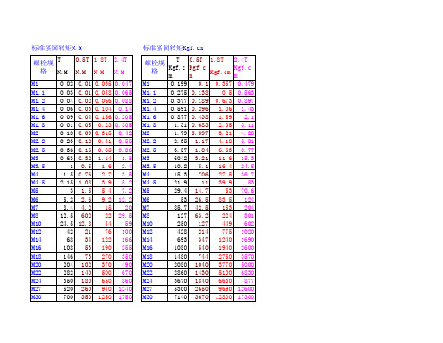
M30 M33 M36 M38 M42 M45 M48 M52 M58 M60 M64 M68
700 960 1240 1600 2000 2500 2960 3800 4500 5900 7200 8800
350 480 520 800 1000 1280 1500 1900 3400 2960 3600 4400
7140 9790 12600 16300 20400 25500 30100 38700 48900 60200 73400 8 4890 17500 23500 6320 22900 30600 8160 28600 38700 10200 36700 48900 12800 45900 61200 15300 54000 71400 19400 89300 93600 24500 87700 11800 30100 109000 14300 36700 133000 17800 44900 163000 2E+05
标准紧固转矩N.M 螺栓规格 M1 M1.1 M1.2 M1.4 M1.6 M1.8 M2 M2.2 M2.5 M3 M3.5 M4 M4.5 M5 M6 M7 M8 M10 M12 M14 M16 M18 M20 M22 M24 M27 T N.M 0.02 0.03 0.04 0.06 0.09 0.01 0.18 0.23 0.36 0.63 1 1.5 2.15 3 5.2 8.4 12.5 24.5 42 68 108 146 204 282 350 520 0.5T N.M 0.01 0.01 0.02 0.03 0.04 0.05 0.09 0.12 0.16 0.32 0.5 0.76 1.08 1.5 2.6 4.2 602 12.8 21 34 53 73 102 140 180 260 1.8T N.M 0.035 0.048 0.066 0.104 0.156 0.23 0.315 0.41 0.65 1.14 1.6 2.7 3.9 5.4 9.2 15 22 44 76 122 190 270 370 500 650 940 2.4T N.M 0.047 0.065 0.088 0.14 0.205 0.305 0.42 0.55 0.86 1.5 2.4 3.5 5.2 7.2 12.2 20 29.5 59 100 166 255 350 490 670 860 1240
新型沙漏金属点阵结构的力学性能与强化机理

摘要点阵结构不仅具有轻质和高承载特性,其互联互通的内部空间还可实现多功能开发,因此成为国际公认的最具前景的新一代轻质高强结构。
金字塔点阵结构在各方面都展现出优异性能,是目前人们关注最多、研究最广泛的一种点阵结构,然而,金字塔点阵结构仍然存在两个亟需解决的问题:一是,低相对密度下由于其杆件细长比较低,在压缩载荷下易发生杆件屈曲失效;二是,由于节点间距较大,在压缩载荷下易发生面板局部屈曲失效,在水下爆炸冲击载荷下易发生面板拉伸和撕裂破坏。
因此,本文旨在通过拓扑构型的设计,来克服以上缺陷,进而全面提升点阵结构力学性能。
本文基于金字塔点阵结构存在的上述问题,提出了一种新型沙漏点阵结构的拓扑构型设计方法。
相对于金字塔点阵结构,沙漏点阵结构不仅具有更大的杆件细长比,而且具有更小的节点间距,相应地,其杆件抗屈曲能力和面板抗局部屈曲能力得到增强。
本文通过简单且缺陷少的切割+嵌锁组装+真空钎焊工艺,对304不锈钢沙漏点阵结构进行了制备。
并对相对密度约为1.1%-2.7%的不锈钢沙漏点阵结构的面外压缩和面内剪切性能开展研究。
研究发现,当材料承受压缩载荷时,304不锈钢母材的压缩曲线预报模型比拉伸曲线预报模型更加准确,因此本文选择压缩模型进行理论预报。
研究发现,相比于相近相对密度金字塔点阵结构,沙漏点阵结构面外压缩强度提高了26%-47%,面内剪切强度提高约40%-60%。
这主要归功于沙漏点阵杆件抗屈曲能力的提升,说明这种沙漏点阵拓扑构型的设计能够显著提升夹芯结构芯子的力学性能。
同时,本文通过理论和实验方法对沙漏点阵结构的面内压缩和三点弯曲性能进行了研究,理论与实验吻合较好。
在面内压缩载荷下,沙漏点阵结构至少存在四种失效模式:宏观弹性屈曲、宏观非弹性屈曲、面板局部弹性屈曲和面板局部非弹性屈曲,根据这四种失效模式绘制了面内压缩载荷下的失效机制图。
分析失效机制图发现,沙漏点阵结构相比于金字塔点阵结构更不易发生面板局部屈曲失效。
科东纵向加密装置采购合同

科东纵向加密装置采购合同甲方(采购方):_____________________乙方(供应方):_____________________鉴于甲方需要采购科东纵向加密装置,乙方愿意提供该装置,双方本着平等互利的原则,经协商一致,订立本合同如下:第一条产品信息1. 产品名称:科东纵向加密装置2. 型号规格:____________________3. 数量:____________________4. 单价:____________________5. 总价:____________________6. 交货地点:____________________7. 交货时间:____________________8. 质量标准:____________________9. 技术参数:____________________10. 包装要求:____________________11. 售后服务:____________________12. 其他要求:_____________________第二条价格与支付方式1. 总价为人民币(大写):____________________2. 支付方式:____________________3. 付款时间:____________________4. 付款条件:____________________5. 逾期付款的违约责任:____________________6. 乙方提供发票:____________________7. 甲方付款前,乙方应提供相应的交付凭证:____________________8. 其他支付条款:_____________________第三条交货与验收1. 交货方式:____________________2. 交货时间:____________________3. 交货地点:____________________4. 验收标准:____________________5. 验收程序:____________________6. 验收期限:____________________7. 乙方逾期交货的违约责任:____________________8. 甲方逾期验收的违约责任:____________________9. 其他交货与验收条款:_____________________第四条质量保证与售后服务1. 质量保证期限:____________________2. 质量保证范围:____________________3. 售后服务内容:____________________4. 售后服务期限:____________________5. 售后服务方式:____________________6. 乙方对产品质量问题的响应时间:____________________7. 其他质量保证与售后服务条款:_____________________第五条违约责任1. 甲方违约责任:____________________2. 乙方违约责任:____________________3. 违约赔偿范围:____________________4. 违约赔偿计算方式:____________________5. 违约责任的免除条件:____________________6. 其他违约责任条款:_____________________第六条合同变更与解除1. 合同变更:____________________2. 合同解除:____________________3. 合同变更与解除的条件:____________________4. 合同变更与解除的程序:____________________5. 合同变更与解除后的权利义务:____________________6. 其他合同变更与解除条款:_____________________第七条争议解决1. 争议解决方式:____________________2. 争议解决地点:____________________3. 争议解决费用:____________________4. 其他争议解决条款:_____________________第八条其他1. 本合同自双方签字盖章之日起生效。
海阳AP1000核电站CB20模块十字焊缝及丁字焊缝焊接措施

海阳AP1000核电站CB20模块十字焊缝及丁字焊缝焊接措施【摘要】海阳AP1000核电站作为首批国家第三代核电技术的自主化依托项目,AP1000以其特有的非能动安全系统和模块化设计成为目前世界上最安全、最先进的核电技术。
CB20模块是非能动安全壳冷却水储存箱,是非能动安全壳冷却系统主要组成部分。
本文主要介绍了CB20模块中出现的大量十字焊缝及丁字焊缝现场拼装过程中的焊接控制措施。
【关键词】AP1000;CB20模块;十字焊缝;丁字焊缝1.前言十字焊缝接头形式导致焊缝交叉区域经历两次焊接热循环,接头热影响区中的粗晶区容易产生粗大及脆性组织;焊接是一个不均匀的局部加热过程,当焊件冷却至常温过程中,接头难以避免出现焊接残余应力,十字焊缝部位形成一个应力集中区域且容易产生焊接变形。
很多国内外标准中对十字焊缝做出了明确规定,如API 650-2007《钢制焊接石油储罐》5.1.5.2节b部分:相邻两层壁板的纵向接头不得在同一条直线上,相互错开的最小距离应为5t,其中,t为错开点处较厚板的厚度。
GB 50128-2005《立式圆筒形钢制焊接储罐施工及验收规范》3.2.1节:各圈壁板的纵焊缝宜向同一圈方向逐圈错开,相邻圈板纵缝间距宜为板长的1/3,且不应小于300mm。
因此,当现场无法避免或者施工图纸客观存在时,为了保证十字接头及丁字接头位置的焊接质量,应制定具体、有效的焊接措施来保证现场施工,控制焊接质量。
2.工程概况CB20 模块是截面为梯形的环形结构,外环直径25908mm,外环高度10292mm;内环直径10668mm,内环高度5486mm,底部锥体高度4806mm,单台机组总重量约302t,由112 个子模块焊接拼装而成,子模块主要由δ=1/2″和δ=3/4″的A240 S32101双相不锈钢板、A36 碳钢型钢等构成。
CB20模块安全等级为C级,抗震等级为I级,位于安全壳顶端,起到储存冷却水的作用,可以提供72小时2970立方冷却水,在发生设计基准事故时,通过重力,经水量分配装置,将冷却水均匀分配到安全壳外表面,保证安全壳内部不超过设计压力和温度。
基于ISA总线的纳秒级同步器的研制
基于ISA总线的纳秒级同步器的研制
党钊;李小群;陈骥;唐军
【期刊名称】《兵工自动化》
【年(卷),期】2004(023)006
【摘要】基于ISA总线的纳秒级同步器采用可编程硬件延时设计,其电路采用10片MC100E195级联,17位地址选择线通过并行接口8255控制门电路.晶振脉冲分频后经8254计数并产生基准信号,送可编程门阵列MC100E195,得到20ns级的延迟范围.采用VC++对同步器硬件端口探作,通过参数设置,得到多路延时同步信号.【总页数】2页(P72-73)
【作者】党钊;李小群;陈骥;唐军
【作者单位】中国工程物理研究院,激光聚变研究中心,四川,绵阳,621900;中国工程物理研究院,激光聚变研究中心,四川,绵阳,621900;中国工程物理研究院,激光聚变研究中心,四川,绵阳,621900;中国工程物理研究院,激光聚变研究中心,四川,绵
阳,621900
【正文语种】中文
【中图分类】TN347;TP336
【相关文献】
1.基于ISA总线的高压气瓶安全检测装置的研制 [J], 成曙;阳建红;陈飞;郑应强
2.基于ISA总线的电液伺服动静试验机控制器的研制 [J], 李健;张泳;石伟
3.基于ISA总线伺服控制卡的研制 [J], 闫如忠;陈云;方明伦;韩丰田
4.强干扰环境下微秒级脉冲磁场与纳秒级主机同步器的研制 [J], 樊亚军;石磊;邱爱慈;王永昌;朱妩娟
5.基于ISA总线的微秒级同步器研制 [J], 党钊;李小群;唐军;陈骥
因版权原因,仅展示原文概要,查看原文内容请购买。
圆锥滚子轴承预紧力控制方法
圆锥滚子轴承预紧力控制方法
李博溪;陈奇;朱衍飞;袁伟;高振宝;许灿
【期刊名称】《机械》
【年(卷),期】2012()S1
【摘要】轴承预紧力是决定轴承承载能力和运行质量的重要参数。
首先给出三种常用预紧方法,然后分析预紧力测量的两种方法,最后讨论预紧力调整和控制方法,并提出两种预紧力大小自动调整装置。
本文的研究为圆锥滚子轴承的设计和安装提供理论支持和应用参考。
?
【总页数】3页(P72-74)
【关键词】圆锥滚子轴承;预紧力;控制方法
【作者】李博溪;陈奇;朱衍飞;袁伟;高振宝;许灿
【作者单位】合肥工业大学机械与汽车工程学院
【正文语种】中文
【中图分类】TH11
【相关文献】
1.方法兼工具齐舞凯特克预紧力控制技术对渣油加氢装置反应器法兰的施工方案[J],
2.缸盖螺柱预紧力控制和把紧方法浅析 [J], 李刚;刘骞;曲传威;郭嘉琳;薛军
3.浅谈工程机械螺栓预紧力控制方法 [J], 郭连娣;赵兴虎;李柏松
4.现代飞机结构中螺栓预紧力控制方法探讨 [J], 朱虹;陈海龙;朱海兵;罗树东;朱远
见;谭一鸣
5.现代飞机结构中螺栓预紧力控制方法探讨 [J], 朱虹; 陈海龙; 朱海兵; 罗树东; 朱远见; 谭一鸣
因版权原因,仅展示原文概要,查看原文内容请购买。
单兵防弹插板防弹材料效应匹配及结构设计研究
单兵防弹插板防弹材料效应匹配及结构设计研究
王然;张燕;刘永佳;肖国江
【期刊名称】《中国新技术新产品》
【年(卷),期】2022()14
【摘要】该文针对单兵防护对高防护、轻量化的迫切需求,结合LS-DYNA软件仿真分析不同复合结构的防弹机理及损伤特征。
此外,结合53式7.62 mm穿甲燃烧弹的实测打靶验证仿真结果进行结构优化设计。
仿真结果表明,当复合结构为9.2 mm改性B_(4)C陶瓷+10.0 mmPE背板时,未穿透PE背板厚度最大。
实弹测试表明,亚微米减凸片具有优异的缓冲性能,能够明显降低防弹插板的背凸变形量;经过各单元材料匹配与结构设计,当结构为9.1 mm改性B_(4)C陶瓷+10.5 mmPE背板+5 mm亚微米减凸片时,防3发53式7.62 mm穿甲燃烧弹的性能较高。
【总页数】4页(P25-28)
【作者】王然;张燕;刘永佳;肖国江
【作者单位】北京普凡防护科技有限公司
【正文语种】中文
【中图分类】TS941
【相关文献】
1.复合材料多功能防弹板防弹性能研究
2.单兵防弹衣对穿甲破片的防护效应研究
3.防弹陶瓷插板的应用性能研究
4.SiC和B4C防弹插板抗多发弹打击损伤特性研究
5.陶瓷/UHMWPE层合板/阻尼材料复合靶板防弹性能研究
因版权原因,仅展示原文概要,查看原文内容请购买。
