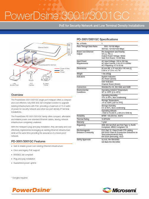
HER3001PTTOHER3008PT
奥康软起动器说明书

图形显示器
在许多情况下,我们不用文字,而是 用实时电机运行性能图和电流图快速 清晰地准确说明电机的运行情况。
远端显示器安装
操作板很容易采用任选的操作板安装 套件安装在机柜外面。如果在一个机 柜里安装多个软起动器,这样便于在 一个地方进行集中控制,可以获得所 有相关信息。也可以将多个显示器并 排安装在一起,迅速诊断问题。(安 装后的保护等级为IP65)。
2
XLR-8:自适应加速控制
XLR-8:自适应加速控制
AuCom新推出的EMX3软起动器采用全 新的软起动技术:XLR-8自适应加速控 制。XLR-8使你可以精确控制电机加速 曲线和减速曲线。
在使用XLR-8之后,软起动器可以在起 动和停止过程中了解电机性能,然后 调节控制器,达到优化性能的目的。 只需选择与负载类型相适应的曲线, 软起动器即可自动确保采用最平稳的 方式加速负载。
可以选择控制线从顶部、底部或左边走 线,非常灵活,独特的接线器和线槽可 使用EMX3是多么简单。
EMX3是易于使用的智能化可靠软起动 器。EMX3采用全新设计,非常适合快 速安装和定制控制,包括:
集特智能GS0-3001
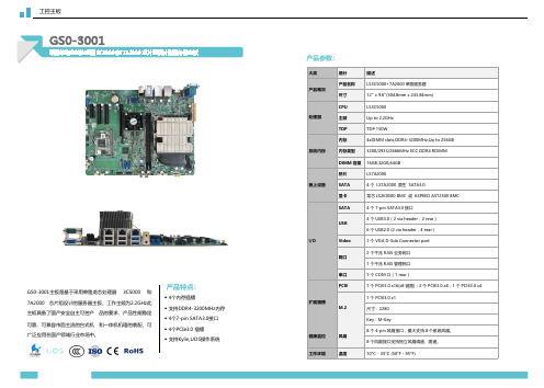
产品特点:
◆ 4个内存插槽 ◆ 支持DDR4-3200MHz内存 ◆ 4个7-pin SATA3.0接口 ◆ 4个PCIe3.0 插槽 ◆ 支持Kylin,UOS操作系统
产品参数:
大类 产品概况 处理器 系统内存 板上设备
I/O
扩展插槽 健康监控 工作环境
细分
描述
产品名称
LS3C5000+7A2000 单路服务器
桥片
LS7A2000
SATA
4 个 LS7A2000 原生 SATA3.0
显卡
龙芯 LS2K0500 BMC 或 ASPEED AST2500 BMC
SATA
4 个 7-pin SATA3.0 接口
USB
4 个 USB3.0(2 via header,2 rear) 6 个 USB2.0 (2 via header,4 rear)
尺寸
12'' x 9.6''(304.8mm x 243.84mm)
CPU
LS3C5000
主频
ቤተ መጻሕፍቲ ባይዱUp to 2.2GHz
TDP
TDP 150W
内存
4xDIMM slots,DDR4-3200MHz,Up to 256GB
内存类型
3200/2933/2666MHz ECC DDR4 RDIMM
DIMM 容量 16GB,32GB,64GB
工控主板
GS0-3001
采用单路龙芯处理器 3C5000 和 7A2000 芯片组设计的服务器主板
GS0-3001主板是基于采用单路龙芯处理器 3C5000 和 7A2000 芯片组设计的服务器主板,工作主频为2.2GHz此 主板具备了国产安全自主可控产 品的要求,产品性能稳定 可靠,可兼容市面主流的台式机 和一体机机箱的装配,可 广泛应用在国产领域行业市场中。
ARTISAN

390National Instruments • Tel: (800) 433-3488•Fax: (512) 683-9300•***********•C o u n t e r /T i m e r A c c e s s o r i e s a n d C a b l e sD a t a A c q u i s i t i o n a n d S i g n a l C o n d i t i o n i n gAccessory and Cable Selection ProcessStep 1.Select your counter/timer device from Tables 1 and 2.Step ing Tables 1 and 2 as a guide,determine which accessories are appropriate for that device.Select an accessory using Table 3 as reference.Step ing Tables 1 and 2,determine the appropriate cable solution for your selected counter/timer device and accessory.AccessoriesBNC-2121 (See Figure 1)Connector block with BNC and spring terminal connections for easy connection of I/O signals to counter/timer devices.The BNC-2121 offers spring terminals,as well as eight dedicated and six user-defined BNC connectors,which provide access to all I/O signals.This connector block is also a full-featured test accessory that provides pulse-train,trigger,and quadrature encoder signals.For the connections,refer to the BNC-2121 user guide at /manualsBNC-2121......................................................................................................778289-01Dimensions – 26.7 by 11.2 by 5.5 cm (8.0 by 4.4 by 2.2 in.)CA-1000 (See Figure 2)Configurable signal connectivity solution for connecting counter/timers to different types of standard I/O connectors.You can also incorporate switches and LED indicators.You can place the CA-1000 under a laptop PC,on a benchtop,or in a 19 in.rack.CA-1000......................................................................................................See page 351Dimensions – 30.7 by 25.4 by 4.3 cm (12.1 by 10 by 1.7 in.)Counter/Timer Accessories and CablesFigure 2. CA-1000 Configurable Signal Conditioning SolutionFigure 1. BNC-2121 Connector BlockAccessory DescriptionPage BNC-2121BNC connector block with built-in test features390CA-1000Configurable connector accessory 390SCB-68Shielded screw connector block 391TB-2715Front-mount terminal block for PXI-660x391TBX-68DIN-rail connector block 391CB-68LP Low-cost screw connector block 391CB-68LPR Low-cost screw connector block 391Table 1. Accessories and Cables for PXI-6601 and PCI-6602Table 2. Accessories and Cables for PXI-6602 and PXI-6608Table 3. Overview of AccessoriesPCI-6601, PCI-6602AccessoriesCables BNC-2121, CA-1000, SCB-68,–TBX-68, CB-68LP , and CB-68LPR R6868 or SH68-68-D1TB-2715N/APXI-6602, PXI-6608AccessoriesCables BNC-2121, CA-1000, SCB-68,–TBX-68, CB-68LP , and CB-68LPR R6868 or SH68-68-D1TB-2715Connects directly to the deviceCounter/Timer Accessories and CablesSCB-68 Shielded I/O Connector Block (See Figure 3)Shielded I/O connector block for easy connection of I/O signals to the counter/timer devices.T he screw terminals are housed in a metal enclosure for protection from noise bined with a shielded cable,the SCB-68 provides rugged,very low-noise signal termination.T he SCB-68 also includes two general-purpose breadboard areas.SCB-68..............................................................................................................776844-01Dimensions – 19.5 by 15.2 by 4.5 cm (7.7 by 6.0 by 1.8 in)TB-2715 Terminal Block (See Figure 4)With the T B-2715 terminal block for PXI counter/timer devices,you can connect signals directly without additional cables.Screw terminals provide easy connection of I/O signals.The TB-2715 latches to the front of your PXI module with locking screws and provides strain relief.TB-2715............................................................................................................778242-01Dimensions – 8.43 by 10.41 by 2.03 cm (3.32 by 4.1 by 0.8 in.)TBX-68 I/O Connector Block with DIN-Rail Mounting (See Figure 5)Termination accessory with 68 screw terminals for easy connection of field I/O signals to the counter/timer devices.The TBX-68 is mounted in a protective plastic base with hardware for mounting on a standard DIN rail.TBX-68..............................................................................................................777141-01Dimensions – 12.50 by 10.74 cm (4.92 by 4.23 in.)CB-68LP and CB-68LPR I/O Connector Blocks (See Figure 6)Low-cost termination accessories with 68 screw terminals for easy connection of field I/O signals to the counter/timer devices.The connector blocks include standoffs for use on a desktop or mounting in a custom panel.T he CB-68LP has a vertically mounted 68-pin connector.The CB-68LPR has a right-angle mounted connector for use with with the CA-1000.CB-68LP............................................................................................................777145-01Dimensions – 14.35 by 10.74 cm (5.65 by 4.23 in.)CB-68LPR ........................................................................................................777145-02Dimensions – 7.62 by 16.19 cm (3.00 by 6.36 in.)391National Instruments • Tel: (800) 433-3488•Fax: (512) 683-9300•***********•Counter/Timer Accessories and CablesData Acquisition andSignal ConditioningFigure 6. CB-68LP and CB-68LPR I/O Connector BlocksFigure 5. TBX-68 I/O Connector BlockFigure 4. TB-2715 I/O Terminal BlockFigure 3. SCB-68 Shielded I/O Connector Block392National Instruments • Tel: (800) 433-3488•Fax: (512) 683-9300•***********•C o u n t e r /T i m e r A c c e s s o r i e s a n d C a b l e sD a t a A c q u i s i t i o n a n d S i g n a l C o n d i t i o n i n gCablesRTSI Bus Cables (See Figures 7 and 8)Use RT SI bus cables to connect timing and synchronization signals among measurement,vision,motion,and CAN boards for PCI.For systems using long and short boards,order the extended RTSI cable.2 boards ..........................................................................................................776249-023 boards ..........................................................................................................776249-034 boards ..........................................................................................................776249-045 boards ..........................................................................................................776249-05Extended,5 boards ........................................................................................777562-05SH68-68-D1 Shielded Cable (See Figure 9)Shielded 68-conductor cable terminated with two 68-pin female 0.050 series D-type connectors.This cable connects counter/timer devices to accessories.1 m..................................................................................................................183432-012 m..................................................................................................................183432-02R6868 Ribbon I/O Cable (See Figure 10)68-conductor flat ribbon cable terminated with two 68-pin e this cable to connect the NI PCI-6601 to an accessory.For signal integrity with high-frequency signals,use the SH68-68-D1 with the NI 6602 and NI 6608.1 m..................................................................................................................182482-01Custom Connectivity Components68-Pin Custom Cable Connector/Backshell Kit (See Figure 11)68-pin female mating custom cable kit for use in making custom 68-conductor cables.Solder-cup contacts are available for soldering of cable wires to the connector.68-pin custom cable kit ................................................................................776832-01PCB Mounting ConnectorsPrinted circuit board (PCB) connectors for use in building custom accessories that connect to 68-conductor shielded and ribbon cables.Two connectors are available,one for right-angle and one for vertical mounting onto a PCB.68-pin,male,right-angle mounting..............................................................777600-0168-pin,male,vertical mounting....................................................................777601-01Counter/Timer Accessories and CablesFigure 10. R6868 Ribbon I/O CableFigure 9. SH68-68-D1 Shielded CableFigure 8. Extended RTSI Bus CableFigure 7. RTSI Bus CableFigure 11. 68-Pin Custom Cable Kit。
TA102系列双USB充电端口商品说明书
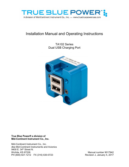
Installation Manual and Operating InstructionsTA102 SeriesDual USB Charging PortTrue Blue Power® a division ofMid-Continent Instrument Co., Inc.Mid-Continent Instrument Co., Inc.dba Mid-Continent Instruments and Avionics9400 E. 34th Street N.Wichita, KS 67226 Manual number 9017942FOREWORDThis manual provides information intended for use by persons who, in accordance with current regulatory requirements, are qualified to install this equipment. If further information is required, please contact:True Blue Powerc/o Mid-Continent Instrument Co., Inc.Attn: Customer Service Dept.9400 E. 34th Street N.Wichita, KS 67226 USAPH (316) 630-0101FX (316) 630-0723We welcome your comments concerning this manual. Although every effort has been made to keep it free of errors, some may occur. When reporting a specific problem, please describe it briefly and include the manual part number, the paragraph/figure/table reference and the page number. Send your comments to:True Blue Powerc/o Mid-Continent Instrument Co., Inc.Attn: Technical Publications9400 E. 34th Street N.Wichita, KS 67226 USAPH (316) 630-0101FX (316) 630-0723All products produced by Mid-Continent Instrument, Co., Inc., including those identified as Mid-Continent Instruments and Avionics or True Blue Power, are designed and manufactured in Wichita, KS, USA.©Copyright 2017Mid-Continent Instrument Co., Inc.REVISION HISTORYRev. Date Approved Detailrelease.A 04/19/13 BAW InitialB 05/30/13 BMC Updates driven by internal review.C 08/22/13 TKV Added Circular Rear Mount option and kit details, addedconfigurations -2, -3, and -4.D 11/1/13 TKV Added two additional pins to installation kit and informationregarding a recommended crimp tool.E 11/14/13 TKV Added information about adhesive for Front Mount Kit.Added information about ETSO certification.F 06/10/14 TKV Changed information about mounting screws. (PT+0.285”was PT+0.312”)G 02/26/15 TKV Added Modification Information, Added Mod 1H 09/12/16 CAS Changed the weight in ‘1.2.2 Physical Attributes’ to 0.13pounds.J 01/04/17 BAW Updated to include new mounting option. Added 1.2.4.TABLE OF CONTENTS SECTION 1 GENERAL DESCRIPTION1.1 INTRODUCTIONSPECIFICATIONS1.2 TECHNICAL1.2.1 ELECTRICAL ATTRIBUTES1.2.2 PHYSICAL ATTRIBUTES1.2.3 QUALIFICATIONS1.2.4 CONFIGURATIONSSECTION 2 PRE-INSTALLATION CONSIDERATIONS2.1 COOLINGLOCATION2.2 EQUIPMENTCABLES2.3 ROUTINGOF2.4 LIMITATIONS2.5 MODIFICATIONSSECTION 3 INSTALLATION PROCEDURESINFORMATION3.1 GENERAL3.2 UNPACKING AND INSPECTINGHARNESS3.3 CABLE3.3.1 WIRE GAUGE SELECTION3.3.2 PIN ASSIGNMENT INFORMATION3.3.3 HARNESS VERIFICATION3.4 MOUNTINGCOMPLETION3.5 INSTALLATIONSECTION 4 OPERATION4.1 ELECTRICALPERFORMANCEFEATURES4.2 PROTECTIVE4.2.1 SHORT CIRCUIT PROTECTION4.2.2 OVER-CURRENT PROTECTION4.2.3 LOW INPUT VOLTAGE SHUTDOWN4.2.4 OVER-TEMPERATURESECTION 5 CONFORMANCE5.1 CONTINUED AIRWORTHINESS STATEMENT5.2 ENVIRONMENTAL QUALIFICATION STATEMENTSECTION 1 GENERAL DESCRIPTION1.1 INTRODUCTIONThe TA102 Series Dual USB Charging Port is a certified accessory that converts 10 to 32 volts of DC electrical input from the aircraft to standard 5V power for any electronic product that charges using a USB connector. The TA102 provides two Universal Serial Bus-A (USB-A) ports and can be rear mounted or front mounted in a variety of locations throughout the aircraft. The unit is certified to FAA TSO C71 and qualified to multiple RTCA DO-160 requirements, providing confidence and convenience to be mounted in either the cabin or cockpit.This Dual USB Charging Port is designed as a DCP (Dedicated Charging Port) to industry-standard protocol per the USB Battery Charging 1.2 Compliance Plan. Early-generation or smaller consumer electronics typically accept one (1.0) amp of power during charging. However, newer electronics, such as the Apple iPad®, other tablets and larger devices can accept and, in some cases, require up to 2.1 amps of power to charge and operate. As a high power DCP, the TA102 can provide up to 2.1 amps of power to charge any USB device, including the higher demand products. Unlike most dual USB chargers which provide one (1.0) amp on one port and 2.1 amps on the second port, the TA102 can provide 2.1 amps of power to both ports simultaneously. With features like short circuit protection, over-current protection, low voltage shut-down and temperature monitoring, it can handle unforeseen conditions safely.Small, compact and powerful, with plenty of installation flexibility, the TA102 is an ideal choice when selecting a highly useful and effective addition for any aircraft.1.2 TECHNICALSPECIFICATIONS1.2.1 Electrical AttributesInput Voltage: 10-32 VDCInput Power: 24 watts max; 1.7 amps @ 14 VDC / 0.85 amps @ 28 VDC Output Voltage: 5 VDC ±0.25 per portOutput Power: 2.1 amps max per portEfficiency: ~85%nominalTable 1.11.2.2 Physical AttributesWeight: 0.13poundsDimensions: (not including connector) 1.50 inches wide X 1.50 inches high X 0.96 inches deep Charging Ports Type: USB Standard-AMounting: Panel mount; rear or frontTable 1.21.2.3 QualificationsCertification: FAATSO-C71EASA ETSO-C71Environmental Qualification: (see section 5.2) RTCA DO-160G Environmental CategoryF1S2BB[(RCC1)(UG)]XXXXXXY[B(XX)]BRXXMXXXAX Table 1.31.2.4 ConfigurationsPart Number Power Input USB Connector6430102-1 Rear Sealed6430102-2 Bottom Sealed6430102-3 Rear Lighted6430102-4 Bottom LightedTable 1.4SECTION 2 PRE-INSTALLATION CONSIDERATIONS2.1 COOLINGNo external cooling is required. The unit will become warm when in use. This is normal and within operational parameters. No special mounting considerations are required; however, mounting to a metal surface can help dissipate any heat generated and extend the life of the product.LOCATION2.2 EQUIPMENTThe TA102 Dual USB Charging Port is designed for mounting flexibility, allowing for installation in the cockpit or in the cabin. It is designed for panel mounting and can be installed in a rectangular or circular rear mount configuration or, with an available installation kit, can be front mounted with a cosmetic cover plate. An instrument mounting adapter bracket is also available to easily mount the unit in a standard 2-inch round instrument opening that may already exist in the cockpit panel. There are two versions to choose from which allow the input connector to be located either on the rear of the unit or from the bottom.The unit can be mounted in any orientation. Clearance should be provided for the mating connector which may require an additional inch beyond the rear of the unit.OFCABLES2.3 ROUTINGAvoid sharp bends in cabling and routing near aircraft control cables. Avoid close proximity and contact with aircraft structures, avionics equipment or other obstructions that could chafe wires during flight and cause undesirable effects.2.4 LIMITATIONSEnvironmental qualifications were verified per RTCA DO-160, Revision G in lieu of those identified within the minimum performance standards (MPS) of the TSO.The conditions and tests for TSO approval of this article are minimum performance standards. Those installing this article, on or in a specific type or class of aircraft, must determine that the aircraft installation conditions are within the TSO standards, specification of the article and deviations as listed above. TSO articles must have separate approval for installation in an aircraft. The article may be installed only according to 14 CFR part 43 or the applicable airworthiness requirements.2.5 MODIFICATIONSEach model TA102 (part number 6430102-( )) has a nameplate that identifies the manufacturer, part number, description, certifications and technical specifications of the unit. It also includes the “MOD” or modification number representing notable changes in the hardware design of the unit. The following are descriptions of the current modification releases of the TA102 Dual USB Charging Port.MOD 0Modification (MOD) 0 is identified on the nameplate by the lack of marking on the MOD numbers 1 through 9 (i.e. 1-9 are visible).Mod 0 is the initial release of the TA102 Dual USB Charging Port.MOD 1Modification (MOD) 1 is identified on the nameplate by the marking/blacking out of MOD number 1 (i.e. 1 is not visible and 2-9 are visible see Figure 2.2 below for example).Mod 1 of the TA102 Dual USB Charging Port contains the following changes from MOD 0: -Main PC Board Thickness Changed to 0.062” (was 0.031”)MOD 0 MOD 1FIGURE 2.2Modification Nameplate ExamplesSECTION 3 INSTALLATION PROCEDURESINFORMATION3.1 GENERALThis section contains interconnect diagrams, mounting dimensions and other information pertaining to the installation of the TA102 Dual USB Charging Port. After installation of cabling and before installation of the equipment, ensure that power and ground are applied to the proper pins specified in Section 3.3.2, Pin Assignment Information.3.2 UNPACKING AND INSPECTING EQUIPMENTWhen unpacking this equipment, make a visual inspection for evidence of any damage that may have occurred during shipment. The following parts should be included:a. Dual USB Charging Port MCIA P/N 6430102-( )b. Installation Manual MCIA P/N 9017942c. Connector Kit MCIA P/N 9017960i. Mating Connector, 2-pinii. Pins (4) (2 required, 2 spares)iii. Screws, #4-40 x 1/4 flat-head (2)iv. Screws, #4-40 x 5/16 flat-head (2)Optional Equipment Available:a. Circular Rear Mount Installation Kit MCIA P/N 9017945b. Front Mount Installation Kit MCIA P/N 9017946c. Instrument Mount Adapter Kit MCIA P/N 9017947d. Rear Mount Installation Kit MCIA P/N 9017957Equipment Not Provided:a. Cable Harness Wire See Section 3.3.1 for specificationsb. Circuit Breaker Recommendation 2 amp (1 amp may be sufficient for 28V aircraft)(as needed per system requirements)HARNESS3.3 CABLEConstruct the cable harness following the instructions outlined below and per Figure 3.1.Refer to Section 2: Pre-Installation Considerations, for routing precautions.3.3.1 Wire Gauge SelectionUse of PTFE, ETFE, TFE, Teflon or Tefzel insulated wire is recommended for aircraft use.The wire harness should utilize 20-24 AWG stranded wire. Refer to table 3.1 below.Wire Gauge Wire Length20 AWG stranded wire 35 ft22 AWG stranded wire 22 ft24 AWG stranded wire 14 ftTable 3.1Wire Gauge and LengthNote: Pins should be crimped using Molex Hand Crimp Tool 63819-0000 (Preferred), 63811-2800 (obsolete) or 11-01-0200 (obsolete). See the Molex Hand Crimp Tool User Manual for crimpprocedures.3.3.2 Pin Assignment InformationINPUT POWER:Pin A (keyed) – Positive DC input +10 to 32 VDC powerPin B – Negative DC input / ground3.3.3 Harness VerificationWARNING:Failure to install aircraft power and ground wires in the propermating connector locations will permanently damage the unit.Once the cable harness is prepared, prior to connecting the TA102, activate the aircraft power bus and use a multimeter to verify that aircraft power and ground is supplied with appropriate voltage on the proper pins within the mating harness.3.4 MOUNTINGThe TA102 can be installed in one of four ways:∙ rear mount, rectangular ∙ rear mount, circular * ∙ instrument mount *∙ front mount, decorative bezel * ∙ rear mount, decorative bezel ** installation kit required. See Section 3.2, Optional Equipment Available for part number referencePrepare the panel cutout as shown in Figures 3.3, 3.4, 3.5 or 3.6 per the selected mounting option.∙ For Rectangular Rear Mount, Circular Rear Mount and Instrument Mount Installations countersinksin the panel for flat head screws are optional. However, flat head screws are provided for flush appearance. For Front and Rear Decorative Bezel Installations, countersinks in the panel are required.∙ For Rear Mount Installations:Mounting screws length MUST be between (PT + 0.150”) and (PT +0.260”). [PT = panel thickness] Mounting screws provided with the unit are 0.24” and 0.31” (accommodates 0.020” to 0.160” PT). For PT greater than 0.125, the USB connector will be below the surface of the panel (below flush). ∙ For Circular Rear Mount Installations:Mounting screws length MUST be between (PT + 0.200”) and (PT + 0.375”). [PT = panel thickness] Mounting screws provided with the Circular Rear Mount Install Kit are 0.438”. ∙ For Front Mount Installation: Maximum panel thickness is 0.25”.∙ For Rear Mount Installation with Decorative Bezel: Panel thickness greater than 0.065 will cause theUSB connector to be below the surface of the bezel (below flush).Figure 3.1Power InputPin A(6430102-2, -4)Pin BPin B Pin A(6430102-1, -3)2 plcs3.5 INSTALLATION COMPLETIONPrior to operating the unit in the aircraft, it is recommended to verify the output and functionality of the unit. In order to prevent accidental damage to other systems, it is not recommended to attach the output to other equipment prior to verification. Verify the output of the unit at the terminating end of the cable with a multimeter to ensure proper voltage and polarity. Once verified, installation can be completed and functionality should be checked.Figure 3.3Rear Mount InstallationPanel Cutout DetailFigure 3.5Instrument Mount InstallationStep 1: attach adapterplate to unitStep 2: attach adapter plate topanelFigure 3.4Circular Rear Mount InstallationFigure 3.6Front Mount InstallationStep 4: place unit throughpanel cutout. Tightenpawl screws (x2)Step 5: Peel adhesive backing, align pins onrear of cover plate into holes onmounting plate and press firmlyStep 1: installgrommetsStep 2: place screw throughmounting plate and into pawl latch (x2)Step 3: attach mountingplate to unitStep 2: attach unit to panelwith screws (x2)Step 1: installgrommetsStep 3: place adhesive (x2) on panel inlocations shown, and peel backingoff adhesiveStep 4: align pins on rear of cover plate intoholes in panel and press firmly.Figure 3.7Rear Mount Installation with CoverSECTION 4 OPERATIONPERFORMANCE4.1 ELECTRICALThe TA102 Series Dual USB Charging Port converts an aircraft (DC) input voltage within the range specified to a 5V (DC) output. This output power is applied to a dual USB-A connector in accordance with the USB Implementers Forum.The USB D+ and D- data lines communicate with the USB portable device to tell the device it is a dedicated charging port (DCP), capable of a higher current than a standard USB port. This allows the USB portable device to draw up to 2.1 Amps.The unit is designed as a DC-to-DC converter with a series switch on each output to regulate current applied to that output. Each series switch independently reduces the output current to a safe level if the USB portable device draws excess current, is shorted or has a fault.If the temperature of the TA102 becomes elevated due to a fault or excessive load, the device will seamlessly communicate with the USB portable device to lower the charge current. This allows the device to continue charging while the unit returns to a temperature within designed limits. When the temperature returns to a safe level the TA102 will automatically reestablish the higher charge current level with the device and continue charging.FEATURES4.2 PROTECTIVE4.2.1 Short Circuit ProtectionThe TA102 is capable of surviving a short circuit event without permanent damage. The unitgoes into an over-current condition so that the average current is significantly reduced andthe device is protected.4.2.2 Over-Current ProtectionThe TA102 monitors the current draw individually on each port. During an over-currentcondition the voltage is reduced. If the voltage falls below 3.8 VDC the output is turned off fora period of 12 seconds. The output is then checked for continued over-current conditionsevery 16 milliseconds. This condition is referred to as a hiccup mode. The device stays in thismode until the over-current condition is removed, then returns to normal operation.4.2.3 Low Input Voltage ShutdownIf the input voltage applied to the TA102 drops below 10 VDC the unit will shut down until theapplied voltage returns to a level within range.4.2.4 Over-TemperatureWhen the temperature of the TA102 becomes elevated, the unit communicates with the USBportable device to reduce the charge current output (1 amp limit). When the temperaturereturns to an acceptable level the unit automatically returns to a higher charge current asrequired (up to 2.1 amps).SECTION 5 CONFORMANCE5.1 CONTINUED AIRWORTHINESS STATEMENTNo periodic scheduled maintenance or calibration is necessary for continued airworthiness of the TA102 series Dual USB Charging Port. If the unit fails to perform to specifications, the unit must be removed and serviced by Mid-Continent Instruments and Avionics or their authorized designee.5.2 ENVIRONMENTALQUALIFICATIONSTATEMENTMODEL NUMBER: TA102 Series PART NUMBER: 6430102-( ) NOMENCLATURE: Dual USB Charging PortCERTIFICATION: FAA TSO-C71MANUFACTURER:True Blue Power, a division of Mid-Continent Instrument Co., Inc.ADDRESS:9400 E. 34th St. North, Wichita, KS 67226, USA.MANUFACTURERS SPECIFICATIONS:Minimum Performance Specifications: TS102 (03/2013), TDS102 (03/2013)___________________ Qualification Test Reports: QTR1401-1402, QTR1404-1408, QTR1415-1416_______________________ RTCA DO-160: Rev G, dtd 12/08/10 DATES TESTED: 03/2013-04/2013CONDITIONS SECTIONDESCRIPTION OF TESTTemperature and Altitude Low TemperatureHigh Temperature High Temperature Altitude44.5.14.5.34.5.44.6.1Category F1Operating Low Temp = -40°CShort Time Operating High Temp = +70°CNormal Operating High Temp = +55°CAltitude = 55K feetTemperature Variation 5 Category S2Humidity 6CategoryB Operational Shock and Crash Safety 7 Category BVibration 8FixedWing:Category R, Curves C, C1Helicopter: Category U, Curve G[(RCC1)(UG)]Explosion 9CategoryX Waterproofness 10CategoryXFluids 11CategoryX Sand and Dust 12 Category XFungus 13CategoryX Salt Spray 14 Category XMagnetic Effect 15 Category YPower Input 16 Category B(XX)Voltage Spike 17 Category BAudio Freq Conducted Susceptibility 18 CategoryRInduced Signal Susceptibility 19 Category XRadio Frequency Susceptibility 20 CategoryXEmission of Radio Frequency Energy 21 Category MLightning Induced Transient Susceptibility 22 Category XLightning Direct Effects 23 Category XIcing 24CategoryX ESD 25CategoryA Fire, Flammability 26 Category CREMARKS:Sections 4: Category F1 Continuous Operating Low Temperature (-20°C) performed at Short-time Low temperature (-40°C).。
GigaSPEED XL 3071E-B ETL Verified Category 6 U UTP
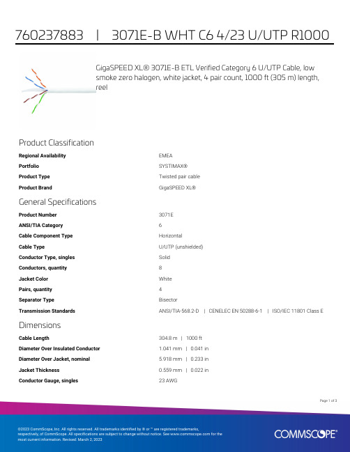
GigaSPEED XL® 3071E-B ETL Verified Category 6 U/UTP Cable, lowsmoke zero halogen, white jacket, 4 pair count, 1000 ft (305 m) length,reelProduct ClassificationRegional Availability EMEAPortfolio SYSTIMAX®Product Type Twisted pair cableProduct Brand GigaSPEED XL®General SpecificationsProduct Number3071EANSI/TIA Category6Cable Component Type HorizontalCable Type U/UTP (unshielded)Conductor Type, singles SolidConductors, quantity8Jacket Color WhitePairs, quantity4Separator Type BisectorTransmission Standards ANSI/TIA-568.2-D | CENELEC EN 50288-6-1 | ISO/IEC 11801 Class E DimensionsCable Length304.8 m | 1000 ftDiameter Over Insulated Conductor 1.041 mm | 0.041 inDiameter Over Jacket, nominal 5.918 mm | 0.233 inJacket Thickness0.559 mm | 0.022 inConductor Gauge, singles23 AWG13Page ofCross Section DrawingElectrical Specificationsdc Resistance Unbalance, maximum 5 %dc Resistance, maximum7.61 ohms/100 m | 2.32 ohms/100 ftDielectric Strength, minimum2500 VdcMutual Capacitance at Frequency 5.6 nF/100 m @ 1 kHzNominal Velocity of Propagation (NVP)70 %Operating Frequency, maximum300 MHzOperating Voltage, maximum80 VRemote Powering Fully complies with the recommendations set forth by IEEE 802.3bt (Type4) for the safe delivery of power over LAN cable when installed accordingto ISO/IEC 14763-2, CENELEC EN 50174-1, CENELEC EN 50174-2 or TIATSB-184-ASegregation Class cMaterial SpecificationsConductor Material Bare copperInsulation Material PolyolefinJacket Material Low Smoke Zero Halogen (LSZH)Separator Material PolyolefinPage of23Mechanical SpecificationsPulling Tension, maximum11.34 kg | 25 lbEnvironmental SpecificationsInstallation temperature0 °C to +60 °C (+32 °F to +140 °F)Operating Temperature-20 °C to +60 °C (-4 °F to +140 °F)Acid Gas Test Method EN 50267-2-3EN50575 CPR Cable EuroClass Fire Performance B2caEN50575 CPR Cable EuroClass Smoke Rating s1aEN50575 CPR Cable EuroClass Droplets Rating d0EN50575 CPR Cable EuroClass Acidity Rating a1Environmental Space Low Smoke Zero Halogen (LSZH)Smoke Test Method IEC 61034-2Packaging and WeightsCable weight38.097 kg/km | 25.6 lb/kftPackaging Type ReelRegulatory Compliance/CertificationsAgency ClassificationCENELEC EN 50575 compliant, Declaration of Performance (DoP) availableCHINA-ROHS Below maximum concentration valueISO 9001:2015Designed, manufactured and/or distributed under this quality management system REACH-SVHC Compliant as per SVHC revision on /ProductCompliance ROHSCompliantPage of33。
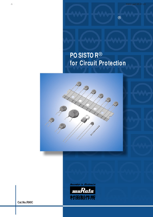
电路保护用正温度系数(PTC)热敏电阻
b
电流 (对数)
c
E
RL
a
I
A
I
=
E - Vp RL
B
电压 (对数)
E
[保护门限电流范围]
1000
电流 (mA)
800 跳闸电流
600 保护门限电流
400 不工作电流
200
0 -20
0 20 40 60 周围温度 (℃)
[工作电流]
I0
I0 2
电流 (A)
R90C.pdf 05.07.22
目录
1
本产品目录中的POSISTORr 与“POSISTOR”是村田制作所的注册商标。
品名表示法 POSISTORr 的基本特性 选择指南 用途一览表 1 过载电流保护用 片状型
片状型规格与测试方法
2 过载电流保护用 窄电流偏差 30V系列 3 过载电流保护用 窄电流偏差 51/60V系列 4 过载电流保护用 窄电流偏差 140V系列 5 过载电流保护用 24/30/32V系列 6 过载电流保护用 56/80V系列 7 过载电流保护用 125/140V系列 8 过载电流保护用 250/265V系列 PTGL系列窄电流偏差规格与测试方法 PTGL系列规格与测试方法 9 过热传感用 片状型 片状型 (仅供参考) 片状窄偏差型 (仅供参考) 片状型规格与测试方法 片状窄偏差型规格与测试方法 10 过热传感用 引线型
例如)
代码 470 471
电阻值 47Ω 470Ω
y电阻值允许偏差 代号 M Q
电阻值允许偏差 ±20%
特定允许偏差
u特殊规格 代号 B1
特殊规格 结构和其他
i包装 代号 RA RB RK
DS-3E0505和DS-3E0508系列吉伯特以太网开关用户手册说明书

23Symbol ConventionsThe symbols that may be found in this document are defined as follows.··During the installation and utilization of the device, please strictly conform to electrical safety rules in different nations and regions.·Ensure to use the attached power adaptor only and not to change the adaptor randomly. Please refer to specification table for specific requirements of power adaptor.·If the product does not work properly, please contact your dealer or the nearest service center. Never attempt to disassemble the camera yourself. (We shall not assume any responsibility for problems caused by unauthorized repair or maintenance.)·The device must be installed in machine room only, and only maintenance staff or qualified person should access to the device.·Do not touch the upper cover area of the device that may be overheated.·Power must be shut down during cable connection, device installation and dismantlement.·You shall acknowledge that the use of the device with Internet access might be under network security risks, please strengthen protection for your personal information and data security. If you find the device might be under network security risks, please contact with us.·Proper configuration of all passports and other security settings is the responsibility of the installer, and you shall keep user name and passports properly.·Please keep all original packing materials properly. If the product does not work properly, pack the switch in its original packing materials for shipping. We shall not assume any responsibility for damages caused by improper packing materials during shipping.45Device ConnectionInterfacesRear PanelGrounding TerminalThe grounding terminal is used to connect to the ground cable to protect the switch from lightning.Power SupplyUse the attached power cord to connect the switch to socket.Front PanelPacking List1Switch x 1Quick Start Guide x 1RJ45 Ports1000M Ethernet ports are used for devices connection via network cables .LINK/ACT Indicator RJ45 PortsIndicates a hazard with a high level of risk, which if not avoided, will result in death or serious injury.SymbolDescriptionProvides additional information to emphasize or supplement important points of the main text.Indicates a potentially hazardous situation, which if not avoided, could result in equipment damage, data loss, performance degradation, or unexpected results.PWR IndicatorGrounding TerminalPower SupplyDS-3E0505:DS-3E0508:LINK/ACT IndicatorRJ45 PortsDC 5V5/8-Port Gigabit Ethernet SwitchQuick Start GuidePower-On CheckingRegulatory InformationFCC InformationPlease take attention that changes or modification not expressly approved by the party responsible for compliance could void the user’s authority to operate the equipment.FCC compliance: This equipment has been tested and found to comply with the limits for a Class A digital device, pursuant to part 15 of the FCC Rules. These limits are designed to provide reasonable protection against harmful interference when the equipment is operated in a commercial environment. This equipment generates, uses, and can radiate radio frequency energy and, if not installed and used in accordance with the instruction manual, may cause harmful interference to radio communications. Operation of this equipment in a residential area is likely to cause harmful interference in which case the user will be required to correct the interference at his own expense.FCC ConditionsThis device complies with part 15 of the FCC Rules. Operation is subject to the following two conditions:1. This device may not cause harmful interference.2. This device must accept any interference received, including interference that may cause undesired operation.EU Conformity StatementThis product and - if applicable - the supplied accessories too are marked with "CE" and comply therefore with the applicable harmonized European standards listed under the EMC Directive 2014/30/EU, the LVD Directive 2014/35/EU,the RoHS Directive 2011/65/EU.2012/19/EU (WEEE directive): Products marked with this symbol cannot be disposed of as unsorted municipal waste in the European Union. For proper recycling, return this product to your local supplier upon the purchase of equivalent new equipment, or dispose of it at designated collection points.For more information see: 2006/66/EC (battery directive): This product contains a battery that cannot be disposed of as unsorted municipal waste in the European Union. See the product documentation for specific battery information. The battery is marked with this symbol, which may include lettering to indicate cadmium (Cd), lead (Pb),or mercury (Hg). For proper recycling, return the battery to your supplier or to a designated collection point. For more information see: Industry Canada ICES-003 ComplianceThis device meets the CAN ICES-3 (A)/NMB-3(A) standards requirements.See the following table and check whether your devices are correctly connected. After proper connection, you can use your switch without doing any settings.Please use the attached power cord in package to provide power to the The switch supports auto MDI/MDIX of ports, you can usestraight-through cable or crossover cable to connect the switch and opposite Ethernet devices.UD11864B6780100001080919Quick Start GuideALL RIGHTS RESERVED.Any and all information, including, among others, wordings, pictures, graphs are the properties of Hangzhou Hikvision Digital Technology Co., Ltd. or its subsidiaries (hereinafter referred to be “Hikvision”). This user manual (hereinafter referred to be “the Manual”) cannot be reproduced, changed, translated, or distributed, partially or wholly, by any means, without the prior written permission of Hikvision. Unless otherwise stipulated, Hikvision does not make any warranties, guarantees or representations, express or implied, regarding to the Manual.About this ManualThis Manual is applicable to DS-3E0105XX and DS-3E0109XX series 100M long-range PoE switch.The Manual includes instructions for using and managing the product. Pictures, charts, images and all other information hereinafter are for description and explanation only. The information contained in the Manual is subject to change, without notice, due to firmware updates or other reasons. Please find the latest version in the company website (/en/).Please use this user manual under the guidance of professionals.Trademarks Acknowledgementand other Hikvision’s trademarks and logos are the properties of Hikvision in various jurisdictions. Other trademarks and logos mentioned below are the properties of their respective owners.Legal DisclaimerTO THE MAXIMUM EXTENT PERMITTED BY APPLICABLE LAW, THE PRODUCT DESCRIBED, WITH ITS HARDWARE, SOFTWARE AND FIRMWARE, IS PROVIDED “AS IS”, WITH ALL FAULTS AND ERRORS, AND HIKVISION MAKES NO WARRANTIES, EXPRESS OR IMPLIED, INCLUDING WITHOUT LIMITATION, MERCHANTABILITY, SATISFACTORY QUALITY, FITNESS FOR A PARTICULAR PURPOSE, AND NON-INFRINGEMENT OF THIRD PARTY. IN NO EVENT WILL HIKVISION, ITS DIRECTORS, OFFICERS, EMPLOYEES, OR AGENTS BE LIABLE TO YOU FOR ANY SPECIAL, CONSEQUENTIAL, INCIDENTAL, OR INDIRECT DAMAGES, INCLUDING, AMONG OTHERS, DAMAGES FOR LOSS OF BUSINESS PROFITS, BUSINESS INTERRUPTION, OR LOSS OF DATA OR DOCUMENTATION, IN CONNECTION WITH THE USE OF THIS PRODUCT, EVEN IF HIKVISION HAS BEEN ADVISED OF THE POSSIBILITY OF SUCH DAMAGES.REGARDING TO THE PRODUCT WITH INTERNET ACCESS, THE USE OF PRODUCT SHALL BE WHOLLY AT YOUR OWN RISKS. HIKVISION SHALL NOT TAKE ANY RESPONSIBILITES FOR ABNORMAL OPERATION, PRIVACY LEAKAGE OR OTHER DAMAGES RESULTING FROM CYBER ATTACK, HACKER ATTACK, VIRUS INSPECTION, OR OTHER INTERNET SECURITY RISKS; HOWEVER, HIKVISION WILL PROVIDE TIMELY TECHNICAL SUPPORT IF REQUIRED.SURVEILLANCE LAWS VARY BY JURISDICTION. PLEASE CHECK ALL RELEVANT LAWS IN YOUR JURISDICTION BEFORE USING THIS PRODUCT IN ORDER TO ENSURE THAT YOUR USE CONFORMS THE APPLICABLE LAW. HIKVISION SHALL NOT BE LIABLE IN THE EVENT THAT THIS PRODUCT IS USED WITH ILLEGITIMATE PURPOSES.IN THE EVENT OF ANY CONFLICTS BETWEEN THIS MANUAL AND THE APPLICABLE LAW, THE LATER PREVAILS.。
Gavita Pro 1000e DE US 208-240 SL安装和使用说明书

line1 IntroductionThank you for purchasing the Gavita Pro 1000e DE US 208-240 SL. This manual describes the mounting and installing of the product and also describes how to use the product. Please read and understand this manual completely before using the product. Only use the product as specified in this manual.1.1 Used SymbolsWarning! A warning indicates severe damage to the user and/or product may occur when a procedure is not carried out as described.Caution! A caution sign indicates problems may occur if a procedure is not carried out as described. It may also serve as a reminder to the user.N ote: A note gives additional information, e.g. fo r a procedure.This symbol indicates that the reflector and lamp can reach very high temperatures (>85 °Celsius / >185 °Fahrenheit). Observe a cool down period before performing maintenance.This symbol is an internationally recognized symbol used to designate recyclable materials.This symbol is a certification mark employed on electronic products manufactured or sold in the United States which certifies that the electromagnetic interference from the device is under limits approved by the Federal Communications Commission.This symbol shows that a product has been independently tested and certified to meet recognized standards for safety. The symbol on the material, accessories or packaging indicates that this product may not be discarded as household waste. By disposing of the equipment in the proper way, you will be helping to prevent possible risks to the environment and public health, which might otherwise be caused by improper handling of the discarded equipment. Recycling of materials contributes to the conservation of natural resources. Therefore, please do not dispose of your old electronics and electrical appliances via household waste.T his symbol indicates the minimum distance (B) between the fixture (A) and the lit surface. 2 Product descriptionThe Gavita Pro 1000e DE US 208-240 SL is an adjustable horticultural fixture. The Gavita Pro 1000e DE US 208-240 SL can beused to drive a double ended 1000 W 400 V high frequency (electronic) high pressure sodium lamp.The Gavita Pro 1000e DE US 208-240 SL is an e-series product. It can be remotely switched and adjusted by a Gavita Master controller. The controller can automatically switch the fixture on and off during a 24 hour cycle.The controller also offers a temperature safety feature: auto-dimming or switching off connected fixtures when the temperature in a climate room becomes too high.The product can also be controlled by conventional timers in combination with a contactor. Make sure the dummy RJ plug sits in the IN port. If not, the fixture will not operate.In this manual, the Gavita Pro 1000eDE US 208-240 SL will be referred to as: “the fixture”.1000eDE US 208-240 SL3 Product information and specifications3.1 General product informationProduct name Pro 1000e DE US 208-240 SLManufacturer Gavita International bvEAN Code8718403054422Part number18.30.14.24.20Plug type Nema 6-153.2 Technical specificationsProduct weight8.4 lbs (3.8 kg)Dimensions (L*W*H)22.2”x9.7”x7.8” (56,5x24.5x19.5cm) (height excl. mounting hooks)Temperature case< 70 °Celsius / 158 °FahrenheitTemperature ambient0 ~ 35 °Celsius / 32 ~ 95 °FahrenheitInput voltage +/-10%208 V AC240 V ACInput current at 100% 5.2 A 4.5 AInput current at 115% 5.9 A 5.1 AMax current 6.8 AInput power at 100%1000 WInput power at 115%1236 WApparent power +/- 3%1082 VAPower factor0.97 - 0.99Relative humidity< 70% (not condensating)Total Harmonic Distortion< 10%Frequency50 - 60 HzCertification c CSA usInsulation Class 1 - requires an earth connectionPower inlet IEC C14Power output settings50 - 115%External control signal:RJ connector built in (6P6C)Ignition voltage: 5 kV / 600 msInrush current:≤ 40 AmpsInrush duration:1,6msEarth leakage current:≤ 1 mA3.3 Compatible products and accessoriesProduct name Gavita part numberCompatible controllers Gavita EL1 Master controller41.00.12.20 Gavita EL2 Master controller 41.00.13.20Replacement reflector Gavita HR96 DE30.46.13.00 Gavita MD 135 DE HC30.07.13.00 Gavita W 150 DE31.26.13.00Compatible lamps Gavita Pro Plus 1000 W EL DE HPS26.10.16.12 Compatible power cord Power cord US 240 V, 2.5 meter / 8.2 ft44.30.41.10 Compatible interconnect cable Interconnect cable RJ43.50.00.17Repeater bus connection kit43.50.10.003.4 EnvironmentThe product is intended to be used in greenhouses and climate rooms. The product can be used in damp environments. The product may not be used in wet environments or outdoors. The lamps function optimally when the ambient temperature is between 20 ~ 30°C / 68 ~ 86° Fahrenheit.3.5 LegalThis device complies with Part 18 of the FCC Rules.CSA approved.4 Safety recommendations and warningsWarning! Carefully read the warnings below before using or working with the product!• Always adhere to the local rules and regulations when installing or using the fixture.• Do not open or disassemble the fixture, it contains no servicable parts inside. Opening the fixture can be dangerous and will void the warranty.• This product may cause interference to radio equipment and should not be installed near maritime safety communications equipment or other critical navigation or communication equipment operating between 0.45 - 30 MHz.• Do not use the fixture when either its lamp or its power cord are damaged. Replace the power cord only with originalcertified cords. Replace the lamp only with lamps specified by Gavita (see paragraph 3.3).• The use of other lamps may damage the product and lamp and will void the warranty.• Modifications to the cords can lead to unwanted electromagnetic effects, which makes the product not comply with legal requirements.• Do not expose the fixture to:-condensing humidity, heavy mist, fog or direct spray;-(ambient) temperatures outside the specified range;-dust and contamination;-direct sunlight during use or HID light that could heat up the ballast.• Always disconnect the fixture from mains before performing any maintenance.• Always allow for a cool down period of at least 30 minutes before touching the lamp or reflector. Touching the lamp or the reflector when the lamp is lit or immediately afterwards will result in severe burns!• Never touch the lamp with bare hands as this will cause damage to the lamp.• Do not use the fixture near flammable, explosive or reactive substances. The lamp and the reflector of the fixture reach temperatures of >85 °Celsius / 185 °Fahrenheit.• Do not use sulfur vaporizers or water misters. Sulfur and calcium deposits on your reflector will decrease its efficiency.• The installation and use of the fixture is the responsibility of the end user. Incorrect use or installation can lead to failure and damage to the fixture. Damage to the fixture and electronic circuitry as a result of incorrect installation and use revokes the warranty.5 Contents (1)A. Pro 1000e DE US 208-240 SL fixture1. Electronic ballast2. Pro-line bracket3. Lever to unlatch reflector4. Lamp sockets5. Reflector Gavita HR96 DE*6. Mounting points*The reflector is delivery dependent,it may differ from the imageB. Gavita Pro 1000 W EL 400 V lampC. Interconnect cable (RJ/RJ )Cable length: 2.5 m / 8 ftD. Power cord with NEMA 6-15 plugE. Dummy6 Controls, connections andindications (2)A. IEC C14 connectionB. Gavita 2xRJ connector1. RJ IN2. RJ OUTC. Status LED7 InstallationW arning! Avoid coiled cords. Coiled cords may lead to electromagnetic interference.W arning! Always install the lamp before connecting the fixture to the mains.W arning! When connecting the fixture to the controller it may ignite. Make sure either power is disconnected or the controller is switched off.W arning! Ensure the local cabling can support the voltage and current requirements of the fixture.7.1 Preparing the fixture for use• Switch off mains power.• Install the lamp in the fixture (see paragraph 10.1).• Hang the lamp by its two mounting points (3). The mountingspoint are spaced 407 mm / 16 inches apart.1.2. Gavita 2xRJ NEMA6-157.2 Repeater bus connection kit (optional)The repeater bus connection kit contains the following items:1. 2 x EMC ferrite snap-on black bag (13x12x5x25.5x2.4)2. 4 x Gavita splitter 1 to 2 6P6C grey RJ25 (in bag)3. 8 x grey modular jack interconnect cable 6P6C RJ25 (in bag)4. 8 x SNAP-ON ferrite grey (in bag)5. Interconnect cable 6p 82 ft (25mtr) grey (in bag)7.3 Preparation for use with a controllerUsing a daisy chain setup, a maximum of 100 fixtures can be connected to one controller. Up to 500 fixtures per daisy chain can be connected when using splitters. See section 7.4 and 7.5 of this manual and the manual of the controller.• Take the unstripped black interconnect cable.• Cut the cable (supplied with controller) to the desired length and strip both ends using a crimp tool (5).• Insert the cable end in the RJ14 connectors (6) and use the crimp tool to finish the assembly.7.5 Connecting up to 500 or 1000 fixturesUsing a setup with daisy chained splitters, up to 500 fixtures on EL1 and 1000 fixtures on EL2 (over two channels) can be connected as shown in fig. 10.• Use the black controller cable (item comes with the controller) to connect the primary channel of the controller to the input port of the first splitter (10A).• Remove the dummy from the input port of the fixtures (8).N ote: Keep the dummy in a safe place! The dummy is necessary to operate the fixture in standalone mode.• Use a grey 6PC6 modular jack interconnect cable (item 3.) to connect the output port of the splitter to the input port of the first fixture (10C).• Use a grey 6PC6 modular jack interconnect cable (item 3.) to connect the output port of the first fixture to the input port of the second (10D).• Repeat these steps to connect up to 100 fixtures per splitter output port (10E). Up to 500 fixtures can be connected to the primary channel.• Snap-on two grey ferrite cores (item 4.) on the grey interconnect cable (item 3.) close to the 6P6C plugs.• Use the grey 6PC6 modular jack interconnect cables (item 3.) to connect the outport of a splitter to the inport of the next (10B).• Use the black secondary channel (item comes with controller) (10G) to connect another 500 fixtures, in the same way the fixtures are connected to the primary channel.Warning! Ensure the power cord and the controller cables do not touch any of the reflectors.Warning! Distribute number of fixtures evenly over daisy chains.Warning! Ensure the repeater bus connections are integrated in a correctly set up installation for best results.Warning! Boosters should never be used to expand.Warning! The maximum cable length per splitter is 250m (100 interconnect cables).7.6 Connecting the fixture to the mainsWarning! Ensure the cord is not coiled and does not touch any hot surfaces.W arning! If external switching gear is used to switch the fixture, ensure it can cope with the inrush current of the fixture (see paragraph 3.2). Always use a double pole contactor suitable of switching a capacitive load. Never use householdtimers to switch the fixture!• If a controller is used, ensure the controller is connected to the fixture.• Plug the power cord into the mains.• Switch on mains power.8 Product useWarning! Never use the fixture without a lamp or reflector!C aution! Before you dim or boost your HPS lamp, make sure that you run it at nominal value (100%) for at least 100 hoursto stabilize the lamp. Failing to do so may lead to sub-optimal light levels and premature end of life failure of your lamp.8.1 Using the controller to adjust the output of the lampThe output of the lamp is steplessly variable from 50-115% when connected to a controller. Consult the controller manual for more information on controlling the output of the lamp.9 Troubleshooting using the status LEDThe multi colour status LED provides information on the condition of the controller and the lamp. Consult table 1 and 2 to interpret the status LED. LED signals are represented by colored dots.- All operating modes include GREEN;- All warning codes include RED;- All history codes (except the ignition code) include ORANGE;- WARNINGS and history codes overrule operating mode display.9.1 Status indicationsStatus LED message Status fixture Description Action / SolutionNo power / off The fixture is not connected to themains or the power is off Check powerBallast stand-by Fixture is connected to the mains and to a controller. Output of ballast is offBallast on Fixture is connected to the mains and to a controller. Output of ballast is onFixture is ignitingthe lamp Fixture is trying to restart the lamp No action required. When lamp doesn’t start: Lamp too hot, defect or not properly connected (remote). Disconnect, check power cord and connections9.2 Error or warning indicationsStatus LED message Status fixture Description Action / Solution Too low voltage Input voltage is too low Check mains voltageToo low voltageoccured in past See above, resetToo high voltage Input voltage is too high Check input voltage, check wiring and connection, check neutral in 3 phase systemsToo high voltageoccured in past See above, resetToo hightemperatureElectronics temperature is too high(max. 115 °Celsius / 239 °Fahrenheit)Disconnect from mains. Checkinstallation, clean ballast, checkenvironment temperature(max 35 °Celsius / 95 °Fahrenheit). Makesure fixture is not heated by HPS lamplight. Wait untill the lamp is cooled down,then reconnect to mainsToo hightemperatureoccured in pastSee above, resetNo signal fromcontrollerFixture is connected to the mains andset to EXT but there is no signal on thecontrol input.If a controller is connected, search forloose connections, defect contacts orshort-circuits.Table 1 Table 210 Inspection, maintenance and repairW arning! Disconnect the product from mains before performing anymaintenance or repairs.W arning! Do not open or disassemble the fixture, it contains no servicable partsinside. Opening the fixture can be dangerous and will void the warranty.W arning! Always allow for a cool down period of at least 30 minutes beforetouching the lamp or reflector.C aution! Do not clean the fixture with detergents, abrasives or other agressivesubstances.C aution! Do not touch the inside of the reflector during installation and do notuse water, abrasives or detergents to clean it. This will damage the reflectivesurface.•Contamination may couse overheating and decreased performance.-Clean the inside of the reflector only with a soft, dry cloth;-cloth.•damaged lamp.N ote:when the lamp runs on full power. If not, replace the lamp.• Regularly check the wiring of the product to ensure it is undamaged.10.1 P lacement and replacement of the lampWtouching the lamp or reflector.CAlways use a fabric glove to handle the lamp.C aution! Only use lamps specified by Gavita (see paragraph 3.3).N ote:whichever one comes first.• Switch off mains power.•if the lamp is damaged.• Open the lamp holders by sliding them outwards (11).• Carefully take the lamp out of the fixture (12).••springs hold the lamp (13).• Close the lamp holders by sliding them inwards (14).• Switch on mains power.10.2 P lacement and replacement of the reflectorW arning! Always allow for a cool down period of at least 30 minutes beforetouching the lamp or reflector.N ote: Gavita recommends replacing the reflector* after 5000 lighting hours.Depending on the environment and contamination levels the reflector will degrade.The Vega/Miro™ aluminum can not be cleaned without damage. Therefore werecommend to change the reflector once every year. Also replace the lamp whenreplacing the reflector.* The reflector is delivery dependent, it may differ from the image.• Switch off mains power.• Remove the lamp from the fixture (see paragraph 10.1).• Support the reflector on the side of the reflector lever to prevent it from falling(15).• Move the reflector lever up to retract the two pins holding the reflector in place(16).• Remove the reflector (17).• Place the new reflector. Ensure the reflector lever is in the opened position toallow the reflector to pass.• Ensure the holes in the reflector are aligned with the pins in the fixture (18).• Release the reflector lever so its two pins hold the reflector in place.• Insert the lamp in the lamp holder (see paragraph 10.1).• Switch on mains power.11 Storage and disposal• Store the fixture in a dry and clean environment, with an ambient temperature of-20 ~ 85 °Celsius / -4 ~ 185 °Fahrenheit.• The product must not be discarded as unsorted municipal waste, but must becollected separately for the purpose of treatment, recovery and environmentallysound disposal.C aution! The lamps are chemical hazardous waste and must be delivered to thedesignated authorities.C aution! The lamp contains mercury.12 WarrantyGavita International bv warrants the mechanical and electronic components oftheir product to be free of defects in material and workmanship if used undernormal operating conditions for a period of three (3) years from the original date of purchase. If the product shows any defects within this period and that defect is not due to user error or improper use Gavita International bv shall, at its discretion,either replace or repair the product using suitable new or reconditioned products or parts. For HPS lamps the warranty period is one (1) year from the original date of purchase. In case Gavita International bv decides to replace the entire product, this limited warranty shall apply to the replacement product for the remaining initial warranty period, i.e. three (3) years from the date of purchase of the original product.For service return the fixture to your shop with the original sales receipt.GAVITA International bv Oosteinderweg 127 1432 AH Aalsmeer The Netherlands Tel : +31(0)297-380 450 Fax : +31(0)297-380 451 E :*************** W : Manual: Gavita Pro 1000e DE US 208-240 SL Changes reserved - Version 17/46。
AVer Document Camera Setup Guide

Setup your AVer Document Camera from home!Please first identify which AVer document camera you are using to know what software to install.A+ Suite (Sphere2 on Win10/Mac) or Sphere Lite (Chromebooks): AVer U70+, AVer U50, AVer M70HD, AVer 300AFHD, AVer F70W, AVer F50-8M, AVer F17-8M, M17-13MAVerTouch (Win10/Mac): AVer M15W, AVer M15-13M, AVer M70WA+ Interactive Software (Old Version on Win/Mac): V300AF ASIC, SPC300 ASIC, SPC300 +, CP130, CP150, CP300, SPB350, SPB370, CP135, CP155, CP355, V355AF, V310AF, SPB350+, V300AF+, F30, F50, U10, U15, AP20,M50, W30Sphere (Old Version on Win/Mac): PL50, SPB350, SPB370, SPB350+, M50, M70, V300AF+, F50, F30, F15 U15, W30A+ Suite (Sphere2):1.Download the A+ Suite software on your computer, go to:https:///education/support/aplus-suiteSelect the OS you are using to download the software (we will use Win10 in this tutorial)2.Open the downloaded .exe file to start the installationFollow the setup wizard to install the A+ Suite software3.After installation is completed, open the Sphere2 software4.Plug in the power adapter to your document camera and turn it on by pressing the power button (does notapply to U-series doc cams, your document camera may look different than the one pictured)5.Locate a USB port on your computer and connect your camera to it via USB cable that is included6.Select the visualizer icon on the top right of the Sphere2 software and select your camera7.You are now connected to your AVer document camera and can begin teaching!If you own an AVer F70W and wish to connect to your computer wirelessly, please follow this guide: https:///education/downloads/F70WV2-Quick-Guide-EN-v5-2020-02-24.pdfSphere Lite (Chromebook):1.Download the Sphere Lite software on your Chromebook, go to:https:///webstore/detail/sphere-lite/bhmibpbadaengbikmoglphhlhioajdjn?hl=enunch Sphere Lite app after installing3.Plug in the power adapter to your document camera and turn it on by pressing the power button (does notapply to U-series doc cams, your document camera may look different than the one pictured)4.Locate a USB port on your Chromebook and connect your camera to it via USB cable that is included5.Select your camera on the bottom left. You are now connected to your AVer document camera and can beginteaching!AVerTouch:1.Download the AVerTouch software on your computer, go to:https:///education/support/avertouchSelect the OS you are using to download the software (we will use Win10 in this tutorial)2.Unzip the downloaded .zip file3.Open the extracted folder and run the .exe to start the installation4.Follow the setup wizard to install the AVerTouch software5.After installation is completed, open the AVerTouch software6.Plug in the power adapter to your document camera and turn it on by pressing the power button (yourdocument camera may look different than the one pictured)7.Locate a USB port on your computer and connect your camera to it via USB cable that is includedNote: For M15W/M70W users, please make sure WiFi is turned off when trying to do a USB connection 8.The connected visualizer will appear within the AVerTouch software. Click the play icon to connect to thecameraIf you own an AVer M15W/M70W and wish to connect to your computer wirelessly, please follow this guide: M15W: https:///education/downloads/M15W-instruction-manual-EN-2019-12-20.pdfM70W: https:///education/downloads/M70W-instruction-manual-EN-v1-2019-12-20.pdfA+ Interactive Software:1.Download the A+ Interactive Software on your computer, go to:https:///education/support/averplusSelect the OS you are using to download the software2.Unzip the downloaded .zip file3.Open the extracted folder and run the .exe to start the installation4.Follow the setup wizard to install the A+ Interactive Software5.After installation is completed, open the A+ Interactive Software6.Power on and connect your doc cam to your computer via USB cable7.Select your visualizer within the software and you are now connected!Sphere:1.Download the Sphere on your computer, go to:https:///education/support/sphereSelect the OS you are using to download the software2.Run the downloaded .exe to start the installation3.Follow the setup wizard to install the Sphere software4.After installation is completed, open the Sphere Software5.Power on and connect your doc cam to your computer via USB cable6.Select your visualizer within the software and you are now connected!Using your AVer Document Camera with other platforms (Zoom, Skype, Google Hangout).Open up your software of choice and connect your AVer document camera to your computer via USB cable.Select your AVer document camera as your visualizer and you are successfully connected!(Please refer to Zoom, Skype, or Hangout user guides to navigate through their software)Zoom:https:///hc/en-us/articles/201362033-Getting-Started-on-Windows-and-MacSkype:https:///en/skype/windows-desktop/start/Hangout:https:///hangouts/?hl=en#topic=6386410Note: The following AVer doc cams are not UVC compliant and are not compatible with other platforms: F50, M70, PL50, W30, W30HD, Tabcam, 355AF, M50More HelpFor FAQs, technical support, software and instruction manual download, please visit:https:///education/support/Contact InformationAVer Information Inc.668 Mission Ct. Fremont, CA 94539, USAToll-free: 1(877)528-7824Local: 1(408)263-3828********************。
TEKPROBE BNC接口适用于P6204、P6205、P6217和P6231s激活FET探头的产

• Powers up to Two Probes
• For Use with: - 11000 Series Probes on NonTEKPROBETM Interfaced Scopes - P6203, P6204, P6205, P6217, P6231, P6245
• Overload Protected
Teldronix Distributor (see pages 59(}595).
Product(s) avalla~le through your local Tektronix representative (listed In the bac~ of this catalog) or call 1-800-426-2200.
.(809001
.NXillSIifl:I"',*~~
Tektronix M!lll$llf6ll1eRt products are m~ufaClureQ IR
ISO registered facilities.
P6205
• DC to 750 IVIHz • 2 pF Input C • 1 MQ Input R • Low Price
These Active Probes may also be used with 50 Q or 1 MQ oscilloscope systems, with conventional BNC interfaces, via the Tektronix 1103 TEKPROBETM Power Supply. The 1103 has dual TEKPROBpM inputs, dual BNC signal outputs, and dual voltage offset on/off switches and potentiometers.
TLS3001

典型应用:
单像素点光源 柔性灯带 护栏管 招牌字 条形屏
封装信息:
◆ ◆ ◆ ◆ SOP14 SSOP10 SOP8(仅应用于 5V 应用) 客户定制
2
TLS3001
3 通道 LED 恒流驱动芯片
功能框图
电气特性
最大限定范围
特性 电源电压 输入端电压(SDI) 输出端电流 输出端耐受电压 接地端电流 数据时钟频率 代表符号 VDD VIN IOUT VDS IGND FDCLK SOP14 承受功耗 PDmax SSOP10 SOP8 工作温度 存贮温度 Topr Tstg 最大工作范围 17 -0.4~Vcap+0.4 30 17 95 0.1~2 0.87 0.625 0.625 -45 ~ +85 -55 ~ +125 ℃ ℃ W 单位 V V mA V mA MHz
8
TLS3001
3 通道 LED 恒流驱动芯片
封装说明
SOP14 封装信息和管脚图
SOP14引脚分配定义 序号 1 2 3 4 5 Pin名称 VREF / NC VANA / NC SDI1 SDO2 OSC / NC 类型 输出 输出 输入 输出 输出 功能 测试端/未连接 测试端/未连接 串行数据输入端1 串行数据输出端2 测试端/未连接 外接电阻输入端,可调 6 VR 输入 节输出电流大小,默认 电阻为620Ω 7 8 9 10 11 12 13 14 GND CAP SDI2 SDO1 VDD OUT3 OUT2 OUT1 电源 输出 输入 输出 电源 输出 输出 输出 芯片地 外接1uF的稳压电容 串行数据输入端2 串行数据输出端1 芯片电源 恒流输出端,外接LED 恒流输出端,外接LED 恒流输出端,外接LED
IBM Security SiteProtector System SP3001 快速入门指南说明书

IBM Security SiteProtector System SP3001Quick Start Guide This document guides you through the process of connecting and performing the initial configuration of your IBM®Security SiteProtector System SP3001appliance.Front panelFront panel featuresv A:LCD panel-use for initial network configuration,restarting or shutting down the appliance,and viewing the serial number of the appliance.v B:Arrow and enter keys-use to select menu choices and interact with the appliance using the LCD panel.v C:Serial console RJ-45port-use for optional terminal-based setup,diagnostic testing,and recovery.v D:USB ports(3)-for keyboard,mouse,and external DVD-ROM to retrieve data and install firmware. v E:Indicators-to display status for alerts(amber),system ID(blue),and power(green)respectively.v F:Power switch-to power the unit on or off.v G:Management interfaces(2GbE NICs)-use Management port0to manage the SiteProtector appliance;management port1is unused.v H:VGA video port-for external monitor.Rear panelRear panel featuresv A:Cooling fans(3)v B:Cooling fan status(3)v C:Power connections(2)v D:Power supplies(4)Before you beginThe steps you perform in the remainder of this document will provide you with remote network access to the appliance so that you can perform more advanced configuration tasks.©Copyright IBM Corp.2009,20111You can find more advanced configuration information in the IBM Security SiteProtector System SP3001 Hardware Configuration Guide,available at the following URL:/infocenter/sprotect/v2r8m0/topic/com.ibm.siteprotector.doc/pdfs/sp_printable_pdfs.htmGather materialsYou must prepare some information and gather your equipment before you can install your SiteProtector appliance.U Materialsh IBM Security SiteProtector System SP3001applianceh Ethernet cable(included with appliance)h2power cords(included with appliance)Gather network informationUse this table to record important network information you need to configure the appliance:Settings Your SettingsIP Address(required)__________.__________.__________.__________Subnet Mask__________.__________.__________.__________Default Gateway__________.__________.__________.__________DNS Server__________.__________.__________.__________Host Name______________________________________________Gather operating system product keyUse this space to record the Product Key of the appliance's operating system.This Product Key can be found on the Certificate of Authenticity that is affixed to the appliance.You will need it in the event of a system restore.Product Key_________________________________________Gather SQL Server product key and tracking IDsUse this space to record the appliance's SQL Server license Product Key and Tracking IDs.The Product Key and Tracking IDs can be found on the Certificate of Authenticity that is affixed to the appliance or in the accessory box.You will need them in the event of an RMA return.Important:Save all the Product Key and Tracking ID information in a safe place.SQL Server Product Key_______________________________Tracking ID_________________________________________Tracking ID_________________________________________2SiteProtector SP3001:Quick Start GuideConnect the ApplianceFollow this procedure to connect and power up the SiteProtector appliance.Procedure1.Connect both power cords to the appliance to prevent warning signals from sounding.2.Connect the network to the management interface port0using the supplied Ethernet cable.Note thatmanagement port1should remain unused3.Turn on the appliance.The power button is located on the front of the appliance.4.When the LCD display reads"IBM Security SiteProtector SP3001,"proceed to Initial Configuration.Initial configurationEnter the network information you gathered earlier.Procedure1.Press Enter on the LCD panel."Appliance PIN"appears in the LCD menu.2.If you want to specify a personal identification number that users must enter to configure theappliance,press Enter,specify a4-digit number in the field provided,and then press Enter again.Note:Use the Up and Down buttons to specify digits and the Right and Leftbuttons to navigate between the fields.3.To configure the appliance to communicate with other devices,navigate to the Configuration menu(using the Up and Down buttons),then press the Enter button to begin the network configuration.Enter the information the same way you entered information in Step2.v IP Address(required)v Subnet Maskv Default Gatewayv DNS Serverv Host NameNote:Certain characters cannot be used in the Host Name.See the Microsoft article at/kb/909264for details on naming conventions.Note:A reboot occurs after you complete your network configuration.Next StepsInstall a ConsoleSelect a local workstation on which to install a SiteProtector Console.IBM Security SiteProtector System SP3001Quick Start Guide3Procedure1.From this local workstation,point a Web browser to the management address for the IBM Security SiteProtector System SP3001appliance:https://<configured address>:3994(for example:https://192.168.11.11:3994).2.Read and accept the End User License Agreement.The system then displays the IBM Security SiteProtector System SP3001home page with the following three links:v SiteProtector Web Accessv Install SiteProtector Consolev IBM Security3.Right-click the Install SiteProtector Console link,and then select Save/Run from the pop-up menu.4.Follow the steps on the installation wizard to install the SiteProtector Console on the local workstation.Launch Console and log inFollow these instructions to access the SiteProtector Console and log into it.Procedureunch the SiteProtector Console.2.Right-click the My Sites node in the left pane.3.Select New >Site .4.Enter the following information:OptionDescription ServerThe IP address configured during initial erAdministrator Password ISSADMINConfigure advanced settingsSee the IBM Security SiteProtector SP3001Hardware Configuration Guide for detailed information.Procedure1.Change the Administrative Password.2.Change the Database (SA)Password.Configure your SiteThe IBM Security SiteProtector System Configuration Guide walks you through other important tasks such as configuring your security policy,creating firewall rules to protect your network,tracking alerts,and monitoring important system information.Copyright statement©Copyright IBM Corporation Government Users Restricted Rights –Use,duplication or disclosure restricted by GSA ADP Schedule Contract with IBM Corp.(P) PN: 46N5772(2P) EC: L68311*2PL68311*(4L) Origin: SG Printed in Singapore *4LSG**P46N5772*4SiteProtector SP3001:Quick Start Guide。
CAP300 无线 AP 安装指南说明书

CAP300I. 產品資訊I-1. 包裝內容1. CAP300無線AP2. 吸頂安裝組件3. T 型導軌安裝組件及螺絲4. CD5. 安裝指南6. 網路線7. 12V DC 電源變壓器 8. 吸頂安裝螺絲對位圖I-2. 系統需求- 現有可對外連線了Cable/DSL 數據機或分享器 - 具瀏覽器功能的電腦可設定本產品7 8564123I-3. 硬體介面I-4. LED 指示燈網路線接埠電源變壓器接埠I-5. 恢復出廠預設值若您在使用本產品時遭遇問題,您可以將本產品的所有設定恢復至出廠預設值。
1.請按住機身後方的Reset鍵至少10秒鐘,再鬆開按鍵。
您可能會需要使用一枝鉛筆或一支迴紋針來按壓Reset按鍵。
2.請您稍待重新開機,待LED等轉為恆亮藍燈,即表示本產品已開機完成,您可以開始設定它。
II.快速安裝CAP300可以在很短的時間內開機完成並運作。
本安裝指南將導引您完成CAP300安裝及基本設定。
請依循下列章節指示:II-1. Initial Setup1.請使用網路線連接CAP300及您的電腦2.接著,請將包裝內附的12V DC變壓器連接CAP300,然後再將變壓器插入電源插座。
3.請稍待CAP300開機啟動,當LED燈轉為恆亮藍燈時,即表示開機已完成。
4.請將您電腦的IP位址更改為192.168.2.x (最後數字x為3-100的數字),若您不確定如何更改,請您參照使用手冊,查詢進一步的說明。
請確認您的電腦未連接任何其他執行中的網路(無線Wi-Fi連線或有連線的網路線都須中斷)5.請開啟瀏覽器並在網址列輸入192.168.2.26.接著,您會看到如下視窗,請您輸入預設使用者名稱”admin”及預設密碼” 1234”,輸入完成後,請點選OK確認。
7.進入系統資訊頁(如下圖示)。
8. 接著,請依循II-2.基本設定 說明,完成CAP300的基本設定。
II-2. 基本設定本章節說明可幫助您完成下列基本設定:- LAN IP 位址- 2.4GHz SSID 及安全設定 - 管理者名稱及密碼 - 時間與日期建議您在使用本產品之前,先完成基本設定。
PowerDsine 3001 3001GC 单口中间设备概述说明书
OverviewThe PowerDsine 3001/3001GC single port midspan offers a compact and cost effective, fully IEEE 802.3af compliant solution to upgrade existing infrastructures with PoE, providing a maximum of 15.4 watts of power for security network and other low port density IP terminal installations.The PowerDsine PD 3001/3001GC family offers compact, affordable and reliable power over standard Ethernet cables, leaving network infrastructure completely unaltered.With the midspan’s plug-and-play installation, they are easily and cost effectively implemented leveraging an existing Ethernet infrastructure while at the same time providing the assurance of a future proof network.PD-3001/3001GC Features• Safe & reliable power over existing Ethernet infrastructure • Cisco and legacy PoE support • IEEE802.3af compliant • Plug-and-play installation • Guaranteed power uptimePD-3001/3001GC SpecificationsNo. of Ports1Pass Through Data Rates 3001: 10/100 Mbps3001GC: 10/100/1000 Mbps Power over Ethernet Pin Assignment and Polarity:Output4/5 (+), 7/8 (–)Output Power Voltage: 48Vdc User Port Power: 15.4W Max.Input Power AC Input Voltage: 100 to 240 VacRequirements AC Input Current: 0.5A @110-220Vac AC Frequency: 47 to 63 HzDimensions 60 mm (W) x 31 mm (H) x 145 mm (L) 2.36 in. x 1.2 in. x 5.7 in Weight 1 lbs (450g) IndicatorsSystem Indicator:AC Power (Green)User Indicator:Channel Power (Green)Connectors Shielded RJ-45, EIA 568A and 568B Environmental Operating Ambient Temperature:Conditions32º to 104ºF (0 to 40ºC)Operating Humidity:10% to 90%, Non-condensing Storage Temperature: –4º to 158ºF (–20º to 70ºC)Storage Humidity:5% to 95%, Non-condensing Operating Altitude:–1000 to 10,000 ft. (–304.8 to 3048 m)Reliability MTBF: 100,000 hrs. @25ºC Thermal Rating 16 BTU/HrWarranty 1-yearRegulatoryIEEE 802.3af (PoE and PoH Type 1), RoHS Compliant, WEEE Compliant, CEElectromagneticFCC Part 15, Class B with FTP cablingEmission & ImmunityEN 55022 Class B (Conductive Emissions on Telecommunications Port) EN 55024 (Immunity), VCCI Safety ApprovalsUL/cUL Per EN 60950 GS Mark Per EN 60950UPSPTZ Camera LAN Access Point IP Video PhonePowerDsine® PD-3001GCEthernet SwitchPower & Data Data Power* Dongles requiredMicrosemi Corporation (NASDAQ:MSCC) offers the industry’s most comprehensive portfolio of semiconductor and networking technology. PowerDsine ® PoE Systems, a Microsemi brand, is the thought leader in energy efficient, high power PoE technology. Learn more at /powerdsinePower Matters.©2011 Microsemi Corporation. All rights reserved. Microsemi and the Microsemi logo are trademarks of Microsemi Corporation. All other trademarks and service marks are the property of their respective owners.MSC-PD-DS-3001-8.2011。
EP3001评估板手册说明书

1/4DESCRIPTIONThis manual aims to illustrate how to use the EP3001 Evaluation Board (“EP3001 EVB”).The EP3001 EVB is a constant-frequency buck regulator, using the EP3001, 1.5MHz, 600mA Synchronous Step-down Converter. The EP3001 EVB is available for input voltage range from 2.5V to 5.5V. The EP3001 EVB is capable of delivering up to 600mA of output current at minimum input voltage of 3V, or even up to 800mA under certain specific condition.This manual includes Quick Start for using the EP3001 EVB, Demonstration Circuit, PCB Layout and Bill of Material for the EP3001 EVB.QUICK STARTThe EP3001 EVB is easy to set up to evaluate the performance of the EP3001. For proper measurement equipment setup, please follow the explanation below:Fixed Voltage Type1. Connect the power supply to the Vin and GND terminals, respectively, on the right side of the EVB. (Do NOT hot-plug Vin or increase Vin over the rated maximum supply voltage of 6V, or the part may be damaged.)2. Connect the load between the Vout and GND terminals, respectively.3. Connect the required measurement equipments, refer to Figure 1.4. Turn on the power supply.5. Measure Vin, Vout, Iin and Iout.Adjustable Type1. Select the shunt at JP4 for different output voltage.IF the Vout required is not listed in the EVB, please see Output Programming section. 2. Connect the power supply to the Vin and GND terminals, respectively, on the right side of the EVB. (Do NOT hot-plug Vin or increase Vin over the rated maximum supply voltage of 6V, or the part may be damaged.)3. Connect the load between the Vout and GND terminals, respectively.4. Connect the required measurement equipments, refer to Figure 1.5. Turn on the power supply.6. Measure Vin, Vout, Iin and Iout.2/4Jump Setting1. Default setting of JP1 is RUN, so as to enable the EP3001. If Shutdown condition is required, please turn off the power supply and switch JP1 to SHDN. Then power on to test the Shutdown condition. Do NOT keep JP1 floating at any time.2. JP3 is for voltage option only. FIXED is for fixed voltage option with the marking of “A2YW”, “A3YW”, “A4YW” and “C4YW”. ADJ is for adjustable voltage option with the marking of “A1YW”. Do NOT change JP3 at any time.3. JP4 is for output voltage selection for adjustable type. When AUX is selected, please see the following section.Output ProgrammingThe output programming resistors for adjustable type are listed in Table 1. If AUX with JP4 is selected, please put on R2F according to the following equation:+=1216.0R R V V out Table 1 Output Programming ResistorVout (V) R1 (K Ω) R2 (K Ω) 1.2 60 R2A = 60 1.5 60 R2B =90 1.8 60 R2C = 120 2.5 60 R2D =190 3.1 60 R2=250 3.3 60 R2E = 270 AUX60 R2F = FunctionFigure 1 EP3001 Evaluation Board Diagram3/4DEMONSTRATION CIRCUIT4/4BILL OF MATERIALItem Qty Ref. Part Description Manufacture/Part No.Note 11 C1CAP.,X5R Ceramic, 4.7uF,6.3V,20%,0805 MURATA,GRM31CR71A475KA01L2 1 C2CAP.,X5R,10Uf,6.3V,20%,1206 MURATA,GRM31CR70J106KA01L3 1 C3 CAP.,NPO, 22Pf,25V,20%,0603 GARRETT,0603CG220J9B204 1 L1 INDUCTOR,2.2uH,20% MURATA,LQH43CN2R2M03L 51 R1RES.,CHIP,60K,1/16W, 1%,0603AAC 6 1 R2ARES.,CHIP,60K,1/16W, 1%,0603AAC7 1 R2BRES.,CHIP,90K,1/16W, 5%,0603AAC8 1 R2CRES.,CHIP,120K,1/16W, 5%,0603AAC9 1 R2DRES.,CHIP,250K,1/16W, 5%,0603AAC10 1 R2ERES.,CHIP,270K,1/16W, 5%,0603AAC11 1U1IC,EP3001,SOT23-5A1YW, A2YW, A3YW, A4YW, C4YW。
Sharp Ts800 Series Te-900、Te-1500、Tk-950、Tk-1550和R

Dealer’s Manual(for TE-900, TE-1500, TK-950, TK-1550: version2.40)Initialization (for TE-900/ TE-1500) (3)Initializing the cash register (3)Automatic initialization (3)Manual initialization (3)Clearing a machine lock up (3)Initialization (for TK-950/ TK-1550) (4)Initializing the cash register (4)Automatic initialization (4)Manual initialization (4)Clearing a machine lock up (4)RAC-12B (5)Usage of RAC-12B (5)Preparation for using the RAC-12B (formatting RAC-12B) (5)How to backup the programming data to the RAC-12B (5)How to restore the programming data from the RAC-12B (5)Error code (5)Scanning PLU (6)Summary (6)Preparation (6)Registration (7)Not found PLU (7)Unreadable barcode (8)Programming (8)To allocate <OBR> key (8)To modify unit price and linked department / add new scanning PLU item (8)Report (9)To issue individual scanning PLU item report (9)To issue individual scanning PLU item report (9)To reset all scanning PLU item sales data (9)Advanced operation for scanning PLU (10)To print/not print scanning code, to set inactive days (10)To issue inactive scanning PLU report (10)Parameter sheet ...................................................................................................11CASIO COMPUTER CO., LTD.6-2, Hon-machi 1-chomeShibuya-ku, Tokyo 151-8543, Japan 0903-E Printed in Japan 292DEALER_090331_US_IDCasio TK-1550 dealer ManualThis is a “Table of Contents preview” for quality assuranceThe full manual can be found at /estore/catalog/ We also offer free downloads, a free keyboard layout designer, cable diagrams, free help andsupport. : the biggest supplier of cash register and scale manuals on the net。
杭州海康威视数字科技有限公司 DS-PT1-WB 无线标签读器快速入门指南说明书

7�mesBATTERY WARNINGBATTERY CAUTIONINSTALLATION CAUTIONEnglish123အေသးစိတအခ်က္အလက္သံးစြသလက္စေနာက္ထပ္အခ်က္အလက္မ်ားႏွငလုပေဆာင္မအကူအညီအတြကQR ကုဒကစကန္ဖတ္ပါ။30ရွၿပီးျဖစ္မည္။အသြငအျပင္လကၡဏာ1.အခ်က္ျပမီး2.ပါဝါခလုတ3.အတားအဆီးထိနးခလုတ4.စီရယယ္လငးေပါက္စာရင္းသြငးျခင္းတပ္ဆင္ျခင္းလိငးဆြအားကိစစ္ပါ။ADVERTENCIA DE BATERÍAPRECAUCIONES RELATIVAS A LA BATERÍAPRECAUCIONES DE INSTALACIÓNEspañolAVISO DE BATERIACUIDADOS COM A BATERIACUIDADOS NA INSTALAÇÃOPortuguês (Brasil)OPOZORILO ZA BATERIJOPOZOR!BATERIJAPOZOR!NAMESTITEVSlovenščinaFCC InformationPlease take attention that changes ormodification not expressly approved by theparty responsible for compliance could void the user’s authorityto operate the equipment.FCC compliance:This equipment has beentested and found to comply withthe limits for a Class B digital device,pursuant to part 15of the FCC Rules.These limitsare designed to provide reasonable protection against harmfulinterference in aresidential installation.This equipment generates,uses and can radiate radio frequency energyand,if not installed and usedin accordance with the instructions,may cause harmful interference toradio communications.However,there is no guarantee that interference will not occurin a particular installation.If this equipment does cause harmful interference to radio or televisionreception,which can be determined byturning the equipment off and on,the user is encouraged to try to correctthe interference by one or moreof the following measures:—Reorient or relocate the receiving antenna.—Increase the separation between the equipmentand receiver.—Connect the equipment into an outleton a circuit different from thatto which the receiver is connected.—Consult the dealer or an experiencedradio/TV technician for help.This equipment should be installed andoperated with a minimum distance 20cmbetween the radiator and your body.FCC ConditionsThis device complies with part 15of the FCC Rules.Operation issubject to the following two conditions:1.This device may not causeharmful interference.2.This device must accept anyinterference received,including interference that maycause undesired operationUPOZORENJA O BATERIJIUPOZORENJA O BATERIJIUPOZORENJA O INSTALACIJISrpskiျမန္မာUD20231B-CLegal and Regulatory Informa�on。
集特智能GME-3001
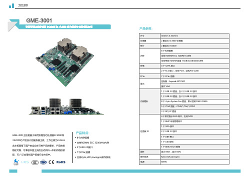
产品特点:
◆ 8个内存插槽 ◆ 支持RDIMM ECC 3200MHz内存 ◆ 2个USB 3.0接口 ◆ 7个PCIe 插槽 ◆ 支持in,UOS,Loongnix操作系统
产品参数:
尺寸 处理器 桥片 内存 存储 PCIe 显示
内部插针
后面板 IO
固件 操作系统 电源
304mm X 330mm 2 颗龙芯 3C5000 处理器 2 颗龙芯 7A2000 8 个内存插槽 支持 RDIMM ECC 3200MHz 内存 支持单条 RDIMM 容量 16GB/32GB/64GB 内存 4 个 SATA 接口 2 个 M.2 接口,支持 PCIe,结构尺寸 2280 7 个 PCIe 插槽 控制器:Aspeed AST2500 接口 VGA 1 个 USB 3.0 插座,含 2 个 USB 3.0 接口 1 个 USB 2.0 插座,含 2 个 USB 2.0 接口 8 个 4-pin System Fan 插座,默认控制 FAN3-FAN6 5 个 JTAG 插座:CPU0/1,7A0/1,CPLD 3 个 BP_I2C 插座 4 个带灯指示 RJ45 网口,支持 NCSI 1 个 BMC 专用管理网口 1 个 VGA 接口 2 个 USB 3.0 接口 1 个 DB9 串口 1 个 UID 按钮 1 个 BMC Reset 按钮 昆仑 BIOS,昆仑 BMC Kylin,UOS,Loongnix 800W
工控主板
GME-3001
采用双路龙芯处理器 3C5000 和 7A2000 芯片组设计的服务器主板
GME-3001主板是基于采用双路龙芯处理器3C5000和 7A2000芯片组设计的服务器主板,工作主频为2.2GHz 此主板具备了国产安全自主可控产品的要求,产品性能 稳定可靠,可兼容市面主流的台式机和一体机机箱的装 配,可 广泛应用在国产领域行业市场中。
Schneider Electric 产品数据手册:9070TF300D1 变压器控制 300VA
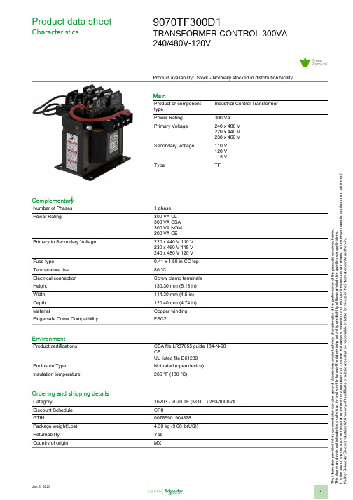
1
The information provided in this documentation contains general descriptions and/or technical characteristics of the performance of the products contained herein. This documentation is not intended as a substitute for and is not to be used for determining suitability or reliability of these products for specific user applications. It is the duty of any such user or integrator to perform the appropriate and complete risk analysis, evaluation and testing of the products with respect to the relevant specific application or use thereof. Neither Schneider Electric Industries SAS nor any of its affiliates or subsidiaries shall be responsible or liable for misuse of the information contained herein.
Jan 6, 2020
9070TF300D1
TRANSFORMER CONTROL 300VA 240/480V-120V
- 1、下载文档前请自行甄别文档内容的完整性,平台不提供额外的编辑、内容补充、找答案等附加服务。
- 2、"仅部分预览"的文档,不可在线预览部分如存在完整性等问题,可反馈申请退款(可完整预览的文档不适用该条件!)。
- 3、如文档侵犯您的权益,请联系客服反馈,我们会尽快为您处理(人工客服工作时间:9:00-18:30)。
CHARACTERISTICS
Maximum Recurrent Peak Reverse Voltage Maximum RMS Voltage Maximum DC Blocking Voltage Maximum Average Forward Rectified Current Peak Forward Surge Current 8.3ms Single Half Sine-Wave Super Imposed on Rated Load(JEDEC Method) Typical Thermal Resistance Typical Junction Capacitance (Note2) Peak Forward Voltage at 15.0A DC Maximum DC Reverse Current at Rated DC Blocking Voltage @TJ=25℃ @TJ=100℃ @TA =75 ℃
SYMBOL VRRM VRMS VDC IO
HER HER HER HER HER HER HER HER 3001PT 3002PT 3003PT 3004PT 3005PT 3006PT 3007PT 3008PT 50 100 200 300 400 600 800 1000 35 50 70 100 140 200 210 300 30 280 400 420 600 560 800 700 1000
REVERSE VOLTAGE - 50 to 1000Volts FORWARD CURRENT - 30.0 Amperes TO-3P
.245(6.2) .820(5.7) .645(16.4) .625(15.9) .085(2.16) .075(1.90) .135(3.4) .115(2.9) .203(5.16) .193(4.90)
TJ=25°C 1.0
0.1 20 40 60 80 100 120 140
PERCENT OF RATED PEAK REVERSE VOLTAGE(%)
FIG.4-TYPICAL INSTANTAEOUS FORWARD CHARACTERISTICS 80 0 40 20 10 4 2 1.0 0.4 0.2 0.1 0.5 0.7 0.9 1.1 1.3 1.5 1.7 1.9 0.1 0.5 1 2 5 10 20 50 100 1000 REVERSE VOLTAGE,(V)
.093(2.30) .076(1.97) .858(21.8) .820(20.8)
MECHANICAL DATA
●Case: TO-3P molded plastic ●Epoxy: UL94V-0 rate flame retadant ●Lead: MIL-STD-202E method 208C guaranteed ●Mounting position :Any ●Weight:5.1grams ●polarity:As marked
SINGLE PHASE HALF WAVE 60HZ RESISTIVE OR INDUCTIVE LOAD
FIG.2-TYPICAL REVERSE CHARACTERISTICS
TJ=100°C
100
0
50
100
150
AMBIE.3-MAXIMUM NON-REPETITVE FORWARD SURGE CURRENT PEAK FORWARD SURGE CURRENT,(A) 600 500 400 300 200 100 0 1 2 10 20 5 5 NUMBER OF CYCLES AT 60HZ 50 100 8.3 ms Single Half-Sine-Wave (JEDEC METOD)
HER3001PT thru HER3008PT
HIGH EFFICIENCY GLASS PASSIVATED RECTIFIERS FEATURES
●Low power lose;high efficiency ●Low forward voltage drop ●Low thermal resistance ●High current capability ●High speed switching ●High surge capacity ●High reliability
.160(4.1) .140(3.5) .795(20.2) .775(19.7)
.095(2.4) .085(2.1) .127(3.22) .117(2.97) .086(2.18) .076(1.93) .030(0.76) .020(0.51) .048(1.22) .044(1.12)
.225(5.7) .205(5.2)
T J=25°C PULSE WIDTH 300uS 1% DUTY CYCLE HER3006PT - HER3008PT
FIG.5-TYPICAL JUNCTION CAPACITANCE
HER3001PT HER3003PT
INSTANTANEOUS FORWARD CURRENT,(A)
300 JUNCTION CAPACITANCE(pF) 250 200 150 100 50
Dimensions in inches and (millimeters)
MAXIMUM RATINGS AND ELECTRICAL CHARACTERISTICS
Rating at 25℃ ambient temperature unless otherwise specified. Single phase, half wave ,60Hz, resistive or inductive load. For capacitive load, derate current by 20%
T J=25°C
HER3004PT HER3005PT
INSTANTANEOUS FORWARD VOLTAGE, (V)
~ 135 ~
�
2.Measured at 1.0 MHZ and applied reverse voltage of 4.0VDC.
~ 134 ~
RATING AND CHARACTERTIC CURVES HER3001PT thru HER3008PT
FIG.1- TYPICAL FORWARD CURRENT DERATING CURVE AVERAGE FORWARD CURRENT,(A) 36 1000 30 24 12 6 0 INSTANTANEOUS REVERSE CURRENT(uA)
UNIT V V V A
IFSM RθJA CJ VF IR TRR TJ,TSTG 1.0
400 1.0 125 1.3 10 150 60 -55 to + 150 1.7
A ℃/W pF V μA nS ℃
Maximum Reverse Recovery Time(Note1) Operating and Storage Temperature Range NOTES:1.Measured with IF=0.5A,IR=1A,IRR=0.25A
