Presentation_SINAUT_GPRS_Training-Part2
MOTOROLA基站初级培训11

目录MOTOROLA基站初级培训内容:●设备和基本操作(详见已发资料)●常用BTS命令●告警●BTS常见故障及问题处理●空中接口●数据库附录:●连线表●常用缩写时间仓促,有不妥之处,请多包涵常用BTS命令:命令的安全等级BSS 命令根据对系统的影响程度分为三个等级,访问不同的等级需要不同的password。
Level 1、该等级命令可以显示系统参数。
Level 2、在该等级,可以使用所有系统命令,包括更改系统database。
操作者可以更改Level1、Level2的password。
Level 3、该等级除了具有Level2的功能之外,还可以使用executive monitor(emon)。
到此等级需要通过两层password(3stooges,4beatles)。
假如购买了软件Feature,可以更改Level3的password。
●disp_cell <cell_desc>:显示小区有关参数●add_neighbor <src_gsm_cell_id><neighbor_gsm_cell_id> <placement>:添加邻小区<placement>internal 欲添加的neighbour cell 在本BSS中external 欲添加的neighbour cell在本BSS外●disp_neighbor <src_cell_desc>:显示某小区的邻小区●del_neighbor <src_cell_desc|all> <neighbor_cell_desc|all>:删除邻小区●disp_cell_status <location>:显示特定小区或某个站所有小区的状态。
可以看到小区工作状态,SDCCH、TCH的配置和占用情况●disp_bss:显示BSS下所有基站小区的信息●disp_gsm_cells <location>:显示某个site的所有小区信息●disp_rtf_channel <location> <rtf_id1> <rtf_id2> [<timeslot_number>]:显示载频空中接口信道状态,查看TCH、SDCCH等占用情况●disp_mms_ts_usage <location> <mms_id1> <mms_id2>:显示MMS上所有时隙的状态●equip <location> <dev/func_name>:在CM数据库中配置器件或功能●ins_device <location> <dev_name> <id1> <id2>:将器件恢复到工作状态●Lock_device <location> <dev_name> <id1> <id2>:锁定某个器件●unlock_device <location> <dev_name> <id1> <id2>:解锁某个器件●reset_device <location> <dev_name> <id1> <id2>:复位某个器件●reset_site [<location>]:复位基站●disp_act_alarm<location>[<device_name> <dev_id1> <dev_id2>:显示告警●chg_level:改变安全等级缺省的level 2的password 为3stooges缺省的level 3的password 为4beatles●disp_equipment <location> [<dev/func_name> <id1> <id2>:显示器件或功能的配置情况●disp_site:显示当前站号●disp_version:显示软件版本●reattempt_pl <location> <gclk_id1>:时钟重锁●state <location> <dev/func_name> <dev/func_id1> <dev/func_id2>:显示基站器件或功能状态●help [<command>]:显示某个命令的帮助信息参数解释若不输入<command>,则显示在当前security level 下允许使用的所有命令,否则显示有关指定的<command>的帮助信息●man <command>:显示某个命令详细用法●history [<num_commands>]:显示先前输入的命令参数解释若没有输入<num_commands>,系统将形式先前输入的最后23个命令●!!:输入刚才最后一条命令●!s:表示输入刚才最后一条已s字母开头的命令,诸如:!d、!ins等告警:告警严重级别表明此故障发生对系统的影响程度。
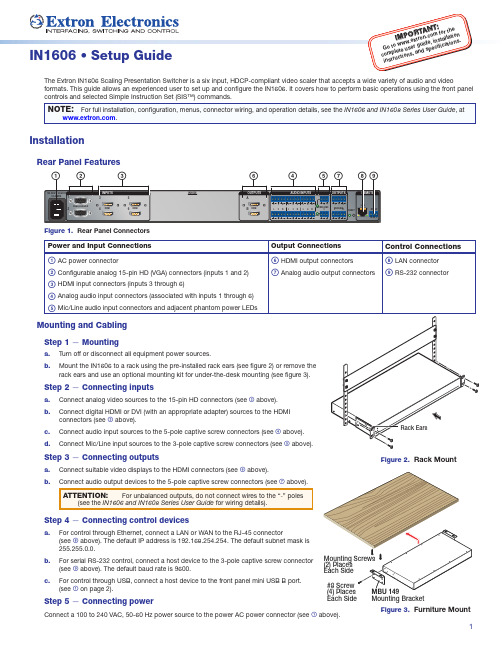
Extron IN1606 Scaling Presentation Switcher 安装指南说明

1I M t ow w w .e x t r o n r g u i d e , i n s t al l a f ic a t i o n s .Step 3 — Connecting outputsa.Connect suitable video displays to the HDMI connectors (see f above).b. Step 4 — Connecting control devicesa.For control through Ethernet, connect a LAN or WAN to the RJ-45 connector(see h above). The default IP address is 192.168.254.254. The default subnet mask is 255.255.0.0.b. For serial RS-232 control, connect a host device to the 3-pole captive screw connector(see i above). The default baud rate is 9600.c.For control through USB, connect a host device to the front panel mini USB B port. (see a on page 2).Step 5 — Connecting powerConnect a 100 to 240 VAC, 50-60 Hz power source to the power AC power connector (see a above).Figure 2. Rack MountFigure 3. Furniture MountEach SideMounting Bracket2IN1606 • Setup Guide (Continued)Front Panel OverviewFigure 4. Front Panel Featuresa Front panel config port — Connect a host device to the mini USB B port for device configuration, control, and firmware upgrades.b Input selection buttons (1-6) — Press one of these buttons to select an input. The buttons light amber for audio and video, green for videoonly, or red for audio only.c Status LED indicators —Input Signal LEDs — Light for the corresponding input when active video content is detected on that input.Output Signal LEDs — Remain lit green when active video is being output, or blink amber when output video and sync are disabled.Input HDCP LEDs — Light for each input signal that is HDCP-encrypted. Analog inputs 1 and 2 cannot be HDCP-encrypted.Output HDCP LEDs — Light for an output when it is currently HDCP-encrypted.d Menu and Enter buttons — Press these buttons to access and navigate the on-screen display (OSD) menu system.e Navigation buttons — Press these buttons to navigate through the on-screen display menu system or change selected settings.f Volume knob and LED indicators — Rotate the Volume knob to adjust the variable analog audio output (default), mic, or program volume(see the IN1606 and IN1608 Series User Guide to configure the knob through group masters). The eight Volume LED indicators light in order according to the audio volume level. The bottom LED blinks when the volume is muted. They light in order from bottom to top to indicate a 12.5% increase or decrease in volume (12.5 dB) from 1% (-99 dB) to 99% (-1 dB). The top LED blinks when the volume is 100% (0 dB).Setting Front Panel Lockout Modes (Executive Modes)The IN1606 has two modes of front panel security lock that limit the operation of the device from the front panel.• Executive mode 0 — The front panel is fully unlocked. This is the default setting.• Executive mode 1 — The front panel is completely locked. This can only be enabled or disabled using SIS commands or the internal web pages (see the IN1606 and IN1608 Series User Guide for web page details or the rear page of this guide for the SIS command).•Executive mode 2 — The front panel is locked except for input switching and volume control. Press and hold the Menu and Enter buttons simultaneously for 3 seconds to enable or disable this mode.Configuring the IN1606The IN1606 can be configured through front panel controls and the OSD menu, the internal web pages, the Extron Product Configuration Software, or SIS commands. To access the internal web pages or send SIS commands, connect a host device to the IN1606 via RS-232, USB, or Ethernet connection (the internal web pages can only be accessed through an Ethernet connection).On-Screen Display (OSD) Menu SystemThe IN1606 has an OSD menu consisting of nine submenus that can be accessed using the front panel Menu or Enter button. View the menu on a display connected to either HDMI output connector (see f on page 1). The submenus are:Quick Setup User Presets Picture Controls Input OutputAudioAdvancedCommunicationDevice IntoTo use any submenu:1. Press the Menu or Enter button to access the main menu.2. Press the Up or Down arrow button to navigate to the desired submenu.3. Press the Enter or Right arrow button to access submenu items for the selected submenu.4. Press the Up or Down arrow button to navigate submenu items.5. Press the Enter or Right arrow button to adjust a submenu item.Using the OSD menu to configure the IN1606• Use the Quick Setup submenu to perform an Auto-Image™ the current input, set video input format, input EDID settings, set output resolution, mute audio, activate video test patterns, enable or disable DHCP , and set the IP address.• Use the User Preset submenu to save picture control settings to each input for later manual recall.• Use the Picture Controls submenu to adjust the image position and size, brightness and contrast, color and tint, and detail as needed.•Use the Input submenu to perform an Auto-Image on the current input, set the video input format and film mode, set horizontal and vertical start values, set the number of active horizontal pixels and vertical lines, set the total pixels and phase, set HDCP authorization, and set the EDID for the current input.• Use the Output submenu to set output resolution, HDMI output format for each output, and HDCP notification.3•Use the Audio submenu to mute audio, set the audioinput format for the selected input, set analog audio gain,set mic/line gain and phantom power, adjust mic/line andprogram volume, and set audio output format.•Use the Advanced submenu to select a test pattern,set the screen saver, turn on or off Auto-Image, set the aspect ratio and auto memory settings, adjust the overscan settings, and reset the device to factory defaults.•Use the Communication submenu to view remote port baud rate, the device MAC address, DHCP status, the current IP address and subnet mask, and gateway.NOTE:Press and hold the Enter button for 10 seconds to edit settings in the Communication submenu.•Use the Device Info submenu to view the devicename, firmware build, temperature, input and output information, and detected displays. This tab is read-only.Internal Web PagesThe IN1606 can be configured, controlled, and operatedthrough the Ethernet port when connected to a LAN or WAN, using a web browser. The browser displays thefactory-installed web pages, which provide a means of configuring and operating the device. Enter the IP address of the unit in the browser Address field to access the web pages (see the IN1606 and IN1608 Series User Guide for more details). The default IP address is 192.168.254.254. The default subnet mask is 255.255.0.0.Product Configuration SoftwareTo configure the IN1606 using the Product ConfigurationSoftware, install the software (available on the Extron website, ) to a PC connected to the IN1606 via Ethernet, RS-232, or front panel USB Config port. After the installation, start the program. For full instructions, press <F1> or click the ? button and select Help File .Firmware UpgradesThe onboard firmware of the IN1606 can be upgraded via the internal web pages or the Extron Firmware Loader program (available on the Extron website, ).Output RatesOutput rates can be set using the OSD menu, the internal web pages, PCS, or SIS commands. The table below displays the most commonly used resolutions and refresh rates and the corresponding SIS values. The command to set the output rate is EX5$RATE }, where X5$ is the SIS value for the resolution and refresh rate combination as given in the example table below (see the IN1606 and IN1608 Series User Guide for the full list).SIS Variable X5$ for EDID or Output Resolution and Refresh Rate Combination (Where X5$ = 10 through 92)Resolution 23.98 Hz24 Hz25 Hz29.97 Hz30 Hz50 Hz 59.94 Hz60 Hz 75 Hz 1024x7681920211280x8003132331440x9005253541680x105059601920x12006364720p 686970717273*1080p 7778798081828384* = defaultBasic SIS Command TableThe IN1606 can be configured with specific SIS commands via an RS-232, USB, or Ethernet connection. Use the Extron DataViewer utility or a control system to send and receive SIS commands. The table on the next page lists a selection of SIS commands. For a full list of SIS commands and variables, see the IN1606 and IN1608 Series User Guide , at .Audio InputFormatDetailsNone Mutes all audio for selected input. Sets “No Audio” EDID.Analog Sets the selected input to analog (default for inputs 1 and 2). Sets “No Audio” EDID.LPCM-2Ch Sets the selected input to LPCM-2Ch digital audio (default for inputs 3-6). Sets 2Ch audio EDID.Multi-Ch Sets the selected input to Multi-Ch digital audio. Sets Multi-Ch audio EDID.LPCM-2Ch autoSets the selected input to prioritize digital audio. Analog audio is passed when digital audio is not present. Sets 2Ch audio EDID.Multi-Ch autoSets the selected input to prioritize digital audio. Analog audio is passed when digital audio is not present. Sets Multi-Ch audio EDID.468-2290-50Rev. B 06 13Extron USA Headquarters+1.800.633.9876 (Inside USA/Canada Only)Extron USA - West: +1.714.491.1500 FAX: +1.714.491.1517Extron USA - East: +1.919.850.1000FAX: +1.919.850.1001© 2013 Extron Electronics — All rights reserved. All trademarks mentioned are the property of their respective owners. 。
联通GPRS网管培训

gsh disconnect_fr_frac -eq {Magazine Slot 1 1 } -trunk E1T1Trunk frac Fraction 4) 拆除E1T1 fraction gsh delete_e1t1_frac -eq {Magazine Slot 1 1} -trunk E1T1Trunk -frac Fraction 5) 拆除NSE gsh delete_nse -nse Nsei 6) 拆除BSC gsh delete_bsc -bsc BscName
trunk Timeslot
Broad band (SS7 over ATM) • Card type: IBAX • Link Id: Eqpos
VPI ATM PVC
VCI
ATM
Rev PA1
2021/7/12 20
CBC/YOF/JS Liang Yongzhong
➢ MTPL-3
LinkSet Tabel LinkSet1
Rev PA1
2021/7/12 15
CBC/YOF/JS Liang Yongzhong
➢ 创建NTBSC72 Gb脚本 (ntbsc72.add)
#!/usr/bin/sh
NTBSC72,15,1501,2,3,6,1,1-8
GSH=/usr/bin/gsh
1502,2,6,3,1,1-8
$GSH create_bsc NTBSC72
•Link1 •Link2 LinkSet2 •Link3 •Link4
LinkSet1
RoutSetC AltRout1
NodeA
RoutSet Tabel RoutSetC
OVATION操作员培训htc

Ovation 操作员站. . .课程目标
*
美国西屋 OVATION 控制系统培训…第一讲---操作员站
*
Ovation 操作员站. . . 功能
操作员事件
过程画面
趋势图
报警信息
点信息细目
点信息一览
美国西屋 OVATION 控制系统培训…第一讲---操作员站
美国西屋 OVATION 控制系统培训…第一讲
*
使用菜单系统 使用Point menu 使用打印选项窗口 使用点信息系统 使用基本报警系统 使用过程画面系统 使用趋势系统 显示系统状态图 使用Put Highway Online操作 使用点浏览功能 使用日志记录功能 浏览General Message窗
*
美国西屋 OVATION 控制系统培训…第一讲操作员站---菜单系统
*
美国西屋 OVATION 控制系统培训…第一讲操作员站---菜单系统
*
美国西屋 OVATION 控制系统培训…第一讲操作员站---菜单系统
*
美国西屋 OVATION 控制系统培训…第一讲操作员站---菜单系统
*
美国西屋 OVATION 控制系统培训…第一讲操作员站---菜单系统
操作员站 过程图形显示 全面的控制和报警 操作事件记录 点信息及趋势
计算服务器 性能计算 特殊应用
美国西屋 OVATION 控制系统培训…第一讲
*
Ovation 网络 . . . 连接统一的企业化管理
开放式数据基本连接 (ODBC) 动态数据交换 目标链接及嵌入 (OLE) 结构查询语言 (SQL) X-Window Java 程序服务器 过程控制(OPC)的目标链接与嵌入 - 未来的
全业务培训P PT(实验)-6-语音业务

IMS语音故障实验操作
实验案例:某新开GPON语音用户,号码无法主被叫 判断可能的原因: 1)号码开户问题 2)ONU数据配置问题 基本处理步骤: 步骤1:查看PBOSS系统号码开开户流程,确认流程无卡单或其他问题。 步骤2:确认ONU在线,登录ONU后测试PING语音网关与SBC地址(120.193.1.4或 120.193.1.12)是否能通。 步骤3:查看ONU数据配置,语音vlan是否透传,anid是否正确,用户号码的注册密
MA5620(config)#interface sip 0 MA5620(config-if-sip-0)# sipprofile modify syspara 72 2 MA5620(config-if-sip-0)#reset。
步骤3:登录ONU,查看号码功能权限设置中,呼叫等待功能是否开启
sippstnuser rightflag set 0/2/1 telno 56922283 cw enable
码是否正确 故障处理结果:
用户号码的注册密码输入错误,导致号码无法注册,修改密码后号码注册正常,测试 通话正常。
IMS语音故障实验操作
实验案例:某新开GPON语音无法进行呼叫转移;在通话时,第三方拨入听正常振铃 判断可能的原因: 1)号码权限问题 2)ONU数据配置问题 基本处理步骤: 步骤1:查看系统中号码权限设置,确认呼转功能是否开启。 步骤2:登录ONU,进入sip接口模式,查看设备72控制点设置是否正确,否则增加 72控制点,并重启sip接口
全业务实战能力提升培训 之实验案例
2013.4
ห้องสมุดไป่ตู้
目录
1 2 3 4
互联网实验题目 电路出租与VPN实验题目 互联网优化实验题目 GPRS、SP实验题目
@GPRS_planning_Radio

MSC
Gr
HLR
Parameter Coverage PlanningAir InterfacePlanning Planning
BTS
BSC
Gs
Gb
SGSN
Gn Gp
GPRS Core Network
IP Backbone
Gn
GGSN
Other operator's GPRS network
Interworking News in BSS S10
GPRS OverviewNokia GPRS
Solution
Parameter Coverage PlanningAir InterfacePlanning Planning
GSM + GPRS
MSC ISP GGSN
Internet
PSTN Server
PS Common Channels
CS Common Channels
PBCCH BCCH CCCH PPCH PCH AGCH RACH PAGCH PRACH PCCCH
Logical Channels (2)
Interworking News in BSS S10
GPRS OverviewNokia GPRS
Server
Circuit-switching
• End User Perception Coverage Service Probability Call Set-up Time Call Set-up Success Rate (CSSR) Call Completion Rate (CCR) Overall Call Success Rate (OCSR) Call Quality (BER)
GPRS业务测试

GPRS业务测试课程目的学习完本课程,你将能够:•熟悉GPRS业务测试内容•掌握GPRS业务测试方法目录GPRS业务测试的影响因素GPRS业务测试项目介绍GPRS业务测试工具介绍GPRS业务测试中常见问题总结影响测试指标的外在原因GPRS业务测试的影响因素GPRS业务测试准备GPRS业务测试的影响因素目录GPRS业务测试的影响因素GPRS业务测试项目介绍GPRS业务测试工具介绍GPRS业务测试中常见问题总结q测试时间视客户要求而定,通常安排在周一至周五9:00-19:00进行q地点选择原则¦在城市中选20-40个测试点。
具体测试点分布要求:火车站、机场、三星级以上酒店、大型商场休闲区、大学学校、大型居民区、商务场所、旅游景区¦测试点按照地理、话务因素综合考虑均匀分布,突出重点区域¦在测试前测量当前位置的无线信号,检查信号强度,确保在该点有GPRS覆盖,避免在测试过程中频繁小区重选q适用环境:m市区主要道路和重要高速、铁路干线q测试时间:m视客户要求而定,通常安排在周一至周五9:00-19:00进行q测试速度:m在市区保持正常行驶速度,一般车速在30-35公里/小时,在高速公路上车速一般不应低于70公里q测试路线:m要求均匀覆盖市区主要街道,并且尽量不重复;环城高速、高架桥、市区到机场公路必须进行测试q测试时长:m根据城市的规模来定,也可以根据用户的要求确定每个城市的测试时长。
三方测试时省会城市18个忙时,地级城市12个忙时测试项目超时定义GPRS业务测试项目介绍目录GPRS业务测试的影响因素GPRS业务测试项目介绍GPRS业务测试工具介绍GPRS业务测试中常见问题总结CDS 路测工具的安装步骤u 测试电脑重装系统及系统设置1u 测试软件及相应驱动的安装2u 调制解调器的安装3u 拨号连接的建立4u 测试软件的配置5u 工作平台以及测试脚本的配置6GPRS 业务测试工具介绍CDS路测软件用户界面GPRS业务测试工具介绍CDS路测软件装载说明第一集第二集第三集GPRS 业务测试工具介绍目录GPRS业务测试的影响因素GPRS业务测试项目介绍GPRS业务测试工具介绍GPRS业务测试中常见问题总结。
使用TEMS设备进行GPRS测试指导书

2004-12-29 华为机密,未经许可不得扩散第i 页, 共18页资料编码产品名称 使用对象网络规划优化工程师 产品版本 编写部门 无线网络规划部资料版本使用TEMS设备进行GPRS测试指导书拟 制:崔耀文 日 期: 2004-11-20 审 核:日 期: 审 核:日 期: 批 准:日 期:华 为 技 术 有 限 公 司版权所有 侵权必究2004-12-29 华为机密,未经许可不得扩散第ii 页, 共18页修订记录 日期 修订版本 描述作者 2004-12-04 1.0 初稿完成崔耀文目录第1章工具简介 (1)第2章软件的安装以及设备的连接 (1)第3章 GPRS测试 (2)3.1 CQT测试 (2)3.1.1 测试时间 (2)3.1.2 测试选点 (2)3.1.3 CQT测试内容、测试记录项目及测试步骤 (2)3.1.4 小结 (6)3.2 DT测试 (6)3.2.1 测试时间 (6)3.2.2 测试路线 (6)3.2.3 测试内容与方法 (6)3.2.4 指标统计 (7)3.3 TEMS软件锁频功能 (8)3.4 统计 (9)3.4.1 CQT统计 (9)3.4.2 统计DT的各种测试结果。
(12)3.5 GPRS测试中易出现的问题和需要注意的地方 (12)关键词:GPRS、TEMS、路测、CQT、DT、网络优化摘要:本文是对使用TEMS进行GPRS测试的文档。
文中对中国移动集团公司2004年GPRS测试规范中DT 和CQT的各项指标进行了说明以及使用TEMS对这些指标进行测试进行了阐述。
通过对这些测试指标及TEMS使用方法的阐述,使我们更清楚地了解了TEMS软件的功能,为今后我们进行网络优化时使用这个软件来改善网络性能提供了有效的借鉴信息。
缩略语清单:GPRS 通用分组无线业务TBF 临时块流APN 接入点名称PDP 分组数据协议参考资料清单:《TEMS操作指导书》《TEMS操作指导书附件》第1章工具简介Tems Investigation 是一个全面的强数据测试和空中接口测试相结合的车载测试解决方案。
移动通信课程设计报告-GPRS模块用AT指令被叫通话

课程设计报告课题名称 _____移动通信课程设计____ 学院电子信息学院专业通信工程班级 BX0906学号姓名指导教师朱一群定稿日期: 2012年 06月15日目录一、课程设计题目 0二、课程设计目的 0三、课程设计时间 0四、课程设计环境 0五、课程设计任务和要求 05.1课程设计任务 05.2课程设计要求 0六、课程设计原理 06.1 GPRS基础知识 06.2 GPRS移动终端的分类 (1)6.3 GPRS的应用 (2)6.4 GPRS MODEM调试工具V1.0使用说明 (2)6.5 GPRS无线通信模块 (2)6.6 AT指令 (3)6.7 GPRS模块有关电话控制的AT指令 (4)七、课程设计过程及调试、结果 (4)7.1 硬件连接 (4)7.2 串口测试 (5)7.3 GPRS被叫处理 (5)八、课程设计体会 (6)参考文献 (6)答辩记录 (7)一、课程设计题目GPRS模块用AT指令被叫通话二、课程设计目的1.通过该课程设计,使学生对移动通信的基本概念、基本原理和基本技术有较全面的了解和领会;2.通过该课程设计,能应用移动通信的原理和技术分析、诠释和解决移动通信过程中出现的问题,并能设计一些简单的移动通信系统,3.通过该课程设计,加深对移动通信课程理论的理解,为将来从事移动通信技术的技术管理、维护、设计和研究奠定必要的理论基础和实际技能。
三、课程设计时间1周(四、课程设计环境1. GPRS MODEM调试工具V1.02. 8A实验箱GPRS模块3.CPU4.电话、手机、SIM卡五、课程设计任务和要求5.1课程设计任务GPRS无线通信模块(又称为GPRS MODEM或GPRS模块)的基本知识,了解AT指令基本知识,掌握GSM/GPRS无线通信模块的使用,通过对GPRS模块输入AT指令实现GPRS模块的被叫通话。
5.2课程设计要求通过课程设计,熟悉GPRS模块的AT指令,简述GSM/GPRS模块调试工具的AT指令操作方法;简述GPRS模块的被叫过程。
GPRS系列模组用户手册说明书

GPRS系列模组用户手册版本1.7Ai-Thinker IncCopyright(c)2019免责申明和版权公告本文中的信息,包括供参考的URL地址,如有变更,恕不另行通知。
文档"按现状"提供,不负任何担保责任,包括对适销性、适用于特定用途或非侵权性的任何担保,和任何提案、规格或样品在他处提到的任何担保。
本文档不负任何责任,包括使用本文档内信息产生的侵犯任何专利权行为的责任。
本文档在此未以禁止反言或其他方式授予任何知识产权使用许可,不管是明示许可还是暗示许可。
文中提到的所有商标名称、商标和注册商标均属其各自所有者的财产,特此声明。
注意由于产品版本升级或其他原因,本于册内容有可能变更。
深圳市安信可科技有限公司保留在没有任何通知或者提示的情况下对本于册的内容进行修改的权利。
本于册仅作为使用指导,深圳市安信可科技有限公司尽全力在本于册中提供准确的信息,但是深圳市安信可科技有限公司并不确保于册内容完全没有错误,本于册中的所有陈述、信息和建议也不构成任何明示或暗示的担保。
版本记录2017.12.08V1.5LVX 1.增加附件一2.增加对于串口的描述3.增加了对GPS\GPRS指示灯的说明2017.12.11V1.6LVX 修正了A9/A9G按键复位电路的复位说明(附件二)2019.12.27V1.7XYJ 修改了电源电压,删去了A6的内容,更新了docs链接目录1产品概述 (1)1.1产品特性 (1)1.2应用方案 (1)2模组接口 (2)2.1尺寸封装 (2)2.1管脚定义 (4)3电气特性 (8)3.1极限参数 (8)3.2建议工作环境 (8)3.3数字端口特征 (8)3.4功耗 (9)3.5发射功率 (10)3.6接收灵敏度 (10)4硬件指导 (11)4.1电源设计 (11)4.2开关电路设计 (12)4.3SIM卡设计 (13)4.4ADC参考设计 (14)4.5SPEAKER参考设计 (14)4.6MIC参考设计 (15)4.7天线设计 (15)5使用指南 (16)5.1基础AT指令介绍 (16)5.1.1AT (16)5.1.2AT+GMR (16)5.1.3AT+RST=1 (16)5.1.4AT+CCID (17)5.1.5AT+CSQ (17)5.2使用示例 (18)更多使用示例 (21)附件 (22)附件一补充 (22)附件二A9/A9G复位电路时序图及说明 (22)6附录 (24)7联系我们 (24)hnology Co.,Ltd All Rights 第1页共21页1产品概述GPRS系列模块是安信可科技最新推出的一系列简单、易用的GPRS数据传输模块,提供串口转GPRS/短信息/语音通话等信息传输功能,被广泛应用于物联网/车载/电力环境检测等领域。
Presentations_3GPP-LTE

12
3GPP LTE presentation • Physical Layer (Continued)
– The channel coding scheme for transport blocks in LTE is Turbo Coding with a coding rate of R=1/3, two 8-state constituent encoders and a contention-free quadratic permutation polynomial (QPP) turbo code internal interleaver. Trellis termination is used for the turbo coding. Before the turbo coding, transport blocks are segmented into byte aligned segments with a maximum information block size of 6144 bits. Error detection is supported by the use of 24 bit CRC. – Coexistence scenarios have been already done for the downlink and result can be found in TR 36.942
11
3GPP LTE presentation
• Physical Layer details (continued)
– The physical channels defined in the downlink are the Physical Downlink Shared Channel (PDSCH), the Physical Downlink Control Channel (PDCCH) and the Common Control Physical Channel (CCPCH). The physical channels defined in the uplink are the Physical Uplink Shared Channel (PUSCH) and the Physical Uplink Control Channel (PUCCH). – In addition, signals are defined as reference signals, primary and secondary synchronization signals or random access preambles. – The modulation schemes supported in the downlink are QPSK, 16QAM and 64QAM, and in the uplink QPSK, 16QAM and 64QAM. The Broadcast channel use only QPSK
物联网在智能交通中的应用英文版

在以上研究背景下,咱们提出了现有智能交通系统模式所存在的问题与不足,并探讨了研究物联网环境下智能交通系统模型与架构的意义;第二,通过度析现存问题,论述智能交通系统引入物联网技术的必要性。
After considering the existed problem, we point out the necessity of lead-in the IOT into intelligent transportation.
【Key Words】Intelligent Transportation System;Internetof Things; System Architecture; Evaluation.
Nowadays, the road network of Shenzhen has formed a net pattern with the several decades of building and improving. Because of the increasing urban population, the constitution of ITS has become the only way to sustain the Shenzhen's transportation. The ITS is the orientation of future transportation. It makes the traditional transmutation pattern more intelligent, safe, green and efficient by high technology.
- 1、下载文档前请自行甄别文档内容的完整性,平台不提供额外的编辑、内容补充、找答案等附加服务。
- 2、"仅部分预览"的文档,不可在线预览部分如存在完整性等问题,可反馈申请退款(可完整预览的文档不适用该条件!)。
- 3、如文档侵犯您的权益,请联系客服反馈,我们会尽快为您处理(人工客服工作时间:9:00-18:30)。
Service & Support
Automation task Platform Application Service Demo system
S
Platform – Establishing a connection
MD 720-3
6
Automation and Drives
Knowledge Management
Micro Automation Set 21 - Workshop
Service & Support
Automation task Platform Application Service Demo system
3
Automation and Drives
Knowledge Management
Micro Automation Set 21 - Workshop
Service & Support
Automation task Platform Application Service Demo system URL Static IP address
Platform – S7 block WDC_INIT
Knowledge Management – Micro Automation Set 21 Workshop – 03.02.2006 – Michael Fiedler
9
Automation and Drives
Knowledge Management
1 S 2 S 3 S 4 Q C Q C Q C
S Q C
Verification of all SIM card parameters (e.g. PIN) Establishing a connection to the GSM PROVIDER Successfully established connection to the GSM PROVIDER Establishing a connection to the SINAUT MICRO SC server Successfully established connection to the SINAUT MICRO SC server
5
Automation and Drives
Knowledge Management
Micro Automation Set 21 - Workshop
Service & Support
Automation task Platform Application Service Demo system
2
Automation and Drives
Knowledge Management
Micro Automation Set 21 - Workshop
Service & Support
Automation task Platform Application Service Demo system
Knowledge Management
Micro Automation Set 21 - Workshop
Service & Support
Automation task Platform Application Service Demo system //Server IP Adress INIT_IP_Server "217.91.50.138" //Destination Port INIT_Destination_Port "26863" //Modem Name INIT_Modem_Name "modem8" //Modem Password INIT_Modem_Password "geheim" //SIM PIN INIT_SIM_PIN "9626" //GPRS APN INIT_GPRS_APN "internet" //GPRS APN User INIT_GPRS_APN_USER "guest" //GPRS APN User Password INIT_GPRS_APN_PW "guest" //DNS INIT_DNS "62.134.11.4;195.182.110.132" //
10
Data volume 2 KByte
S 5 S
Q Q
C C
Knowledge Management – Micro Automation Set 21 Workshop – 03.02.2006 – Michael Fiedler
Automation and Drives
Knowledge Management
7
Automation and Drives
Knowledge Management
Micro Automation Set 21 - Workshop
Service & Support
Automation task Platform Application Service Demo system
Data volume
1
53 Byte (Information) 45 Byte (Confirmation)
2
55 Byte + OPC Variable 1 (Information) 45 Byte (Confirmation) ... 55 Byte + OPC Variable n (Information) 45 Byte (Confirmation)
Platform – SINAUT MICRne server port
XML m2mopc.xml
Knowledge Management – Micro Automation Set 21 Workshop – 03.02.2006 – Michael Fiedler
Platform – SINAUT MICRO SC 1
Status monitoring deactivated
S7-200 MD 720-3
S
S QC
PPI
RS232
Live telegram Each 20 minutes
S7-200
MD 720-3
S
OPC tags or Real Time Clock
4
Automation and Drives
Knowledge Management
Micro Automation Set 21 - Workshop
Service & Support
Automation task Platform Application Service Demo system
Platform – SINAUT MICRO SC
Real Time Clock
3
Status Monitoring by real time clock
S7-200
MD 720-3
S
S QC
PPI
RS232
Data live telegram Each 15 minutes
No data received for 15 + 2 minutes? Live telegram
Platform – SINAUT MICRO SC
Enter station name Select unique station number Enter password 1 2 3
Knowledge Management – Micro Automation Set 21 Workshop – 03.02.2006 – Michael Fiedler
1
Automation and Drives
Knowledge Management
Micro Automation Set 21 - Workshop
Service & Support
Automation task Platform Application Service Demo system
Platform - Installation of the Remote Station
DC 24V M
Port 0 Port 1
CPU 224XP
S
S Q C
Gender Changer
MD 720-3
1 2 3 4 5 6 7 8 off on
PPI
RS 232
Knowledge Management – Micro Automation Set 21 Workshop – 03.02.2006 – Michael Fiedler
2
Status Monitoring by value update
PPI
S QC
RS232
Data live telegram Each 15 minutes
No data received for 15 + 2 minutes? Live telegram
Knowledge Management – Micro Automation Set 21 Workshop – 03.02.2006 – Michael Fiedler
Micro Automation Set 21 - Workshop
Service & Support
Automation task Platform Application Service Demo system Address of first data byte and length (max 239 Byte) “0”: Sending „1“: Fetching Reference to clock time buffer of S7 200 Monitoring time 15 seconds Destination address
