GTS8205芯片性能及参数介绍
sy8205fcc工作原理

sy8205fcc工作原理
sy8205fcc是一种电源管理芯片,常用于移动设备和电子产品中。
它的工作原理如下:
1.输入电压检测:sy8205fcc通过内部的电压检测电路,监测外部电源输入电压的稳定性和合理范围。
如果输入电压超过或低于设定的阈值,芯片将采取相应的措施,例如关闭输出或采取保护措施,以防止系统受损。
2.电池管理:sy8205fcc还可以与电池连接,监测电池的充电状态和电流。
当电池电量较低或过充时,芯片将根据设定的阈值进行相应的处理,例如启动充电或停止充电,以保证电池的安全和寿命。
3.功率转换:sy8205fcc还具有DC-DC转换功能,可以将输入电压转换为适合目标设备工作的稳定输出电压。
它通过内部的开关电路和功率管理算法,将输入电压调整为所需的输出电压,并保持输出电压的稳定性和效率。
4.温度保护:为了保护芯片和系统的稳定性,sy8205fcc还配备了温度保护功能。
当芯片温度超过设定的阈值时,它将采取措施,例如减小输出功率或停止工作,以避免过热和损坏。
总的来说,sy8205fcc通过监测和管理输入电压、
电池状态和温度等关键参数,提供稳定的电源输出和保护功能,确保设备的正常运行和安全性。
8205a与dw01工作原理

8205a与dw01工作原理8205a和dw01是常用的保护IC,常用于锂电池的保护电路中。
本文将详细介绍8205a和dw01的工作原理和功能。
8205a是一种多功能保护IC,其主要功能是对充放电过流、过压、过温等情况进行保护。
它由一个微控制器单元(MCU)、电池电流检测电路、电流比较器、过压保护开关和温度检测电路等组成。
8205a可根据不同的应用需求进行配置,具有较高的灵活性。
8205a的工作原理如下:当电池的充放电电流超过设定的阈值时,电流检测电路将检测到这一情况,并将信号传递给MCU。
MCU会根据预先设定的参数,判断是否需要进行保护措施。
如果需要保护,MCU将控制过压保护开关打开,切断电池与负载之间的连接,以防止过流、过压等情况的发生。
此外,8205a还通过温度检测电路,实时监测电池的温度情况,并在温度过高时触发保护机制。
与8205a相比,dw01是一种简化的保护IC,其功能主要是对过放电、过压、过流等情况进行保护。
dw01由一个电流检测电路、一组比较器和一个开关控制电路组成。
与8205a相比,dw01的保护功能较为简单,但成本也更低,适用于成本要求较低的应用。
dw01的工作原理如下:当电池的电压超过设定的阈值或电流超过设定的阈值时,电流检测电路会检测到这些情况,并将信号传递给比较器。
比较器会判断是否需要进行保护措施。
如果需要保护,开关控制电路将切断电池与负载之间的连接,以防止过放电、过压、过流等情况的发生。
值得注意的是,8205a和dw01都需要与电池管理系统(BMS)或其他控制电路进行配合使用。
它们并不能直接控制电池充放电过程,而是通过与其他部分的协作,对电池进行保护。
总结起来,8205a和dw01在锂电池保护电路中起着重要的作用。
8205a具有多种保护功能和较高的灵活性,适用于复杂的应用场景。
而dw01则拥有简化的保护功能和较低的成本,适用于成本要求较低的应用。
无论是8205a还是dw01,它们都能有效保护锂电池免受过充、过放、过流等情况的损害,提高电池的安全性和使用寿命。
8205a芯片参数
8205a芯片参数8205A芯片是一种晶体管型功放,也被称为N-MOSFET晶体管,主要用于单声道音频放大器,功率放大器,电源管理电路等。
其主要特点是功率高、响应速度快、降噪性能好、失真率低、可靠性高等,受到广泛的应用和欢迎。
下面介绍8205A芯片的一些关键参数:1. 负载电阻(RL) - 指芯片输出端的最大负载电阻,超过该值会导致芯片过热、失真、甚至损坏。
对于8205A芯片,其典型输出负载电阻(RL)为8欧姆,最大输出功率为4W。
2. 工作电压(Vdss) - 指芯片能够承受的最大电压值,它取决于芯片的工艺和设计。
8205A芯片的最大工作电压(Vdss)为55V,静态电流(Id)最大可达4A。
3. 输入电容(Ciss) - 指芯片输入端的总电容值,它对于信号传输的带宽和响应速度有极大影响。
8205A芯片的总输入电容(Ciss)为620pF,输出电容(Coss)为140pF。
4. 开关时间(t-on、t-off) - 指芯片在转换工作状态时所需的时间,即开关时间。
开关时间越短,工作状态转换越快,芯片响应速度越快。
8205A芯片的开关时间为20ns。
5. 内部电阻(Rds(on)) - 指芯片工作时的内部电阻值,它能直接影响芯片的能耗和热量产生。
8205A芯片的内部电阻(Rds(on))为45mΩ,可以有效降低功耗和热量产生。
6. 线性失真(LD) - 指芯片在采样信号时产生的非线性变形,会导致输出信号变形和失真。
8205A芯片的线性失真(LD)仅为0.02%,可保持良好的音质。
7. 工作温度范围 - 指芯片正常工作的温度范围。
8205A芯片的工作温度范围为-55℃ ~ 150℃,适用于多种恶劣的工作环境。
总的来说,8205A芯片具备高效、稳定、精确的特点,广泛应用于音频功放、汽车音响和其他需要高保真度的电子设备。
在设计和选型时,需要根据所需的输出功率、输入电压、负载电阻等参数,综合考虑选择最合适的芯片。
8205a6工作原理

8205a6工作原理8205a6是一种工作原理独特的技术,它在各个领域都有广泛的应用。
本文将详细介绍8205a6的工作原理以及其在不同领域的应用。
我们来了解8205a6的工作原理。
8205a6是一种基于先进的数字信号处理技术的系统,它能够对输入信号进行高效的处理和分析。
它采用了一种特殊的算法,通过对输入信号进行数学运算和优化,从而得到输出信号。
8205a6的工作原理可以简单描述为以下几个步骤:首先,它会对输入信号进行采样,将连续的模拟信号转换为离散的数字信号。
然后,通过一系列的数学运算和滤波处理,对数字信号进行分析和处理。
最后,通过输出端口将处理后的信号传输给下游设备或系统。
8205a6的工作原理使得它在许多领域都有广泛的应用。
首先,在通信领域,8205a6可以用于信号处理和调制解调等方面。
它能够提供高质量的信号处理和调制解调功能,从而提高通信系统的性能和可靠性。
在图像和音频处理领域,8205a6也发挥着重要作用。
它可以对图像和音频信号进行高效的处理和优化,从而提供更清晰、更真实的图像和音频效果。
在数字电视、音频设备和摄像机等领域,8205a6的应用非常广泛。
8205a6还可以应用于工业自动化和控制系统。
它可以对传感器信号进行处理和分析,从而实现对工业过程的监控和控制。
在工厂自动化、机器人技术和智能交通系统等领域,8205a6的应用可以提高生产效率和系统性能。
在医学领域,8205a6也有重要的应用价值。
它可以对医学图像和信号进行处理和分析,从而提供医学诊断和治疗的支持。
在医学影像设备、生物信号监测和医疗器械等方面,8205a6的应用可以提高医疗技术的水平和质量。
8205a6是一种工作原理独特的技术,它通过先进的数字信号处理算法,能够对输入信号进行高效的处理和分析。
它在通信、图像音频处理、工业自动化和医学等领域都有广泛的应用。
随着科技的不断发展,8205a6的应用前景将会更加广阔。
8205a芯片参数
8205a芯片参数8205a芯片是一款集成了高压MOS管、控制电路和功率驱动电路于一体的直流电机驱动芯片。
该芯片能够提供稳定可靠的驱动电流,并具有高效率、高性能和低功耗等优点,广泛应用于各种电机驱动控制领域。
首先,8205a芯片主要参数包括最大工作电压、最大输出电流、内部电阻和最大工作温度等。
其最大工作电压一般为22V,最大输出电流可达到3A,内部电阻一般在0.8欧姆左右,最大工作温度为150摄氏度。
这些参数决定了8205a芯片在实际应用中的工作范围和性能表现。
其次,8205a芯片具有多种保护功能,如欠压关断保护、过流保护、过温保护和短路保护等。
欠压关断保护功能可以防止芯片在低于最小工作电压时损坏;过流保护功能可保护电机驱动电路免受过大的电流损害;过温保护功能可以防止芯片在高温环境下过热而失效;短路保护功能可以防止芯片在电机短路时损坏。
此外,8205a芯片还具有较高的工作频率和响应速度。
由于内部采用了先进的控制电路和驱动电路设计,使得8205a芯片能够实现高达20kHz的调制频率,从而提高了功率转换的效率。
而响应速度方面,8205a芯片的开关速度较快,可以在微秒级的时间内完成开关操作,使得电机驱动能够响应迅速、动作灵敏。
另外,8205a芯片具有较低的静态功耗和漏电流。
在无负载或静止状态下,8205a芯片的功耗非常低,基本可以忽略不计。
此外,其漏电流也非常小,能够有效降低能源的浪费,提高整体系统的能效。
最后,8205a芯片还具有较高的稳定性和可靠性。
由于芯片内部采用了成熟的生产工艺和可靠的器件组件,能够保证芯片在不同环境和工作条件下的稳定性和可靠性。
此外,8205a芯片还经过严格的可靠性测试和质量控制,能够满足工业级别的要求,具有较长的使用寿命和稳定的性能。
综上所述,8205a芯片是一款功能强大、性能优越且具有多项保护功能的直流电机驱动芯片。
其参数设计合理、工作稳定可靠,能够满足各种电机驱动控制的需求。
RT8205ABC介绍

1DS8205A/B/C-03 April 2009Ordering InformationNote :Richtek Green products are :` RoHS compliant and compatible with the current require-ments of IPC/JEDEC J-STD-020.` Suitable for use in SnPb or Pb-free soldering processes.Applicationsz Notebook and Sub-Notebook Computersz3-Cell and 4-Cell Li+ Battery-Powered DevicesHigh-Efficiency, Main Power Supply Controllers for Notebook ComputersGeneral DescriptionThe RT8205A/B/C dual step-down, switch-mode power-supply controller generates logic-supply voltages in battery-powered systems. The RT8205A/B/C includes two pulse-width modulation (PWM) controllers fixed at 5V/3.3V or adjustable from 2V to 5.5V. An alternative LGATE1output LG1_CP can be used for external charge pump (RT8205B). And an optional external charge pump can be monitored through SECFB (RT8205C). This device also features 2 linear regulators providing fixed 5V and 3.3V outputs. The linear regulator each provides up to 70mA output current with automatic linear-regulator bootstrapping to the PWM outputs. The RT8205A/B/C includes on-board power-up sequencing, the power-good output, internal soft-start, and internal soft-discharge output that prevents negative voltages on shutdown.A constant on-time PWM control scheme operates without sense resistor and provides 100ns response to load transients while maintaining a relatively constant switching frequency. The unique ultrasonic mode maintains the switching frequency above 25kHz, which eliminates noise in audio applications. Other features include diode-emulation mode (DEM), which maximizes efficiency in light-load applications, and fixed-frequency PWM mode,which reduces RF interference in sensitive applicationFeaturesz Wide Input Voltage Range 6V to 25VzDual Fixed 5V/3.3V Outputs or Adjustable from 2V to 5.5V, 1.5% Accuracy.zAlternative LGATE1 Output (LG1_CP) acts as Clock for Charge Pump (RT8205B)zSecondary Feedback Input Maintains Charge Pump Voltage (RT8205C).z Fixed 3.3V and 5V LDO Output : 70mA z 2V Reference Voltage ±1% : 50uAzConstant ON-Time Control with 100ns Load Step Responsez Frequency Selectable via TONSEL SettingzR DS(ON) Current Sensing and Programmable Current Limit combined with Enable Controlz Selectable PWM, DEM, or Ultrasonic Mode z Internal Soft-Start and Soft-Discharge z High Efficiency up to 97%z 5mW Quiescent Power Dissipation z Thermal ShutdownzRoHS Compliant and Halogen FreeRT8205A : DefaultB : With LG1_CPC : With SECFBMarking InformationFor marking information, contact our sales representative directly or through a Richtek distributor located in your area, otherwise visit our website for detail.2DS8205A/B/C-03 April 2009 Typical Application CircuitPin Configurations(TOP VIEW)RT8205CWQFN-24L 4x4RT8205B WQFN-24L 4x4RT8205A WQFN-24L 4x4ENTRIP1FB1REF TONSELFB2ENTRIP2L G A T E 2V O U T 2V R E G 3B O O T 2P H A S E 2U G A T E 2NCVREG5GNDSKIPSEL ENVIN U G A T E 1L G A T E 1V O U T 1P G O O D B O O T 1P H A S E 1ENTRIP1FB1REF TONSELFB2ENTRIP2L G A T E 2V O U T 2V R E G 3B O O T 2P H A S E 2U G A T E 2LG1_CP VREG5PGND SKIPSEL EN VIN U G A T E 1L G A T E 1V O U T 1P G O O D B O O T 1P H A S E 1ENTRIP1FB1REF TONSELFB2ENTRIP2L G A T E 2V O U T 2V R E G 3B O O T 2P H A S E 2U G A T E 2SECFB VREG5PGND SKIPSEL ENVIN U G A T E 1L G A T E 1V O U T 1P G O O D B O O T 1P H A S E 1V OUT15VOUT2For Fixed Voltage Regulator3DS8205A/B/C-03 April 20095VV OUT2V OUT24DS8205A/B/C-03 April 2009 For Adjustable Voltage RegulatorVV5DS8205A/B/C-03 April 2009V6DS8205A/B/C-03 April 2009 Function Block DiagramFunction Block DiagramPWM Controller (One Side)7DS8205A/B/C-03 April 2009Functional Pin DescriptionENTRIP1 (Pin 1)Channel 1 enable and Current Limit setting Input. Connect resistor to GND to set the threshold for channel 1synchronous R DS(ON) sense. The GND-PHASE1 current-limit threshold is 1/10th the voltage seen at ENTRIP1 over a 0.5V to 2V range. There is an internal 10uA current source from VREG5 to ENTRIP1. The logic current limit threshold is default to 200mV value if ENTRIP1 is higher than VREG5-1V.FB1 (Pin 2)SMPS1 Feedback Input. Connect FB1 to VREG5 or GND for fixed 5V operation. Or connect FB1 to a resistive voltage-divider from VOUT1 to GND to adjust output from 2V to 5.5V.REF (Pin 3)2V Reference Output. Bypass to GND with a 0.22uF capacitor. REF can source up to 50uA for external loads.Loading REF degrades FBx and output accuracy according to the REF load-regulation error.TONSEL (Pin 4)Frequency Selectable Input for VOUT1/VOUT2respectively.400kHz/500kHz : Connect to VREG5 or VREG3300kHz/375kHz : Connect to REF 200kHz/250kHz : Connect to GND FB2 (Pin 5)SMPS2 Feedback Input. Connect FB2 to VREG5 or GND for fixed 3.3V operation. Or connect FB2 to a resistive voltage-divider from VOUT2 to GND to adjust output from 2V to 5.5V.ENTRIP2 (Pin 6)Channel 2 enable and Current Limit setting Input. Connect resistor to GND to set the threshold for channel 2synchronous R DS(ON) sense. The GND-PHASE2 current-limit threshold is 1/10th the voltage seen at ENTRIP2 over a 0.5V to 2V range. There is an internal 10uA current sourcefrom VREG5 to ENTRIP2. The logic current limit threshold is default to 200mV value if ENTRIP2 is higher than VREG5-1V.VOUT2 (Pin 7)SMPS2 Output Voltage-Sense Input. Connect to the SMPS2 output. VOUT2 is an input to the on-time one-shot circuit. It also serves as the SMPS2 feedback input in fixed-voltage mode.VREG3 (Pin 8)3.3V Linear Regulator Output.BOOT2 (Pin 9)Boost Flying Capacitor Connection for SMPS2. Connect to an external capacitor according to the typical application circuits.UGATE2 (Pin 10)High-Side MOSFET Floating Gate-Driver Output for SMPS2. UGATE2 swings between PHASE2 and BOOT2.PHASE2 (Pin 11)Inductor Connection for SMPS2. PHASE2 is the internal lower supply rail for the UGATE2 high-side gate driver.PHASE2 is also the current-sense input for the SMPS2.LGATE2 (Pin 12)SMPS2 Synchronous-Rectifier Gate-Drive Output.LGATE2 swings between GND and VREG5.EN (Pin 13)Master Enable Input. The REF/VREG5/VREG3 are enabled if it is within logic high level and disable if it is less than the logic low level.SKIPSEL (Pin 14)Operation Mode Selectable Input.Ultrasonic Mode : Connect to VREG5 or VREG3Diode Emulation Mode : Connect to REF PWM Mode : Connect to GND8DS8205A/B/C-03 April 2009 GND [Pin 15 (RT8205A), Exposed Pad (25)]Analog Ground for SMPS controller. The exposed pad must be soldered to a large PCB and connected to GND for maximum power dissipation.PGND (Pin 15) (RT8205B/C)Power Ground for SMPS controller. Connect PGND externally to the underside of the exposed pad.VIN (Pin 16)High Voltage Power Supply Input for 5V/3.3V LDO and Feed-forward ON-Time circuitry.VREG5 (Pin 17)5V Linear Regulator Output.VREG5 is also the supply voltage for the low-side MOSFET driver and analog supply voltage for the device.NC (Pin 18) (RT8205A)No Internal Connection.LG1_CP (Pin 18) (RT8205B)Alternative LGATE1 Output for 14V charge pump.SECFB (Pin 18) (RT8205C)The SECFB is used to monitor the optional external 14V charge pump. Connect a resistive voltage-divider from 14V charge pump output to GND to detect the output. If SECFB drops below the threshold voltage, LGATE1 turns on for 300ns (typ.). This will refresh the external charge pump driven by LGATE1 without over-discharging the output voltage.LGATE1 (Pin 19)SMPS1 Synchronous-Rectifier Gate-Drive Output.LGATE1 swings between GND and VREG5.PHASE1 (Pin 20)Inductor Connection for SMPS1. PHASE1 is the internal lower supply rail for the UGATE1 high-side gate driver.PHASE1 is also the current-sense input for the SMPS1.UGATE1 (Pin 21)High-Side MOSFET Floating Gate-Driver Output for SMPS1. UGATE1 swings between PHASE1 and BOOT1.BOOT1 (Pin 22)Boost Flying Capacitor Connection for SMPS1. Connect to an external capacitor according to the typical application circuits.PGOOD (Pin 23)Power Good Output for channel 1 and channel 2. (Logical AND)VOUT1 (Pin 24)SMPS1 Output Voltage-Sense Input. Connect to the SMPS1 output. VOUT1 is an input to the on-time one-shot circuit. It also serves as the SMPS1 feedback input in fixed-voltage mode.9DS8205A/B/C-03 April 2009Recommended Operating Conditions (Note 3)z Input Voltage, V IN ------------------------------------------------------------------------------------------------------6V to 25Vz Junction T emperature Range ----------------------------------------------------------------------------------------−40°C to 125°C zAmbient T emperature Range ----------------------------------------------------------------------------------------−40°C to 85°CAbsolute Maximum Ratings (Note 1)zVIN, EN to GND -----------------------------------------------------------------------------------------------–0.3V to 28V z BOOTx to GND ------------------------------------------------------------------------------------------------–0.3V to 34Vz PHASEx to GNDDC ----------------------------------------------------------------------------------------------------------------–0.3V to 28V < 20ns ----------------------------------------------------------------------------------------------------------−8Vz BOOTx to PHASEx ------------------------------------------------------------------------------------------–0.3V to 6V z ENTRIPx, SKIPSEL, TONSEL, PGOOD, to GND ----------------------------------------------------–0.3V to 6Vz VREG5, VREG3, FBx, VOUTx, SECFB, REF to GND ---------------------------------------------–0.3V to (VREG5 + 0.3V)z UGATEx to PHASExDC ----------------------------------------------------------------------------------------------------------------–0.3V to (VREG5 + 0.3V) < 20ns ----------------------------------------------------------------------------------------------------------−5Vz LGATEx to GNDDC ----------------------------------------------------------------------------------------------------------------–0.3V to (VREG5 + 0.3V) < 20ns ----------------------------------------------------------------------------------------------------------−2.5V z Power Dissipation, P D @ T A = 25°CWQFN-24L 4x4-----------------------------------------------------------------------------------------------1.923W z Package Thermal Resistance (Note 4)WQFN-24L 4x4, θJA ------------------------------------------------------------------------------------------52°C/W WQFN-24L 4x4, θJC -----------------------------------------------------------------------------------------7°C/W z Lead Temperature (Soldering, 10 sec.)------------------------------------------------------------------260°C z Junction T emperature ----------------------------------------------------------------------------------------150°Cz Storage T emperature Range -------------------------------------------------------------------------------–65°C to 150°C z ESD Susceptibility (Note 2)HBM (Human Body Mode)---------------------------------------------------------------------------------2kV MM (Machine Mode)-----------------------------------------------------------------------------------------200VTo be continued10DS8205A/B/C-03 April 2009Electrical Characteristics(V IN = 12V, EN = 5V, ENTRIP1 = ENTRIP2 = 2V, No Load on VREG5, VREG3, VOUT1, VOUT2 and REF, T A = 25°C, unlessTo be continued11DS8205A/B/C-03 April 2009To be continued12DS8205A/B/C-03 April 2009Note 1. Stresses beyond those listed under “Absolute Maximum Ratings ” may cause permanent damage to the device.These are stress ratings only, and functional operation of the device at these or any other conditions beyond those indicated in the operational sections of the specifications is not implied. Exposure to absolute maximum rating conditions for extended periods may affect device reliability.Note 2. Devices are ESD sensitive. Handling precaution is recommended.Note 3. The device is not guaranteed to function outside its operating conditions.Note 4. θJA is measured in the natural convection at T A = 25°C on a high effective four layers thermal conductivity test board ofJEDEC 51-7 thermal measurement standard. The case point of θJC is on the expose pad for the WQFN package.Note 5. P VIN + P VREG513DS8205A/B/C-03 April 2009Typical Operating CharacteristicsV OUT2 Output Efficiency vs. Load Current1020304050607080901000.0010.010.1110Load Current (A)E f f i c i e n c y (%)V OUT1 Output Efficiency vs. Load Current1020304050607080901000.0010.010.1110Load Current (A)E f f i c i e n c y (%)V OUT2 Output Efficiency vs. Load Current1020304050607080901000.0010.010.1110Load Current (A)E f f i c i e n c y (%)V OUT1 Output Efficiency vs. Load Current1020304050607080901000.0010.010.1110Load Current (A)E f f i c i e n c y (%)V OUT1 Output Efficiency vs. Load Current1020304050607080901000.0010.010.1110Load Current (A)E f f i c i e n c y (%)V OUT2 Output Efficiency vs. Load Current1020304050607080901000.0010.010.1110Load Current (A)E f f i c i e n c y (%)14DS8205A/B/C-03 April 2009 V OUT1 Output Switching Frequency vs. Load Current2550751001251501752002252500.0010.010.1110Load Current (A)S w i t c h i n g F r e q u e n c y (k H z )V OUT2 Output Switching Frequency vs. Load Current2550751001251501752002252502753000.0010.010.1110Load Current (A)S w i t c h i n g F r e q u e n c y (k H z )V OUT1 Output Switching Frequency vs. Load Current2550751001251501752002252500.0010.010.1110Load Current (A)S w i t c h i n g F r e q u e n c y (k H z )V OUT2 Output Switching Frequency vs. Load Current2550751001251501752002252502753000.0010.010.1110Load Current (A)S w i t c h i n g F r e q u e n c y (k H z )V OUT1 Output Switching Frequency vs. Load Current2550751001251501752002252500.0010.010.1110Load Current (A)S w i t c h i n g F r e q u e n c y (k H z )V OUT2 Output Switching Frequency vs. Load Current2550751001251501752002252502753000.0010.010.1110Load Current (A)S w i t c h i n g F r e q u e n c y (k H z )15DS8205A/B/C-03 April 2009V REF vs. Output Current2.00102.00122.00142.00162.00182.00202.00222.00242.00262.00282.0030-101020304050Output Current (uA)V R E F (V)VREG3 Output Voltage vs. Output Current3.3063.3083.3103.3123.3143.3163.3183.3203.3223.324010203040506070Output Current (mA)O u t p u t V o l t a g e (V)VREG5 Output Voltage vs. Output Current4.9604.9624.9644.9664.9684.9704.9724.9744.9764.9784.980010203040506070Output Current (mA)O u t p u t V o l t a g e (V)Battery Current vs. Input Voltage0.1110100791113151719212325Input Voltage (V)B a t t e r yC u r r e n t (m A )V OUT2 Output Voltage vs. Load Current3.3243.3303.3363.3423.3483.3543.3603.3663.3723.3780.0010.010.1110Load Current (A)O u t p u t V o l t a g e (V )V OUT1 Output Voltage vs. Load Current5.0485.0545.0605.0665.0725.0785.0845.0905.0965.1025.1085.1140.0010.010.1110Load Current (A)O u t p u t V o l t a g e (V )16DS8205A/B/C-03 April 2009 V REF vs. Temperature1.9901.9931.9961.9992.0022.0052.0082.011-40-25-105203550658095110125Temperature V R E F (V )(°C)Shutdown Input Current vs. Input Voltage810121416182022791113151719212325Input Voltage (V)S h u t d o w n I np u t C u r r e n t (u A )Standby Input Current vs. Input Voltage240242244246248250252791113151719212325Input Voltage (V)S t a n d b y In p u t C u r r e n t (u A )Time (400us/Div)REF (5V/Div)VREG3(5V/Div)VREG5(5V/Div)EN (10V/Div)No Load, V IN = 12V, TONSEL = GND,EN = V IN , ENTRIP1 = ENTRIP2 = GNDStart UpCP Start UpTime (400us/Div)UGATE1(20V/Div)V OUT1(5V/Div)LGATE1(5V/Div)No Load, V IN = 12V, TONSEL = GND, EN = V INCP (5V/Div)ENTRIP1 = ENTRIP2 = 0.91V , SKIPSEL = REFV OUT1 Start UpTime (400us/Div)ENTRIP1(2V/Div)V OUT1(5V/Div)PGOOD (10V/Div)No Load, V IN = 12V, TONSEL = GND, EN = V INInductor Current (2A/Div)ENTRIP1 = ENTRIP2 = 0.91V17DS8205A/B/C-03 April 2009V OUT1 Start UpTime (400us/Div)ENTRIP1(2V/Div)V OUT1(5V/Div)PGOOD (10V/Div)Heavy Load, V IN = 12V, TONSEL = GND, EN = V INInductor Current (2A/Div)ENTRIP1 = NTRIP2 = 0.91V, I OUT1 = 4AV OUT2 Start UpTime (400us/Div)ENTRIP2(2V/Div)V OUT2(5V/Div)PGOOD (10V/Div)No Load, V IN = 12V, TONSEL = GND, EN = V INInductor Current (2A/Div)ENTRIP1 = ENTRIP2 = 0.91VV OUT2 Start UpTime (400us/Div)ENTRIP2(2V/Div)V OUT2(5V/Div)PGOOD (10V/Div)Heavy Load, V IN = 12V, TONSEL = GND, EN = V INInductor Current (2A/Div)ENTRIP1 = ENTRIP2 = 0.91VV OUT1 Delay StartTime (400us/Div)ENTRIP2(1V/Div)V OUT1(5V/Div)No Load, V IN = 12V, TONSEL = GND, EN = V INV OUT2(5V/Div)ENTRIP1(1V/Div)V OUT2 Delay StartTime (400us/Div)ENTRIP2(1V/Div)V OUT1(5V/Div)No Load, V IN = 12V, TONSEL = GND, EN = V INV OUT2(5V/Div)ENTRIP1(1V/Div)Time (20us/Div)UGATE1(20V/Div)V OUT1_ac (50mV/Div)LGATE1(10V/Div)V IN = 12V, TONSEL = GND, EN = V IN ,Inductor Current (5A/Div)SKIPSEL = GND, I OUT1 = 0A to 6A18DS8205A/B/C-03 April 2009 UVPTime (20us/Div)V OUT1(5V/Div)V IN = 12V, TONSEL = GND, EN = V INSKIPSEL = GNDUGATE1(20V/Div)LGATE1(10V/Div)Inductor Current (5A/Div)OVPTime (4ms/Div)PGOOD (5V/Div)V OUT1(5V/Div)No Load, V IN = 12V, TONSEL = GND, EN = V INSKIPSEL = REFV OUT2(2V/Div)Power Off from ENTRIP1Time (40ms/Div)LGATE1(5V/Div)UGATE1(20V/Div)V OUT1(5V/Div)ENTRIP1(1V/Div)No Load, V IN = 12V, TONSEL = GND,EN = V INSKIPSEL = GNDTime (20us/Div)UGATE2(20V/Div)V OUT2_ac (50mV/Div)LGATE2(10V/Div)V IN = 12V, TONSEL = GND, EN = V IN ,Inductor Current (5A/Div)SKIPSEL = GND, I OUT2 = 0A to 6A19DS8205A/B/C-03 April 2009Application InformationThe RT8205A/B/C is a dual, Mach Response TM DRV TM dual ramp valley mode synchronous buck controller. The controller is designed for low-voltage power supplies for notebook computers. Richtek's Mach Response TM technology is specifically designed for providing 100ns “instant-on ” response to load steps while maintaining a relatively constant operating frequency and inductor operating point over a wide range of input voltages. The topology circumvents the poor load-transient timing problems of fixed-frequency current-mode PWMs while avoiding the problems caused by widely varying switching frequencies in conventional constant-on-time and constant-off-time PWM schemes. The DRV TM mode PWM modulator is specifically designed to have better noise immunity for such a dual output application. The RT8205A/B/C includes 5V (VREG5) and 3.3V (VREG3) linear regulators. VREG5 linear regulator can step down the battery voltage to supply both internal circuitry and gate drivers. The synchronous-switch gate drivers are directly powered from VREG5. When VOUT1 voltage is above 4.66V, an automatic circuit will switch the power of the device from VREG5 linear regulator from VOUT1.PWM OperationThe Mach Response TM DRV TM mode controller relies on the output filter capacitor's effective series resistance (ESR) to act as a current-sense resistor, so the output ripple voltage provides the PWM ramp signal. Refer to the RT8205A/B/C's function block diagram, the synchronous high-side MOSFET will be turned on at the beginning of each cycle. After the internal one-shot timer expires, the MOSFET will be turned off. The pulse width of this one shot is determined by the converter's input voltage and the output voltage to keep the frequency fairly constant over the input voltage range. Another one-shot sets a minimum off-time (300ns typ.). The on-time one-shot will be triggered if the error comparator is high, the low-side switch current is below the current-limit threshold, and the minimum off-time one-shot has timed out.PWM Frequency and On-Time ControlThe Mach Response TM control architecture runs with pseudo-constant frequency by feed-forwarding the inputand output voltage into the on-time one-shot timer. The high-side switch on-time is inversely proportional to the input voltage as measured by the V IN , and proportional to the output voltage. There are two benefits of a constant switching frequency. The first is the frequency can be selected to avoid noise-sensitive regions such as the 455kHz IF band. The second is the inductor ripple-current operating point remains relatively constant, resulting in easy design methodology and predictable output voltage ripple. The frequency for 3V SMPS is set at 1.25 times higher than the frequency for 5V SMPS. This is done to prevent audio-frequency “beating ” between the two sides,which switch asynchronously for each side. The frequencies are set by TONSEL pin connection as T able1.The on-time is given by :On-Time = K x (V OUT / V IN )where “K ” is set by the TONSEL pin connection (Table 1). The on-time guaranteed in the Electrical Characteristics tables are influenced by switching delays in the external high-side power MOSFET. Two external factors that influence switching-frequency accuracy are resistive drops in the two conduction loops (including inductor and PC board resistance) and the dead-time effect. These effects are the largest contributors to the change of frequency with changing load current. The dead-time effect increases the effective on-time, reducing the switching frequency as one or both dead times. It occurs only in PWM mode (SKIPSEL= GND) when the inductor current reverses at light or negative load currents. With reversed inductor current, the inductor's EMF causes PHASEx to go high earlier than normal, extending the on-time by a period equal to the low-to-high dead time. For loads above the critical conduction point, the actual switching frequency is :f = (V OUT + V DROP1) / (t ON x (V IN + V DROP1 -V DROP2) )where V DROP1 is the sum of the parasitic voltage drops in the inductor discharge path, including synchronous rectifier, inductor, and PC board resistances; V DROP2 is the sum of the resistances in the charging path; and t ON is the on-time calculated by the RT8205A/B/C.20DS8205A/B/C-03 April 2009 Table 1. TONSEL Connection and SwitchingOperation Mode Selection (SKIPSEL)The RT8205A/B/C supports three operation modes : Diode-Emulation Mode, Ultrasonic Mode, and Forced-CCM Mode.Diode-Emulation Mode (SKIPSEL = REF)In Diode-Emulation mode, The RT8205A/B/C automatically reduces switching frequency at light-load conditions to maintain high efficiency. This reduction of frequency is achieved smoothly and without increase of V OUT ripple or load regulation. As the output current decreases from heavy-load condition, the inductor current is also reduced,and eventually comes to the point that its valley touches zero current, which is the boundary between continuous conduction and discontinuous conduction modes. By emulating the behavior of diodes, the low-side MOSFET allows only partial of negative current when the inductor free-wheeling current reach negative. As the load current is further decreased, it takes longer and longer to discharge the output capacitor to the level that requires the next “ON ” cycle. The on-time is kept the same as that in the heavy-load condition. In reverse, when the output current increases from light load to heavy load, the switching frequency increases to the preset value as the inductor current reaches the continuous conduction. The transition load point to the light-load operation can be calculated as follows (Figure 1) :The switching waveforms may appear noisy and asynchronous when light loading causes Diode-Emulation operation, but this is a normal operating condition that results in high light-load efficiency. Trade-offs in PFM noisevs. light-load efficiency are made by varying the inductorvalue. Generally, low inductor values produce a broader efficiency vs. load curve, while higher values result in higher full-load efficiency (assuming that the coil resistance remains fixed) and less output voltage ripple. Penalties for using higher inductor values include larger physical size and degraded load-transient response (especially at low input-voltage levels).Ultrasonic Mode (SKIPSEL = VREG5 or VREG3)Connecting SKIPSEL to VREG5 or VREG3 activates a unique Diode-Emulation mode with a minimum switching frequency of 25kHz. This ultrasonic mode eliminates audio-frequency modulation that would otherwise be present when a lightly loaded controller automatically skips pulses. In ultrasonic mode, the low-side switch gate-driver signal is OR with an internal oscillator (>25kHz).Once the internal oscillator is triggered, the ultrasonic controller pulls LGATEx high, turning on the low-side MOSFET to induce a negative inductor current. After the output voltage across the REF, the controller turns off the low-side MOSFET (LGATEx pulled low) and triggers a constant on-time (UGATEx driven high). When the on-time has expired, the controller re-enables the low-side MOSFET until the controller detects that the inductor current dropped below the zero-crossing threshold.Forced-CCM Mode (SKIPSEL = GND)The low-noise, forced-CCM mode (SKIPSEL = GND)disables the zero-crossing comparator, which controls the low-side switch on-time. This causes the low-side gate-driver waveform to become the complement of the high-IN OUT LOAD(SKIP)ON(V V )I T 2L−≈×where Ton is the On-time.Figure 1. Boundary condition of CCM/DCMI t= i L, peak / 2RT8205A/B/CDS8205A/B/C-03 April 2009side gate-driver waveform. This in turn causes the inductor current to reverse at light loads as the PWM loop to maintain a duty ratio of V OUT /V IN . The benefit of forced-CCM mode is to keep the switching frequency fairly constant, but it comes at a cost : The no-load battery current can be 10mA to 40mA, depending on the external MOSFETs.Reference and linear Regulators (REF, VREGx)The 2V reference (REF) is accurate within ±1% over temperature, making REF useful as a precision system reference. Bypass REF to GND with a 0.22uF (min)capacitor. REF can supply up to 50uA for external loads.Loading REF reduces the VOUTx output voltage slightly because of the reference load-regulation error.VREG5 regulator supplies total of 70mA for internal and external loads, including MOSFET gate driver and PWM controller. VREG3 regulator supplies up to 70mA for external loads. Bypass VREG5 and VREG3 with a 4.7uF (min) capacitor; use an additional 1uF per 5mA of internal and external load.When the 5V main output voltage is above the VREG5switchover threshold, an internal 1.5Ω N-Channel MOSFET switch connects VOUT1 to VREG5 while simultaneously shutting down the VREG5 linear regulator. Similarly, when the 3.3V main output voltage is above the VREG3switchover threshold, an internal 1.5Ω N-Channel MOSFET switch connects VOUT2 to VREG3 while simultaneously shutting down the VREG3 linear regulator. It can decrease the power dissipation from the same battery, because the converted efficiency of SMPS is better than the converted efficiency of linear regulator.Current-Limit Setting (ENTRIPx)The RT8205A/B/C has cycle-by-cycle current limiting control. The current-limit circuit employs a unique “valley ”current sensing algorithm. If the magnitude of the current-sense signal at PHASEx is above the current-limit threshold, the PWM is not allowed to initiate a new cycle (Figure 2). The actual peak current is greater than the current-limit threshold by an amount equal to the inductor ripple current. Therefore, the exact current-limit characteristic and maximum load capability are a function of the sense resistance, inductor value, and battery and output voltage.Figure 2. “valley ” Current-LimitThe RT8205A/B/C uses the on-resistance of the synchronous rectifier as the current-sense element. Use the worse-case maximum value for R DS(ON) from the MOSFET datasheet, and add a margin of 0.5%/°C for the rise in R DS(ON) with temperature.The R ILIM resistor between the ENTRIPx pin and GND sets the over current threshold. The resistor R ILIM is connected to a 10uA current source from ENTRIPx. When the voltage drop across the sense resistor or low-side MOSFET equals 1/10 the voltage across the R ILIM resistor, positive current limit will be activated. The high-side MOSFET will not be turned on until the voltage drop across the MOSFET falls below 1/10 the voltage across the R ILIM resistor.Choose a current limit resistor by following equation :V ILIM = (R ILIM x 10uA) / 10 = I ILIM x R DS(ON)R ILIM = (I ILIM x R DS(ON)) x 10 / 10uACarefully observe the PC board layout guidelines to ensure that noise and DC errors do not corrupt the current-sense signal at PHASEx and GND. Mount or place the IC close to the low-side MOSFET .Charge Pump (LG1_CP or SECFB)The external 14V charge pump is driven by LGATE1 (Figure 3 and Figure 4). When LGATE1 is low, the C1 will be charged by D1 from VOUT1. C1 voltage is equal to V OUT1minus a diode drop. When LGATE1 transitions to high,the charges from C1 will transfer to C2 through D2 and charge it to V LGATE1 plus VC1. As LGATE1 transitions low on the next cycle, C2 will charge C3 to its voltage minus a diode drop through D3. Finally, C3 charges C4 through D4 when LGATE1 switched to high. So, V CP voltage is :V CP = V OUT1 + 2 x V LGATE1 − 4 x V DWhere V LGATE1 is the peak voltage of LGATE1 driver and is equal to the VREG5; V D is the forward diode dropped across the Schottky.t。
RN8205用户手册_v1.0

Renergy单相多功能专用计量芯片RN8205深圳市锐能微科技有限公司page 1 of 26 Rev 1.0RN8205 用户手册Data: 2009-5-13Rev: 1.0目录1 芯片介绍 (3)1.1芯片特性 (3)1.2功能简介 (3)1.3功能框图 (4)1.4管脚说明 (4)1.5典型应用 (6)2 系统功能 (7)2.1 电源监测 (7)2.2 系统复位 (7)2.3 模数转换 (7)2.4 有功功率 (8)2.5 有效值 (8)2.6 能量计算 (9)2.7 频率测量 (9)2.8过零检测 (10)2.9 中断 (10)2.10寄存器 (11)3 校表方法 (18)3.1 校表流程和参数计算 (18)3.2 举例 (21)4 SPI接口 (22)4.1 SPI接口信号说明 (22)4.2 SPI帧格式 (22)4.3 SPI写操作 (23)4.4 SPI读操作 (23)4.5 SPI接口可靠性设计 (24)5 电气特性 (25)6 芯片封装 (26)1 芯片介绍1.1芯片特性9计量有功电能误差在1500:1动态范围内<0.1%,支持IEC62053-22:2003标准要求提供电流和电压有效值测量,在400:1动态范围内,有效值误差<0.5%潜动阈值可调提供反相功率指示提供电压通道频率测量提供电压通道过零检测9软件校表电表常数(HFConst)可调提供增益和相位校正提供有功和有效值offset校正提供小信号校表加速功能提供配置参数自动校验功能9提供SPI接口9具有电源监控功能9单+5V电源供电,功耗典型值为16.5 mW9内置2.5V±3% Reference,温度系数典型值25ppm/℃9采用SSOP24无铅封装1.2功能简介RN8205是一颗带SPI通信接口的高精度单相电能计量芯片,适用于软件校表的单相液晶表应用。
RN8205集成了两路sigma-delta ADC、参考电压以及数字信号处理等电路,能够测量有功功率、有功能量、电流通道有效值、电压通道有效值、电压线频率、电压过零等。
S8205A_B_C规格书

S-8205A/B 系列4节/5节电池串联用电池保护IC© Seiko Instruments Inc., 2010-2011 Rev.1.1_00 精工电子有限公司 1S-8205A/B 系列内置有高精度电压检测电路和延迟电路,可单品监视4节或5节串联锂离子可充电电池的状态。
本IC 最适合于锂离子可充电电池的过充电、过放电和过电流的保护。
特点(1) 针对各节电池的高精度电压检测功能 · 过充电检测电压n (n = 1 ~ 5) 3.55 V ~ 4.40 V *1 (进阶单位为50 mV) 精度± 25 mV· 过充电解除电压n (n = 1 ~ 5) 3.30 V ~ 4.40 V *2精度± 50 mV· 过放电检测电压n (n = 1 ~ 5) 2.0 V ~ 3.2 V *1(进阶单位为100 mV) 精度± 80 mV· 过放电解除电压n (n = 1 ~ 5) 2.0 V ~ 3.4 V *3精度± 100 mV (2) 2段的放电过电流检测功能 · 放电过电流检测电压 0.05 V ~ 0.30 V *4 (进阶单位为50 mV) 精度± 15 mV· 负载短路检测电压 0.50 V ~ 1.0 V *4(进阶单位为100 mV) 精度± 100 mV (3) 充电过电流检测功能 · 充电过电流检测电压 −0.30 V ~ −0.05 V (进阶单位为50 mV) 精度± 30 mV(4) 通过外接电容可设置过充电检测延迟时间、过放电检测延迟时间、放电过电流检测延迟时间、充电过电流检测延迟时间(负载短路检测延迟时间为内部固定)(5) S-8205A 系列:4节串联用、S-8205B 系列:5节串联用(6) 通过控制充电控制用端子和放电控制用端子可单独控制充/放电 (7) 采用耐高压元件 绝对最大额定值 28 V (8) 宽工作电压范围 2 V ~ 24 V (9) 宽工作温度范围 −40°C ~ +85°C (10) 低消耗电流· 工作时 40 µA 最大值 (+25°C) · 休眠时 0.1 µA 最大值 (+25°C)(11) 无铅 (Sn 100%)、无卤素*5*1. 过充电检测电压n (n = 1 ~ 5)和过放电检测电压n (n = 1 ~ 5)的电压差不可选择0.6 V 以下。
8205a中文资料
8205a中文资料锂电池保护板根据使用的不同IC和电压具有不同的电路和参数。
常用的保护IC是8261,DW01 +,CS213,GEM5018等。
其中,精工的8261系列具有更好的精度,当然价格也更昂贵。
后者全部在台湾制造。
国内二级市场主要使用DW01 +和CS213。
以下是带有MOS管8205A(8pin)的DW01 +的说明:锂电池保护板的正常工作流程为:当电池电压在2.5V至4.3V之间时,DW01的第一引脚和第三引脚均输出高电平(等于电源电压),第二引脚电压为0V。
此时,DW01的引脚1和3的电压将分别施加到8205A的引脚5和4。
由于8205A中的两个电子开关的G 极连接到DW01的电压,因此它们处于导通状态。
两个电子开关均处于打开状态。
此时,电池单体的负极直接连接至保护板的P-端子,并且保护板具有电压输出。
2.保护板过放电保护控制原理:当电池通过外部负载放电时,电池电压将缓慢降低,与此同时,DW01将通过R1电阻实时监控电池电压。
当电池电压降至约2.3V时,DW01将认为电池电压处于过放电电压状态,引脚1的输出电压立即断开,从而引脚1的电压变为0V,并且开关由于引脚5上没有电压,因此8205A中的电子管关闭。
此时,电池单元的B-和保护板的P-处于断开状态。
即,电池单元的放电电路被切断,并且电池单元将停止放电。
保护板处于过放电状态,并且已经维护。
保护板的P 和P-具有间接充电电压后,DW01通过B-检测到充电电压后,将立即停止过放电状态,并再次在引脚1上输出高电压以开启过放电控制8205A中的电子管。
也就是说,电池单元的B-和保护板的P-被重新连接,并且电池由充电器直接充电。
3.保护板过充保护控制原理:当电池由充电器正常充电时,随着充电时间的增加,电池的电压将越来越高。
当电池电压升至4.4V时,DW01将认为电池电压处于过充电电压状态。
然后立即断开引脚3的输出电压,以使引脚3的电压变为0V,并且由于引脚4上没有电压,因此8205A中的开关管被闭合。
fs8205a芯片锂电池保护电路

fs8205a芯片锂电池保护电路FS8205A芯片是一种常用于锂电池保护电路的集成电路。
锂电池作为一种高能量密度的电池,广泛应用于移动设备、电动工具、电动车辆等领域。
然而,由于锂电池的特殊性质,如充放电过程中的电压变化、充放电速率的不同等,需要使用保护电路来确保锂电池的安全使用。
FS8205A芯片是一种集成了充放电保护功能的电路,它可以对锂电池进行过充电、过放电、过流等多种保护措施。
首先,FS8205A芯片可以通过监测锂电池电压,实现对锂电池的过充电保护。
当锂电池电压超过一定阈值时,FS8205A芯片会自动切断充电电路,防止锂电池因过充电而损坏。
其次,FS8205A芯片还可以通过监测锂电池电压,实现对锂电池的过放电保护。
当锂电池电压低于一定阈值时,FS8205A芯片会自动切断放电电路,防止锂电池因过放电而损坏。
此外,FS8205A芯片还可以通过监测电流,实现对锂电池的过流保护。
当充放电电流超过一定阈值时,FS8205A芯片会自动切断电流,防止锂电池因过流而损坏。
除了以上的保护功能,FS8205A芯片还具有温度保护功能。
锂电池在充放电过程中会产生一定的热量,如果温度过高,会对锂电池的安全性造成威胁。
FS8205A芯片可以通过监测温度,当温度超过一定阈值时,自动切断充放电电路,以防止锂电池因过热而损坏。
在实际应用中,FS8205A芯片通常与其他电路元件配合使用,构成完整的锂电池保护电路。
例如,可以通过连接FS8205A芯片和电池正极之间的电阻,实现对充电电流的限制,以防止充电电流过大。
此外,还可以通过连接FS8205A芯片和电池负极之间的PTC热敏电阻,实现对放电电流的限制,以防止放电电流过大。
FS8205A芯片是一种常用于锂电池保护电路的集成电路,具有过充电、过放电、过流和过温度保护功能。
通过使用FS8205A芯片,可以有效保护锂电池的安全使用,并延长锂电池的使用寿命。
在实际应用中,需要根据具体的需求和电路设计来选择合适的FS8205A芯片,并合理配置其他电路元件,以确保锂电池的安全性和稳定性。
8205芯片
8205芯片8205芯片是一款集成电路芯片,具体应用范围广泛,可以用于无线电收发、模拟处理、数字处理等多种应用领域。
首先,8205芯片在无线电收发领域有着重要的应用。
它可以用于实现无线电通信中的信号调制和解调功能,能够将模拟信号转换为数字信号,并将其传输到接收端进行处理。
同时,8205芯片还可以实现无线电频谱的扫描和分析,能够帮助用户监测无线电信号的强度和频率等参数。
其次,8205芯片还可以在模拟处理领域中发挥作用。
它可以实现模拟信号的采样和滤波功能,能够对输入信号进行稳定和精确的处理。
同时,8205芯片还具备模拟信号的放大和抑制能力,可以根据用户需求对信号进行适当的增益或衰减。
另外,在数字处理领域,8205芯片也有着应用潜力。
它可以实现数字信号的调制和解调,能够将输入的数字信号转换为模拟信号,并将其传输到输出端进行处理。
同时,8205芯片还可以实现数字信号的编码和解码,能够将输入的数据进行编码,并在接收端进行解码还原。
这为数字通信和数据传输提供了重要支持。
除了上述应用领域,8205芯片还具备节能和高效的特点。
它采用先进的集成电路技术,能够在保证性能的同时,最大限度地减少功耗和热量的产生。
这为电子产品的设计和制造提供了更大的灵活性和可行性,并有助于提高产品的整体性能和稳定性。
综上所述,8205芯片是一款功能强大的集成电路芯片,广泛应用于无线电收发、模拟处理和数字处理等多个领域。
其优点是应用范围广泛,具备节能和高效的特点,有助于提高产品的性能和稳定性。
随着科技的不断发展,8205芯片有望在更多领域发挥重要作用。
8205A_8205B_8205C
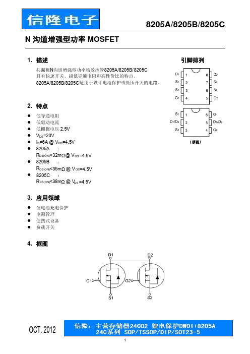
8205A/8205B/8205C
图1. 典型输出特性 (TBC=B 25℃)
图2. 典型输出特性(TBC=B 150℃)
图3. RDB S(ON)阻B 值与结温的关系
图4. 导通电阻与结温的归一化关系
图5. 反向二极管的正向特性 4
图6. 栅极门限电压与结温的关系
8205A/8205B/8205C
TrB B
TBd(off)B
TfB B
Ciss B
B
Coss B
B
Crss B
B
VSD B
B
ISB
B
VGS B
B
=
4.5V
8205A
IDB
=
B
4.5A
VGS B
B
=
2.5V
IDB
=
B
3.5A
VGS B
B
=
4.5V
8205B
IDB
=
B
4.5A
VGS B
B
=
2.5V
IDB
=
B
3.5A
VGS B
B
=
4.5V
Pb-Free
订购型号 8205A 8205B 8205C 8205ATR 8205BTR 8205CTR 8205AS6 8205BS6 8205CS6
包装数量 100 片/管 4000 片/卷 3000 片/卷
6. 最大额定参数
参数
符号
值
漏源电压 栅源电压 漏极电流,VBGS =B 4.5V,@TBaB=25°C 漏极电流,VBGS =B 4.5V,@TBaB=70°C 漏极脉冲电流(注1) 功耗,@TBaB=25°C 工作结温 存储温度 功耗随温升的线性降低因数
展讯系列各芯片组的参数

展讯系列各芯片组的参数
1. 展讯系列芯片组介绍
展讯公司是一家知名的处理器设计公司,其推出的展讯系列芯片组在市场上享有很高的声誉。
下面将介绍展讯系列各芯片组的参数。
2. 展讯芯片组A
•CPU型号:展讯A1
•CPU核心数:8核
•主频:2.5GHz
•GPU型号:Mali-G76
•内存支持:LPDDR4X
•制程工艺:10nm
展讯芯片组A是展讯公司最新推出的高性能芯片组,采用了先进的制程工艺和高性能的GPU,适合高端手机和平板电脑使用。
3. 展讯芯片组B
•CPU型号:展讯B1
•CPU核心数:4核
•主频:2.0GHz
•GPU型号:Mali-G52
•内存支持:LPDDR4
•制程工艺:12nm
展讯芯片组B是展讯公司推出的中端手机芯片组,性能稳定,适合大众消费者使用。
4. 展讯芯片组C
•CPU型号:展讯C1
•CPU核心数:6核
•主频:2.3GHz
•GPU型号:Mali-G57
•内存支持:LPDDR5
•制程工艺:8nm
展讯芯片组C是展讯公司推出的低功耗高性能芯片组,适合高性能要求和低功耗需求的设备使用。
5. 结语
展讯公司的各款芯片组在性能、功耗控制和成本方面均有不错表现,可以根据具体需求选择不同型号的芯片组。
展讯系列芯片组的不断创新与进步,将为消费者带来更好的使用体验。
以上就是展讯系列各芯片组的参数介绍。
以上Markdown文档则为关于展讯系列各芯片组的参数的内容,总字数超过1500字。
G8205-8205B

MOS FIELD EFFECT TRANSISTORG 8205 N-CHANNEL MOS FIELD EFFECT TRANSISTORDESCRIPTIONThe G8205 uses advanced trench technology to provideexcellent R DS(ON), low gate charge and operation with gate voltages as low as 2.5V. This device is suitable for use as a Battery protection or in other Switching application.GENERAL FEATURES● V DS = 20V,I D = 4A R DS(ON) < 45m Ω @ V GS =2.5V R DS(ON) < 30m Ω @ V GS =4V ● High Power and current handing capability ● Lead free product is acquired. ● Surface Mount PackageAPPLICATIONS● Battery protection ● Load switch● Power managementPACKAGE MARKING AND ORDERING INFORMATIONDevice MarkingDevicePackage Reel SizeTape widthQuantity8205 G8205 SOT23-6 Ø180mm 8mm 3000unitsABSOLUTE MAXIMUM RATLNGS(TA=25℃unless otherwise noted)Parameter Symbol Limit UnitDrain-Source Voltage V DS 20 VGate-Source VoltageV GS ±10 VI D 4 ADrain Current-Continuous@ Current-Pulsed (Note 1)I DM 25 AMaximum Power DissipationP D 1.25 WOperating Junction and Storage Temperature RangeT J ,T STG -55 to 150 ℃THERMAL CHARACTERISTICSThermal Resistance,Junction-to-Ambient (Note 2)R θJA 100 ℃/WELECTRICAL CHARACTERISTICS (TA=25℃unless otherwise noted)Parameter SymbolConditionMinTypMaxUnitOFF CHARACTERISTICSDrain-Source Breakdown Voltage BV DSS V GS =0V,I D =250µA 20VZero Gate Voltage Drain Current I DSS V DS =16V,V GS =0V 1 µA Gate-Body Leakage Current I GSS V GS =±10V,V DS =0V±100 nA ON CHARACTERISTICS (Note 3) Gate Threshold Voltage V GS(th) V DS =V GS ,,I D =250µA 0.5 0.8 1.2 V V GS =4V, I D =4A 27 30 m ΩDrain-Source On-State Resistance R DS(ON)V GS=2.5V, I D =3A 35 45 m Ω Forward Transconductanceg FS V DS =5V, I D =4A 10 SSchematic diagramMarking and pin AssignmentSOT23-6 top viewGTMOS TECH CO.,LTD. 2010.9.6 Version:1.1 Page 1 of 4Figure 1: Switching Test Circuit Figure 2: Switching WaveformsFigure 3: Normalized Maximum Transient Thermal ImpedanceSOT23-6 PACKAGE INFORMATIONDimensions in Millimeters (UNIT:mm)NOTES:1. All dimensions are in millimeters.2. Dimensions are inclusive of plating3. Package body sizes exclude mold flash and gate burrs. Mold flash at the non-lead sides should be less than 6 mils.4. Dimension L is measured in gauge plane.。
8205a芯片参数

8205a芯片参数
8205A 是一种四路运算放大器,广泛应用于电子系统中,例如充电宝、手机、电脑等。
它具有低失调电压、低噪声、低失真、大输出电流等特点。
在充电宝中,8205A 通常用于控制电池的充电和放电,以保持电池电压的稳定。
8205A 的参数如下:
- 输入电压范围:0.8V 至输入电压最大值
- 输出电压范围:0V 至输出电压最大值
- 输出电流:当输出电压为 3.6V 时,最大输出电流为 2A
- 失调电压:≤1mV
- 噪声电压:≤3mV
- 增益带宽积:≥5MHz
- 工作电流:置入电流≤5mA,输出电流≤2A
- 封装方式:SOT-23-5
要查询电子芯片的参数,可以下载一个集成电路查询软件,例如AIDA64 或 Integrated Collector。
这些软件可以查询各种元件的技术资料,包括芯片参数、电路图、供应商等。
此外,也可以在网上搜索相关的元件信息,例如在 TI 官网上搜索 8205A 芯片。
8205a中文资料

1.电池保护板的工作原理:锂电池保护板的电路和参数因IC和电压的不同而不同。
常用的保护芯片是8261,DW01 +,CS213,GEM5018等。
精工的8261系列具有更好的精度,当然也更昂贵。
后者来自台湾,国内二级市场主要使用DW01 +和CS213。
DW01 +使用MOS管8205A(8pin)给出以下说明:锂电池保护板的正常工作过程是:当电池电压在2.5V至4.3V之间时,DW01的第一和第三引脚输出高电平(等于电源电压),第二个引脚电压为0V。
此时,DW01的引脚1和引脚3的电压将分别施加到8205A的引脚5和引脚4上。
因为8205A中的两个电子开关的g极连接到DW01的电压,所以它们都处于导通状态,即两个电子开关都处于导通状态。
此时,电池单元的负极等效于与保护板的P-端子直接连通,并且保护板具有电压输出。
2.保护板的过放电保护控制原理:当电池通过外部负载放电时,电池的电压会逐渐降低,同时,电池的电压将通过R1电阻进行实时监控在DW01内部。
当电池电压降至约2.3V时,DW01会认为电池电压处于过放电电压状态,并立即断开第一引脚的输出电压,从而使第一引脚的电压变为0V,由于第5脚上没有电压,因此8205A中的开关管将闭合。
此时,电池芯的B-与保护板的P-断开。
即,当电池单元的放电电路被切断时,电池单元将停止放电。
保护板处于过放电状态,并一直保持。
在保护板的P-和P-间接施加了充电电压后,DW01在通过B-检测到充电电压后立即停止过放电,并再次在引脚1上输出高电压,从而打开了8205A中的过放电控制管。
即,电池芯的B-与保护板的P-重新连接,并且电池芯由充电器直接充电。
3.保护板过充保护控制原理:当充电器正常给电池充电时,随着充电时间的增加,电池单元的电压会越来越高。
当电池电压升至4.4V时,DW01会认为电池电压处于过充电电压状态,并立即断开第三个引脚的输出电压,从而使第三个引脚的电压变为0V,并且开关由于第四个引脚没有电压,因此8205A中的电子管关闭。
主流手机CPU及机型介绍

主流手机CPU及机型介绍!手机CPU生产厂商介绍!高通QSD8250、MSM8255、TI OMAP 3630、nVIDIA Tegra 2介绍2021年05月03日星期二13:25近年来随着智能手机的不断开展,其功能越来越强大,已经能处理很多原本只能在PC端完成的事情。
现在的智能手机已经算得上是一台超微型的电脑,从硬件结构上来看,CPU、内存、硬盘(存储器)、GPU等一个也不少。
或许未来的某一天,我们能像电脑一样自行组装一台手机。
现在许多厂商在推广手机产品的时候都打出“这手机采用1GHz主频高性能CPU〞等的宣传口号,没错,决定智能手机性能的一大因素就是他的“芯〞,但并不能以主频来简单划分CPU!以下笔者将给大家介绍一下现在主流手机CPU和其相关机型,方便大家选购。
目前主流的手机CPU可以分为单核(Cortex-A8)和双核(Cortex-A9),在同一工艺和主频下,双核CPU的性能一般均比单核的强,同时在多任务方面的性能也是单核CPU所不能到达的。
目前性能最强的手机CPU是三星i9100所采用的,Exynos4210,也叫猎户双核。
1.CPU生产厂商介绍传统的桌面处理器领域只有Intel和AMD两大巨头,而在手机处理器领域那么有多家厂商相互竞争,其中以高通、XX仪器、nVIDIA三家的规模和影响力最大。
高通(Qualcomm)公司以住给人的印象是在专利方面比拟知名,但是随着智能手机的不断开展,其手机硬件产品也逐渐成为市场的焦点。
高通公司旗下有著名的芯片组解决方案--Snapdragon,该方案结合了业内领先的3G/4G移动宽带技术与高通公司自有的基于ARM的微处理器内核、强大的多媒体功能、3D图形功能和GPS引擎。
而Snapdragon 众多芯片组中MSM7227、MSM7230、QSD8250、MSM8255等产品应用在许多的热门手机上,详细内容会在后面介绍。
XX仪器(Texas Instruments),简称TI,是全球领先的半导体公司,为现实世界的信号处理提供创新的数字信号处理(DSP)及模拟器件技术。
8205a与dw01工作原理

8205a与dw01工作原理一、引言本文将介绍8205a和d w01的工作原理。
8205a是一种电池保护IC芯片,而dw01是一种电池保护电路,它们在电池管理系统中起着重要作用。
本文将深入探讨8205a和d w01的原理及其在电池保护领域中的应用。
二、8205a的工作原理8205a是一种高集成度的电池保护I C芯片,其主要功能是监测电池的电压和电流,并在必要时切断电池的电源,以保护电池免受过充、过放、过流和短路等异常情况的损害。
8205a通常由以下几个模块组成:1.电压检测模块8205a内置了一组电压检测模块,用于监测电池的电压。
当电池电压低于一定阈值时,8205a将触发保护机制,切断电池的输出,以避免过放。
2.电流检测模块8205a还内置了一组电流检测模块,用于监测电池的电流。
当电池电流超过设定的最大允许值时,8205a将切断电池的输出,以避免过流。
3.温度检测模块8205a还包含了一个温度检测模块,用于监测电池的温度。
当电池温度超过设定的安全范围时,8205a将采取相应措施,以确保电池的安全运行。
三、d w01的工作原理d w01是一种用于电池保护的集成电路,它通常与8205a等电池保护I C芯片配合使用。
dw01主要负责控制电池的充放电过程,以保护电池的安全性和延长其使用寿命。
d w01的工作原理主要包括以下几个方面:1.充电控制d w01通过监测电池的电压和电流,控制充电过程。
当电池的电压接近充满时,dw01将停止充电,以避免过充。
同时,dw01还可监测充电电流,以防止充电电流超过设定的最大允许值,保证充电的安全性。
2.放电控制d w01能够监测电池的电压和电流,控制放电过程。
当电池的电压降至一定阈值以下时,dw01将自动切断电池的输出,以避免过放。
同时,d w01还可监测放电电流,以保证放电电流不会超过设定的限制,确保电池的安全运行。
3.温度控制d w01还配备了温度传感器,可以实时监测电池的温度。
GTS8205芯片性能及参数介绍

GTM
CORPORATION
ISSUED DATE: 2004/10/18 REVISED DATE:
Fig 13. Switching Time Circuit
Fig 14. Switching Time Waveform
Fig 15. Gate Charge Circuit
Fig 16. Gate Charge Waveform
Important Notice: All rights are reserved. Reproduction in whole or in part is prohibited without the prior written approval of GTM. GTM reserves the right to make changes to its products without notice. GTM semiconductor products are not warranted to be suitable for use in life-support Applications, or systems. GTM assumes no liability for any consequence of customer product design, infringement of patents, or application assistance. Head Office And Factory: Taiwan: No. 17-1 Tatung Rd. Fu Kou Hsin-Chu Industrial Park, Hsin-Chu, Taiwan, R. O. C.
GTS8205
Page: 5/5
- 1、下载文档前请自行甄别文档内容的完整性,平台不提供额外的编辑、内容补充、找答案等附加服务。
- 2、"仅部分预览"的文档,不可在线预览部分如存在完整性等问题,可反馈申请退款(可完整预览的文档不适用该条件!)。
- 3、如文档侵犯您的权益,请联系客服反馈,我们会尽快为您处理(人工客服工作时间:9:00-18:30)。
Fig 6. Type Power Dissipation
Page: 3/5
GTM
CORPORATION
ISSUED DATE: 2004/10/18 REVISED DATE:
Fig 7. Maximum Safe Operating Area
Fig 8. Effective Transient Thermal Impedance
Static Drain-Source On-Resistance Total Gate Charge2 Gate-Source Charge Gate-Drain (“Miller”) Change Turn-on Delay Time Rise Time Turn-off Delay Time Fall Time Input Capacitance Output Capacitance Reverse Transfer Capacitance
Features
*Low on-resistance *Capable of 2.5V gate drive *Low drive current *Surface mount package *RoHS Compliant
Package Dimensions
REF. A A1 b c D
Millimeter Min. Max.
GTS8205
Page: 5/5
Operating Junction and Storage Temperature Range
Thermal Data
Parameter Thermal Resistance Junction-ambient Max. Symbol Rthj-a Value 125 Unit ℃/W
GTS8205
GTM
GTS 8205
Pb Free Plating Product
CORPORATION
ISSUED DATE: 2004/10/18 REVISED DATE:
DUAL N-CHANNEL ENHANCEMENT MODE POWER MOSFET
BVDSS RDS(ON) ID
20V 25mΩ 6A
Description
The GTS8205 provides the designer with the best combination of fast switching, ruggedized device design, ultra low on-resistance and cost-effectiveness.
1,2 3 3
Symbol VDS VGS ID @Ta=25℃ ID @Ta=70℃ IDM PD @Ta=25℃ Tj, Tstg
Ratings 20 ±12 6 4.5 20 1 0.008 -55 ~ +150
Unit V V A A A W W/℃ ℃
Total Power Dissipation Linear Derating Factor
Important Notice: All rights are reserved. Reproduction in whole or in part is prohibited without the prior written approval of GTM. GTM reserves the right to make changes to its products without notice. GTM semiconductor products are not warranted to be suitable for use in life-support Applications, or systems. GTM assumes no liability for any consequence of customer product design, infringement of patents, or application assistance. Head Office And Factory: Taiwan: No. 17-1 Tatung Rd. Fu Kou Hsin-Chu Industrial Park, Hsin-Chu, Taiwan, R. O. C.
Page: 1/5
GTM
Parameter Drain-Source Breakdown Voltage
Breakdown Voltage Temperature Coefficient
CORPORATION
Min. 20 0.5 Typ. 0.1 9.7 12.5 1 6.5 5 9 26.2 6.8 355 190 85 Max. ±10 1 25 25 40 pF ns nC Unit V V/℃ V S uA uA uA mΩ
Fig 9. Gate Charge Characteristics
Fig 10. Typical Capacitance Characteristics
Fig 11. Forward Characteristics of Reverse Diode
GTS8205
Fig 12. Gate Threshold Voltage v.s. Junction Temperature
GTS8205
Page: 2/5
GTM
Characteristics Curve
CORPORATION
ISSUED DATE: 2004/10/18 REVISED DATE:
Fig 1. Typical Output Characteristics
Fig 2. Typical Output Characteristics
ISSUED DATE: 2004/10/18 REVISED DATE:
Electrical Characteristics(Tj = 25℃ Unless otherwise specified)
Symbol BVDSS
∆BVDSS /∆Tj
Test Conditions VGS=0, ID=250uA Reference to 25℃, ID=1mA VDS=VGS, ID=250uA VDS=10V, ID=6A VGS= ±10V VDS=20V, VGS=0 VDS=20V, VGS=0 VGS=4.5V, ID=4A VGS=2.5V, ID=2A ID=4.6A VDS=20V VGS=5V VDD=10V ID=1A VGS=5V RG=3.3Ω RD=10Ω VGS=0V VDS=20V f=1.0MHz
Gate Threshold Voltage Forward Transconductance Gate-Source Leakage Current
Drain-Source Leakage Current(Tj=25℃) Drain-Source Leakage Current(Tj=70℃)
VGS(th) gfs IGSS IDSS
Fig 3. On-Resistance v.s. Gate Voltage
Fig 4. Normalized On-Resistance v.s. Junction Temperature
Fig 5. Maximum Drain Current v.s. Case Temperature
GTS8205
Page: 4/5
GTM
CORPORATION
ISSUED DATE: 2004/10/18 REVISED DATE:
Fig 13. Switching Time Circuit
Fig 14. Switching Time Waveform
Fig 15. Gate Charge Circuit
Fig 16. Gate Charge Waveform
2
RDS(ON) Qg Qgs Qgd Td(on) Tr Td(off) Tf Ciss Coss Crss
Source-Drain Diode
Parameter Forward On Voltage2
Continuous Source Current(Body Diode) Continuous Source Current(Body Diode)
1
Symbol VSD IS ISM
Min. -
Typ. -
Max. 1.2 1.25 20
Unit V A A
Test Conditions IS=1.25, VGS=0V, Tj=25℃ VD= VG=0V, VS=1.2V
Notes: 1. Pulse width limited by Max. junction temperature. 2. Pulse width≤300us, duty cycle≤2%. 3. Surface mounted on FR4 board, t≤10sec.
0.05 0.19 0.09 2.90 1.20 0.15 0.30 0.20 3.10
REF. E E1 e L S
Millimeter Min. Max.
6.20 4.30 0.45 0° 6.60 4.50 0.75 8°
0.65 BSC
Absolute Maximum Ratings
Parameter Drain-Source Voltage Gate-Source Voltage Continuous Drain Current , VGS@10V Continuous Drain Current , VGS@10V Pulsed Drain Current
