思科IPS产品线安装部署指南V2
思科 FindIT Network Discovery Utility 2.0 快速入门指南说明书
Cisco Systems, Inc. 思科在全球设有 200 多家办事机构。
地址、电话号码和传真号码 均在思科网站上列出,网址为: /go/offices 。
思科 Small BusinessCisco FindIT Network Discovery Utility 版本 2.0快速入门指南文本部件编号: 78-21387-02本手册中的规定和信息如有变更,恕不另行通知。
我们相信本手册中的所有声明、信息和建议均准确可靠,但不提供任何明示或暗示的担保。
用户应承担使用产品的全部责任。
产品配套的软件许可证和有限担保在随产品一起提供的信息包中提供,且构成本文的一部分。
如果您找不到软件许可或有限担保,请与思科代表联系以索取副本。
思科执行的 TCP 报头压缩是对加州大学伯克利分校 (UCB) 开发的某一程序的修改,它是 UNIX 操作系统的 UCB 公用版的一部分。
保留所有权利。
Copyright © 1981,加利福尼亚州大学董事会。
无论本手册中是否有任何其他担保,这些供应商的所有文档文件和软件均按“原样”提供,可能包含缺陷。
思科及其上述供应商不承担任何明示或暗示的担保, 包括(但不限于)商品适销性、对特定用途的适用性、非侵权担保,或因任何交易、使用或贸易行为而产生的担保责任。
在任何情况下,对于任何间接、特殊、连带发生或偶发的损坏,包括(但不限于)因使用或无法使用本手册而导致的任何利润损失或数据损失/损坏,思科及其供应商概不负责,即使思科及其供应商已获知此类损坏的可能性也不例外。
思科和思科徽标是思科和/或其附属公司在美国和其他国家/地区的注册商标。
要查看思科的商标列表,请访问此 URL:/go/trademarks。
文中提及的第三方商标为其相应所有人的财产。
使用“合作伙伴”一词并不暗示思科和任何其他公司之间存在合作关系。
(1110R)本文档中使用的任何互联网协议 (IP) 地址和电话号码并不代表实际地址和电话号码。
Cisco设备安装指南

Distribution 一般不会本层使用. Layer
分布层
提供访问层与分布层之间的连接. 提供从分 布层到核心层的连接. 提供从服务器群到核 心层的连接.
Co核re心L层ayer 一般不会在本层使用.
提供交换机间的互连.
以太网介质比较
10BaseT
双工型介质接口 连接器 (MIC) ST
区分不同的连接类型
棕 棕 绿 蓝蓝 绿 橙橙 白白 白白
两端的线序相同
UTP实现交叉线
交叉连接10BaseT/ 100BaseT
交叉线
集线器/交换机
针线 1 RD+ 2 RD3 TD+ 4 NC 5 NC 6 TD7 NC 8 NC
集线器/交换机
针线 1 RD+ 2 RD3 TD+ 4 NC 5 NC 6 TD7 NC 8 NC
DTE
Data Communications Equipmen 数据通讯设备
• WAN服务商方的最后通讯设备 • DCE提供时钟
DCE
调制解调器 通道服务单元/ 数据服务单元
SS
S
S
SS
DTE
DCE
DCE
DTE
• DTE/DCE—责任分界点
固化的端口
2500 路由器—背板一览
WAN串口可以采用固化方式
图例
快速以太网/ 以太网 ISDN 专线
核心 服务器
ISDN 云
专线/ 帧中继
WAN物理层实现
• 物理层实现多种多样 • 连线规范定义了连接速率
HDLC PPP 帧中继
EIA/TIA-232 EIA/TIA-449 X.121 V.24 V.35
HSSI
Cisco IPS(5.x)配置操作详解

Cisco IPS(5.x)配置操作详解2010-02-10 23:38:10 来源: 【大中小】文章摘要:一、IPS Initual 1.使用管理员账号登陆IPS,默认下,用户名/密码:cisco/cisco;如果你是第一次登陆该IPS,那么IPS会提示你改变默认密码;2.使用setup命令,进入对话框配置--- System Configur-一、IPS Initual1.使用管理员账号登陆IPS,默认下,用户名/密码:cisco/cisco;如果你是第一次登陆该IPS,那么IPS会提示你改变默认密码;2.使用setup命令,进入对话框配置--- System Configuration Dialog ---At any point you may enter a question mark '?' for help.User ctrl-c to abort configuration dialog at any prompt.Default settings are in square brackets '[]'.Current Configuration:service hostnetwork-settingshost-ip 10.1.9.201/24,10.1.9.1host-name sensortelnet-option disabledftp-timeout 300login-banner-textexittime-zone-settingsoffset 0standard-time-zone-name UTCexitsummertime-option disabledntp-option disabledexitservice web-serverport 443exitCurrent time: Wed May 5 10:25:35 2004Continue with configuration dialog?[yes]:输入yes或直接回车,进入配置对话框;配置完成后使用show configuration验证配置;二、Setting UP the Sensor2.1 Configuring Network Settings使用Network面板来配置sensor的网络参数和通信参数;路径:Configuration > Sensor Setup > Networkl Hostname——设置sensor的名字;l IP Address——设置sensor的IP地址,默认地址是10.1.9.201;l Network Mask——默认掩码是255.255.255.0l Default Route——指定默认网关;默认是10.1.9.1l Ftp Timeout——当sensor和FTP Server通信的时候,指定FTP Client在超时之前等待时间,默认是300秒;l Web Server Settings——设置web server安全级别和接口参数—Enable TLS/SSL——在web server上启用TLS和SSL加密;默认下是启用的;—Web server port——Web Server使用的TCP接口号;默认为443;l Remote Access——启用sensor的远程接入—Enable Telnet——启用或禁用Sensor的Telnet管理,默认为禁用;图例:2.2 Configuring Allowed Hosts配置允许访问Sensor的主机地址或网段;路径:Configuration > Sensor Setup > Allowed Hosts;l IP Address——允许访问sensor的IP地址;l Network Mask——掩码决定是主机地址还是网段;图例:2.3 Configuring SSHSSH提供安全的接入和认证,SSH加密到sensor的连接,并提供对接入用户的认证,SSH 同时也提供sensor和其他设备联动时的认证和加密;SSH使用以下的任何一种方法认证主机:l Password;l 用户RSA public key;2.3.1 Defining Authorized Keys为客户端使用RSA认证方法登陆SSH server,定义client的public keys;在client上使用RSA key产生工具产生公钥/密钥,将公钥提交给SSH server;配置路径:Configuration > Sensor Setup > SSH > Authorized Keys(这个配置是用于client 通过ssh 登录ips.并且一旦配置完毕key就不需要密码了.认证的途径叫rsa authentication)图例:2.3.2 Defining Known Host Keys在该域下,定义当Sensor SSH到其他设备上的时候,其他设备的Pbulic Keys;把要登陆设备的IP地址填入之后,点Retrieve Host Key,Sensor将会自动将目标设备的Pbulic Key接收回来;配置路径:Configuration > Sensor Setup >SSH > Known Host Keys.2.3.3 Sensor KeyIPS Sensor自身SSH key,你可以使用Generate Key按钮重新产生一个新的Sensor SSH key;路径:Configuration > Sensor Setup > SSH > Sensor Key2.4 Configuring Certificates2.4.1 Trusted Hosts增加主block sensors或Sensor下载更新时的TLS和SSL服务器的证书,你可以通过写入IP 地址,然后Sensor会将目标的证书接收回来;路径:Configuration > Sensor Setup > Certificate > Trusted Hosts;2.4.2 Server Certificate服务器自身的证书;2.5 Configuring Users用户有以下角色:l Administrators——最高权限,可以察看并修改所有配置;l Operators——可以察看配置和事件,但是只能够修改以下选项:—Signature tuning (priority,disable or enable)—Virtual sensor definition—Managed routers—Their user passwordsl Viewers——可以察看所有配置和事件,但是不能够修改任何配置,除了他们的密码外;l Service——特殊账号,可以进入IPS内核程序;路径:Configuration > Sensor Setup > Users三、Configuring Interfaces我们可以将sensing接口运行在混杂模式,也可以将接口配置为inline pairs,但是首先要将接口UP;Sensing 接口没有IP地址,因此该接口对于攻击者来说是不可见的。
Cisco 7304 MSC和SPA硬件安装指南说明书
C H A P T E R2-1Cisco 7304 MSC and SPA Hardware Installation GuideOL-4681-012Overview: Cisco 7304 Router Carrier CardsThis chapter describes the carrier cards that are supported on the Cisco 7304 router and contains the following sections:•Carrier Card and SPA Compatibility, page 2-1•Carrier Card Summary, page 2-1•MSC-100 Overview, page 2-2Carrier Card and SPA CompatibilityFor information on carrier card and SPA compatibility, see the “MSC and SPA Compatibility” section on page 1-2.Carrier Card SummarySummary descriptions of the carrier cards that are supported on the Cisco 7304 router are shown in Table 2-1.T able 2-1Carrier Card SummaryCarrier Card Product Number DescriptionNumber of SPAs Minimum Cisco IOS Release MSC-1007304-MSC-100Modular Services Card 1002Release 12.2(20)S2Chapter2 Overview: Cisco 7304 Router Carrier Cards MSC-100 OverviewChecking Hardware and Software CompatibilityTo check the minimum software requirements of Cisco IOS software with the hardware installed on yourrouter, Cisco maintains the Software Advisor tool on . This tool does not verify whethercarrier cards or SPAs within a system are compatible, but it does provide the minimum Cisco IOSrequirements for individual hardware modules or components.Note Access to this tool is limited to users with login accounts.To access Software Advisor, click Login at , type “Software Advisor” in the SEARCH box,and click GO. Click the link for the Software Advisor tool.Choose a product family or enter a specific product number to search for the minimum supportedsoftware release needed for your hardware.SPA Blank Filler PlatesSPA blanks are available to fill and unused SPA slot.Note When a SPA slot is not in use, a SPA blank filler plate must fill the empty slot to allow the router or switch to conform to electromagnetic interference (EMI) emissions requirements and to allow properairflow across the SPAs. If you plan to install a new SPA in a slot that is not in use, you must first removethe SPA blank filler plate.MSC-100 OverviewThe following sections describe the MSC-100:•Board Components, page 2-2•LEDs, page 2-4•Physical Specifications, page 2-5•Carrier Card Slot Locations on the Cisco 7304 Router, page 2-5•SPA Slot Numbering on the MSC-100, page 2-5•SPA Interface Addresses on MSCs, page 2-6Board ComponentsThe main MSC-100 board components are shown in Figure2-1.Cisco 7304 MSC and SPA Hardware Installation GuideOL-4681-012-3Cisco 7304 MSC and SPA Hardware Installation GuideOL-4681-01Chapter 2 Overview: Cisco 7304 Router Carrier CardsMSC-100 Overview2-4Cisco 7304 MSC and SPA Hardware Installation GuideOL-4681-01Chapter 2 Overview: Cisco 7304 Router Carrier CardsMSC-100 Overview2-5Cisco 7304 MSC and SPA Hardware Installation GuideOL-4681-01Chapter 2 Overview: Cisco 7304 Router Carrier CardsMSC-100 OverviewChapter2 Overview: Cisco 7304 Router Carrier Cards MSC-100 OverviewSPA Interface Addresses on MSCsInterface addresses specify the physical location of each interface on a router or switch. Table2-4describes how to identify the interface addresses for SPAs supported on the MSC-100.T able2-4Address FormatMSC Address Format DescriptionMSC-100router-module-slot/subslot/SPA-port-number Router module slot—2 through 5. Specifiesthe slot on the Cisco 7304 router where theMSC-100 is installed.subslot—Top (0) or bottom (1) subslot.Specifies the subslot in the MSC-100 that isholding the SPA.SPA-port-number—Varies. Specifies the portnumber on the SPA to address.Cisco 7304 MSC and SPA Hardware Installation GuideOL-4681-01。
思科
Cisco 思科产品线介绍时间: 2010-08-23 / 分类: +思科业界新闻, ★CISCO技术/ 浏览次数: 546 views / 1个评论发表评论网络的重要作用日益凸显,包括各类IT、通信技术都纷纷向这个平台转移,这让思科扩大潜在市场变得触手可及,无可动摇的坐上了全球网络设备的领头羊的位置!思科作为网络设备的领头军,很多时候都是在制定行业标准,因此客户才会愿意去使用思科的产品,思科的产品是通用产品他满足了企业和消费者的需求。
本公司面向全国cisco分销商和最终客户,寻求与系统集成商友好长久合作。
公司有交换机路由器防火墙大量库存,贵公司如有需求,可以来电话,假如能够认识,即便做不了生意,可以交个朋友,工作不忙的时候可以聊聊。
从心里希望大家都生活幸福.生意兴隆。
您需要产品的时候欢迎来电或MSN QQ联系!我们将会为您提供最有竞争力的价格最优的质量和最优质的服务!思科代理商官方博客:如有相关需求欢迎和我联系,我们将全力为您的项目提供支持以下是思科大部分产品型号介绍,以便于您的查找。
一路由器产品一览(1)Cisco 800 系列集成多业务路由器允许小型机构以宽带速度运行安全并发服务,包括防火墙、VPN 和无线局域网●无线支持:850 和870 系列上提供了可选IEEE 802.11 b/g●增强安全特性,包括状态化检测防火墙和硬件辅助加密(830 和870 系列),以及用于VoIP 的QoS特性● DMZ、拨号备份和带外管理(Cisco 830、850 和870 系列)●安全设备管理器(SDM)GUI 工具,用于简单和高级配置CISCO871-K9 CISCO871W-G-E-K9 CISCO871-SEC-K9CISCO876-K9 CISCO877-K9 CISCO878-SEC-K9(2)Cisco 1800 系列模块化固定架构——提供多种局域网和广域网选项;Cisco 1841上的网络接口能够现场升级,提供了灵活性,并可支持未来技术●固定配置路由器型号提供了10/100 以太网、ADSL over ISDN、ADSL over POTS,或配备集成ISDNBRI 的G.SHDSL 广域网接口(1801、1802、1803 和1812)或模拟调制解调器(1811)备份接口● 1800 系列的所有型号都通过IEEE 802.11 a/b/g 提供无线局域网接入功能CISCO1841 CISCO1841-T1 CISCO1802 CISCO1841-SEC/K9CISCO1801 CISCO1801/K9 CISCO1802/K9 CISCO1841-HSEC/K9(3)Cisco 2800 系列经过了优化的集成多业务路由器,能为中小型企业和大型企业分支机构路由安全、线速地供应数据、语音和视频并发服务●为1 到6 条T1/E1 连接提供出色性能,支持多项服务●高级安全特性,包括状态化防火墙、IPS、VPN 和NAC●凭借DES、3DES 和AES 提供内置加密功能●支持IEEE 802.11 a/b/g WLAN 的无线接入点CISCO2801 CISCO2811 CISCO2821 CISCO2851CISCO2801-SEC/K9 CISCO2801-HSEC/K9 CISCO2811-SEC/K9CISCO2811-HSEC/K9CISCO2821-SEC/K9 CISCO2821-HSEC/K9 CISCO2851-SEC/K9CISCO2851-HSEC/K9CISCO2801-V/K9 CISCO2801-CCME/K9 CISCO2811-V/K9CISCO2811-CCME/K9CISCO2821-V/K9 CISCO2821-CCME/K9 CISCO2851-V/K9CISCO2851-CCME/K9(4)Cisco 3800 系列集成多业务路由器●最高的性能和密度,能够以高达T3/E3 的线速运行并发数据、安全、语音和高级服务●更高的可用性和永续性,具有热插拔功能(OIR);冗余系统和馈线电源选项●高速广域网接口卡(HWIC)为其他服务留出了网络模块插槽●增强安全性●扩展缺省和最大内存容量,ECC(错误纠正代码)DDR SDRAM内存能够检测和纠正SDRAM错误,无需用户介入CISCO3825 CISCO3825-AC-IP CISCO3825-DCCISCO3845 CISCO3845-AC-IP CISCO3845-DCCISCO3825-V/K9 CISCO3825-CCME/K9 CISCO3845-V/K9CISCO3845-CCME/K9CISCO3825-SEC/K9 CISCO3845-SEC/K9 CISCO3825-HSEC/K9CISCO3845-HSEC/K9(5)Cisco 7200 系列以小巧机箱提供智能服务、高度模块化特性、高性能、投资保护和可扩展性的优化的OC3/GE广域网边缘路由器●模块化的3RU 机箱● 4 或者6 插槽型号,用于端口适配器● 1 个I/O 插槽●可以选择系统处理器(NPE),速度最高可达1Mpps●内置千兆以太网连接(NPE-G1 上的3 个端口)(铜缆或光纤)●广泛的局域网和广域网选项,包括以太网、快速以太网、千兆以太网、令牌环网、串行、ISDN、HSSI、ATM、SONET 分组,以及包括IP-IP 网关和QoS 在内的语音支持。
Cisco IPS的几种部署方式
Cisco IPS的几种部署方式By 逆流风(2011/02/02)最近在看现任明教教主的IPS视频教程。
看视频然后做实验,发现网上Cisco安全方面的资料很少,尤其是IPS方面的,很多东西得自己去Cisco官网上面自己看,可怜我425分的四级英语水平,而且那些配置又不给个Example,特此做下笔记,以备后用。
Inline Bypass ModeYou can use inline bypass as a diagnostic tool and a failover protection mechanism. Normally, the sensor Analysis Engine performs packet analysis. When inline bypass is activated, Analysis Engine is bypassed, allowing traffic to flow through the inline interfaces and inline VLAN pairs without inspection. Inline bypass ensures that packets continue to flow through the sensor when the sensor processes are temporarily stopped for upgrades or when the sensor monitoring processes fail. There are three modes: on, off, and automatic. By default, bypass mode is set to automatic.摘自Cisco,说的是内联旁路模式(Inline Bypass Mode,不知道翻译对不对)有三种模式,on,off和auto(默认是auto),当启用Inline Bypass Mode时,也就是on的话,数据包不会被分析引所检测,当分析引擎故障失效时,数据包可以继续通过。
V2416快速安装指南说明书
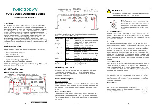
P/N: 1802024160011V2416 Quick Installation GuideSecond Edition, April 2014OverviewThe V2416 Series embedded computers are based on the Intel Atom N270 x86 processor and feature 4 RS-232/422/485 serial ports, dual LAN ports, and 3 USB 2.0 hosts. In addition, the V2416 computers provide VGA and DVI-I outputs and are EN 50155 certified to confirm their robustness for railway and industrialapplications. 2 hot-swappable and removable storage trays are also provided for convenient, fast and easy storage expansion. The V2416 also features user-defined programmable LEDs and an associated API for storage management, supporting storageplug/unplug functionality, automatic storage removal, and storage status display. An API Library is included for easy development and storage capacity notification.Package ChecklistBefore installing, verify that the package contains the following items:• V2416 embedded computer. • Wall mounting kit• PS2 to KB/MS Y-type cable• Documentation and Software CD or DVD • Quick installation guide (printed)• Product Warranty Statement (printed)NOTE: Please notify your sales representative if any of the above items are missing or damaged.V2416 Panel LayoutV2416 Front & Rear ViewsLED IndicatorsThe following table describes the LED indicators located on the front and rear panels of the V2416. LED Name LED Color LED FunctionPower Green Power is on and functioning normally OffPower is off, or power error exists Storage Yellow CF/HDD card is detectedOff CF/HDD card is not detected LAN (1, 2)Green 100 Mbps Ethernet mode Yellow1000 Mbps Ethernet mode Off 10 Mbps or no activityTx (P1-P4)Green Serial ports P1-P4 transmitting data Off Serial ports P1-P4 not transmitting dataRx (P1-P4) Yellow Serial ports P1-P4 receiving data Off Serial ports P1-P4 not receiving data X2 (Disk 1, Disk 2)Yellow User-programmable OffUser-programmableInstalling the V2416The V2416 can be DIN-rail mounted, wall mounted, and VESA mounted. Some mounting kits may need to be purchased separately. Refer to the Hardware User’s Manual for detailed installation instructions.Connector DescriptionPower ConnectorConnect the 12 to 48 VDC power line with M12 connectors to the V2416 computer. If the power is supplied properly, the Power LED will light up. The OS is ready when the Ready LED glows a solid green.Grounding the V2416Grounding and wire routing help limit the effects of noise due to electromagnetic interference (EMI). Run the ground connection from the ground screw to the grounding surface prior to connecting the power.V2416SG: The Shielded Ground (sometimes called Protected Ground) contact is the central pin of the power input connector. Connect the SG wire to an appropriate grounded metal surface.VGA and DVI OutputsThe V2416 comes with a D-Sub 15-pin female connector for a VGA monitor; it also comes with a DVI-I connector for the DVI display. These output interfaces are all located on the front panel. Use the proper cable to connect. PS/2 PortThe V2416 embedded computer comes with a PS/2 mini-DINconnector to connect to a PS/2 keyboard and PS/2 mouse. Use the Y-type cable to convert the mini-DIN connector into two 6-pin mini-DIN connectors to connect both a PS/2 keyboard and PS/2 mouse at the same time. You may also use the USB ports to connect your USB-based keyboard and mouse. Please note that without a Y-type cable, the PS/2 connector on the V2416 can only work with a PS/2 keyboard. A PS/2 mouse will not function when directly connected to the PS/2 connector on the V2416 embedded computer.CompactFlash SlotThe V2416 has a CompactFlash slot located on the front panel for storage expansion. It supports CF Type-I/II with DMA mode. To install a CompactFlash card, remove the outer cover, and then insert the CF card in the socket. When finished, push the cover into the socket and fasten the screws. USB HostsThe V2416 has one USB port with a M12 connector on the front panel, and two USB ports with type A connectors on the rear panel. These USB ports can be used to connect flash disks for storing large amounts of data. Ethernet PortsTwo 10/100/1000 Mbps Ethernet ports using M12 connectors are located on the front panel. See the following pin assignments./supportThe Americas: +1-714-528-6777 (toll-free: 1-888-669-2872)Europe: +49-89-3 70 03 99-0 Asia-Pacific: +886-2-8919-1230China: +86-21-5258-9955 (toll-free: 800-820-5036)2014 Moxa Inc., All Rights Reserved10/100 Mbps1000 MBps 1 -- TRD3+ 2 -- TRD4+ 3 -- TRD4- 4 ERx- TRD1- 5 ETx+ TRD2+ 6 ERx+ TRD1+ 7 -- TRD3- 8 ETx-TRD2-Serial PortsThe serial ports use DB9 connectors. Each port can be configured by software for RS-232, RS-422, or RS-485. The pin assignments for the ports are shown in the following table: Pin RS-232 RS-422 RS-485 (4-wire) RS-485 (2-wire) 1 DCD TxDA(-) TxDA(-) --- 2RxD TxDB(+) TxDB(+) ---3 TxD RxDB(+) RxDB(+) DataB(+)4 DTR RxDA(-) RxDA(-) DataA(-)5 GND GND GND GND6 DSR --- --- ---7 RTS --- --- --- 8CTS---------Audio InterfaceThe V2416 comes with an audio input and an audio output, allowing users to connect a speaker or an earphone. DI/DOThe V2416 comes with a 6-ch digital input and 2-ch digital output in the terminal block connectors.Hot-swappable and removable Storage TraysThe V2416 computers come with 2 removable slots for inserting additional storage media; it also supports hot swapping forconvenient, fast, and easy storage expansion. The user-defined programmable LEDs and the associated API for storagemanagement support storage plug/unplug functionality, automatic storage removal, and storage status display. Refer to the Hardware User's Manual for detailed storage installation. Reset ButtonPress the “Reset Button” on the rear panel of the V2416 to reboot the system automatically. The Ready LED will blink on and off for the first 5 seconds, and then maintain a steady glow once the system has rebooted.Real-time ClockThe V2416’s real-time clock is powered by a lithium battery. We strongly recommend that you do not replace the lithium battery without help from a qualified Moxa support engineer. If you need to change the battery, contact the Moxa RMA service team.Powering on the V2416To power on the V2416, connect the power cable to the V2416’s M12 power connector (located at the rear panel). Press the power button to turn on the computer. Note that the Shielded Ground wire should be connected to the central pin of the connector. It takes about 30 seconds for the system to boot up. Once the system is ready, the Power LED will light up.Configuring the Ethernet InterfacePower on the V2416 computer after connecting a monitor,keyboard, and mouse, and verifying that the power source is ready. Once the operating system boots up, the first step is to configure the Ethernet interface. The factory default settings for the V2416 LANs are show below. (Please note that the XPE and W7E models use DHCP settings.)Default IP Address NetmaskLAN1 192.168.3.127 255.255.255.0 LAN2 192.168.4.127255.255.255.0Linux users should follow these steps:If you are using the console cable for first-time configuration of the network settings, enter the following commands to edit the interfaces file:#ifdown –a//Disable LAN1/LAN2 interface first, before youreconfigure the LAN settings. LAN 1 = eth0, LAN 2= eth1,#vi /etc/network/interfaces//check the LAN interface first// After the boot settings of the LAN interface have been modified, use the following command to activate the LAN settings immediately:#sync; ifup –aXPE users should follow these steps:1. Go to Start Network Connections .2. Right-click Network Connections , click Properties . Next,select Internet Protocol (TCP/IP), and then click Properties .3. Click OK after inputting the proper IP address and netmask.W7E users should follow these steps:1. Go to Start -> Control Panel-> Network and Internet ->View network status and tasks -> Change adapter setting .2. In the screen of Local Area Connection Properties, clickInternet Protocol (TCP/IP) and then select Properties . Select Internet Protocol Version 4, and then click Properties .3. Click OK after inputting the proper IP address and netmask. NOTE: Refer to the User’s Manual for other configuration information.。
思科 ISE 网络部署 网络配置和部署指南说明书

思科ISE中的网络部署•Cisco ISE网络架构,第1页•Cisco ISE部署术语,第1页•分布式部署中的节点类型和角色,第2页•独立和分布式ISE部署,第3页•分布式部署方案,第3页•小型网络部署,第4页•中型网络部署,第5页•大型网络部署,第6页•每个部署模式的最大支持会话数,第8页•支持Cisco ISE功能所需的交换机和无线局域网控制器配置,第10页Cisco ISE网络架构Cisco ISE架构包括以下组件:•节点和角色类型•Cisco ISE节点-Cisco ISE节点可以承担以下任意或所有角色:管理、策略服务、监控或pxGrid•网络资源•终端策略信息点表示外部信息传达给策略服务角色所在的点。
例如,外部信息可以是轻量级目录访问协议(LDAP)属性。
Cisco ISE部署术语本指南在讨论Cisco ISE部署方案时使用以下术语:定义术语角色提供的特定功能,例如网络访问、分析、状态、安全组访问、监控和故障排除。
服务单个物理或虚拟思科ISE 设备。
节点思科ISE 节点可以承担下列任何角色:管理、策略服务、监控节点类型确定节点提供的服务。
思科ISE 节点可以承担以下任一或全部角色:。
通过管理用户界面可使用的菜单选项取决于节点承担的角色和人员。
角色确定节点是独立节点、主要节点还是辅助节点,并且仅适用于管理和监控节点。
角色分布式部署中的节点类型和角色Cisco ISE 节点可以根据它承担的角色提供各种服务。
部署中的每个节点均可承担管理、策略服务、pxGrid 和监控角色。
在分布式部署中,您可以在网络中使用以下节点组合:•实现高可用性的主要和次要管理节点•实现自动故障切换的监控节点对•实现会话故障切换的一个或多个策略服务节点•pxGrid 服务的一个或多个pxGrid 节点管理节点通过具有管理角色的Cisco ISE 节点,您可以在Cisco ISE 上进行所有管理操作。
它处理与诸如身份验证、授权和记帐等功能有关的所有系统相关配置。
Cisco IPS配置
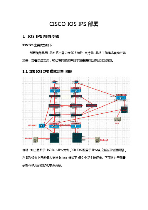
CISCO IOS IPS部署1IOS IPS部署步骤IOS IPS主要优势如下:部署简单易用,思科路由器内嵌IOS特性支持INLINE工作模式自动拦截攻击,部署简单实用,轻松在网络边界对于攻击进行动态过滤及防范。
1.1ISR IOS IPS模式部署图例说明:如上图所示ISR IOS IPS为例,ISR IOS配置于IPS模式监控及管理网络,在ISR设备上目前最大支持Inline 模式下650个IPS特征库。
下面将对于配置步骤作相应的说明和要点总结。
1.2ISR IOS IPS部署概述1.2.1配置ISR路由器更新软件首先更新ISR路由器软件版本以便支持IPS特性,您需要升级您的至Cisco IOS Release 12.3(8)T or later。
1.2.2配置ISR路由器SDF文件ISR路由器软件版本内嵌了一定数量的IPS Signatures,您需要下载最新的SDF文件并且与IOS内嵌的IPS Signatures进行合并操作,以便实现650个最新的IPS Signatures的支持,具体步骤如下:1、访问思科网站下载最新的IOS IPS Signatures文件包。
2、合并IOS IPS Signatures文件包。
下载256.SDF文件,注意路由器RAM的容量必须满足安装要求。
通过TFTP方式COPY 下载好的IPS Signatures 文件包进入ISR 存储FLASH.配置ISR 合并最新的IPS Signatures 文件包与IOS内嵌的IPS Signatures 文件进行合并。
Router# copy disk2: 256MB.sdf ips-sdf存储合并后的文件Router# copy ips-sdf disk2:256MB.sdf1.2.3配置ISR路由器启用IPS功能路由器全局配置模式具体详细配置如下:**********************************************************************ip ips sdf location flash:/256MB.sdf 配置IOS IPS Signatures 位置。
CISCO IPS部署
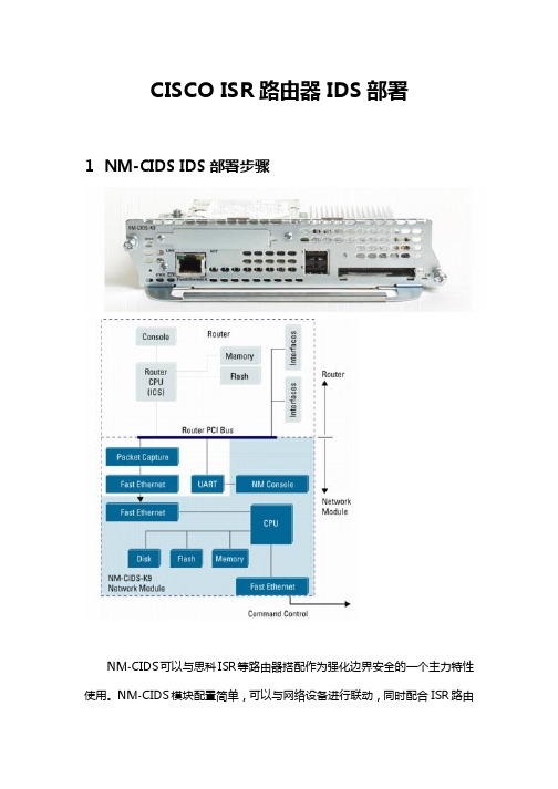
CISCO ISR路由器IDS部署1NM-CIDS IDS部署步骤NM-CIDS可以与思科ISR等路由器搭配作为强化边界安全的一个主力特性使用。
NM-CIDS模块配置简单,可以与网络设备进行联动,同时配合ISR路由器IOS IPS(目前IPS 650特征库)功能可以使设备识别攻击、拦截攻击的能力大幅度强化,同时利用NM-CIDS(目前1200+IPS 特征码支持)的信息发送给IPS网管软件IEV,以及思科安全网管MARS可以更加有效的帮助网络管理员在网络边界有效的隔离攻击时间,同时了解网络的威胁,如果结合ISR 路由器软件集成的NETFLOW功能配合MARS一起使用将会有更好的边界防御效果。
支持思科C2600, 2800, 3600, 3700, and 3800 全线路由器。
C2800, 3700, 3800 Up to 45 Mbps性能。
•Five hundred new TCP connections per second•Five hundred HTTP transactions per second1.1NM-CIDS 模式部署图例注意:NM-CIDS没有外部的Console接口,NM-CIDS模块上面的接口使提供网管操作使用的,例如更新软件、特征码库、监控信息传递、IDM及IEV等GUI界面网管访问使用。
注意此时:模块上面的管理接口可以连接至公司的网管VLAN,以便保证设备的安全性。
这点与其他IPS设备的网管接口连接方式完全类似。
1.2安装NM-CIDS首先,安装NM-CIDS进入ISR路由器槽位。
然后依次执行下面的命令完成对于模块的初始化安装工作。
1、首先通过命令确认你的模块是否安装完毕,并且获取模块所处相应槽位信息。
router # show interfaces ids-sensor slot_number/0请填写相应NM-CIDS所在槽位号。
可以利用Show run 命令观察所在槽位。
思科IPS产品线安装部署指南V2

思科IPS 设备配置部署简述目录1 概述 (3)2 IPS 4200典型工作模式 (4)2.1 IPS 4200 IDS 工作模式部署步骤 (6)2.1.1 IDS 4200 IDS模式部署图例 (6)2.1.2 配置IPS初始化安装 (6)2.1.3 配置业务承载交换机 (7)2.1.4 配置IDM访问 (8)2.1.5 配置IPS 4200软件升级 (11)2.1.6 配置IPS 4200接口采集信息 (15)2.1.7 配置IPS 4200与网络设备联动 (16)2.1.8 配置IPS 4200与网络设备联动策略执行 (19)2.1.9 观察IPS 4200联动效果 (22)2.1.10 使用IEV管理IPS 4200 (22)2.2 IPS 4200 IPS 工作模式部署步骤 (25)2.2.1 Inline 工作模式结构图 (25)2.2.2 Inline模式配置步骤 (26)3 NM-CIDS IDS部署步骤 (29)3.1 NM-CIDS 模式部署图例 (31)3.2 安装NM-CIDS (31)3.3 初始化配置NM-CIDS (32)3.4 配置IDM访问 (33)3.5 配置NM-CIDS软件升级 (34)3.6 配置NM-CIDS接口采集信息 (34)3.7 配置NM-CIDS与网络设备联动 (34)3.8 观察NM-CIDS联动效果 (34)4 IOS IPS部署步骤 (34)4.1 ISR IOS IPS模式部署图例 (35)4.2 ISR IOS IPS部署概述 (35)4.2.1 配置ISR路由器更新软件 (35)4.2.2 配置ISR路由器SDF文件 (35)4.2.3 配置ISR路由器启用IPS功能 (36)4.2.4 检查配置 (38)4.3 ASA/PIX IOS IPS部署概述 (40)4.3.1 配置ASA/PIX防火墙启用IPS功能 (40)4.3.2 检查配置 (41)5 ASA AIP IPS部署步骤 (42)5.1 配置AIP-IPS初始化安装 (42)5.2 配置ASDM 访问IPS (43)6 C6K IDSM部署步骤 (45)6.1 IDSM-2 Inline模式数据流图解 (46)6.2 确认IDSM-2 模块 (46)6.3 IDSM-2 模块和Catalyst 6500 关联配置 (48)6.4 IDSM-2 IPS 配置 (49)7 CSA 主机IPS/IDS部署步骤 (50)7.1 CSA 终端安全防护软件功能概述 (50)7.2 CSA 5.1 安装需求 (50)7.3 CSA 5.1 扩展功能总结 (50)7.3.1 禁止客户端卸载CSA、关闭CSA、停止CSA服务 (51)7.3.2 禁止客户端修改CSA安全级别 (55)7.3.3 管理可移动介质的使用:光驱、软驱、U盘 (57)8 IPS与MARS集成部署概要 (58)1 概述很多人在使用和配置IPS系列产品中遇到很多问题,甚至怀疑系列产品的功能及作用,其实这个产品的功能及特性勿庸置疑!只是如何利用好这个强大的产品真正的帮助最终用户解决问题才是目前的重点, 特此撰写一篇关于IPS实施部署指南的文章,供大家参加。
1.IPS安装和配置
IPS安装和配置(基于默认数据库)-Software version: SAP INFORMATION PLATFORM SERVICES 4.1 SP02 LINUX (64B)-Linux environment: RHELunix Server release 6.4Contents准备事项: (2)1.建用户和用户组 (2)2.在新建的用户的home目录的.bash_profile里添加如下语句 (2)3.确定用作IPS资料库的数据库,不同的数据库有不同的要求: (2)4.需要安装包含libstdc++.so.5的32 位库 (3)5.需要关闭SELinux: (3)6.确认是使用utf8字符: (4)7.确保linux的主机名不是默认的localhost (4)安装步骤: (4)正式安装: (4)安装过程中 (16)安装后 (16)卸载 ............................................................................................................................... 错误!未定义书签。
准备事项:1.建用户和用户组A dedicated unix user account should be created that owns all business objects files and sessions. Run the following commands as root to create user boe, a member of new unix group boe with a home directory /home/boe.$ groupadd -g 500 boe$ useradd -g boe -u 500 -d/home/boe$ chown boe:boe /home/boe2.在新建的用户的home目录的.bash_profile里添加如下语句(这些环境变量在安装好IPS及DS后,创建DS资源库时就开始要使用了)export LANG=en_US.utf8export LC_ALL=en_US.utf8if [ -f /home/boe/dataservices/DataDirect/odbc/odbc.sh ]; then. /home/boe/dataservices/DataDirect/odbc/odbc.shfiif [ -f /home/boe/dataservices/bin/al_env.sh ]; then. /home/boe/dataservices/bin/al_env.shfiLD_LIBRARY_PATH=$LD_LIBRARY_PATH:/home/boe/dataservices/binexport LD_LIBRARY_PATHexport BOE_REGISTRYHOME=/home/boe/sap_bobj/data/.bobj/registryexport LINK_DIR=/home/boe/dataservices3.确定用作IPS资料库的数据库,不同的数据库有不同的要求:DB2数据库1).DB2 需要满足以下两个条件:user's home directory must have minimum mode of 755these directories cannot exist: ~/sqllib and ~/$USER(可用chmod 755 –R pathname 来改变该目录及所有子目录的权限)2). 另外需满足DB2对于user id和user group的要求。
思科通用AP规定域部署指南说明书

Universal AP Regulatory Domain Deployment GuideUniversal AP Regulatory Domain Deployment Guide2System Requirements2Universal Domain AP2Associating Universal AP to WLC3Configuring the WLAN4Priming UX AP Through AirProvision App(Manual Identification)5Installing AirProvision Application6Configuring Universal AP Through Airprovision App6Automatic Identification10Summary12Revised: September 15, 2016,Universal AP Regulatory Domain Deployment GuideSystem RequirementsWLCs Supported with Code8.0.MR and8.1WLC2500,WLC5500,WiSM2,WLC7500,WLC8500Access Points SupportedThe following access points are supported with universal SKUs UXK9.AP702W/AP702I,AP1602,AP2602,AP2702,AP3602*,AP3702,and AP1532.*The11ac Module with–UX is also supported for AP3600.All other AP models that are not listed above will NOT support Universal PIDs.Universal Domain APThe aim of introducing Universal SKU AP is to address the worldwide regulatory compliance requirement based on geo-location of the Cisco Wireless Access Points(APs).Solution will collapse all current regulatory domains into a single SKU APs.This will be applicable only to newer-UX PIDs introduced and will not affect the existing APs that are preconfigured with a specific regulatory configuration.Universal AP can be configured to correct the regulatory domain in two phases:•Manual Identification(Through Cisco AirProvision App)•Automatic Identification(Through NDP propagation)2Manual IdentificationThe manual identification process involves the following tasks:•Smart Phone based solution (Cisco AirProvision App)communicates with the Universal AP on a secure channel (2.4GHz only).•For new installations,the user needs to prime at least one AP in the RF neighborhood by manual identification method.•APs primed at a different country/reg.domain rely on manual identification to automatically correct country configuration.•Upon failure of automatic identification,the Universal AP retracts to manual identification.Automatic IdentificationThe automatic identification process involves the following tasks:•The process relies on Cisco Infrastructure to identify and apply reg.domain and country configurations.•Cisco proprietary Neighbor Discovery mechanism identifies secure Cisco Universal APs in the RF neighborhood.•Universal AP learns domain configurations from the adjacent neighbor ’s 802.11beacons frame and filters the invalid and malicious rogues.•Adjacent Universal APs have NDP propagation flag set that will be used to propagate valid country and reg.domain to the rest of the APs.Associating Universal AP to WLCUniversal AP does not require any particular configurations on Wireless LAN Controller (WLC)to allow Universal AP to associate.Connect the universal SKU AP to the WLC.Once the AP has joined the controller and downloaded the code,you can check the AP model and SKU by going to the WIRELESS tab from the WLC main menubar.You will see the APs LED blinking red and green even though the AP has obtained the IP address andjoined the controller.This is because there is no regulatory domain set on the AP,and it has not beenprimed with the correct domain.Note To check if the AP is not already primed for a specific country domain,click the AP Name,and under Advanced tab,the ‘Regulatory Domains ’shows –UX for both radios.Note that the ‘Country Code ’also shows ‘UX ’because the AP is not primed with the correct country domain.3You can configure multiple country domains on the WLC as well for AP join.As it is a universal SKUNoteAP(-UXK9),it should join the WLC regardless of the country domain set on the WLC.Configuring the WLANTo configure a WLAN through which an administrator can prime the AP to a correct regulatory domain,perform the following steps: 1Go to WLAN>Advanced.2Scroll down to the Universal Admin Support area,and check the Universal Admin check box to enable it.3Click Apply.4Make sure that the WLAN has the security set to PSK or 802.1x as open authentication WLAN will notallow universal admin support.Note The universal admin enabled WLAN used for priming the AP should be able to reach the managementIP of the controller.Similarly,for Autonomous AP,the universal admin enabled WLAN should be ableto reach the Autonomous AP's management IP address.Note Priming UX AP Through AirProvision App (Manual Identification)This method uses an AirProvision application on smartphone that runs on different flavors of mobile OS.Upon successful authentication,the smartphone communicates with the Universal AP on a secure 2.4GHz channel.The smartphone then requests the AP configurations to differentiate Universal SKU AP from other access points.When the associated access point is identified as Universal AP,the smartphone pushes the regulatory configurations to the AP.When a user wants to prime a universal AP,the user needs to access the AirProvision app with CCO credentials.Without proper authentication,the AirProvision app will not be able to configure the access point.After successful authentication,the smartphone associates to Universal AP over a secure 2.4GHz channel as a client.Prior to the association with AP,the AirProvision app also gathers its location information from the inbuilt GPS and cell tower that advertise country information by extracting Mobile Country Code (MCC)Identifier from the Public LAN Mobile Network (PLMN).Once associated,Universal AP sends information about its AP type,Reg.Domain,and country configurations to distinguish from existing Cisco APs and to ensure that it has been primed already.For an unprimed/out of box Universal AP,the AirProvision app configures the AP with correct reg.domain that will derive base on the AP information and country code details via GPS and MCC ID.The AirProvision app maintains a database that maps country configurations to regulatory domain for a specific AP model.This information is sent to Universal AP to migrate it into correct Reg.Domain and country configurations.Modes of AvailabilitiesManual Identification works only on the following modes of unified APs:•Local•FlexConnect•Bridge*•Autonomous APs*Unified APs in Bridge mode require wired connection to WLAN Controller for initial AP deployment.In the absence of Universal Root AP (RAP),Universal Mesh AP will not allow domain conversion.Following modes of Unified APs will NOT be able to leverage Manual Identification method:•Monitor•Sniffer•Rogue-Detector•SE Connect5The AirProvision app supports the following two modes of operations:•Configure Mode—This is the default mode of operation for the AirProvision app to configure Universal SKU AP.Fresh out of box APs are configured via configure knob when associated AP is configured with Universal Attributes(Reg.Domain:-UX, Country:UX).•Audit Mode—This special mode handles the misconfigured primed Universal APs,when the Universal APs are shipped via tier-2distributors or were misconfigured due to change in location.In such cases,the reg.domain configurations are corrected via the AirProvision app in audit mode.The audit mode can overwrite the reg.domain configurations of an already primed Universal AP.Installing AirProvision ApplicationThe AirProvision application,to migrate Universal AP into correct regulatory domain,is supported on following versions of SmartPhone Operating Systems:•Android Jelly Bean4.3or higher•Apple iOS7.0or higher•Windows Mobile OS8.0Depending on your smartphone's platform,download and install the Cisco AirProvision application from iOS App Store,Google Play Store,or Windows Phone Store.Configuring Universal AP Through Airprovision AppTo configure the Universal AP through AirProvision app,perform the following steps:ProcedureStep 1Connect the client(iPhone or Android phone)to the universal admin enabled SSID.(In this setup,it is POD6-PSK).Ensure that the client associates to the AP on2.4GHz radio.Step 2Open the Airprovision app.Log in to the app using your CCO credentials.Also,enable location services for the app.6When the location service is enabled,the Universal AP login screen appears.The username and password appears asdefault in the login screen.(The default User name is'Cisco'and Password is'Cisco',and are case sensitive).If the admin has configured a specific username/password then enter admin configured username/password.Step 3Click Log In.The AP configuration page appears,where you can see the Configure and Audit tabs.The status of the Universal AP can be seen by clicking these tabs.Currently,the AP is not provisioned,so it states the following under configure and Audit tabs:•AP Provision=No•2.4GHz=-UX7•5GHz=-UX•Configured Country=UXStep 4Click Configure.Step 5The AP reboots and joins back with the regulatory domain it received through the GPS/Location services.You can check this by navigating to the WIRELESS>AP Name>Advanced tabs.The Regulatory Domains is changed from–UX to –A,which is the correct regulatory domain.The country code also shows US.As the AP is primed through the app,the Universal Prime status shows as Web App.8Once the AP is primed,all the radios are configured to the correct domain.This holds true for11ac module as Notewell.Also,you can insure this by connecting the client(iPhone or Android phone)to the universal admin enabled SSID (POD6-PSK in this setup).Then,log in to the AirProvision app to see that the Universal AP is configured correctly as follow:•AP Provision=Yes•2.4GHz=-A•5GHz=-A•Configured Country=USIn an Android phone,the AirProvision app behaves little different.That is,once you open the Airprovision app,it asks for CCO credentials to connect to the universal admin enabled SSID from the list of discovered SSIDs.Once you connect to the SSID,the procedure is same as iPhone.9Noteto the rest of the Universal domain APs on the network in the same RF neighborhood.This process is also knownas Automatic Identification.Automatic IdentificationAutomatic Identification method solely relies on Cisco’s RF intelligence to propagate the new reg.domain and country configurations to the local RF neighborhood.Cisco proprietary Neighbor Discovery Protocol(NDP)frames are leveraged to discover secure Cisco10Universal APs in the network and propagate reg.domain attributes to the localized RF neighborhood.The following UX-AP is primed to correct regulatory domain through automatic identification.Automatic identification through NDP is only valid among the–UX PIDs APs.NoteAutomatic Identification method is the default method used by Cisco Universal APs.While manual identification helps to migrate Universal AP into correct reg.domain,automatic identification propagates reg.domain configuration to the localized RF neighborhood quickly and efficiently.The automatic identification method requires dependencies on presence of existing Cisco Universal APs in the network.Therefore,for initial seed AP or when APs are installed in disjoint RF neighborhood,the user needs to prime at least one Universal AP in the network.The automatic identification method also helps to autocorrect already primed Universal AP;this will be addressed by special notification via NDP that can override other Universal APs configurations.Limited Support on Autonomous APsCurrent framework is designed to work on both Unified and Autonomous APs.However,Phase1of this project does not include Automatic Identification(through NDP)support for Autonomous APs.It will be deferred to future8.x SW release.Automatic Identification on a Mesh NetworkAccess points operating in Bridge mode can be provisioned over the air using the Automatic Identification process.Both Bridge mode Root Access Points(RAPs)and Mesh Access Points(MAPs)use over the air2.4GHz NDP packets to determine the local regulatory domain.The list of supported5GHz channels differ based on regulatory domain,so no packets are transmitted across the 5GHz radios until the access point is provisioned.11RAP sends NDP messages on all2.4GHz channels to adjacent MAPs.All MAPs that can hear the message will be provisioned to match the same regulatory domain as the RAP.Once provisioned,the Bridge mode access points will re-join the RAP and form a mesh tree.SummaryTo summarize,this deployment guide covers the following:•Combines intelligence from trusted Cisco Neighbor Discovery Messages along with Smart Phone based audit scheme(App).•Solution works for customers with no Cisco APs in prior deployments.•Expedites domain identification process from existing RF neighbors to bring faster network convergence.•Reliable solution for worldwide distributors where APs are shipped to one location and then get distributed to end customers.•Covers boundary conditions when APs are primed in a different regulatory domain/country.•Encompasses safety net for deployments where initial seed or majority of existing APs are configured with incorrect country/ reg.domain configurations.12©2015Cisco Systems,Inc.All rights reserved.Europe Headquarters Asia Pacific Headquarters Americas HeadquartersCisco Systems International BV Amsterdam, The NetherlandsCisco Systems (USA) Pte. Ltd.Singapore Cisco Systems, Inc.San Jose, CA 95134-1706USA Cisco has more than 200offices worldwide.Addresses,phone numbers,and fax numbers are listed on theCisco Website at /go/offices.。
思科安全数据中心集成下一代IPS威胁管理设计指南说明书

面向企业的安全数据中心 -集成下一代 IPS 的威胁管理设计指南 - 最后更新日期:2015 年 4 月 24 日作者简介Tom HogueMike StormBart McGlothinMatt Kaneko作者简介Tom Hogue ,思科安全业务部门安全解决方案经理T om 是思科数据中心安全解决方案经理,他在加入思科之前便从事集成解决方案的开发,目前已有 20 年以上的行业经验。
许多行业领先数据中心解决方案(例如 FlexPod 、Vblock 和安全多租户)的开发工作都是在 T om 的领导下进行的。
他目前负责领导为面向企业的安全数据中心解决方案产品组合开发解决方案,是“Single Site Clustering with TrustSec Cisco Validated Design Guide”(采用 TrustSec 的单站点集群思科验证设计指南)的作者之一。
Mike Storm , 思科安全业务部门高级技术工程主管 CCIE 安全(编号 13847)Mike 负责领导思科系统公司全球安全社区研究竞争架构,并提出见解。
他的主要研究课题之一是数据中心安全性;此外,他还从事于为企业组织开发注重将下一代安全服务与数据中心和虚拟化技术紧密集成的架构。
Storm 在网络和网络安全行业有 20 多年经验,拥有业务顾问、技术作家,以及网络和网络安全主题职业演讲家等诸多身份。
Storm 是多篇相关文章(包括“Secure Data Center Design Field Guide”[安全数据中心设计现场工作指南])的作者,也是“Single Site Clustering with TrustSec Cisco Validated Design Guide”(采用 TrustSec 的单站点集群思科验证设计指南)的作者之一。
Bart McGlothin ,思科安全业务部门安全系统架构师Bart 是一位思科安全解决方案架构师,在行业解决方案领域有超过 15 年经验。
思科Firepower NGIPSv快速入门指南说明书

适用于 VMware 部署的思科 Firepower NGIPSv 快速入门指南修订日期:2018 年 10 月 7 日您可以使用 VMware 部署适用于 VMware 的思科 Firepower NGIPSv。
有关具体系统要求和支持的虚拟机监控程序,请参阅思科 Firepower 兼容性指南。
⏹Firepower NGIPSv 的 VMware 功能支持,第 1 页⏹Firepower NGIPSv 和 VMware 的先决条件,第 2 页⏹系统要求,第 3 页⏹适用于 Firepower NGIPSv 和 VMware 的准则和限制,第 4 页⏹使用 vMotion 的原则,第 5 页⏹OVF 文件准则,第 5 页⏹使用 VMware vSphere Web 客户端或 vSphere 虚拟机监控程序部署 Firepower NGIPSv,第 6 页⏹安装后配置,第 7 页⏹使用 CLI 设置 Firepower NGIPSv,第 9 页⏹将 Firepower NGIPSv 注册至 Firepower 管理中心,第 11 页Firepower NGIPSv 的 VMware 功能支持下表列出了Firepower NGIPSv 支持的 VMware 功能。
表1Firepower NGIPSv 的 VMware 功能支持特性说明支持(是/否)备注冷克隆VM 在克隆过程中关闭。
否-vMotion用于实时迁移 VM。
是使用共享存储。
请参阅使用 vMotion 的原则,第 5 页。
在添加过程中运行。
否-热添加 VM热克隆VM 在克隆过程中运行。
否—在删除过程中运行。
否-热删除 VM快照VM 会冻结几秒钟。
否-暂停和恢复VM 暂停,然后恢复。
是—vCloud Director允许自动部署 VM。
否-VMware FT用于 VM 上的 HA。
否-思科系统公司适用于 VMware 部署的思科 Firepower NGIPSv 快速入门指南 Firepower NGIPSv 和 VMware 的先决条件Firepower NGIPSv 和 VMware 的先决条件您可以使用 VMware vSphere Web 客户端或 vSphere 独立客户端在 ESXi 上部署 Firepower NGIPSv 。
思科电源配件安装和管理指南说明书

思科电源配件SB-PWR-12V SB-PWR-INJ1安装和管理指南Cisco 和 Cisco 徽标是思科和/或其附属公司在美国和其他国家/地区的商标或注册商标。
若要查看思科的商标列表,请访问此URL:/go/trademarks。
文中提及的第三方商标为其相应所有人的财产。
使用“合作伙伴”一词并不暗示思科和任何其他公司之间存在合伙关系。
(1110R)目录第 1 章: 电源配件安装2产品概览2设备开箱3附加要求3安装电源适配器3安装 PoE 馈电器4PoE 馈电器规格6附录 A: 快速索引71电源配件安装本手册介绍了如何安装和管理电源适配器及以太网供电 (PoE) 馈电器。
产品概览本指南中的配件概览:•SB-PWR-12V 电源适配器 - 一种 12V 1A 桌面式电源适配器。
该电源适配器是一款专为 Cisco WAP321 无线接入点而设计的外接电源适配器。
当不使用 PoE 时,可用它来为系统提供直流电力。
该款电源适配器可以用于其他思科产品。
•SB-PWR-INJ1 以太网供电 (PoE) 馈电器 - 一种内联单端口千兆 802.3af PoE 馈电器。
该 PoE 馈电器与非 PoE 上游交换机端口连接时,可用来为无线接入点或 IP 电话等下游设备提供直流电力。
该 PoE 馈电器具有两个以太网端口。
一个端口用来连接非 PoE 上游设备,如路由器或交换机。
另一端口是供电端口,用来连接支持 PoE 功能的下游设备。
设备开箱电源适配器包装箱内含:•SB-PWR-12V 电源适配器•电源线•指针卡PoE 馈电器包装箱内含:•SB-PWR-INJ1 PoE 馈电器•电源线•指针卡附加要求配备两条直通 5 类以太网电缆,将 PoE 馈电器与网络、接入点或网桥连接。
如果将接入点或网桥安装在吊顶之类的空间,请查阅国家和地方安全规范,确保用来连接装置的以太网电缆符合适用的标准。
安装电源适配器步骤 1将电源线与电源适配器相连。
Cisco IPSec VPN 配置详解【范本模板】
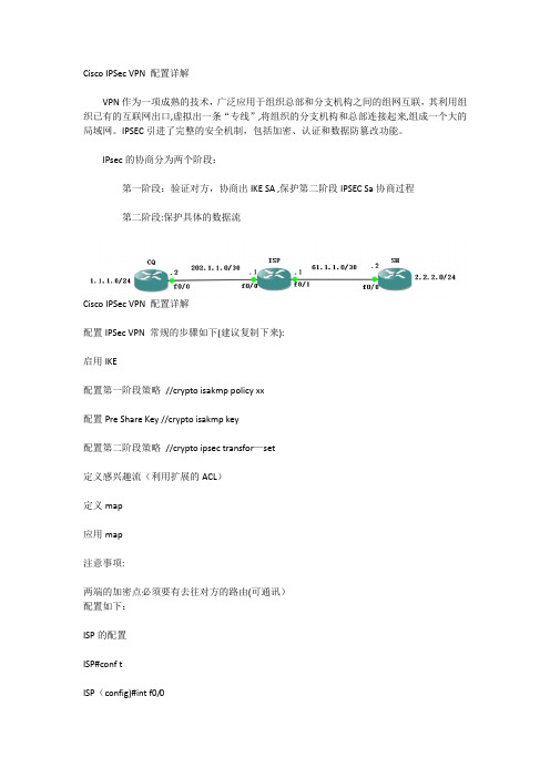
Cisco IPSec VPN 配置详解VPN作为一项成熟的技术,广泛应用于组织总部和分支机构之间的组网互联,其利用组织已有的互联网出口,虚拟出一条“专线”,将组织的分支机构和总部连接起来,组成一个大的局域网。
IPSEC引进了完整的安全机制,包括加密、认证和数据防篡改功能。
IPsec的协商分为两个阶段:第一阶段:验证对方,协商出IKE SA ,保护第二阶段IPSEC Sa协商过程第二阶段:保护具体的数据流Cisco IPSec VPN 配置详解配置IPSec VPN 常规的步骤如下(建议复制下来):启用IKE配置第一阶段策略//crypto isakmp policy xx配置Pre Share Key //crypto isakmp key配置第二阶段策略//crypto ipsec transfor—set定义感兴趣流(利用扩展的ACL)定义map应用map注意事项:两端的加密点必须要有去往对方的路由(可通讯)配置如下:ISP的配置ISP#conf tISP(config)#int f0/0ISP(config—if)#ip add 202.1。
1。
1 255.255.255.252ISP(config-if)#no shISP(config—if)#int f0/1ISP(config—if)#ip add 61.1。
1.1 255.255。
255.252ISP(config-if)#no shCQ(左边路由器)的配置:CQ#conf tCQ(config)#int f0/0CQ(config-if)#ip add 202.1。
1.2 255。
255.255.252CQ(config-if)#no shCQ(config-if)#int lo 0CQ(config-if)#ip add 1.1.1。
1 255。
255.255。
0CQ(config-if)#no shCQ(config-if)#exitCQ(config)#ip route 0。
CISCO产品配置手册

CISCO路由器产品配置手册第一章路由器配置基础.............................一、基本设置方式 .............................二、命令状态 (3)三、设置对话过程 .............................四、常用命令 .................................五、配置IP寻址 ..............................六、配置静态路由 .............................第二章广域网协议设置.............................一、HDLC .....................................PPP ....................... 错误!未定义书签。
X.25 .........................................Frame Relay ..................................ISDN .........................................PSTN .........................................第三章路由协议设置...............................RIP协议......................................IGRP协议.....................................OSPF协议.....................................重新分配路由 .................................IPX协议设置.................................. 第四章服务质量及访问控制.........................协议优先级设置 ...............................队列定制 .....................................访问控制 ..................................... 第五章虚拟局域网(VLAN)路由.....................虚拟局域网(VLAN) .............................交换机间链路(ISL)协议 ......................虚拟局域网(VLAN)路由实例错误!未定义书签。
图解思科路由器配置教程

cisco路由器配置教程手把手教你配置cisco路由器经过几十年的发展,从最初的只有四个节点的ARPANET发展到现今无处不在的Internet,计算机网络已经深入到了我们生活当中。
随着计算机网络规模的爆炸性增长,作为连接设备的路由器也变得更加重要。
公司在构建网络时,如何对路由器进行合理的配置管理成为网络管理者的重要任务之一。
本专题就为读者从最简单的配置开始为大家介绍如何配置cisco路由器。
很多读者都对路由器的概念非常模糊,其实在很多文献中都提到,路由器就是一种具有多个网络接口的计算机。
这种特殊的计算机内部也有CPU、内存、系统总线、输入输出接口等等和PC相似的硬件,只不过它所提供的功能与普通计算机不同而已。
和普通计算机一样,路由器也需要一个软件操作系统,在cisco路由器中,这个操作系统叫做互联网络操作系统,这就是我们最常听到的IOS软件了。
下面就请读者跟着我们来一步步的学习最基本的路由器配置方法。
cisco路由器基本配置:√ cisco IOS软件简介:大家其实没必要把路由器想的那么复杂,其实路由器就是一个具有多个端口的计算机,只不过它在网络中起到的作用与一般的PC不同而已。
和普通计算机一样,路由器也需要一个操作系统,cisco把这个操作系统叫作cisco互联网络操作系统,也就是我们知道的IOS,所有cisco路由器的IOS都是一个嵌入式软件体系结构。
cisco IOS软件提供以下网络服务:基本的路由和交换功能。
可靠和安全的访问网络资源。
可扩展的网络结构。
cisco命令行界面(CLI)用一个分等级的结构,这个结构需要在不同的模式下来完成特定的任务。
例如配置一个路由器的接口,用户就必须进入到路由器的接口配置模式下,所有的配置都只会应用到这个接口上。
每一个不同的配置模式都会有特定的命令提示符。
EXEC为IOS软件提供一个命令解释服务,当每一个命令键入后EXEC 便会执行该命令。
√第一次配置Cisco路由器:在第一次配置cisco路由器的时候,我们需要从console端口来进行配置。
- 1、下载文档前请自行甄别文档内容的完整性,平台不提供额外的编辑、内容补充、找答案等附加服务。
- 2、"仅部分预览"的文档,不可在线预览部分如存在完整性等问题,可反馈申请退款(可完整预览的文档不适用该条件!)。
- 3、如文档侵犯您的权益,请联系客服反馈,我们会尽快为您处理(人工客服工作时间:9:00-18:30)。
此案例配置共分7步:
第一步:配置vpdn
vpdn enable(启用路由器的虚拟专用拨号网络---vpnd)
vpdn-group office(建立一个vpdn组,)
request-dialin(初始化一个vpnd tunnel,建立一个请求拨入的vpdn子组,)
protocol pppoe(vpdn子组使用pppoe建立会话隧道)
第二步: 配置路由器连接adsl modem的接口
interface Ethernet1
no ip address
pppoe enable允许以太接口运行pppoe
pppoe-client dial-pool-number 1将以太接口的pppoe拨号客户端加入拨号池1
第三步:配置逻辑拨号接口:
interface Dialer1
ip address negotiated从adsl服务商动态协商得到ip地址
ip nat outside为该接口启用NA T
encapsulation ppp为该接口封装ppp协议
dialer pool 1该接口使用1号拨号池进行拨号
dialer-group 1该命令对于pppoe是意义不大的
ppp authentication pap callin启用ppp pap验证
ppp pap sent-username xxxxxxx password 0 yyyyyyy使用已经申请的用户名和口令第四步:配置内部网络接口
interface Ethernet0(内部网络接口)
ip address 10.1.1.1 255.255.255.0
ip nat inside为该接口启用NA T
第五步:配置路由器为内部网络主机提供dhcp服务
ip dhcp excluded-address 10.1.1.1
ip dhcp pool ABC
import all(导入dns和wins server)
network 10.1.1.0 255.255.255.0
default-router 10.1.1.1
第六步:配置NA T:
access-list 1 permit 10.1.1.0 0.0.0.255
ip nat inside source list 1 interface Dialer1 overload
第七步:配置缺省路由
ip route 0.0.0.0 0.0.0.0 Dialer1
vpdn enable
!
vpdn-group pppoe
request-dialin
protocol pppoe
!
interface Ethernet0/0
no ip address
full-duplex
pppoe enable
pppoe-client dial-pool-number 1
!
interface Ethernet0 /1
ip address 10.0.0.254 255.255.255.0
ip nat inside
ip tcp adjust-mss 1452
full-duplex
no cdp enable
!
interface Dialer1
mtu 1492
ip address negotiated
ip nat outside
encapsulation ppp
dialer pool 1
dialer-group 2
no cdp enable
ppp authentication pap callin
ppp pap sent-username fmapdof password 0 f535120
!
ip nat inside source list 1 interface Dialer1 overload
no ip http server
ip classless
ip route 0.0.0.0 0.0.0.0 Dialer1 permanent
!
access-list 1 permit any
dialer-list 2 protocol ip permit
=================
需要注意的就是 ip tcp adjust-mss 1452 调整tcp最大分段大小以满足PPPOE 下的MTU
因为pppoe下实际的数据段只能为1500-8(ppp的头)=1492,1492再减去TCP和IP头各20等于1452,也就是说为了避免2层上不停的分割数据包,适应某些应用如MSN,同时加快传输.。
