Ametek 直流电源产品ATE
ATE设备与技术

自动测试设备(ATE)发展状况在目前的ATE设备厂商中,有名的供应商有:爱德万(Advantest)、泰瑞达(Teradyne)、安捷伦(Agilent)和横河(Yokogawa)恩普科技(NPTest)、科利登(Credence)等,现在科利登已收购恩普科技。
现在这些ATE公司的产品平台不同,编程语言也不同。
同一家公司在产品升级换代时也可能有很大的变化。
在产品上市时间逐渐缩短时,用户却要花更多时间重新学习和熟悉新的测试系统,这不是市场发展的规律。
为了降低研发费用和设备成本,同时加快客户的测试周期,各大公司都在探索着各种不同的技术路线和架构。
Credence认为Sapphire系统将是未来ATE的主导技术之一,“Sapphire是一种全新的概念,系统的每个板有32个槽,可通过板的调整实现单一系统测试从少管脚产品到多管脚,速度从200M、400M、800M到1600M的测试。
”Credence 正是希望通过这一架构降低SOC测试的门槛,同时由于产品升级时不需要更换平台,将会降低用户未来的成本。
与用户共建行业标准也是一条技术路线。
其中半导体测试联盟(STC)为ATE设计的Openstar 开放式架构就受到了Advantest、Intel和Motorola等厂商的支持。
而这一行业组织的目的也是为了产品的标准化,使厂商能够为测试设备开发“即插即用”模块,降低IC测试成本。
Advantest的SOC测试系统T2000是基于Openstar架构的第一台测试系统,它已在测试市场赢得了多项定单。
Teradyne的OpenFLEX平台对架构的概念有不同的定义。
允许第三方在Teradyne的平台上建立自己的产品。
IC设计者和制造者都是半导体ATE的用户,虽然设计者的用量少,可能一家公司只需拥有一台,但成熟的设计一旦量产,就可能对测试有大量的需求,而促使制造者的大量购买。
从中国的现状考虑,中国先进的fabs和封测厂的主导业务仍为对外代工,因此服务好制造企业的客户仍然是一些ATE公司的主要工作,而针对fabless公司的服务主要是着眼于未来市场。
ATA系列自动电源转换装置产品介绍说明书

ATA系列自动电源转换装置出众的整体解决方案 ATA—执行机构IZM9系列ATA 系列自动电源转换装置ATA 系列自动电源转换装置ATA 系列概述 ...................................................................................4型号说明 ...............................................................................5主要技术数据及性能指标 .................................................................6控制器 .................................................................................7电气线缆 ..............................................................................16执行断路器IZM9系列型号说明 ..............................................................................17脱扣器技术参数 ........................................................................18系统概览 ..............................................................................19可选附件 ..............................................................................23外形及安装尺寸 ........................................................................24系统电气图 ............................................................................48选型与订货 ............................................................................69订购指南 (73)ATA 系列执行断路器IZM9系列目录3ATA系列自动电源转换装置概述ATA系列产品描述伊顿的ATA系列自动转换开关装置,满足额定电压AC400V以下电源的自动转换。
程控电源品牌有哪些_程控电源品牌汇总
程控电源品牌有哪些_程控电源品牌汇总程控电源品牌汇总——美国AMETEKAmetek阿美特克可编程电源事业部总部位于加利福利亚州的圣地亚哥,它是一家全球领先的精密、可编程电源及电子负载设计与生产厂家,其产品广泛应用于多个式业领域的研发、自动测试设备(ATE)、过程控制、电源总线模拟及电源调节方面。
阿美特克可编程电源事业部是阿美特克有限公司的下属部门,它于收购CaliforniaInstruments公司及Xantrex公司的可编程电源部门后成立。
阿美特克是一家全球领先的电子仪器和机电装置制造商,其年销售额超过25亿美元。
程控电源品牌汇总——韩国ODAODA是一家以测试电源和电子负载为主要开发仪器的韩国开发商,在全球范围内广泛提供贴牌生产和贴牌设计的可编程DC电源和负载,并提供电源老化系统,LED老化系统,产品的寿命也十分乐观。
程控电源品牌汇总——安捷伦安捷伦科技有限公司是一家多元化的高科技跨国公司,它于1999年从惠普研发有限合伙公司中分离出来,主要致力于通讯和生命科学两个领域内产品的研制开发、生产销售和技术服务等工作。
安捷伦的化学分析业务主要提供气相色谱,气相色谱-单四级杆质谱、串联四级杆质谱、四级杆飞行时间质谱等高端设备,2009年收购瓦里安后,安捷伦整合了光谱产品线与化学分析业务及其真空设备,并在无机领域中提供ICP,ICP-MS等产品,目前ICP-MS销量全球第一。
程控电源品牌汇总——明纬海明纬电子实业有限公司是一家集设计开发、生产、贸易于一体的高科技开关电源制造商。
生产的开关电源具有质优价廉、性能稳定,安全可靠,使用寿命长等特点,广泛应用于工控自动化领域、LED显示屏、通讯、仪器仪表等行业,是取代传统控制变压器的理想升级换代产品。
公司的产品设计符合美国ULl012、德国TUVEN60950,欧共体EMCLVD、IEC950、VL1950。
艾特顿199031电源速调器说明书

Eaton 199031Eaton Moeller® series Rapid Link - Speed controllers, 8.5 A, 4 kW, Sensor input 4, Actuator output 2, 400/480 V AC, PROFINET, HAN Q4/2, with fanAllgemeine spezifikationEaton Moeller® series Rapid Link Speed controller199031195 mm270 mm 220 mm 3.64 kgIEC/EN 61800-5-1 UL approval CE RoHS UL 61800-5-14015081970896RASP5-8424PNT-4120001S1Product NameCatalog NumberProduct Length/Depth Product Height Product Width Product Weight Certifications Catalog Notes EANModel Code3 fixed speeds and 1 potentiometer speedcan be switched over from U/f to (vector) speed control Connection of supply voltage via adapter cable on round or flexible busbar junction480 VIs the panel builder's responsibility. The specifications for the switchgear must be observed.400 V AC, 3-phase480 V AC, 3-phaseMeets the product standard's requirements.4 kW500 VMeets the product standard's requirements.-40 °C380 VIGBT inverterKey switch position OFF/RESETControl unitInternal DC linkKey switch position AUTOKey switch position HANDPTC thermistor monitoringThermo-click with safe isolationPC connectionSelector switch (Positions: REV - OFF - FWD)FanTwo sensor inputs through M12 sockets (max. 150 mA) for quick stop and interlocked manual operation2 Actuator outputs0 Hz200 %, IH, max. starting current (High Overload), For 2 seconds Generation Change RA-SP to RASP5Elektromagnetische Verträglichkeit (EMV)Generationentausch RAMO4 zu RAMO5Generationswechsel RASP4 zu RASP5Generation Change RASP4 to RASP5Firmware Update RASP 4.0Anschluss von Frequenzumrichtern an Generatornetze Generationentausch RA-SP zu RASP4.0Generationenwechsel RA-SP zu RASP5Generation change from RA-MO to RAMO 4.0Configuration to Rockwell PLC Rapid Link 5 Generationentausch RA-MO zu RAMO4.0Configuration to Rockwell PLC for Rapid LinkGeneration change RAMO4 to RAMO5Generation change from RA-SP to RASP 4.0MN034004_DEMN040003_DERapid Link 5 - brochureDA-SW-USB Driver DX-COM-STICK3-KITDA-SW-Driver DX-CBL-PC-3M0DA-SW-drivesConnectDA-SW-drivesConnect - installation helpDA-SW-drivesConnect - InstallationshilfeDA-SW-USB Driver PC Cable DX-CBL-PC-1M5Material handling applications - airports, warehouses and intra-logistics ETN.RASP5-8424PNT-4120001S1.edzIL034093ZUDE | Rapid Link 5Sortimentskatalog Antriebstechnik-DEMains voltage - max10.11 Short-circuit ratingRated operational voltage10.4 Clearances and creepage distancesOutput at quadratic load at rated output voltage - max Output voltage - max10.2.3.1 Verification of thermal stability of enclosures Ambient storage temperature - minMains voltage - minFitted with:Output frequency - minStarting current - max Anmerkungen zur AnwendungBenutzerhandbücherBroschüreneCAD model Installationsanleitung InstallationsvideosKatalogeevery 20 seconds, Power section10 kA40 °CPROFINET, optional5 HP500 Hz8 kHz, 4 - 32 kHz adjustable, fPWM, Power section, Main circuitParameterization: drivesConnectParameterization: FieldbusInternal and on heat sink, temperature-controlled Fan Parameterization: drivesConnect mobile (App) Parameterization: Keypad-10 °C≤ 0.6 A (max. 6 A for 120 ms), Actuator for external motor brakeDoes not apply, since the entire switchgear needs to be evaluated.8.5 ADoes not apply, since the entire switchgear needs to be evaluated.Does not apply, since the entire switchgear needs to be evaluated.Speed controller ramo5_v36.dwgrasp5_v36.stpeaton-bus-adapter-rapidlink-speed-controller-dimensions.eps eaton-bus-adapter-rapidlink-speed-controller-dimensions-003.eps eaton-bus-adapter-rapidlink-speed-controller-dimensions-002.eps eaton-bus-adapter-rapidlink-speed-controller-dimensions-004.epsRated conditional short-circuit current (Iq)Ambient operating temperature - maxCommunication interfaceAssigned motor power at 115/120 V, 60 Hz, 1-phase Output frequency - maxSwitching frequencyFeaturesAmbient operating temperature - minBraking currentNumber of HW-interfaces (serial TTY)10.6 Incorporation of switching devices and components Nominal output current I2N10.2.6 Mechanical impact10.3 Degree of protection of assembliesProduct category mCAD model ZeichnungenRadio interference classC1: for conducted emissions onlyC2, C3: depending on the motor cable length, the connected load, and ambient conditions. External radio interference suppression filters (optional) may be necessary.Heat dissipation capacity Pdiss0 WRated control voltage (Uc)24 V DC (-15 %/+20 %, external via AS-Interface® plug) 400/480 V AC (external brake 50/60 Hz)Assigned motor power at 460/480 V, 60 Hz, 3-phase5 HPNumber of HW-interfaces (RS-422)Mains current distortion120 %ProtocolPROFINET IO10.9.2 Power-frequency electric strengthIs the panel builder's responsibility.Overvoltage categoryIIIDegree of protectionNEMA 12IP65Ambient storage temperature - max70 °CRated impulse withstand voltage (Uimp)2000 VConnectionPlug type: HAN Q4/2Overload currentAt 40 °CFor 60 s every 600 sFunctionsFor actuation of motors with mechanical brake3 fixed speeds1 potentiometer speedOutput at linear load at rated output voltage - max4 kWMains voltage tolerance380 - 480 V (-10 %/+10 %, at 50/60 Hz)Leakage current at ground IPE - max3.5 mAConverter typeU converter10.2.2 Corrosion resistanceMeets the product standard's requirements.Supply frequency50/60 Hz10.2.4 Resistance to ultra-violet (UV) radiationMeets the product standard's requirements.10.2.7 InscriptionsMeets the product standard's requirements.Shock resistance15 g, Mechanical, According to IEC/EN 60068-2-27, 11 ms, Half-sinusoidal shock 11 ms, 1000 shocks per shaftApplication in domestic and commercial area permittedYesNumber of inputs (analog)Number of phases (output)310.12 Electromagnetic compatibilityIs the panel builder's responsibility. The specifications for the switchgear must be observed.10.2.5 LiftingDoes not apply, since the entire switchgear needs to be evaluated.Number of HW-interfaces (RS-485)1Number of HW-interfaces (industrial ethernet)Efficiency98 % (η)System configuration typeCenter-point earthed star network (TN-S network)AC voltagePhase-earthed AC supply systems are not permitted.10.8 Connections for external conductorsIs the panel builder's responsibility.ProtectionFinger and back-of-hand proof, Protection against direct contact (BGV A3, VBG4)Braking voltage400/480 V AC -15 % / +10 %, Actuator for external motor brakeApplication in industrial area permittedYesClimatic proofingIn accordance with IEC/EN 50178< 95 %, no condensation10.9.3 Impulse withstand voltageIs the panel builder's responsibility.Overload current IL at 150% overload12.7 AInput current ILN at 150% overload7.8 ANumber of HW-interfaces (RS-232)Number of inputs (digital)4Current limitationAdjustable, motor, main circuit0.8 - 8.5 A, motor, main circuitCable lengthC2 ≤ 5 m, maximum motor cable lengthC3 ≤ 25 m, maximum motor cable lengthC1 ≤ 1 m, maximum motor cable length10.5 Protection against electric shockDoes not apply, since the entire switchgear needs to be evaluated.Mounting positionVerticalMains switch-on frequencyMaximum of one time every 60 seconds10.13 Mechanical functionThe device meets the requirements, provided the information in the instruction leaflet (IL) is observed.10.9.4 Testing of enclosures made of insulating materialIs the panel builder's responsibility.Heat dissipation per pole, current-dependent Pvid0 WElectromagnetic compatibility1st and 2nd environments (according to EN 61800-3)Resolution0.1 Hz (Frequency resolution, setpoint value)Assigned motor power at 460/480 V, 60 Hz5 HPRelative symmetric net voltage tolerance10 %Rated operational current (Ie)8.5 A at 150% overload (at an operating frequency of 8 kHz and an ambient air temperature of +40 °C)Number of outputs (analog)Rated operational power at 380/400 V, 50 Hz, 3-phase4 kWNumber of HW-interfaces (USB)Operating modeU/f controlSynchronous reluctance motorsPM and LSPM motorsBLDC motorsSensorless vector control (SLV)Rated frequency - min45 HzDelay time< 10 ms, On-delay< 10 ms, Off-delayNumber of outputs (digital)2Power consumption95 W10.2.3.2 Verification of resistance of insulating materials to normal heatMeets the product standard's requirements.10.2.3.3 Resist. of insul. mat. to abnormal heat/fire by internal elect. effectsMeets the product standard's requirements.Number of HW-interfaces (other)Rated frequency - max66 HzVibrationResistance: 10 - 150 Hz, Oscillation frequencyResistance: 57 Hz, Amplitude transition frequency on accelerationResistance: According to IEC/EN 60068-2-6Resistance: 6 Hz, Amplitude 0.15 mmShort-circuit protection (external output circuits)Type 1 coordination via the power bus' feeder unit, Main circuit10.7 Internal electrical circuits and connectionsIs the panel builder's responsibility.Braking torque≤ 30 % (I/Ie)Adjustable to 100 % (I/Ie), DC - Main circuitRelative symmetric net frequency tolerance10 %10.10 Temperature riseThe panel builder is responsible for the temperature rise calculation. Eaton will provide heat dissipation data for the devices.Number of HW-interfaces (parallel)Assigned motor power at 230/240 V, 60 Hz, 1-phase5 HPInterfacesSpecification: S-7.4 (AS-Interface®)Max. total power consumption from AS-Interface® power supply unit (30 V): 250 mANumber of slave addresses: 31 (AS-Interface®)Number of phases (input)3Eaton Konzern plc Eaton-Haus30 Pembroke-Straße Dublin 4, Irland © 2023 Eaton. Alle Rechte vorbehalten.Eaton ist eine eingetragene Marke.Alle anderen Warenzeichen sind Eigentum ihrer jeweiligenBesitzer./socialmedia51.6 W at 25% current and 0% speed 53.8 W at 25% current and 50% speed 60.9 W at 50% current and 0% speed 64 W at 50% current and 90% speed 65.4 W at 50% current and 50% speed 85.1 W at 100% current and 0% speed 94 W at 100% current and 50% speed 95.3 W at 100% current and 90% speed 2Max. 2000 mAbove 1000 m with 1 % performance reduction per 100 mHeat dissipation at current/speed Number of interfaces (PROFINET)Altitude。
ATEQ-F520中文说明书

第一章仪器安装1.ATEQ F510 外观CATEQ F510 是安装于整组烤漆铁板壳内﹐下接四个橡皮支脚。
外壳的形状已做了修改﹐所以仪器能轻易而合身地装入壳内﹐随机附有电源供应器。
N . T R_+C2. ATEQ F520 外观F520The ATEQ F520 是安装于整组烤漆铁板壳内﹐下接四个橡皮支脚。
上盖以两根螺丝锁在 主体上。
外壳的形状已做了修改﹐所以仪器能轻易而合身地装入壳内﹐随机附有电源供应器。
3. 仪器安装. F510 机壳上的接头配置图仪器侧面图仪器底面图. F520 机壳上的接头配置图J1J3. 接头说明电子接头ATEQ F510 和 F520 可应用下列方式﹐使用 24V DC 电压来操作﹕ 使用本仪器所提供的 24V DC 变压器﹔ 或当本仪器是从属端时透过网络线连接。
1) J1 接头(温度感应器/输出码/模拟输出)1 2 3 4 5 6 7 8 9 10 11 12 13 14 15 16接脚 1 共通点 (输出 1,2,3 号)输出编号24V DC100 mA 最大输出接脚 2 输出 1 号 接脚 3 输出 2 号 接脚 4 输出 3 号 接脚 5 共通点 (输出 4,5,6 号)接脚 6 输出 4 号 接脚 7 输出 5 号 接脚 8 输出 6 号 接脚 9 共通点 (模拟输出 1)模拟输出接脚 10 模拟输出 1 号 接脚 11 共通点 (模拟输出 2 号)接脚 12 模拟输出 2 号 接脚 13 0V 电源供应温度感应器接脚 14 12V 电源供应 接脚 15 感应器输入 1 号 接脚 16感应器输入 2 号2) J2 接头电话插座﹐未使用3) J31 2 3 4 5 6 7 8 9 10 11 12 13 14 15 16接脚 1 复归(输入 1)干接点输入接脚 2 共通点 (+ 24 V ) 接脚 3 激活(输入 2) 接脚 4 共通点 (+ 24 V ) 接脚 5 输入 3 (程序选择) 接脚 6 输入 4 (程序选择) 接脚 7 输入 5 (程序选择) 接脚 8 输入 6 (程序选择) 接脚 9 输入 7 (可程序输入)接脚 10 共通点 干接点输出 最大 60V AC / D C 最大 200mA接脚 11 零件 O K 输出 接脚 12 测试件 N G 输出 接脚 13 标准件 N G 输出 接脚 14 警告输出 接脚 15 循环结束输出接脚 160 V4) 从J3 输入接头激活程序欲从J3 输入接头激活程序﹐您必须选择接脚5到9(一或多个)。
麦格纳电子MT系列大功率机柜式可扩展至多兆瓦的可编程直流电源型号订购指南说明书

MT 系列大功率机柜式程控直流电源 • 可扩展至多兆瓦概述麦格纳电子设备公司的MT系列产品使用与MagnaDC程控电源产品线中的其他产品具有相同的可靠电流馈电式功率处理工艺技术和控制方式,但具有更大的功率型号:分别为100kW、150 kW和250 kW规格。
基于高频IGBT的MT系列产品是市场上单体功率最大的标准程控直流电源产品之一,与小功率型号产品相比,最大限度地减少了开关元器件的数量。
使用UID47装置可实现兆瓦功率级的扩展,该装置可提供主从控制:一个主控电源产品控制其他从机电源产品,以实现真正的系统级操作控制。
所有MT系列产品均配备额定全功率的交流输入断路器,作为额外的安全防护措施。
250 kW型号标配嵌入式12脉冲谐波中和器,确保较低THD(总谐波失真)。
通过外部附加的500kW 24脉冲或1,000 kW 48脉冲谐波中和器可获得更优质的交流波形,此项功能由麦格纳电子设100 kW 和 150 kW 型号250 kW 型号备公司为其MT系列产品专门设计和制造。
1标准型号规定纹波。
对于具有高转换速率输出(+HS)的型号,纹波更高。
详情请参考选项页。
2通过多个250 kW MT系列型号的主从并联可实现大于250 kW的功率等级。
关于此类配置的更多详情,请联系您的麦格纳电子设备公司销售代表。
第 26 页麦格纳电子设备公司第 27 页数据表 (4.4.0)MagnaDC 程控直流电源规格通过 RoHS 认证是(170.2 x 182.9 x 80.0 cm)GPIB: IEEE-488额定型号 >1000 Vdc 或具有+ISO选项的型号±6000 Vdc, 对地最大输出电压主要特性• SCPI远程编程API (应用程序界面)• 程控设置保护限制• 高精度测量 • 主从式操作功能• 快速瞬态响应• 远地感应•远程接口软件• 37-pin外部模拟量I/O接口• NI LabVIEW™IVI驱动• RS232接口• 联锁功能迅速切断输入• 可选配以太网接口和GPIB接口•在美国设计和制造可用选项• 阻流二极管(+BD)• 高隔离输出(+ISO)• 高转换速率输出(+HS)• IEEE-488 GPIB通信(+GPIB)•LXI TCP/IP以太网通信(+LXI)注:参数如有更改,恕不另行通知。
安捷伦直流源仪表目录

新品交流电源/22
专用电源产品 —— N6780 系列数字源表/23 —— B2900A 系列精密数字源表/24 —— U2720 USB 模块化数字源表/25 —— E5260A/E5270B 电源监测单元/26 —— B1500A 半导体器件分析仪/27 —— B1505A 功率器件分析仪/曲线追踪仪/28 —— N6783A 专用模块/29 —— 66300 移动通信直流电源/30 —— E4360 模块化太阳能电池阵列仿真器/31
3 | Keysight | 电源产品-选购指南
在本指南中:
电源产品类别/4
正确选择适合您需求的直流电源/5-8
直流电源输出电压和电流一览表/9-10
直流电源产品详情 —— E3600 和 U8000 系列基础电源/11 —— 6030 系列自动量程直流电源/12 —— N5700 和 N8700 系列大功率直流电源/13 — 新品 N8900 系列大功率自动量程直流电源/14 —— 6500 和 6600 系列高性能直流电源/15 — 新品 B2961A/62A 6½ 位低噪声电源/16 — 新品 N6900 和 N7900 先进电源系统 (APS)/17 —— N6700 超薄型模块化电源系统/18 —— 用于 N6700 的高功率直流电源模块/18 —— N6705B 直流电源分析仪/19 —— 66000 模块化电源系统/20
前面板端子
6610 系列 B2961A-62A E3620A-31A N6705B U8000 系列
第 15 第 16 第 11 第 19 第 11
单路输出 所有其它型号
全机架 所有其它系列
后面板端子 所有其它系列
多路输出
66000 系列 6620 系列 66300 系列 B2961A-62A E3620-31A E3646A-49A E4360 系列 N6700 lt; 15 ms
MetaTig 系列全数字控制直流、交直流 TIG 焊接电源用户手册说明书

MetaTig系列全数字控制直流、交直流TIG焊接电源用户手册版本:V1.0编码:R33010862深圳市麦格米特焊接技术有限公司为客户提供全方位的技术支持,用户可与当地经销商或公司总部联系。
深圳市麦格米特焊接技术有限公司地址:广东省深圳市南山区科技园北区朗山路紫光信息港B座5楼麦格米特电气:麦格米特焊接:客户服务热线:400-666-2163邮箱:******************邮编:518057前言前言感谢您购买本公司全数字控制直流、交直流TIG焊接电源(以下简称焊机)。
本手册提供用户安装配线、参数设定、故障诊断和排除及日常维护相关注意事项。
为确保能正确安装及操作焊机,发挥其优越性能,请在装机之前,详细阅读此用户手册,并请妥善保存及交给该焊机的使用者。
本公司持续对产品进行研发和创新,本用户手册中的内容、参数、图片与实物有差异时,以实际产品为准,如有变更,恕不另行通知,本公司拥有对本用户手册的最终解释权。
安全事项安全注意事项安全定义为了安全、正确的使用水箱,预防对您或他人造成危害以及财产损害,本手册使用各种警告标识进行说明,请务必在充分理解的基础上严格遵守。
下述标识按危险或损害的程度分类,并进行警告。
请按要求操作,否则可能造成死亡或者重伤。
请按要求操作,否则可能造成中等程度伤害或轻伤或造成损坏财物。
安装注意事项·在搬运移动焊机前,须切断配电箱开关的输入电源。
·使用吊车搬运焊机时,须确认机器外壳已安装。
·请安装在不可燃物体上,否则有发生火灾的危险。
·不要把可燃物放在附近,否则有发生火灾的危险。
·不要安装在含有爆炸性气体的环境里,否则有引发爆炸的危险。
·必须由具有专业资格的人进行配线作业,否则有触电的危险。
安全事项·搬运时,不要让操作面板和盖板受力,否则掉落有受伤或损坏财物的危险。
·安装时,应该在能够承受焊机重量的地方进行安装,否则掉落时有受伤或损坏财物的危险。
Ametek Sorensen SG Series高功率可编程直流电源说明书

SG Series : Product SpecificationsCommonRemote SenseTerminals are provided to sense output voltage at point of load. Maximum line drop 5% of rated voltage per line for 40-100V models, line drop 1V of rated voltage per line for 10-20V models, 1.5V for 30V models, 2% of rated voltage per line for models 160V and greater. (Greater line drop is allowed, but output regulation specifications no longer apply).Parallel OperationUp to 5 units may be paralleled for additional current within the power supply single-unit specifications, with exception of the DC output current set accuracy. Additional paralleled SG units will add 0.3% inaccuracy per unit. To parallel more than 5 units, contact factory.Series OperationUp to 2 units (see Output Float Voltage)InputNominal Voltage3 phase, 3 wire + ground 208/220 VAC (operating range 187 - 242 VAC)380/400 VAC (operating range 342 - 440 VAC)440/480 VAC (operating range 396 - 528 VAC)Frequency 47 – 63Hz , 400Hz ( 400Hz @ 208VAC, for 6U units is optional modification and does not carry CE, UL or CSA markings )Power Factor>0.9 typical for 10V - 30V, 50V, 1000V and other models with optional “PF” modification.>0.75 typical for 208/220 VAC input (40V, 60V - 800V models, 0.9 available with modification “PF”)>0.72 typical for 380/480 VAC input (40V, 60V - 800V models, 0.9 available with modification “PF”)>0.69 typical for 440/480 VAC input (40V, 60V - 800V models, 0.9 available with modification “PF”)Protection ( typical )½ cycle ride-though , typical, on all three phases, 3 cycle ride through on single phase; missing phase shutdown ( 800V model 6.4 msec on all 3 phases )Physical3U Models (10V-30V)3U Models (40V-1000V)6U Models (60V-600V)Width 19.00 in (48.3 cm)19.00 in (48.3 cm)19.00 in (48.3 cm)Depth 28.09 in (71.35 cm)26.4 in (67.1 cm)27.18 in (69.04 cm)Height 5.25 in (13.3 cm)5.25 in (13.3 cm)10.5 in (26.7 cm)Weight(4kW, 10V 15V) ≈<65 lbs (29 kg)(5kW, 20V 30V) ≈<65 lbs (29 kg)(8kW, 10V 15V) ≈<85 lbs (39 kg)(10kW, 20V 30V) ≈<85 lbs (39 kg)(12kW, 10V 15V) ≈<110 lbs (50 kg)(15kW, 20V 30V) ≈<110 lbs (50 kg)(5kW) ≈ 40 lbs (18 kg)(10kW) ≈ 60 lbs (27 kg)(15kW) ≈ 80 lbs (36 kg)(20kW) ≈ 120 lbs (54 kg)(25kW) ≈ 140 lbs (64 kg)(30kW) ≈ 160 lbs (73 kg)Shipping Weight Contact factory for more product & shipping weightsProgramming & Read-back Specifications ( with sense wires used )Programming Read-Back / Monitoring AccuracyResolutionAccuracyResolutionFront panel DisplaySGA: +/- (0.5%fs + 1 digit)SGI (40-1000V) +/- 0.1% of voltage at full scaleSGI (40-1000V) +/- 0.4% of current at full scale SGA: 3.5 digits SGI: 4.0 digitsSGA: +/- (0.5%fs + 1 digit)SGI, Voltage: +/- 0.1% of full scale SGI, Current: +/- 0.4% of full scaleSGA: 3.5 digits SGI: 4.0 digitsKnob control & Display read-backSGI (10-30V) 0.1% of actual +0.15% voltage ratingSGI (10-30V) 0.1% of set point +0.1% of voltage rating SGI (10-30V) 0.1% of set point +0.4% of current ratingRemote Analog InterfaceVoltage +/-0.25% of full scale Current (40-1000V) 0.8% of full scale , (10-30V) 1.0% of full scaleNA(40-1000V) +/-1.0% of full scale NA 25-pin D-sub connector (0~5 V or 0~10 V)(10-30V) +/-0.5% of full scaleRemote Digital Interface Voltage: +/- 0.1% of full scale, Current: +/- 0.4% of full scale+/-0.002% of full scale Voltage: +/- 0.1% of full scale Current: +/- 0.4% of full scale +/-0.002% of full scaleRS-232C (Standard on SGI), Optional IEEE-488.2 and Optional LXICompliant 10/100 base-T Ethernet (see Options)OVP +/- 1% of full scale+/-0.002% of full scaleProgramming range: 5-110% Configured from front panel, remote analog or via optional digital inputsUser I/O Disconnect & Polarity-reversal relay control ( Only available with Ethernet Option )Digital 10-pin Molex type connector See SoftwareIVI & CVI drivers available under SUPPORT at: 68858.458.0223sales.ppd@ Output: Voltage and Current Ranges3U6U Ripple & NoisePower 4/5 kW 8/10 kW 12/15 kW 16/20 kW 20/25 kW 24/30 kW rms(20 Hz-300 kHz)p-p(20 Hz-20 MHz)Voltage Current1040080012001600*2000*2400*20 mV 50 mV 152675348011068*1335*1602*20 mV 50 mV 202505007501000*1250*1500*20 mV 60 mV 30167334501668*835*1002*20 mV 60 mV 40125250375500*625*750*20 mV 75 mV 50100200300400*500*600*20 mV 75 mV 608316725033341750020 mV 75 mV 806312518825031337520 mV 100 mV 1005010015020025030020 mV 100 mV 16031639412515618825 mV 150 mV 20025507510012515025 mV 175 mV 2502040608010012030 mV 200 mV 33015304561769130 mV 200 mV 40012253850637530 mV 300 mV 50010203040506050mV 350mV 6008172533425060 mV 350 mV 800 6.212.518.725*31.2*37.5*80 mV 500 mV 10005101520*25*30*100 mV650 mV* By way of paralleling 3U suppliesOutputRipple & Noise (Voltage Mode, Typical)See Output: Voltage & Current Ranges Chart below. Ripple and noise specified at full load, nominal AC input. Noise measured with 6 ft. cable, 1μf at loadRipple (Current Mode)<+/- 0.04% of full scale rms currentOutput Voltage Rise Time (40-1000V)≈< 100 ms 10-90% of full scale typical - full resistive load (Contact factory for model specific slew rates)Output Voltage Rise Time (10-30V)Rise Time, ms, max Condition10Measured from 10% to 90% of the output voltage change - resistive load, typicalOutput Voltage Fall Time (10-30V)Fall Time, ms maxConditionNo Load 1100% CC Load100% CR LoadMeasured from 90% to 10% of the output voltage change. - resistive load, typical501010Output Current Rise Time (10-30V)Rise Time, ms max Condition20Measured from 10% to 90% of the output current change - resistive load, typical Output Current Fall Time (10-30V)Fall Time, ms max Condition10Measured from 90% to 10% of the output current change - resistive load, typical DC Current Slew Rate45A / ms typical - resistive loadLine Regulation ( with sense wires used )(±10% of nominal AC input, constant load)Voltage Mode: +/- 0.01% of full scale (40-800V) Current Mode: +/- 0.05% of full scale (40-800V)Voltage Mode and Current Mode: +/- 0.05% of full scale (10-30V)Load Regulation (with sense wires used)(no load to full load, nominal AC input)Voltage Mode: +/- 0.02% of full scale (40-800V) Current Mode: +/- 0.1% of full scaleVoltage Mode: +/- 0.05% of full scale (10-30V)Load Transient Response Recovers within 1ms to +/-0.75% of full-scale of steadystate output for a 50% to 100% or 100% to 50% load change Efficiency 87% typical at nominal line and max loadStability±0.05% of set point after 30 minute warm-up and over 8 hours at fixed line, load and temperature, typical Temperature Coefficient 0.02%/ C of maximum output voltage rating for voltage set point, typical 0.03%/ C of maximum output current rating for current set point, typicalOutput Float VoltageNegative terminal within +/- 300 V of chassis potential. ( We recommend the use of optional isolated analog Interface (IAI). ) Supplies in “series” have a system current limit of the lowest current supply in the system.4-150 kWSG Series : Product Specifications69SG Series : Product Diagram1.6241.2Top View173.22.3323.906.82607.1.121.634.19106.5Rear View16.90429.3Front View5.22132.519.00482.63U Case (10-30V)1.6241.23U Case (40-1000V)Front View19.00482.65.22132.5Rear View16.90429.3Top View2.3323.90 .12607.12.5063.51.631.6241.26U Case (60-600V)Rear View17.03432.5Top View23.031.0426.5585.15432.5 4.0017.03 .12Front View10.47265.919.00482.670858.458.0223sales.ppd@ SG SeriesSGI / SGA Comparison Chart FeatureSGASGIModular Design ••Fast Load Transient ••Parallelable••Analog & Digital Summing Optional•Direct Front Panel V/I Control ••3½ Digit LED Readout •Graphics Display •Sequencing •Save/Recall Setups •System Power Readouts •Constant Power Mode •IEEE-488.2/RS-232C Optional RS-232C Std, IEEE-488.2 Optional LXI Class C Ethernet/ RS-232OptionalRS-232C Std, Ethernet OptionalFront Panel Dust FilterOptional (3U unit only)Optional (3U unit only)Advanced Power SimulationSGI model provides constant power mode allowing independent setting of the max voltage, current and power4–150 kWEnvironmentalOperating Temperature 0 to 50º C Storage Temperature -25º C to 65º CHumidity Range Relative humidity up to 95% non-condensing, 0º C – 50º CAltitude Operating full power available up to 5,000 ft. (~1,500 m), derate 10% of full power for every 1,000 feet higher; non-operating to 40,000 ft. (~12,000 m)Cooling Front and side air inlet, rear exhaust. Temperature controlled, variable speed fans. Units may be stacked without spacing.RegulatoryCertified to UL/CSA 61010 and IEC/EN 61010-1 by a NRTL, CE Compliant, Semi-F47 Compliant.LVD Categories: Installation Category II: Pollution Degree 2; Class II Equipment: for Indoor Use Only, back panel not user accessible (see user manual for installation instructions)EMC Directive, EN 61326:1998Front Panel Dust Filter30 PPI (Pores Per Inch) - must ensure adequate airflow and / or derate max. temperature. 3U unit only.71SG Series-A SGControl Designation100Voltage 1A AA Remote Control OptionsProcess Options 100X CurrentC Input Voltage OptionsA = Analog I = Intelligent4 - 15kW = “ X ”20 - 30kW = “ / ”AAModifications(For units with greater than 3 digits, Voltage/Current is represented in numeric format, e.g., above “100” represents 100A.For units at 1000 and above, the voltage is represented by the format “XKX”, e.g, 1K2 = 1200V and 1K0 = 1000V)Options and Accessories Control OptionsA: Analog I: IntelligentInput OptionsC: Input Voltage 187 / 242VAC, 3 Phase D: Input Voltage 342 / 440VAC, 3 Phase E: Input Voltage 396 / 528VAC, 3 PhaseRemote Control Options0A: No Option1A: IEEE-488.2 + RS-232C (Note: SGI comes standard with RS-232C)1C: Ethernet + RS-232C 1D: Isolated Analog Control 1E: Shaft Locks (SGA series only)2A: Combined Options 1A+1D2C: Combined Options 1A+1E (SGA Only)2G: Combined Options 1C+1D2H: Combined Options 1C+1E (SGA Only)2J: Combined Options 1D+1E (SGA Only)3C: Combined Options 1A+1D+1E (SGA Only)3G: Combined Options 1C+1D+1E (SGA Only)Process Options AA: No optionAB: Certificate of Calibration to ANSI / NCSL Z540-1 (includes Test Data)ModificationsAJ: Front panel dust filter - factory installed - 3U unit onlyCV: 400Hz AC input @ 208 VAC ( does not carry CE, CSA or UL marks ) ( 6U only ) STD on 3UPF: Passive power factor correction to 0.9 (Only applicable to 40V, 60V to 800V. Included in 10V-30V, 50V and 1000V.)Accessories890-453-03: Paralleling Cable (for up to 5 units, requires one cable per unit placed in parallel)K550212-01: 3U Rack Slides (for 5kW, 10kW and 15kW models)K550213-01: 6U Rack Slides (for 20kW, 25kW and 30kW models)5550568-01: Front panel dust filter - field installation kit - 3U unit only 5551082-01: Optional AC input cover kit - 3U unit onlyContact factory for other combinations72© 2013 AMETEK Programmable Power All rights reserved. AMETEK Programmable Power is the trademark of AMETEK Inc., registered in the U.S. and other countries. Elgar, Sorensen, California Instruments, and Power Ten are trademarks of AMETEK Inc., registered in the U.S.。
AMETEKRTC158快速操作指南
AMETEK RTC158快速操作指南欢迎您使用 AMETEK RTC158 产品。
本快速操作指南将引导您完成基础的设置和操作步骤。
在开始之前,请确保设备已正确安装并接通电源。
1. 开机与关机•开机:按下设备上的“POWER” 按钮,电源指示灯亮起,设备开始运行。
•关机:按下“POWER” 按钮,设备进入关机状态,待设备完全关闭后,再松开按钮。
2. 设置2.1 时钟设置•按下“SETUP” 按钮进入设置菜单。
•使用“UP” 或“DOWN” 按钮选择“CLOCK” 选项。
•使用“UP”或“DOWN” 按钮调整小时数。
•使用“UP” 或“DOWN” 按钮调整分钟数。
•按下“ENTER” 按钮保存时钟设置。
2.2 日期设置•在设置菜单中,使用“UP” 或“DOWN” 按钮选择“DATE” 选项。
•使用“UP” 或“DOWN” 按钮调整年数。
•使用“UP” 或“DOWN” 按钮调整月数。
•使用“UP” 或“DOWN” 按钮调整日数。
•按下“ENTER” 按钮保存日期设置。
3. 显示与操作3.1 实时显示•设备开机后,屏幕上会显示当前时间、日期及温度等信息。
3.2 温度设置•按下“TEMP” 按钮,进入温度设置菜单。
•使用“UP” 或“DOWN” 按钮调整温度设置。
•按下“ENTER” 按钮保存温度设置。
4. 故障排除如果设备出现故障,请按照以下步骤进行排除:•确认设备已正确安装并接通电源。
•检查设备电源线是否损坏或松动。
•检查设备内部是否有异物进入,如有,请清除。
•如果问题仍然存在,请联系售后服务进行进一步的故障排除。
5. 安全注意事项•请勿将设备暴露在高温、潮湿或阳光直射的环境中。
•请勿将设备放置在易燃物或腐蚀性物品附近。
•设备运行过程中,请勿触摸设备表面,以免造成烫伤。
6. 保养与维护为了保证设备的正常运行和使用寿命,建议定期进行以下维护:•每月检查设备电源线和连接部位是否松动。
•每季度清洁设备表面和内部灰尘。
ATE33153-说明书-中文

6.5
7.0
V
ISI
-1.4 -10 µA
电流源(Vpin8=0V, Vpin4=0V)
放电电流(Vpin8=15V, Vpin4=5.0V)
器件整体 电源电流 待机(Vpin4=VCC, 输出开路)
工作(CL=1.0nF, f=20kHz)
Ichg Idschg
-200 -270 -300 µA
1.0 2.5
管脚图
丹东奥拓电子有限公司
共4页 第1页
201505
ATE/QB 01.03-2015
版本号 A/201505
ATE33153
最大额定值
参数 电源电压 VCC 至 VEE
开尔文地至 VEE 逻辑输入
电流检测Байду номын сангаас入
消隐/去饱和输入 栅极驱动输入 拉电流
灌电流 二极管箝位电流 故障输出 拉电流 灌电流 功耗和热特性 SOP8 封装 最大功耗@Ta=50°C
mA
7.2 14
ICC
mA 7.9 20
丹东奥拓电子有限公司
共4页 第3页
201505
封装信息
DIP8 单位:mm
ATE/QB 01.03-2015
版本号 A/201505
ATE33153
SOP8 单位:mm
丹东奥拓电子有限公司
共4页 第4页
201505
TJ
TA
Tstg
0.56 180 1.0 100 150
-40~+105
-65~+150
W °C/W
W °C/W
℃
℃
℃
电参数 (VCC=15V,VEE=0V,开尔文地接至 VEE,TA=25℃,除非另外说明)
阿美特克AMETEK型号

95155PR 30“ - 0-30磅 添加物品到购物车 售105.95美元
(注册111.44美元)
95156PR 30“ - 0-60磅 添加物品到购物车 售105.95美元
(注册111.44美元)
95157PR 30“ - 0-100 PSI 添加物品到购物车 售105.95美元
(注册111.44美元)
95134PR 30“ - 0-150 PSI 添加物品到购物车 售105.95美元
(注册111.44美元)
95135PR 0-15磅 添加物品到购物车 售105.95美元
(注册111.44美元)
95136PR 0 - 30磅 添加物品到购物车 售105.95美元
跨度精度0.25%
15 - 5000 psi的范围和真空
两种款式可供选择:干及面板安装
点击查看大图 - 阿美特克系列6566开锋不锈钢压力表,0-600磅范围点击查看大图 - 阿美特克系列6566开锋不锈钢压力表,0-600磅范围
阿美特克356015所示
产品信息
数据表 1.88 MB
3414P-15
3414P-30
3414P-60
3414P-100
3414P-160
3414P-200
3414P-300
3414P-600
3414P-1000
3414P-2000
3414P-3000
3414P-5000
3415P
3412P-1000
3412P-1500
5954P 液压手动泵套装 200条/ 3,000psi
350条/ 5000磅
AMETEK直流电源的折返(Foldback)功能
AMETEK直流电源的折返(Foldback)功能对于任何自动化测试系统来说,直流电源都是重要设备之一。
在这类应用中,要求电源具有高稳定度,高效率,高精度,易于程控等特性。
一般来说,自动化测试系统中的直流电源都具有恒压和恒流两种输出模式。
在一定的电压和电流参数条件下,根据负载的情况,电源会工作在恒压或恒流模式下。
在负载发生变化时,电源可以在这两种输出模式间自动切换。
例如,电源设置的电压为10V,电流为10A的条件下,负载>1Ω时,电源会保持在10V的恒压输出模式,电流数值为电压和负载的比值;负载<1Ω时,电源会保持在10A的恒流输出模式,电压数值为电流和负载的乘积;若负载在1Ω左右波动,电源会在恒压和恒流的模式间自动切换。
直流电源这种自动切换功能具有一定的灵活性,并且可以在一定的负载变化范围内,维持电源在同一种输出模式;而且在负载变化超出预期范围时仍然能够在电源能力范围内维持工作。
但是,若负载具有很高的电压或电流的敏感特性,或需要确保电源工作在某种模式下,此时,这种自动切换功能就具有了局限性。
例如,激光二极管测试时,需要保证电源工作在恒流模式下,否则会损坏被测件。
AMETEK的机架式直流电源为此提供了一种特殊的功能 –折返(Foldback)功能。
即,当电源输出模式转换时,可以根据折返功能设定的参数立即关闭或在一定延时后关闭电源输出。
触发保护的类型可以选择为从恒压切换到恒流模式或从恒流切换到恒压模式。
折返功能可以通过直流电源前面板设置。
以AMETEK Sorensen XG系列直流电源为例,通过前面板功能旋钮可以进入折返功能菜单,进而设置触发保护的类型为CC或CV以及延时时间,延时的范围为0.50秒到50秒。
当然,也可以在前面板取消折返功能设定。
设置折返功能参数的另一种方式为通过通信接口发送SCPI命令。
E-T-A 电源保护设备说明书
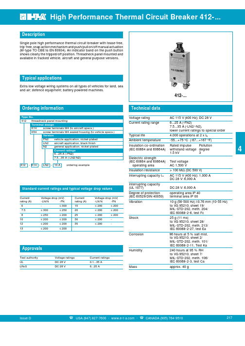
Description
Single pole high performance thermal circuit breaker with tease-free, trip-free, snap action mechanism and push/pull on/off manual actuation (M-type TO CBE to EN 60934). An indicator band on the push button shows clearly the tripped/off position. Threadneck panel mounted and available in tracked vehicle, aircraft and general purpose versions.
thickness 1.5 - 3 mm .059 - .118 in.
Internal connection diagram
line 1
2
Typical time/current characteristics
412-...-FN2 6...25 A
10000 1000 100
Trip time in seconds
25 g (11 ms) to VG 95210, sheet 28/ MIL-STD-202, meth. 213/ IEC 60068-2-27, test Ea
Approvals
Test authority UL
Voltage ratings DC 28 V
Current ratings 0.1...35 A
原装AMETEK阿美特克
AMETEK阿美特克咨..询1*37-99-4-528*06双环贸易为你提供阿美特克,点过的路过的千万不能错过了,相信我们会是你最终的选择。
阿美特克传感器板80485SE美国AMETEK阿美特克分析仪欢迎咨询详细内容AMETEK阿美特克发生器305010901SAMETEK氧化锆传感器71785SEAMETEK过滤器71849SEAMETEK镜头CH13-0007-tAMETEK电路板13-0307AMETEK铂电阻13-0236氧化锆锆管AMETEK71785SE阿美特克传感器板80485SEAMETEK比值分析仪测量池880324901AMETEK比值分析仪检测电路板880020901AMETEK阿美特克比值分析仪配件200880001AMETEK269323011AMETEK阿美特克温度控制器269323011AMETEK烟尘仪4200AMETEK阿美特克74422SEAMETEK射频导纳液位计UP010620B1AMETEK镉灯300-2070AMETEK 氧化锆头71063SE阿美特克传感器板80485SEAMETEK阿美特克过滤组件100-1848AMETEK阿美特克滤芯300-6217AMETEK 阿美特克氧化锆WDG1210/Insitu 72"AMETEK阿美特克露点仪3050AMETEK阿美特克气体分析仪Thermox-CMFA-P2000AMETEK阿美特克500124901AMETEK阿美特克硫磺比值仪光源电源880107902S阿美特克硫磺比值仪光源触发器880118901AMETEK阿美特克线性传感器P-10A-10KA238阿美特克传感器板80485SE阿美特克传感器板80485SEAMETEK阿美特克压力模块APM002CAMETEK阿美特克过滤器74422seAMETEK阿美特克储存箱880060901SAMETEK H2S分析仪H2S分析仪933-光源镉灯-300-2070H2S分析仪933-空心阴极铜线灯-300-8707AMETEK阿美特克马达119153-54阿美特克传感器板80485SE。
高功率密度交直流电源

高功率密度交直流电源
科电贸易高功率密度交直流电源的产品描述
AMETEK推出了California Instruments品牌Asterion系列程控交直流电源,将智能与灵活性能完美结合在一起,倾力打造处全新的交流电源解决方案。
该产品采用精密技术来实现高性能的程控交流和直流输出,产品外观时尚,将高功率密度整合到紧凑的机架中,并配备直观的触控屏幕界面,让您随意操控电源。
集中式的控制和无与伦比的模块化设计,使Asterion系列产品堪称是市场上适应性最强的平台。
其突破性的能力为高性价比、高精准度的电源设定了新的标准。
科电贸易高功率密度交直流电源的产品特点
●在1U/2U/4U/14U机箱上实现高功率密度,覆盖功率500VA–18kVA
●直观的触摸屏控制
●创新IX2™电流倍增技术
●多国语言显示的全球化操作界面
●自动并联技术,满足更高功率要求
●1U型号支持单相输出,2U/4U/14U型号单相三相输出可切换
●完整的航空电子测试套件(可选)
●1U/2U/4U型号均提供ATE版本
●标配LXI LAN,USB和RS232接口,选配GPIB接口
科电贸易高功率密度交直流电源的典型应用
●用于机载、电信及商用电子设备的轻型电源
●在所有三相上使用不同波形(甚至包含直流成分)来测试真实供电环境●频率和电压变化应用
●IEC标准电网扰动测试
●MIL-STD-704、DO-160、B787及ABD100机载标准测试
●AC-DC、DC-DC变换器及UPS供电测试
●ATE系统集成应用
型号列表。
键研科技 E3620A 和 E3630A 非可编程直流电源说明书

Keysight TechnologiesE3620A and E3630ANon-programmable DC Power Supplies Data SheetAffordable, Full-Featured Benchtop Power Supplies Provide Excellent Performance and FlexibilitySmooth turn-on and turn-off transitions keep power spikes out of your circuits.Auto-tracking permits equal or proportional voltage sharing, and allows control of output voltage from one master unit. The master and slave supplies have the same output polarity with respect to a common bus or ground. This operation is usefulwhere simultaneous turn-up, turn-down or proportional control of all power supplies is required.E3620A dual-output power supplyThe 50-watt E3620A dual-output power supply provides two 0 V to 25 Vdc outputs with the maximum current of 1 A to satisfy most bench requirements. The outputs are completely independent and isolated.E3630A triple-output power supply with auto-tracking featureThe 35-watt E3630A triple-output power supply provides three DC outputs: 0 to 6 V with a maximum current of 1 to 2.5 A and 0 to 20 V and 0 to %20 V with a maximum current of 0.5 A. An auto-tracking feature lets you use one voltage control to adjust the +20 V and %20 V outputs simultane-ously. The outputs track each other to within 1 percent, making it easy to adjust the power supply for circuits requiring balanced voltages.Multiple-outputnon-programmable modelsThe Keysight Technologies, Inc. E3620A and E3630A low-cost benchtop power supplies give you the performance of system power supplies at a decent price. Both supplies provide clean power with excellent regulation and a fast transient response.With multiple supplies in a compact unit, the E3620A and E3630A provide excellent performance while saving space on your bench. Both instruments feature a tight 0.01 percent line and load regulation and a low normal mode noise specification of less than 0.35 mV to ensure clean power for precision circuitry. With a common mode current specification of less than 1 μA, both multiple-output power supplies minimize the power line current injection.The E3620A and E3630A feature separate digital panel meters so you can monitor the voltage and current simultaneously. They also protect your DUT against overload and short-circuit damage.Reliable Power, Repeatable Results–Linear power supply –Dual or triple output–10-turn voltage and current control –Low noise and excellent regulationSpecificationsE3620A E3630AFeatures Isolated dual outputs, 10 turn pots CV, CL Tracking, CV, CL (± 20 V) CV, CF (+6 V) Number of outputs23Number of output ranges11DC output rating25 V, 1 A25 V, 1 A +6 V, 2.5 A +20 V, 0.5 A –20 V, 0.5 ALoad and line regulation< 0.01% + 2 mVRipple and Noise (20 Hz to 20 MHz)Normal mode voltage< 350 μVrms, < 1.5 mVppNormal mode current–Transient response time< 50 μsec following a change in output current from full load to half load for output to recover within: 15 mV Meter accuracy± 0.5% + 2 counts at 25 ºC ± 5 ºCOrdering informationE3620A Dual-output power supplyE3630A Triple-output power supplyStandard shipped accessories Product reference CD, power cordPower optionsOpt. 0E3 230 Vac ± 10%Opt. 0EM 115 Vac ± 10%Opt. 0E9 100 Vac ± 10%Rackmount kits*E3620ATo rackmount two instrumentsside-by-side–Lock-link Kit (P/N 5061-9694)–Flange Kit (P/N 5063-9212) or 34191A To rackmount one or two instruments in a sliding support shelf–Support Shelf (P/N 5063-9255)–Slide Kit (P/N 1494-0015) requiredfor support shelfFor a single instrument, also order filler panel (P/N 5002-3999)* Rackmounting with 1CM or lock-link/flange kit requires– Keysight or customer support rails– Keysight Support Rails-E3663AC.Supplemental CharacteristicsE3620A E3630AControl mode CV/CL CV/CL (± 20 V)CV/CF (+ 6 V)Common mode current< 1 μArmsMeter resolutionVoltage10 mV (0–20 V), 100 mV (> 20 V)10 mVCurrent 1 mA10 mATemperature coefficient per ºCVoltage< 0.02% + 1 mVCurrent–Output DriftVoltage Less than 0.1% + 5 mV total drift for 8 hours after initial warm-up of 30 minutesCurrent N/ATemperature range Derate output current 50% between 40 ºC to 55 ºCCooling Convection coolingIsolation± 240 VdcAC Input 100 Vac ± 10%, 47–63 Hz (opt. 0E9)115 Vac ± 10%, 47–63 Hz (std)230 Vac ± 10%, 47–63 Hz (0E3)Weight 5.0 kg (11.0 lbs) net, 6.25 kg (13.8 lbs) shipping 3.8 kg (8.4 lbs) net, 5.1 kg (11.3 lbs) shippingSize88.1 mm H x 212.3 mm W x 392.4 mm D3.5” H x 8.4” W x 15.4” D 88.1 mm H x 212.3 mm W x 318.4 mm D 3.5” H x 8.4” W x 12.5” DWarranty Three year for E3600 Series power suppliesThree months for standard shipped accessoriesProduct regulation Certified to CSA 22.2 No. 231; conforms to IEC 1010-1; carries CE mark; complies with CISPR-11,Group 1, Class A, KC South Korean EMC Mark, Canadian ICES/NMB-001, Australian C Tick MarkOther optionsOpt. 1CM or 34190A rackmount kit*(Only applicable for E3620A)Opt. UK6 Commercial calibrationcertificate with test result dataE3600A-100 Test lead kitManual setsPlease visit/find/manualsfor the latest revisions of manuals.This information is subject to change without notice.© Keysight Technologies, 2009 - 2018Published in USA, May 3, 20185968-9727ENmyKeysight/find/mykeysightA personalized view into the information most relevant to you. /find/emt_product_registrationRegister your products to get up-to-date product information and find warranty information.Keysight Services/find/serviceKeysight Services can help from acquisition to renewal across your instrument’s lifecycle. Our comprehensive service offerings—one-stop calibration, repair, asset management, technology refresh, consulting, training and more—helps you improve product qualityand lower costs.Keysight Assurance Plans/find/AssurancePlansUp to ten years of protection and no budgetary surprises to ensure your instruments are operating to specification, so you can rely on accurate measurements.Keysight Channel Partners/find/channelpartnersGet the best of both worlds: Keysight’s measurement expertise and product breadth, combined with channel partner convenience.Evolving Since 1939Our unique combination of hardware, software, services, and people can help you reach your next breakthrough. We are unlocking the future of technology.From Hewlett-Packard to Agilent to Keysight.For more information on KeysightTechnologies’ products, applications or services, please contact your local Keysight office. The complete list is available at:/find/contactus Americas Canada (877) 894 4414Brazil 55 11 3351 7010Mexico001 800 254 2440United States (800) 829 4444Asia Pacific Australia 1 800 629 485China800 810 0189Hong Kong 800 938 693India 1 800 11 2626Japan 0120 (421) 345Korea 080 769 0800Malaysia 1 800 888 848Singapore 180****8100Taiwan0800 047 866Other AP Countries (65) 6375 8100Europe & Middle East Austria 0800 001122Belgium 0800 58580Finland 0800 523252France 0805 980333Germany ***********Ireland 1800 832700Israel 1 809 343051Italy800 599100Luxembourg +32 800 58580Netherlands 0800 0233200Russia 8800 5009286Spain 800 000154Sweden 0200 882255Switzerland0800 805353Opt. 1 (DE)Opt. 2 (FR)Opt. 3 (IT)United Kingdom0800 0260637For other unlisted countries:/find/contactus(BP-9-7-17)/go/quality Keysight Technologies, Inc.DEKRA Certified ISO 9001:2015Quality Management System。
- 1、下载文档前请自行甄别文档内容的完整性,平台不提供额外的编辑、内容补充、找答案等附加服务。
- 2、"仅部分预览"的文档,不可在线预览部分如存在完整性等问题,可反馈申请退款(可完整预览的文档不适用该条件!)。
- 3、如文档侵犯您的权益,请联系客服反馈,我们会尽快为您处理(人工客服工作时间:9:00-18:30)。
评估计 算成本
讨论价 格策略
客户已经 有全面设 计
了解客 户的全 面设计
温度探头
PV 电池
温度控制器
利用温度控制器的温 度探头监测电池的温 度,当温度超过25度 温度控制器就通过模 拟信号接口给直流电 源发出指令,使电源 输出,开始供电,当 温度低于25度则发出 关闭直流电源输出的 命令,电源关闭。 尚德太阳能科技有限 公司已经从我公司购 买4套系统,运行正常
3.用户需要的软件(GUI-Graphic User Interface) 软件如何工作 软件的操作界面是什么样的 需要设置什么样的参数 输入输出都是什么样的 如何设置各种参数 如何保存各种参数 如何回读参数 生成报告需要显示哪些参数/波形/用户特殊要求
用户手册 GUI用户 操作界面
通过上图可以看到,用户需要8路独立的直流电源,给8组 PCB板供电(每个PCB板上有10个LED串联),来测试LED 的可靠性. 每个LED的需要的电流是在40mA-200mA可调节,每 个LED的工作电压是在2.4-3V之间。 需要多通道的电流,且每个通道之间不能相互干扰。 必须是独立的。 电流的误差允许在+/-3mA之间。不要超过这个规格。 必须每一个通道实现自动的5分钟开,然后5分钟关, 再自动开5分钟,然后关5分钟。。。。。。以此反复 至少连续运行2000小时。
模拟信号控制
直流电源 直流电压输出
用户需要的输入: 模拟(Analogue)控制 用户需要的输出: 直流电压输出(150V/300V) 用户需要的驱动程序:不需要 用户需要的操作界面: 在温度控制器发出关断指令 后直流电源相应的关断输出端,在输出过程中对电路 中的电流电压测量并回读
用户需要的输入: 模拟(Analogue)控制或者GPIB 用户需要的输出:每一路正确的电压电流输出和关断 用户需要的驱动程序:IVI/CVI 用户需要的操作软件:显示每一路的电流电压,工作 时间,输出关断状态,在电流异常情况下的报警
驱动程序
软件
测试报告 接口I/O源自销售销售销售
销售
销售 & Hunk
Aaron
Aaron
Aaron & Bruce
相关人 员
客户刚开 始概念设 计
没有前 景预算 太低 有大规 模需求 及推广 价值
直接推 销设备 现场了 解客户 的概念 设计 帮助客 户完成 全面的 设计
收到客 户需求
了解客 户用途
需要开发 系统
ATE自动测试系统基本知识
自动测试系统(ATE-Automatic Test Equipment) 通常是指在人工最少参与的情况下,按预先编制好 的测试程序,完成自动测试、分析处理、显示或输 出结果的系统。系统一旦正常工作,各种操作一般 都由系统自动完成。
1.用户需要的输出和输入I/O (Input/Output) 输入:模拟控制,数字控制 (RS232/GPIB/USB),LAN,LXI以太网 输出:测量何种参数 2.用户需要的驱动程序Driver CVI, IVI, IVCOM IVCOM这种驱动具有很强的通用性,虽然有可能降 低数据传输速度,但是能够在硬件更换的情况下不需 要改变软件,支持多种通用设备.
