E5C4-R20K中文资料
EOCR-3M420FM420使用说明书
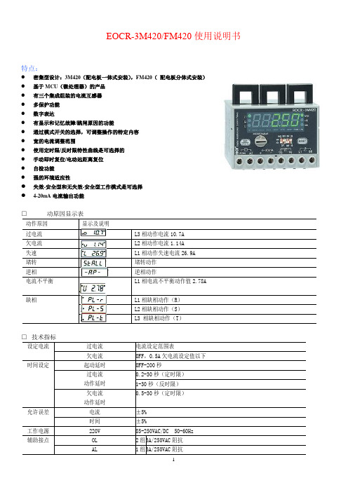
EOCR-3M420/FM420使用说明书特点:●密集型设计:3M420(配电板一体式安装),FM420(配电板分体式安装)●基于MCU(微处理器)的产品●有三个集成组装的电流互感器●多保护功能●数字表达●有显示和记忆故障/跳闸原因的功能●通过模式开关的选择,可调整操作的特定内容●宽的电流调整范围●使用定时限/反时限特性曲线是可选择的●手动即时复位/电动远距离复位●自检功能●强的环境适应性●失效-安全型和无失效-安全型工作模式是可选择●4-20mA电流输出功能□动原因显示表为使保护器能按要求起到保护作用,在其工作前应作必要的设置。
参照EOCR-3典型接线图完成接线。
根据实际情况将功能开关选择在合适的位置上(参照上述说明)。
接通工作电源,按下述方法设置参数。
□ 过电流值设置顺时针方向转动面板上的“MODE/Adjust ”钮至 位置。
这里0.5表示过电流值0.5A 。
若要改变此值,需按 “SET/store ”键,然后转动“MODE/Adjust ”钮,上述的值即可改变。
把这个值调整到电机铭牌上规定的额定值上(如无此值,推荐将此值放在电机实际运行电流的110-125%之间)。
再次按动“SET/store ”键,将该值存贮起来即可,若设置值超过10A 时,需将功能开关SW4 拨到60位置上,用前述方法调整到所需数值,如果超过60A ,则应根据需要配相应的外部互感器,并按第13条要求操作。
2.起动延时时间设置过电流值设置完成后,再将“MODE/Adjust ”钮顺时针方向转动,即可看到 显示。
dt 表示起动延时;10表示延时时间为10秒。
电机起动时其起动电流要达到电机额 定运转电流的5-7倍。
电机的起动电流在其转数没有达到额定 转数的80%之前并不减少;当达到额定转数的80%以后起动电 流急剧下降至额定电流值(过电流设定值)以下。
电流变化曲 线与过电流设定值交叉点的时间就是电机起动延时时间D-TIME (参见右图)。
CC4H-4S中文资料

Multiport Analog Modem CardBenefits• High-density , V .92 connections • V .34/33.6K Super G3 fax with Error Correction Mode • Supports leading remote access and fax software • Universal PCI and PCI ExpressThe MultiModem ® ISI server card is ideal for small- to mid-sized companies requiring analog dial-up remote access or a dedicated fax server solution. It provides up to eight built-in V .92/56K modems for cost-effective,high-density , server-based remote access. The MultiModem ISI server card also offers V .34/33.6K Super G3 fax and Error Correction Mode, that can reduce fax transmission time by more than half when compared to traditional fax modems.Features• Four or eight integrated V .92/56K modems• V .92/56K download speeds and 48K upload speeds when connecting with V .92 servers • Class 1.0 and Class 2.1 faxing at speeds to V .34/33.6K bps (Super G3)• Error Correction Mode (ECM) provides fast and reliable fax transmissions • V .44 compression improves data throughput rates • U.S. Caller ID reporting• Sustained data rates to 460.8K per port • Phone cables included• Compatible with Windows ® 2000/XP/2003/Vista/2008 (32-bit/64-bit) and Linux • Up to 4 cards per server• Remote configuration for centralized setup and mangement • 3.3V and 5V Universal PCI or PCI Express models • Compatible with PCI-X slot (Universal PCI models)• Flash memory for easy updates • T wo-year warrantyMultiModem ®ISIWorld Headquarters Tel: (763) 785-3500 (800) EMEA Headquarters Multi-Tech Systems (EMEA)United KingdomTel: +(44) 118-959 7774Multi-Tech Systems (EMEA) FranceTel: +(33) 1 49 19 22 06HighlightsCost-Effective & Scalable. The MultiModem ISI server card provides four or eight dial-up sessions using only one server slot. When demand exceeds one modem card, you can simply add up to three additional cards.V.92 Dial-out Connections. The MultiModem ISI server card supports V .92/56K dial-out and V .34/33.6K dial-inconnections. With V .92 dial-out, you can achieve an upload speed of 48K bps (30% increase over V .90 modems).Enhanced Fax Features. The MultiModem ISI server card supports V .34 fax and Error Correction Mode providingsignificant performance and reliability enhancements over previous fax standards. V .34 sends and receives faxes at speeds up to 33.6K, more than double the speed of the V .17/14.4K fax standard. Error Correction Mode adds reliablility while increasing performance of faxtransmissions. Together these enhancements increase the performance of the MultiModem ISI server card to levels previously only found in more expensive dedicated fax boards and machines.V.44 Compression. V .44 compression standard improves V .42bis data compression anywhere from 20 to 60%, up to as much as 200% for certain types of highly compressible data. This compression technique enables data throughput rates of higher than 300K bps.Simplify Remote Access. The fully-integrated MultiModem ISI server card is easy to set up and manage. You only have to connect the phone lines. There are no external modems and power cords to hassle with; plus it saves back office space since the modems are on the prehensive Service and Support. The Multi-Techcommitment to service means we provide a two-year product warranty and service that includes free telephone technical support, 24-hour web site and ftp support.Ordering InformationProductDescriptionRegion ISI5634UPCI/8 V .92, 8-Modem Card - Universal PCI Global ISI5634UPCI/4 V .92, 4-Modem Card - Universal PCI Global ISI9234PCIE/8 V .92, 8-Modem Card - PCI Express Global ISI9234PCIE/4V .92, 4-Modem Card - PCI ExpressGlobalSpecificationsModemData: V .92, V .90, enhanced V .34, V .32bis, V .22bis Error Correction: V .42, MNP Class 3 & 4Data Compression: V .44, V .42bis, MNP Class 5FaxStandards: V .34, V .17, V .29, V .27ter, V .21, T.30, T.30Annex A, T.30 Annex F , T.31, T.31 Annex B, T.32 Annex C, TR29.2 Class 2 RecommendationRates: 33.6K, 31.2K, 28.8K, 26.4K, 24K, 21.6K, 19.2K, 16.8K, 14.4K, 12K, 9600, 7200, 4800, 2400, 300 bps Error Correction: ECMCompression: MH (T.4), MR (T.4), & MMR (T.6)Conversion: Real time (on-the-fly) compression conversionCommands: Class 1, 2, 1.0, 2.0, 2.1Bus Type3.3V & 5V Universal PCI or PCI Express (x1)Operating System SupportWindows 2000/XP/2003/Vista/2008 (32-bit/64-bit) & LinuxCablingFan out cable with 1 or 2 RJ45 connectors & 4 or 8 RJ11 connectorsPhysical DescriptionUniversal PCI Models:13.87" L × 4.97" W; 8.7 oz (35.2 cm × 12.6 cm; 247 g)PCI Express Models:13.87" L × 4.97" W; 8.5 oz (35.2 cm × 12.6 cm; 241 g)Operating EnvironmentTemperature Range: +23° to +140° F (-5° to +60° C)ApprovalsCE MarkEMC: FCC Part 15 Class B, EN 55022, EN 55024Safety: UL/cUL 60950-1, EN 60950-1, AS/NZS 60950:2000, CCCTelecom: 47CFR Part 68, CS03, TBR21Other countries also includedCopyright © 2008 by Multi-Tech Systems, Inc. All rights reserved.6/08 86000323Made in Mounds View, MN, U.S.A.Features and specifications are subject to change without notice.Trademarks / Registered Trademarks: MultiModem, Multi-Tech, and theMulti-Tech logo: Multi-Tech Systems, Inc. / All other products and technologies are the trademarks or registered trademarks of their respective holders.。
小身材大内涵-Dell PowerEdge R420评测

小身材大内涵-Dell PowerEdge R420评测作者:暂无来源:《计算机世界》 2012年第32期■ 计算机世界评测实验室于泽自英特尔至强E5 系列处理器上市以来,各大厂商纷纷对各自的服务器产品线进行升级。
Dell 也不例外,相继推出了一系列新产品,也就是戴尔第十二代(12G)服务器。
相较上一代产品,12G 服务器在性能以及虚拟化的支持上有了很大的提升。
本次测试的是DellPowerEdgeR420( 以下简称R420),它是戴尔专为满足中小型企业一般需求或大型企业高IT 密度及性能需求而推出的一款产品。
设计篇外形方面,R420 采用1U 高度设计,而且在前后面板空间利用上几乎做到极致。
前面板除了8 个2.5英寸硬盘插槽外,还配有光驱以及电源按钮、NMI 按钮,系统识别按钮,LCD 面板及VGA、USB 等多种接口。
背面板同样紧凑、合理,不仅有PCIe 扩展插槽,串行接口、VGA 接口、USB 接口、网络接口等常见的配置,还配有vFlash 卡插槽,这在以往的服务器配置中可不常见。
R420 的内部布局同样错落有致,虽然是1U 服务器,但其最多可配备两颗至强E5-2400 系列处理器,最多可拥有16 个物理核心;搭配12 个DIMM 插槽,最多可达到192GB 的内存容量,对于当下大热的虚拟化环境,可以有不错的支持;另外,R420 最多可搭载8 个2.5 英寸热插拔SAS、SATA 或SSD 驱动器或4 个3.5 英寸热插拔硬盘,最大存储容量可达到12TB。
当然,如此多的部件散热问题不容小觑,这方面R420 搭载6 个小型风扇,以保证整台机器的散热。
在实际测试中,R420 交出了满意的答卷,整个测试过程中并没有出现过热的情况。
另外值得一提的是,R420 所配备的iDRAC 7 卡,通过与服务器主板上的管理芯片BMC 进行通信,监控、管理服务器的硬件状态信息。
由于它直接嵌入主板内,所以与服务器上的OS无关,对于管理员而言是个不错的工具。
UPC4574G2-E1中文资料
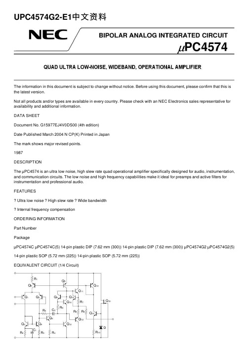
UPC4574G2-E1中⽂资料The information in this document is subject to change without notice. Before using this document, please confirm that this is the latest version.Not all products and/or types are available in every country. Please check with an NEC Electronics sales representative for availability and additional information.DATA SHEETDocument No. G15977EJ4V0DS00 (4th edition)Date Published March 2004 N CP(K) Printed in JapanThe mark shows major revised points.1987DESCRIPTIONThe µPC4574 is an ultra low noise, high slew rate quad operational amplifier specifically designed for audio, instrumentation, and communication circuits. The low noise and high frequency capabilities make it ideal for preamps and active filters for instrumentation and professional audio.FEATURESUltra low noise High slew rate Wide bandwidthInternal frequency compensationORDERING INFORMATIONPart NumberPackageµPC4574C µPC4574C(5) 14-pin plastic DIP (7.62 mm (300)) 14-pin plastic DIP (7.62 mm (300)) µPC4574G2 µPC4574G2(5) 14-pin plastic SOP (5.72 mm (225)) 14-pin plastic SOP (5.72 mm (225))EQUIVALENT CIRCUIT (1/4 Circuit)I I I NVVPIN CONFIGURATION (Top View)OUT 4I I4I N4V ?I N3I I3OUT 3OUT 1I I1I N1V +I N2I I2OUT 2PC4574C, 4574C(5), 4574G2, 4574G2(5)µData Sheet G15977EJ4V0DS2ABSOLUTE MAXIMUM RATINGS (T A = 25°C)Parameter SymbolRatings Unit Voltage between V +and V ? Note1V +V0.3 to +36VDifferential Input Voltage V ID ±30 V Input VoltageNote2V IV ??0.3 to V ++0.3 V Output VoltageNote3V OV ??0.3 to V + +0.3VC Package Note4570 mW Power Dissipation G2 PackageNote5P T 550 mW Output Short Circuit DurationNote610 sec Operating Ambient Temperature T A ?20 to +80 °C Storage TemperatureT stg55 to +125°CNotes 1. Reverse connection of supply voltage can cause destruction.2. The input voltage should be allowed to input without damage or destruction. Even during the transition periodof supply voltage, power on/off etc., this specification should be kept. The normal operation will establish when the both inputs are within the Common Mode Input Voltage Range of electrical characteristics.3. This specification is the voltage which should be allowed to supply to the output terminal from externalwithout damage or destructive. Even during the transition period of supply voltage, power on/off etc., this specification should be kept. The output voltage of normal operation will be the Output Voltage Swing of electrical characteristics.4. Thermal derating factor is –7.6 mW/°C when ambient temperature is higher than 50°C.5. Thermal derating factor is –5.5 mW/°C when ambient temperature is higher than 25°C.6. Pay careful attention to the total power dissipation not to exceed the absolute maximum ratings, Note 4 andNote 5.RECOMMENDED OPERATING CONDITIONSParameter Symbol MIN. TYP. MAX. UnitSupply Voltage V ± ±4 ±16 V Output Current I O±10 mASource Resistance R S 50k ?Capacitive Load (A V = +1)C L 100 pFµPC4574C, µPC4574G2±Notes 7. Input bias currents flow out from IC. Because each currents are base current of PNP-transistor on input stage.8.This current flows irrespective of the existence of use.Data Sheet G15977EJ4V0DS 3µPC4574C(5), µPC4574G2(5)±Notes 7. Input bias currents flow out from IC. Because each currents are base current of PNP-transistor on input stage.8.This current flows irrespective of the existence of use.4Data Sheet G15977EJ4V0DSMEASUREMENT CIRCUITFig.1 Total Harmonic Distortion Measurement CircuitnFig.3 Flat Noise Measurement Circuit (FLAT+JIS A)V O = 40 dB x V n100 V n =V O40 dBData Sheet G15977EJ4V0DS 5Data Sheet G15977EJ4V0DS6TYPICAL PERFORMANCE CHARACTERISTICS (T A = 25°C, TYP.) T A - Operating Ambient Temperature - ?CPOWER DISSIPATIONP T - T o t a l P o w e r D i s s i p a t i o n - m W800600400200020*********20406080100120110010 k 1 M 1 k 10100 k 10 Mf - Frequency - HzOPEN LOOP FREQUENCY RESPONSEA V - O p e n L o o p V o l t a g e G a i n - d BV ± = ±15 V202040608021.510.50?0.5?1?1.5?2T A - Operating Ambient Temperature - ?CINPUT OFFSET VOLTAGEV I O - I n p u t O f f s e t V o l t a g e - m V= ±15 VV ±each 5 samples data806040200?20550530510490470450T A - Operating Ambient Temperature - ?CINPUT BIAS CURRENTI B - I n p u t B i a s C u r r e n t - n A= ±15 VV ±f - Frequency - HzLARGE SIGNAL FREQUENCY RESPONSE V o m - O u t p u t V o l t a g e S w i n g - V p -p 01020301001 k 10 k 100 k 1 M 10 MV = ±15 V±R L = 10 k ?I O - Output Current - mAOUTPUT CURRENT LIMITV O - O u t p u t V o l t a g e - V±±5±10±15T A - Operating Ambient Temperature - ?CSUPPLY CURRENTI C C - S u p p l y C u r r e n t - m A12963204020060800V = ±15 V±SUPPLY CURRENTI C C - S u p p l y C u r r e n t - m A12963±10±20V - Supply Voltage - V±Data Sheet G15977EJ4V0DS7COMMON MODE INPUT VOLTAGE RANGE V I C M - C o m m o n M o d e I n p u t V o l t a g e R a n g e - V 20100±10±20V - Supply Voltage - V±VOLTAGE FOLLOWER PULSE RESPONSE V O - O u t p u t V o l t a g e - V10551002468t - Time - sµV = ±15 V ±A V = 1R L = 2 k ?INPUT NOISE VOLTAGE (FLAT + JIS A)V n - I n p u t N o i s e V o l t a g e - V r .m .s .1001010.1101001 k10 k100 kR S - Source Resistance - ?V = ±15 V±µf - Frequency - HzINPUT EQUIVALENT NOISE VOLTAGE DENSITY e n - I n p u t E q u i v a l e n t N o i s e V o l t a g e D e n s i t y - n V / H z20468100 1 k10 k 100 k10±R S = 100 VTOTAL HARMONIC DISTORTIONT H D - T o t a l H a r m o n i c D i s t o r t i o n - %10.0010.010.10.000110100 1 k10 k 100 kf - Frequency - HzV = ±15 V ±V O = 3 V r.m.s.A V = 1R L = 2 k ?Data Sheet G15977EJ4V0DS8PACKAGE DRAWINGS (Unit: mm)14-PIN PLASTIC DIP (7.62 mm (300))ITEM MILLIMETERS A 19.22±0.22.14 MAX.F I J D 1.32±0.12G 3.6±0.3C B 2.54 (T.P.)0.50±0.10R 0~15°H 0.51 MIN.K 7.62 (T.P.)L 6.4±0.23.554.3±0.2N 0.25NOTES1. Each lead centerline is located within 0.25 mm ofits true position (T.P.) at maximum material condition.2. ltem "K" to center of leads when formed parallel.P14C-100-300B1-3M 0.25+0.10?0.05Data Sheet G15977EJ4V0DS9ITEM B C I 14-PIN PLASTIC SOP (5.72 mm (225))D E G H J PMILLIMETERS 1.27 (T.P.)1.42 MAX.A 10.2±0.264.4±0.10.1±0.10.426.5±0.21.49+0.08?0.071.1±0.163°+7°?3°NOTEEach lead centerline is located within 0.1 mm ofits true position (T.P.) at maximum material condition.F 1.59+0.21?0.2K L M N 0.6±0.20.170.10.10+0.08?0.07S14GM-50-225B, C-6RECOMMENDED SOLDERING CONDITIONSThe µPC4574 should be soldered and mounted under the following recommended conditions.For soldering methods and conditions other than those recommended below, contact an NEC Electronics sales representative.For technical information, see the following website.Semiconductor Device Mount Manual (/doc/015a7dda76a20029bd642de6.html/pkg/en/mount/index.html)Type of Surface Mount DeviceµPC4574G2, 4574G2(5): 14-pin plastic SOP (5.72 mm (225))Process ConditionsSymbol Infrared Ray Reflow Peak temperature: 230°C or below (Package surface temperature),Reflow time: 30 seconds or less (at 210°C or higher),Maximum number of reflow processes: 1 time.IR30-00-1Vapor Phase Soldering Peak temperature: 215°C or below (Package surface temperature),Reflow time: 40 seconds or less (at 200°C or higher),Maximum number of reflow processes: 1 time.VP15-00-1Wave Soldering Solder temperature: 260°C or below, Flow time: 10 seconds or less,Maximum number of flow processes: 1 time,Pre-heating temperature: 120°C or below (Package surface temperature).WS60-00-1Partial Heating Method Pin temperature: 300°C or below,Heat time: 3 seconds or less (Per each side of the device).–Caution Apply only one kind of soldering condition to a device, except for "partial heating method", or thedevice will be damaged by heat stress.Type of Through-hole DeviceµPC4574C, 4574C(5): 14-pin plastic DIP (7.62 mm (300))Process ConditionsWave Soldering (only to leads) Solder temperature: 260°C or below, Flow time: 10 seconds or less.Partial Heating Method Pin temperature: 300°C or below,Heat time: 3 seconds or less (per each lead).Caution For through-hole device, the wave soldering process must be applied only to leads, and make sure that the package body does not get jet soldered.Data Sheet G15977EJ4V0DS10The information in this document is current as of March, 2004. The information is subject to change without notice. For actual design-in, refer to the latest publications of NEC Electronics data sheets or data books, etc., for the most up-to-date specifications of N EC Electronics products. N ot all products and/or types are available in every country. Please check with an N EC Electronics sales representative for availability and additional information.No part of this document may be copied or reproduced in any form or by any means without the prior written consent of NEC Electronics. NEC Electronics assumes no responsibility for any errors that may appear in this document.NEC Electronics does not assume any liability for infringement of patents, copyrights or other intellectual property rights of third parties by or arising from the use of NEC Electronics products listed in this document or any other liability arising from the use of such products. No license, express, implied or otherwise, is granted under any patents, copyrights or other intellectual property rights of NEC Electronics or others.Descriptions of circuits, software and other related information in this document are provided for illustrative purposes in semiconductor product operation and application examples. The incorporation of these circuits, software and information in the design of a customer's equipment shall be done under the full responsibility of the customer. NEC Electronics assumes no responsibility for any losses incurred by customers or third parties arising from the use of these circuits, software and information.While NEC Electronics endeavors to enhance the quality, reliability and safety of NEC Electronics products, customers agree and acknowledge that the possibility of defects thereof cannot be eliminated entirely. To minimize risks of damage to property or injury (including death) to persons arising from defects in NEC Electronics products, customers must incorporate sufficient safety measures in their design, such as redundancy, fire-containment and anti-failure features.NEC Electronics products are classified into the following three quality grades: "Standard", "Special" and "Specific".The "Specific" quality grade applies only to NEC Electronics products developed based on a customer-designated "quality assurance program" for a specific application. The recommended applications of an NEC Electronics product depend on its quality grade, as indicated below. Customers must check the quality grade of each NEC Electronics product before using it in a particular application."Standard":Computers, office equipment, communications equipment, test and measurement equipment, audioand visual equipment, home electronic appliances, machine tools, personal electronic equipment and industrial robots. "Special":Transportation equipment (automobiles, trains, ships, etc.), traffic control systems, anti-disastersystems, anti-crime systems, safety equipment and medical equipment (not specifically designed for life support). "Specific":Aircraft, aerospace equipment, submersible repeaters, nuclear reactor control systems, lifesupport systems and medical equipment for life support, etc.The quality grade of NEC Electronics products is "Standard" unless otherwise expressly specified in NEC Electronics data sheets or data books, etc. If customers wish to use NEC Electronics products in applications not intended by NEC Electronics, they must contact an NEC Electronics sales representative in advance to determine NEC Electronics' willingness to support a given application.(Note)(1)"NEC Electronics" as used in this statement means NEC Electronics Corporation and also includes itsmajority-owned subsidiaries.(2)"NEC Electronics products" means any product developed or manufactured by or for NEC Electronics (asdefined above).M8E 02. 11-1。
R4000,高压二极管中文资料
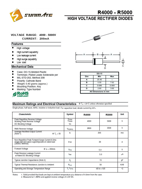
HIGH VOLTAGE RECTIFIER DIODES
VOLTAGE RANGE: 4000 - 5000V CURRENT: 200m A
Features
! ! ! ! !
High voltage High current capability Low leakage current High surge capability Low cost
1
AMBIENT TEMPERATURE, (
10 100 NUMBER OF CYCLES AT 60Hz
INSTANTANEOUS REVERSE CURRENT, (uA)
FIG. 3 - TYPICAL REVERSE CHARACTERISTICS
10 6 4 2 1.0 .6 .4 .2 .1 .06 .04 .02 .01
IFSM
30
A
VFM IRM Cj RqJA Tj, TSTG
5.0 5.0 15 50 -65 to +125
V mA pF K/W °C
Notes:
1. Valid provided that leads are kept at ambient temperature at a distance of 9.5mm from the case. 2. Measured at 1.0MHz and applied reverse voltage of 4.0V DC.
Symbol VRRM VRWM VR VR(RMS) IO
R4000
4000
R5000
5000
Unit
V
2800 200
3500
V mA
测速雷达主要设备功能及技术参数

测速雷达主要设备功能及技术参数测速雷达型号:KTR-C3(品牌:KITOZER/开拓者)采用高速DSP信号处理芯片、0.1秒快速捕捉。
1)设计小巧轻便、制作精良。
2)纯铸铁结构,坚固耐用。
3)232串口输出。
4)精确度高,捕捉目标速度快。
5)动态时具有同向功能。
6)静态时可分别检测来车、去车。
7)静态测速范围:0~322 KPH。
8)移动测速范围:19~322KPH。
9)环境要求:温度:-30度 ~ +70度;湿度:0 % ~ 90% 。
10)Ka波段窄波雷达,微波频率:34.7GHz(Ka-band),可有效规避探测狗检测。
11)发射角:±4度。
12)规格:重:0.52kg、直径:6.7cm、长:11.8cm。
13)精确度:+/-1KPH。
高清摄像机(品牌:KITOZER/开拓者)高清摄像机功能:CCD成像,200万象素,主要端口有:闪光灯同步口,通过同步线与闪光灯连接;拍照触发口,当收到外部脉冲触发信号时,高清摄像机会抓取一张图片,脉冲信号由独立的拍照触发器发出;网口(100M),与控制主机连接,接收参数配置,上传图片,也可接收带由协议内容的抓拍命令。
产品详细参数表百万像素变焦镜头日本精工本次中煤平朔公司系统百万像素变焦镜头选型为日本精工SE5018MP产品,AVENIR ETOKU(日本精工)十几年来始终专心于监控镜头的市场发展,成为中国安防监控领域用得最多的专业镜头。
本次系统高清摄像机选型为广州莱安智能化系统开发有限公司出品的KTR200A型高清摄像机。
KTR200A是集成一体的高速彩色/单色智能工业相机,采用总像素200万像素的CCD图像传感器,具有处理速度快、分辨率高、图像质量好等特点。
广泛应用于智能交通、电子警察、卡口、高速公路、停车厂等领域的检测和识别。
百万像素网络拍照摄像一体机,将高清图像抓拍、标清视频摄像完美结合,超高清晰度,分辨率达130万~500万像素,专业用于如平安城市建设、机场、银行、道路卡口监控及牌照识别等安全防范领域,能够为客户提供专业的可定制产品及服务,支持后续增值开发。
常用三极管参数大全

玉林万顺达电脑芯片级维修资料 2010-07-20整理玉林万顺达电脑芯片级维修资料 2010-07-20整理玉林万顺达电脑芯片级维修资料 2010-07-20整理玉林万顺达电脑芯片级维修资料 2010-07-20整理玉林万顺达电脑芯片级维修资料 2010-07-20整理玉林万顺达电脑芯片级维修资料 2010-07-20整理玉林万顺达电脑芯片级维修资料 2010-07-20整理玉林万顺达电脑芯片级维修资料 2010-07-20整理玉林万顺达电脑芯片级维修资料 2010-07-20整理玉林万顺达电脑芯片级维修资料 2010-07-20整理玉林万顺达电脑芯片级维修资料 2010-07-20整理玉林万顺达电脑芯片级维修资料 2010-07-20整理玉林万顺达电脑芯片级维修资料 2010-07-20整理玉林万顺达电脑芯片级维修资料 2010-07-20整理玉林万顺达电脑芯片级维修资料 2010-07-20整理玉林万顺达电脑芯片级维修资料 2010-07-20整理玉林万顺达电脑芯片级维修资料 2010-07-20整理玉林万顺达电脑芯片级维修资料 2010-07-20整理玉林万顺达电脑芯片级维修资料 2010-07-20整理玉林万顺达电脑芯片级维修资料 2010-07-20整理玉林万顺达电脑芯片级维修资料 2010-07-20整理玉林万顺达电脑芯片级维修资料 2010-07-20整理玉林万顺达电脑芯片级维修资料 2010-07-20整理玉林万顺达电脑芯片级维修资料 2010-07-20整理玉林万顺达电脑芯片级维修资料 2010-07-20整理玉林万顺达电脑芯片级维修资料 2010-07-20整理玉林万顺达电脑芯片级维修资料 2010-07-20整理玉林万顺达电脑芯片级维修资料 2010-07-20整理玉林万顺达电脑芯片级维修资料 2010-07-20整理玉林万顺达电脑芯片级维修资料 2010-07-20整理。
2N5484中文资料

**L2 **L3
6 turns, (approx. — depends upon circuit layout) AWG #24 enameled copper wire, close wound on 7/32″ ceramic coil form. Tuning provided by an aluminum slug. 1 turn, AWG #16 enameled copper wire, 3/8″ I.D. (AIR CORE). 1/2 turn, AWG #16 enameled copper wire, 1/4″ I.D. (AIR CORE).
POWER GAIN
24 f = 100 MHz
20 PG , POWER GAIN (dB)
16
12
400 MHz Tchannel = 25°C VDS = 15 Vdc VGS = 0 V 0 2.0 4.0 6.0 8.0 10 ID, DRAIN CURRENT (mA) 12 14
8.0 4.0
Figure 2. 100 MHz and 400 MHz Neutralized Test Circuit
NOISE FIGURE
(Tchannel = 25°C)
10 ID = 5.0 mA 8.0 NF, NOISE FIGURE (dB) NF, NOISE FIGURE (dB) 5.5 6.5 VDS = 15 V VGS = 0 V
1 2 3
CASE 29–04, STYLE 5 TO–92 (TO–226AA)
ELECTRICAL CHARACTERISTICS (TA = 25°C unless otherwise noted)
protel_dxp_2004常用元器件中英文对照及基本封装

protel dxp 2004 元件库中的常用元件初学protel DXP 碰到最多的问题就是:不知道元件放在哪个库中。
这里我收集了DXP2004常用元件库下常见的元件。
使用时,只需在libary中选择相应的元件库后,输入英文的前几个字母就可看到相应的元件了。
通过添加通配符*,可以扩大选择范围。
下面这些库元件都是DXP 2004自带的不用下载。
########### DXP2004下Miscellaneous Devices.Intlib元件库中常用元件有:电阻系列(res*)排组(res pack*)电感(inductor*)电容(cap*,capacitor*)二极管系列(diode*,d*)三极管系列(npn*,pnp*,mos*,MOSFET*,MESFET*,jfet*,IGBT*)运算放大器系列(op*)继电器(relay*)8位数码显示管(dpy*)电桥(bri*bridge)光电耦合器( opto* ,optoisolator )光电二极管、三极管(photo*)模数转换、数模转换器(adc-8,dac-8)晶振(xtal)电源(battery)喇叭(speaker)麦克风(mic*)小灯泡(lamp*)响铃(bell)天线(antenna)保险丝(fuse*)开关系列(sw*)跳线(jumper*)变压器系列(trans*)(tube*)(scr)(neon)(buzzer)(coax)晶振(crystal oscillator)的元件库名称是Miscellaneous Devices.Intlib, 在search栏中输入*soc 即可。
########### DXP2004下Miscellaneous connectors.Intlib元件库中常用元件有:(con*,connector*)(header*)(MHDR*)定时器NE555P 在库TI analog timer circit.Intlib中电阻AXIAL无极性电容RAD电解电容RB-电位器VR二极管DIODE三极管TO电源稳压块78和79系列TO-126H和TO-126V场效应管和三极管一样整流桥D-44 D-37 D-46单排多针插座CON SIP双列直插元件DIP晶振XTAL1电阻:RES1,RES2,RES3,RES4;封装属性为axial系列无极性电容:cap;封装属性为RAD-0.1到rad-0.4电解电容:electroi;封装属性为rb.2/.4到rb.5/1.0电位器:pot1,pot2;封装属性为vr-1到vr-5二极管:封装属性为diode-0.4(小功率)diode-0.7(大功率)三极管:常见的封装属性为to-18(普通三极管)to-22(大功率三极管)to-3(大功率达林顿管)电源稳压块有78和79系列;78系列如7805,7812,7820等79系列有7905,7912,7920等常见的封装属性有to126h和to126v整流桥:BRIDGE1,BRIDGE2: 封装属性为D系列(D-44,D-37,D-46)电阻: AXIAL0.3-AXIAL0.7 其中0.4-0.7指电阻的长度,一般用AXIAL0.4 瓷片电容:RAD0.1-RAD0.3. 其中0.1-0.3指电容大小,一般用RAD0.1电解电容:RB.1/.2-RB.4/.8 其中.1/.2-.4/.8指电容大小.一般<100uF用RB.1/.2,100uF-470uF用RB.2/.4,>470uF用RB.3/.6二极管: DIODE0.4-DIODE0.7 其中0.4-0.7指二极管长短,一般用DIODE0.4 发光二极管:RB.1/.2集成块: DIP8-DIP40, 其中8-40指有多少脚,8脚的就是DIP8贴片电阻0603表示的是封装尺寸与具体阻值没有关系但封装尺寸与功率有关通常来说0201 1/20W0402 1/16W0603 1/10W0805 1/8W1206 1/4W电容电阻外形尺寸与封装的对应关系是:0402=1.0x0.50603=1.6x0.80805=2.0x1.21206=3.2x1.61210=3.2x2.51812=4.5x3.22225=5.6x6.5关于零件封装我们在前面说过,除了DEVICE.LIB库中的元件外,其它库的元件都已经有了固定的元件封装,这是因为这个库中的元件都有多种形式:以晶体管为例说明一下:晶体管是我们常用的的元件之一,在DEVICE.LIB库中,简简单单的只有NPN与PNP之分,但实际上,如果它是NPN的2N3055那它有可能是铁壳子的TO—3,如果它是NPN 的2N3054,则有可能是铁壳的TO-66或TO-5,而学用的CS9013,有TO-92A,TO-92B,还有TO-5,TO-46,TO-52等等,千变万化.还有一个就是电阻,在DEVICE库中,它也是简单地把它们称为RES1和RES2,不管它是100Ω还是470KΩ都一样,对电路板而言,它与欧姆数根本不相关,完全是按该电阻的功率数来决定的我们选用的1/4W和甚至1/2W的电阻,都可以用AXIAL0.3元件封装,而功率数大一点的话,可用AXIAL0.4,AXIAL0.5等等.现将常用的元件封装整理如下:电阻类及无极性双端元件AXIAL0.3-AXIAL1.0无极性电容RAD0.1-RAD0.4有极性电容RB.2/.4-RB.5/1.0二极管DIODE0.4及DIODE0.7石英晶体振荡器XTAL1晶体管、FET、UJT TO-xxx(TO-3,TO-5)可变电阻(POT1、POT2) VR1-VR5当然,我们也可以打开C:\Client98\PCB98\library\advpcb.lib库来查找所用零件的对应封装.这些常用的元件封装,大家最好能把它背下来,这些元件封装,大家可以把它拆分成两部分来记如电阻AXIAL0.3可拆成AXIAL和0.3,AXIAL翻译成中文就是轴状的,0.3则是该电阻在印刷电路板上的焊盘间的距离也就是300mil(因为在电机领域里,是以英制单位为主的.同样的,对于无极性的电容,RAD0.1-RAD0.4也是一样;对有极性的电容如电解电容,其封装为RB.2/.4,RB.3/.6等,其中“.2”为焊盘间距,“.4”为电容圆筒的外径.对于晶体管,那就直接看它的外形及功率,大功率的晶体管,就用TO—3,中功率的晶体管,如果是扁平的,就用TO-220,如果是金属壳的,就用TO-66,小功率的晶体管,就用TO-5,TO-46,TO-92A等都可以,反正它的管脚也长,弯一下也可以.对于常用的集成IC电路,有DIPxx,就是双列直插的元件封装,DIP8就是双排,每排有4个引脚,两排间距离是300mil,焊盘间的距离是100mil.SIPxx就是单排的封装.等等.值得我们注意的是晶体管与可变电阻,它们的包装才是最令人头痛的,同样的包装,其管脚可不一定一样.例如,对于TO-92B之类的包装,通常是1脚为E(发射极),而2脚有可能是B极(基极),也可能是C(集电极);同样的,3脚有可能是C,也有可能是B,具体是那个,只有拿到了元件才能确定.因此,电路软件不敢硬性定义焊盘名称(管脚名称),同样的,场效应管,MOS管也可以用跟晶体管一样的封装,它可以通用于三个引脚的元件.Q1-B,在PCB里,加载这种网络表的时候,就会找不到节点(对不上).在可变电阻上也同样会出现类似的问题;在原理图中,可变电阻的管脚分别为1、W、及2,所产生的网络表,就是1、2和W,在PCB电路板中,焊盘就是1,2,3.当电路中有这两种元件时,就要修改PCB与SCH之间的差异最快的方法是在产生网络表后,直接在网络表中,将晶体管管脚改为1,2,3;将可变电阻的改成与电路板元件外形一样的1,2,3即可.protel99se常用元件封装电阻:RES1,RES2,RES3,RES4;封装属性为axial系列无极性电容:cap;封装属性为RAD-0.1到rad-0.4电解电容:electroi;封装属性为rb.2/.4到rb.5/1.0电位器:pot1,pot2;封装属性为vr-1到vr-5二极管:封装属性为diode-0.4(小功率)diode-0.7(大功率)三极管:常见的封装属性为to-18(普通三极管)to-22(大功率三极管)to-3(大功率达林顿管)电源稳压块有78和79系列;78系列如7805,7812,7820等79系列有7905,7912,7920等常见的封装属性有to126h和to126v整流桥:BRIDGE1,BRIDGE2: 封装属性为D系列(D-44,D-37,D-46)电阻:AXIAL0.3-AXIAL0.7其中0.4-0.7指电阻的长度,一般用AXIAL0.4 瓷片电容:RAD0.1-RAD0.3。
CD4094中文资料
*4094 与74ls164 的编程使用区别,仅仅在于多了一个1脚锁存端口。
当1脚为高电平时,其使用方法与164一模一样。
各位老师可以在以前164驱动的程序里,直接将加入将1脚置为高电平即可。
**另外,当1脚为低电平时,其输出引脚被锁定,Q引脚输出数据不会变化。
**但当锁存(1脚为低电平时),你跟4094通讯,可以使其内部数据改变,改变后,将1脚置为高电平,其Q输出引脚会被立即更新。
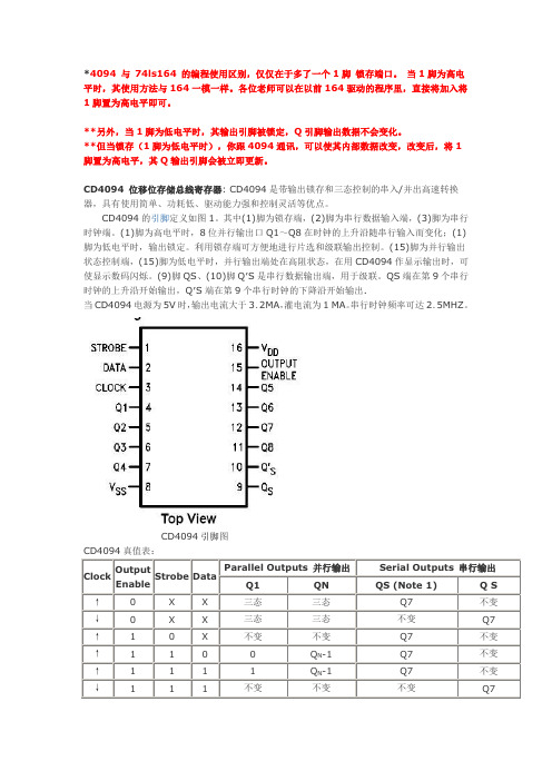
CD4094 位移位存储总线寄存器: CD4094是带输出锁存和三态控制的串入/并出高速转换器,具有使用简单、功耗低、驱动能力强和控制灵活等优点。
CD4094的引脚定义如图1。
其中(1)脚为锁存端,(2)脚为串行数据输入端,(3)脚为串行时钟端。
(1)脚为高电平时,8位并行输出口Q1~Q8在时钟的上升沿随串行输入而变化;(1)脚为低电平时,输出锁定。
利用锁存端可方便地进行片选和级联输出控制。
(15)脚为并行输出状态控制端,(15)脚为低电平时,并行输出端处在高阻状态,在用CD4094作显示输出时,可使显示数码闪烁。
(9)脚QS、(10)脚Q′S是串行数据输出端,用于级联。
QS端在第9个串行时钟的上升沿开始输出,Q′S端在第9个串行时钟的下降沿开始输出.当CD4094电源为5V时,输出电流大于3.2MA,灌电流为1 MA。
串行时钟频率可达2.5MHZ。
CD4094引脚图CD4094真值表:Clock OutputEnableStrobe DataParallel Outputs 并行输出Serial Outputs 串行输出Q1 QN QS (Note 1) Q S↑0 X X 三态三态Q7 不变↓0 X X 三态三态不变Q7 ↑ 1 0 X 不变不变Q7 不变↑ 1 1 0 0 Q N-1 Q7 不变↑ 1 1 1 1 Q N-1 Q7 不变↓ 1 1 1 不变不变不变Q7CD4094内部电路方框图Absolute Maximum Ratings 绝对最大额定值:Supply Voltage电源电压(VDD) -0.5 to +18 VDCInput Voltage输入电压(VIN) 838电子-0.5 to VDD +0.5 VDCStorage Temperature Range储存温度范围(TS) -65℃to +150℃Power Dissipation功耗(PD)Dual-In-Line 普通双列封装新艺图库700 mWSmall Outline 小外形封装500 mWLead Temperature 焊接温度(TL)Soldering, 10 seconds)(焊接10秒)260℃Recommended Operating Conditions 建议操作条件:DC Supply Voltage 直流供电电压(VDD) +3.0 to +15 VDC Input Voltage输入电压(VIN) 838电子0 to VDD VDC Operating Temperature Range工作温度范围(TA) -40℃to +85℃DC Electrical Characteristics 直流电气特性:Symbol 符号Parameter参数Conditions 条件-40°C +25°C +85°C Units单位最小最大最小典型最大最小最大IDD QuiescentDeviceCurrent静态电流VDD = 5.0V 20 20 150μA VDD = 10V 40 40 300VDD = 15V 80 80 600VOL LOW LevelOutputVDD=5.0V|IO|≤1.μA0.05 0 0.05 0.05V VDD=10V 0.05 0 0.05 0.05Voltage 输出低电平电压VDD=15V0.050.050.05VOHHIGH Level OutputVoltage 输出高电平电压VDD=5.0V|IO|≤1μA 4.954.955.0 4.95 VVDD=10V 9.959.95 10.0 9.95VDD=15V14.9514.95 15.014.95VILLOW Level InputVoltage 输入低电平电压VDD = 5.0V, VO =0.5V or 4.5V 1.5 1.5 1.5 V VDD = 10V, VO =1.0V or 9.0V3.0 3.0 3.0 VDD = 15V, VO = 1.5V or 13.5V 838电子4.04.0 4.0VIHHIGH Level InputVoltage 输入高电平电压VDD = 5.0V, VO = 0.5V or 4.5V 3.5 3.5 3.5 VVDD = 10V, VO = 1.0V or 9.0V7.0 7.07.0 VDD = 15V, VO = 1.5V or 13.5V11.011.011.0 IOLLOW Level OutputCurrent 输出低电平电流 (Note 4)VDD=5.0V,VO=0.4V 0.52 0.44 0.88 0.36 mAVDD=10V,VO=0.5V 1.31.12.25 0.9VDD=15V,VO=1.5V 3.6 3.08.82.4 IOHHIGH Level OutputCurrent 输出高电平电流 (Note 4)VDD=5.0V,VO =4.6V -0.52 -0.44 0.88 -0.36 mAVDD =10V,VO= 9.5V -1.3-1.1 2.25-0.9VDD=15V,VO =13.5V -3.6 -3.0 8.8-2.4IINInputCurrent 输入电流 VDD =15V,VIN =0V -0.3 -0.3 -1.0 μA VDD=15V,VIN =15V0.30.31.0IOZ3-STATE OutputLeakage Current 3态输出漏电流VDD=15V,VIN=0V or 15V1110μAAC Electrical Characteristics 交流电气特性: Symbol符号Parameter 参数 838电子Conditions条件最小 典型 最大Units 单位tPHL, tPLH Propagation Delay Clock to QSVDD = 5.0V 300 600nsVDD = 10V 125 250VDD = 15V 95 190tPHL, tPLH Propagation Delay Clock to Q¢ SVDD =5.0V230 460nsVDD = 10V110 220VDD = 15V 75 150 nstPHL, tPLH Propagation Delay Clock to Parallel OutVDD = 5.0V 420 840nsVDD = 10V 195 390VDD = 15V 135 270tPHL, tPLH Propagation Delay Strobe to Parallel OutVDD = 5.0V 290 580nsVDD = 10V 145 290VDD = 15V 100 200tPHZ Propagation Delay HIGH Level to HIGHImpedanceVDD = 5.0V 140 280nsVDD = 10V 75 150VDD = 15V 55 110tPLZ Propagation Delay LOW Level to HIGHImpedanceVDD = 5.0V 140 280nsVDD = 10V 75 150VDD = 15V 55 110tPZH Propagation Delay HIGH Impedance to HIGHLevelVDD = 5.0V 140 280nsVDD = 10V 75 150VDD = 15V 55 110tPZL Propagation Delay HIGH Impedance to LOWLevelVDD = 5.0V 140 280nsVDD = 10V 75 150VDD = 15V 55 110tTHL, tTLH Transition Time过渡时间VDD = 5.0V 100 200nsVDD = 10V 50 100VDD = 15V 40 80tSU Set-Up Time Data to Clock 建立时间数据时钟VDD = 5.0V 80 40ns VDD = 10V 40 20VDD = 15V 20 10tr, tf Maximum Clock Rise and Fall Time最大时钟上升和下降时间VDD = 5.0V 1msVDD = 10V 1VDD = 15V 1tPC Minimum Clock Pulse Width最小时钟脉冲宽度VDD = 5.0V 200 100ns VDD = 10V 100 50VDD = 15V 83 40tPSMinimum Strobe Pulse WidthVDD = 5.0V 200 100nsVDD = 10V 80 40 VDD = 15V 70 35fmaxMaximum Clock Frequency 最大时钟频率VDD = 5.0V 1.5 3.0MHzVDD = 10V 3.0 6.0 VDD = 15V 4.0 8.0CINInput Capacitance 输入电容 Any Input 5.0 7.5 pF测试电路和3态时序图。
KE04子系列数据手册说明书

MKE04P24M48SF0 KE04子系列数据手册支持以下产品:MKE04Z8VTG4(R)、MKE04Z8VWJ4(R)和MKE04Z8VFK4(R)主要功能•工作范围–电压范围:2.7至5.5 V–Flash编程电压范围:2.7至5.5 V–温度范围(环境):-40至105°C•性能–最高48 MHz的ARM® Cortex-M0+内核–单周期32位 x 32位乘法器–单周期I/O访问端口•存储器和存储器接口–最高8 KB的Flash–最高1 KB的RAM•时钟–振荡器(OSC) - 支持32.768 kHz晶振或4 MHz至24 MHz晶振或陶瓷谐振器;可选择低功耗或高增益振荡器–内部时钟源(ICS) - 内部FLL,集成内部或外部基准时钟源、37.5 kHz预校准内部基准时钟源,可用于48 MHz系统时钟–内部1 kHz低功耗振荡器(LPO)•系统外设–电源管理模块(PMC)有三个功率模式:运行、待机和停止–可复位、中断并带可选跳变点的低压检测(LVD)–带独立时钟源的看门狗(WDOG)–可配置循环冗余校验(CRC)模块–串行线调试(SWD)接口–SRAM位操作映射区域(BIT-BAND)–位处理引擎(BME)•安全性和完整性模块–每个芯片拥有80位唯一标识(ID)号•人机接口–最多22个通用输入/输出(GPIO)–两个8位键盘中断(KBI)模块–外部中断(IRQ)模块•模拟模块–一个12通道,12位SAR ADC,可工作在停止模式,可选硬件触发源(ADC)–两个包含6位DAC和可配置参考输入的模拟比较器(ACMP)•定时器–一个6通道FlexTimer/PWM (FTM)–一个2通道FlexTimer/PWM (FTM)–一个2通道周期性中断定时器(PIT)–一个脉宽计数器(PWT)–一个实时时钟(RTC)•通信接口–一个SPI模块(SPI)–一个UART模块(UART)–一个I2C模块(I2C)•封装选项–24引脚QFN–20引脚SOIC–16引脚TSSOPFreescale Semiconductor数据手册: 技术数据Rev 3, 3/2014 Freescale reserves the right to change the detail specifications as may berequired to permit improvements in the design of its products.© 2013 Freescale Semiconductor, Inc.目录1订购器件 (3)1.1确定有效的可订购器件 (3)2器件标识 (3)2.1说明 (3)2.2格式 (3)2.3字段 (3)2.4示例 (4)3参数分类 (4)4额定值 (4)4.1热学操作极限 (4)4.2湿度操作极限 (5)4.3ESD操作额定值 (5)4.4电压和电流操作额定值 (5)5通用 (6)5.1静态电气规格 (6)5.1.1DC特性 (6)5.1.2电源电流特性 (12)5.1.3EMC性能 (13)5.2动态规格 (14)5.2.1控制时序 (14)5.2.2FTM模块时序 (15)5.3热规格 (16)5.3.1热特性 (16)6模块工作要求和行为 (17)6.1内核模块 (17)6.1.1SWD电气规格 (17)6.2外部振荡器(OSC)和ICS特性 (18)6.3NVM规格 (20)6.4模拟 (21)6.4.1ADC特性 (21)6.4.2模拟比较器(ACMP)电气规格 (23)6.5通信接口 (24)6.5.1SPI开关规格 (24)7尺寸 (27)7.1获取封装尺寸 (27)8引脚分配 (27)8.1信号多路复用和引脚分配 (27)8.2器件引脚分配 (29)9修订历史 (30)订购器件1.1确定有效的可订购器件有效可订购器件编号已发布在网络上。
RCV420

ORDERING INFORMATION
®
RCV420
2
PIN CONFIGURATION
Top View DIP
ABSOLUTE MAXIMUM RATINGS(1)
Supply ............................................................................................... ±22V Input Current, Continuous ................................................................ 40mA Input Current Momentary, 0.1s ........................... 250mA, 1% Duty Cycle Common-Mode Input Voltage, Continuous ....................................... ±40V Lead Temperature (soldering, 10s) ............................................... +300°C Output Short Circuit to Common (Rcv and Ref) ..................... Continuous NOTE: (1) Stresses above these ratings may cause permanent damage.
0.15 0.25 0.002
74.25
75 200 80 76 80
75.75 ±40
70
OMRON E5C4

Negative Value Display (Example: –18°C)Indicates that the temperatureis below 0°C.The E5C4 does not have a parameter display any tempera-ture below 0°C. Therefore, the accuracy of any tempera-ture below 0° displayed by the E5C4 cannot be guaranteed.Overflow DisplayThe following will be displayed if the sensor burnout detection circuit operates or the process value exceeds the temperature range that has been preset.(Except models with a set temperature range from 032°F to 7990°C to 999or 32°F to 99932°F to 799°F32°F to 199°FOperation IndicatorIndicator OutputRed189+1 0237+1 0285+148 x 4844.8 x 44.8Dimensions with Flush-mounting Adapter (Accessory),and Back Connecting Socket (Sold Separately)Panel CutoutFlush-mounting adapterPanelY92F-30 Flush-mounting adapterP3G-08 Backconnecting socketTightening screw (96) (see note)Note:109 mm for US08 Back Connecting Socket60 min.60 min.Side-by-side Mounting of N ControllersN 456LNote:1.Recommended panel thickness is 1 to 4 mm.2.Close side-by-side mounting is possible (in a single direction).Accessories (Order Separately)P2CF-08 Front Connecting SocketTerminal Arrangement/Internal Connections (Top View)Mounting Holes70 max.Eight, M3.5 x 7.5 semsTwo,4.5-dia.holesTwo, 4.5 dia. or Two, M450 max.20 max.Note:Can also be mounted to a DIN track.InstallationConnectionsInputConnect a thermocouple or platinum resistance thermometer to the E5C4 as shown in the following illustration.Thermocouple inputPlatinum resistance thermometer inputVoltage output (Terminal 6 is an NC terminal)Relay outputSupply voltage 100/110, 200/220,110/120, 220/240 VAC,50/60 HzOutputIf the load circuit is a heating control system, be sure to connect the load to terminals 4 and 5. If the load circuit is a cooling control sys-tem, be sure to connect the load to terminals 4 and 6. If the heating control system is connected to terminals 4 and 6 or the cooling con-trol system is connected to terminals 4 and 5, the temperature of the heating control system or cooling control system will be abnormal and a serious accident may result.If the E5C4 is in frequent operation, such as proportional operation,add an appropriate external relay to the E5C4 by considering the ca-pacity of the load and the life of the relay.Do not ground the output of any E5C4 that has voltage output, other-wise the process temperature may not be accurate.Power SupplyIf a single power supply is used for the E5C4 and the load, the supply voltage of the power supply may vary greatly when the load is open or closed if the capacity of the power supply is not large enough.Make sure that the capacity of the power supply is large enough so that the supply voltage range will be always from 90% to 110% of the rated supply voltage.The E5C4 operates at either 50 or 60 Hz.PanelHook P2CF-08Flush MountingInsert E5C4 into the square hole of the panel and insert an adapter from the back so that there will be no space between E5C4 and the panel. Then, secure the E5C4 with a screw.Tightening screwThe P3G-08 can be wired in the same way as the P2CF-08.Temperature SettingThe leftmost digit of any E5C4 that has a set temperature rangeC to 399°C will increase by 1 within a range of 0 to 3 each time the push button for the leftmost digit is pressed. The leftmost digit indicating 3 will change to 0 when the push button is pressed. Do not remove the housing of the E5C4, otherwise the housing mayTo clean the surface of the E5C4, use a soft cloth wet with neutral detergent or alcohol. Do not use any organic solvent, such as paint thinner or benzine, strong acid or strong alkali to clean the surface of the E5C4, otherwise the surface of the E5C4 will become damaged.。
红色飓风E45用户手册

5 硬件资源...................................................................................................................................................... - 14 -
核心模块.........................................................................................................................................................- 9 相关配件.........................................................................................................................................................- 9 应用领域.........................................................................................................................................................- 9 典型客户.........................................................................................................................................................- 9 相关文档.........................................................................................................................................................- 9 -
PCA9555DWG4中文资料

PCA9555
......................................................................................................................................................... SCPS131E – AUGUST 2005 – REVISED MAY 2008
The PCA9555 consists of two 8-bit Configuration (input or output selection), Input Port, Output Port, and Polarity Inversion (active high or active low operation) registers. At power on, the I/Os are configured as inputs. The system master can enable the I/Os as either inputs or outputs by writing to the I/O configuration bits. The data for each input or output is kept in the corresponding Input or Output register. The polarity of the Input Port register can be inverted with the Polarity Inversion register. All registers can be read by the system master.
EFD20-3C94中文资料(ferroxcube)中文数据手册「EasyDatasheet - 矽搜」

2008年9月1
Dimensionsin mm.
图1 EFD20/10/7核心一半.
µe
76 121 193 302 380 1570
76 121 193 302 380 1570 1865 1450
76 121 193 302 380 1450
L 测量20
±10 N,除非另有
TOTAL AIR GAP (µm) 960 510 280 160 120 0 960 510 280 160 120 0 0 0 960 510 280 160 120 0
5.2 ±0.3 1.6
14.1 ±0.1
0.6 17.5 ±0.1 21.2最大.
图2 EFD20/10/7线圈架; 8针.
5 17.5
+0.15 1.3 0
绕组数据和区域产品 EFD20线圈架具有 8管脚
单位数
SECTIONS
1
绕组
AREA (mm 2)
26.4
最低 绕组
WIDTH (mm)
13.2
°C, 3.5 s °C, 2 s
handbook, full pagewidth
10马克斯9.5最大 Dimensionsin mm.
14.8最大
10.6 0 0.15 9.23 +00.1 5
14.8 0 0.2 13.2分钟
5 ±0.1 15 ±0.1 20.2最大.
+0.1 3.93 0 5.3 0 0.1
Note 1.也可与后插入针.
平均 长研究
TURN (mm)
36.5
AREA
产品
阂 x仙 (mm 4)
818
类型编号
CSH-EFD20-1S-8P (1)
浪潮服务器产品介绍
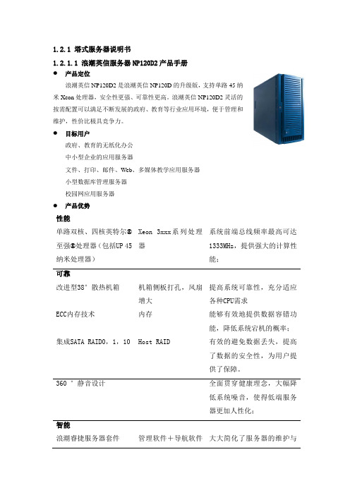
1.2.1 塔式服务器说明书1.2.1.1 浪潮英信服务器NP120D2产品手册●产品定位浪潮英信NP120D2是浪潮英信NP120D的升级版,支持单路45纳米Xeon处理器,安全性更强、可靠性更高。
浪潮英信NP120D2灵活的按需配置可以满足不断发展的政府、教育等行业应用环境,便于管理和维护,性价比极具竞争力。
●目标用户政府、教育的无纸化办公中小型企业的应用服务器文件、打印、邮件、Web、多媒体教学应用服务器小型数据库管理服务器校园网应用服务器●产品优势性能单路双核、四核英特尔®至强®处理器(包括UP 45纳米处理器)Xeon 3xxx系列处理器系统前端总线频率最高可达1333MHz,提供强大的计算性能;可靠改进型38°散热机箱机箱侧板打孔,风扇增大提高系统可靠性,充分适应各种CPU需求ECC内存技术内存能够有效地提供数据容错功能,降低系统宕机的概率;集成SATA RAID0,1,10Host RAID 有效的避免数据丢失,提高了数据的安全性,为用户提供了保障。
360 °静音设计全面贯穿健康理念,大幅降低系统噪音,使得低端服务器更加人性化;智能浪潮睿捷服务器套件管理软件+导航软件大大简化了服务器的维护与+备份还原软件管理工作,降低管理成本弹性最大6块内置硬盘机箱自带2个位置,可扩1个硬盘托架支持4个内置硬盘为用户提供足够的业务拓展空间支持传统PCI和高速PCI-E插槽保护用户现有的IT设备投资,使用户短期的投资获得更长期的超值回报。
NP120D2产品技术规格1.2.1.2 浪潮英信服务器NP370D2产品手册产品定位:浪潮英信NP370D2是一款性能卓越、安全可靠的部门级双路塔式服务器,支持Intel最新45nm双核/四核处理器,提供更优势的性能/功耗比,其灵活的按需配置即可以满足不断发展的商业应用环境,又能够为企业带来更好的经济效益。
目标用户定位在政府电子政务、中低端图形工作站、办公自动化、中小企业的应用服务器、小型数据库服务器、文件管理服务器、校园网应用服务器等。
e5ezr控制器说明书
e5ezr控制器说明书当产品在本手册描述的环境或情况下使用时,一定要遵守额定值及功能限制。
此外,为保证安全,请采用如安全安装等应对措施。
本产品应用于以下场合时须事先向弊公司洽询:使用条件及环境在本手册中未注明。
使用在核能控制、铁路、航空、车辆、焚烧装置、医疗器材、娱乐器材、安全器材等时。
使用在可能会影响人身安全或造成财产损失以及对安全性有特殊要求的场合时。
安全符号本手册使用以下符号标记E5EZ-PRR温度控制器中的安全注意事项。
这些注意事项提供了关于本产品安全应用的重要信息。
必须确保遵守所有安全注意事项中的指导。
请确保遵守以下注意事项以保证安全使用。
(1)在各型号规定的温度和温度范围内使用和储藏温控器,当二个和多个温控器水平紧靠安装或垂直紧靠安装时,由于温控器的热辐射会导致内部温度上升而降低使用寿命。
这种情况下,需要采取风扇强制冷却或其它通风措施来降低温控器的温度,但是,小心不要单冷却接线端部分以避免造成测量误差。
(2)为了不妨碍散热,温控仪周边请勿封闭。
温控仪本身的通风孔也不要堵塞。
(3)电源电压及负载,请在规格、式样范围内使用。
(4请确认端子的极性,做正确的配线。
(5)配线用压接端子请使用指定尺寸(M3.5、宽7.2mm 以下)的端子。
最大为7.5(6)配线用材料,请使用AWG24(截面积0.205mm')~AWG14(截面积2.08Imm')的电线,剥线长度:5~6mm(7)不使用的端子,请勿连接。
( 8)电源投入时,请在2秒内达到额定工作电压。
(9)可直接由前盖取出的温控仪,在取出前需先关闭电源,请绝对不要用手触摸端子或电子部品,或者给予冲击。
插回时,请不要让电子部品与外壳接触。
(10)使用自调节时,同时打开温度控制器和负载(如加热器),或在温度控制器打开前接通负载。
如果在接通负载前打开温度控制器电源,则不能再进行正确的自调节和实现最优控制。
预热完成后开始操作,预热一完成即断开电源,然后同时打开温度控制器和负载。
可编程逻辑器件APEX20K的原理及应用

可编程逻辑器件APEX20K的原理及应用1主要特点APEX20K是Altera公司生产的首款带有多核架构的可编程逻辑器件,密度在30000到1500000门,时钟速度高达822MHz。
这种多核结构克服了必须用多个器件来实现系统级设计的麻烦,同时也节省了PCB板的空间。
由于APEX20K具有功耗低、体积小、集成度高、速度快、费用低、用户可定义功能及可重复编程和擦写等许多优点,因此,可广泛应用于系统板级设计领域。
APEX20K主要特点如下:●是第一款带有多核架构的可编程逻辑器件;●内含嵌入式系统模块,并可实现多种存储器功能,其中包括先进先出存储功能(FIFO)、双口RAM、CAM(内容可寻址存储器);●密度高,门数多,逻辑元素高达51840,RAM高达442368位,基于多核的乘积项高达3456,因此可以满足系统级设计的高密度要求;●功耗低,采用1.8V-2.5V电压供电,并可与1.8V、2.5V、3.3V、5.0V供电的器件接口;图1●带有4个锁相环电路,可提供时钟锁定、时钟管理和时钟移位功能,因此可以降低时钟的延迟和抖动,并可以提供时钟的1倍至60倍的倍频与1到256的分频,可编程时钟相位和延迟相移;●具有强大的I/O功能,与PCISIG局部总线标准外设兼容,支持低压差分信号(LVDS)、LVTTL、LVCMOS、GTL、CTT、AGP、LVPECL、SSTL-3和SSTL-2及高速终端逻辑(HSTLClassI);●兼容64bit、64MHzPCI,支持PCI-X;●支持高速外部存储器,包括DDRSDRAM以及ZBTSRAM;●可在多重电压下工作,非常适合在混合电压系统中使用;●采用FineLineBGA封装,减小了芯片的占用面积,同时具有更好的温度特*;●嵌入了SignalTap的逻辑分析仪,增强了芯片的功能验**能;●支持Altera的QuartusTMII开发系统的自动布线功能。
2功能描述APEX20K系列器件将查找表逻辑和乘积项逻辑以及存储器集成在一体。
- 1、下载文档前请自行甄别文档内容的完整性,平台不提供额外的编辑、内容补充、找答案等附加服务。
- 2、"仅部分预览"的文档,不可在线预览部分如存在完整性等问题,可反馈申请退款(可完整预览的文档不适用该条件!)。
- 3、如文档侵犯您的权益,请联系客服反馈,我们会尽快为您处理(人工客服工作时间:9:00-18:30)。
Negative Value Display (Example: –18°C)
Indicates that the temperature
is below 0°C.
The E5C4 does not have a parameter display any tempera-
ture below 0°C. Therefore, the accuracy of any tempera-
ture below 0° displayed by the E5C4 cannot be guaranteed.Overflow Display
The following will be displayed if the sensor burnout detection circuit operates or the process value exceeds the temperature range that has been preset.
(Except models with a set temperature range from 0
32°F to 799
0°C to 999
or 32°F to 999
32°F to 799°F
32°F to 199°F
Operation Indicator
Indicator Output
Red
189+1 0237+1 0285+1
48 x 48
44.8 x 44.8
Dimensions with Flush-mounting Adapter (Accessory),and Back Connecting Socket (Sold Separately)
Panel Cutout
Flush-mounting adapter
Panel
Y92F-30 Flush-mounting adapter
P3G-08 Back
connecting socket
Tightening screw (96) (see note)
Note:109 mm for US08 Back Connecting Socket
60 min.
60 min.
Side-by-side Mounting of N Controllers
N 456
L
Note:
1.Recommended panel thickness is 1 to 4 mm.
2.Close side-by-side mounting is possible (in a single direction).
Accessories (Order Separately)
P2CF-08 Front Connecting Socket
Terminal Arrangement/Internal Connections (Top View)
Mounting Holes
70 max.
Eight, M3.5 x 7.5 sems
Two,4.5-dia.holes
Two, 4.5 dia. or Two, M4
50 max.
20 max.
Note:
Can also be mounted to a DIN track.
Installation
Connections
Input
Connect a thermocouple or platinum resistance thermometer to the E5C4 as shown in the following illustration.
Thermocouple input
Platinum resistance thermometer input
Voltage output (Terminal 6 is an NC terminal)
Relay output
Supply voltage 100/110, 200/220,
110/120, 220/240 VAC,50/60 Hz
Output
If the load circuit is a heating control system, be sure to connect the load to terminals 4 and 5. If the load circuit is a cooling control sys-tem, be sure to connect the load to terminals 4 and 6. If the heating control system is connected to terminals 4 and 6 or the cooling con-trol system is connected to terminals 4 and 5, the temperature of the heating control system or cooling control system will be abnormal and a serious accident may result.
If the E5C4 is in frequent operation, such as proportional operation,add an appropriate external relay to the E5C4 by considering the ca-pacity of the load and the life of the relay.
Do not ground the output of any E5C4 that has voltage output, other-wise the process temperature may not be accurate.
Power Supply
If a single power supply is used for the E5C4 and the load, the supply voltage of the power supply may vary greatly when the load is open or closed if the capacity of the power supply is not large enough.Make sure that the capacity of the power supply is large enough so that the supply voltage range will be always from 90% to 110% of the rated supply voltage.
The E5C4 operates at either 50 or 60 Hz.
Panel
Hook P2CF-08
Flush Mounting
Insert E5C4 into the square hole of the panel and insert an adapter from the back so that there will be no space between E5C4 and the panel. Then, secure the E5C4 with a screw.
Tightening screw
The P3G-08 can be wired in the same way as the P2CF-08.Temperature Setting
The leftmost digit of any E5C4 that has a set temperature range
C to 399°C will increase by 1 within a range of 0 to 3 each time the push button for the leftmost digit is pressed. The leftmost digit indicating 3 will change to 0 when the push button is pressed. Do not remove the housing of the E5C4, otherwise the housing may
To clean the surface of the E5C4, use a soft cloth wet with neutral detergent or alcohol. Do not use any organic solvent, such as paint thinner or benzine, strong acid or strong alkali to clean the surface of the E5C4, otherwise the surface of the E5C4 will become damaged.。
