SRAF890中文资料
FT890xx_普华德
on
Confidential Rev0.8 AN890xx-A0-page2
fid
en
tia
l
Fremont Micro Devices
芯片管脚说明
管脚 FT8900/ FT8901 1 2 3 / 5 6 / / FT8902 1 2 3 4 5 6 / / FT8900B/ FT8901B 3 4 / / 2 1 / 5, 6 FT8902B/ FT8902DD 7, 8 4 / 3 2 1 / 5, 6 表2 FT8900DD/ FT8901DD 7, 8 3 / / 2 1 4 5, 6
芯片版本说明
Part No. FT8900 FT8901 FT8902 FT8900B FT8901B FT8902B 调光模式 N/A 开关调光 线性调光 N/A
on
内置MOS N/A N/A N/A 650V, 2A 650V, 2A 650V, 2A 650V, 4A 650V, 4A 650V, 4A 表1
on
fid
en
tia
l
Fremont Micro Devices
Preliminary FT890xx
图8: FT8901B的典型应用图
FM
© 2013 Fremont Micro Devices Inc.
D
C
图9: FT8902B和FT8902DD的典型应用图 Confidential Rev0.8 AN890xx-A0-page6
on
图4: FT8900的典型应用图
fid
en
tia
l
Fremont Micro Devices
Preliminary FT890xx
图6: FT8902的典型应用图
RCP890A03 datasheet

SpecificationForLTCC 3dB Hybrid Coupler Model Name : RCP890A03RN2 Technologies co., Ltd.RN2 Technologies co., Ltd.284-2, Galgot-ri, Jinwe-myeon, Pyeongtaek-si, Kyunggi-do, KOREA Phone : (+82) 31 - 376 - 5400FAX : (+82) 31 - 376 - 9151 Distributor:Shenzhen Jushou electronics Co., Ltd.6F,building3,Sege science park, futian shenzhen Tel: 0086-0755-******** Mobile:0086-136******** Email: Fisher@Contact:Mr yu1. Description1-1. Part number: RCP890A031-2. Features- Hybrid Coupler 3dB, 90˚- Surface mount type- Suitable for operation frequency 815~960MHz- RoHS compliance- High stability in temperature and humidity for LTCC base - Low loss for Silver(Ag) conductor- Miniature size and high power capability- Lead-free alloy solderable- Thermal expansion corresponding with common substrate 2. Electrical SpecificationFreq. (MHz) Amplitude Balancemax (dB)Isolationmin (dB)Insertion Lossmax (dB)815-960 ±0.15 -23 -0.15VSWR MaxPhase(degrees)Power CapacityAvg. (Watt)Operating Temp.(℃)1.2 90 ±2.0 200 -55 to +1253. Mechanical Specification 3-1. Outline Dimension3-2. Weight- 1.35 Grams typical4. Port ConfigurationConfiguration Port 1 Port 2 Port 3 Port 4Case 1. Input Isolated Coupling-3dB, 0˚Output-3dB, -90˚Case 2. Isolated Input Output-3dB, 90˚Coupling -3dB, 0˚Case 3. Coupling-3dB, 0˚Output-3dB, 90˚Input IsolatedCase 4.Output-3dB, 90˚Coupling-3dB, 0˚Isolated Input * Once Port 1 is determined, the other three ports are defined automatically.5. Schematic DrawingPort1P inP cou P out P isoPort3 Port4Port26. Typical Performance Data (25℃)Return Loss [dB]Freq. [MHz]Coupling[dB]Out [dB] IL [dB]Amp.Bal.[dB]Phase[degree]S11 S22 S33 S44815 -3.12 -3.07 -0.09 ±0.02 -90.22 -26.15 -27.56 -26.33 -25.85 820 -3.11 -3.08 -0.08 ±0.02 -90.19 -26.37 -27.85 -26.56 -26.07 830 -3.11 -3.10 -0.09 ±0.00 -90.21 -26.85 -28.42 -27.07 -26.52 840 -3.09 -3.11 -0.09 ±0.01 -90.27 -27.34 -29.01 -27.61 -26.97 850 -3.09 -3.13 -0.10 ±0.02 -90.36 -27.92 -29.68 -28.18 -27.47 860 -3.08 -3.13 -0.09 ±0.03 -90.31 -28.50 -30.34 -28.82 -27.99 870 -3.07 -3.13 -0.09 ±0.03 -90.36 -29.12 -31.06 -29.44 -28.53 880 -3.06 -3.14 -0.09 ±0.04 -90.39 -29.81 -31.71 -30.12 -29.12 890 -3.07 -3.16 -0.11 ±0.05 -90.38 -30.50 -32.40 -30.84 -29.72 900 -3.06 -3.14 -0.09 ±0.04 -90.39 -31.22 -32.98 -31.48 -30.27 910 -3.06 -3.14 -0.09 ±0.04 -90.43 -31.95 -33.45 -32.22 -30.88 920 -3.06 -3.16 -0.10 ±0.05 -90.46 -32.69 -33.70 -32.94 -31.45 930 -3.06 -3.15 -0.09 ±0.04 -90.54 -33.41 -33.71 -33.55 -31.92 940 -3.07 -3.14 -0.10 ±0.04 -90.48 -34.05 -33.48 -34.03 -32.38 950 -3.07 -3.13 -0.09 ±0.03 -90.51 -34.53 -33.00 -34.41 -32.73 960 -3.08 -3.14 -0.10 ±0.03 -90.55 -34.72 -32.38 -34.50 -32.89* Data with PCB and Connector Loss ( 0.89 GHz = 0.03dB )7. Operation Temperature Curve (a)RCP650A03 Return Loss(Port1)M a g n i t u d e [d B ]Frequency[MHz]RCP890A03 Return Loss(Port2)M a g n i t u d e [d B ]Frequency[MHz]70080090010001100RCP890A03 Return Loss(Port3)M a g n i t u d e [d B ]Frequency[MHz]70080090010001100RCP890A03 Return Loss(Port4)M a g n i t u d e [d B ]Frequency[MHz]8. Operation Temperature Curve (b)70080090010001100RCP890A03 Coupling & Transmission LossM a g n i t u d e [d B ]Frequency[MHz]70080090010001100RCP890A03 Insertion LossM a g n i t u d e [d B ]Frequency[MHz]70080090010001100RCP890A03 IsolationM a g n i t u d e [d B ]Frequency[MHz]70080090010001100RCP890A03 Phase BalanceP h a s e [d e g ]Frequency[MHz]9. Test Method- Refer to ‘Case 1’ of ‘4. Port Configuration’ on page 4 - Have the network analyzer calibrated properly.- Measure the data of Coupling through port 1 to port 3. (S31) - Measure the data of Transmission through port 1 to port 4. (S41) - Measure the data of Isolation through port 1 to port 2. (S21)- Calculate the Insertion Loss and Amplitude Balance of coupler on the below power method formula.in out P cou : Power of Coupling Port P iso : Power of Isolated Port10. Measurement board layout11. Recommended PCB layout and Solder mask pattern12. Reflow profilePeakSoakingUpPre-HeatingRamp℃ T1:160±5℃ T2:180±5℃ T4:260±5℃ T3:230±5℃Temp.[]Time [sec] t1:60±5sec t2:100±15sec t3:30±5sec t4:60±10sec13. Using note for LTCC CouplersI.Be careful when transportingA.Excessive stress or shock may make products broken or cracked due to the nature ofceramics structure.B.The products cracked or damaged on terminals may have their property changed.II.Be careful during storageA.Store the products in the temperature of -55 ~ 125℃B.Keep the humidity at 45 ~ 75% around the products.C.Prevent corrosive gas (Cl2, NH3, SO X, NO X, etc.) from contacting the products.D.It is recommended to use the products within 6 months of receipt. If the period exceeds6 months, solderability may need to be verified.III.Be careful when solderingA.All the ground terminals, IN and OUT pad of coupler should be soldered on the groundplane of the PCB.B.Products may be cracked or broken by uneven forces from a claw or suction device.C.Mechanical stress by any other devices may damage products when positioning them onPCB.D. A dropped product is recommended not to be used.E.Soldering must be carried out by the condition of specification sheet.F.Any couplers which are de-soldered from PCB should not be used again.14. Packaging15. Environmental ReliabilityITEM PROCEDURE REQUIREMENTS/RESULTTemperature Cycle (Thermal Shock)1. One cycle : 30 minutesStep 1 : 125 ± 5 for 15 minutesStep 2 : -55 ± 5 for 15 minutes2. Time to approach low or high temperature: 10 seconds3. Number of Cycles : 100 cycles4. Keep normal temperature for 1 hour.1. Meet the electrical Specification after testSolderability1. Solder : 230 ± 5°C for 5± 1 sec. 1. More than 85% of the I/Oelectrode pad shall be covered with solder.Heat Resistance 1. Temperature : 100 ± 2 °C 2. Duration : 96 ± 2 hours 1. Meet the electrical Specification after testLow Temp. Resistance1. Temperature : -55 ± 5 °C2. Duration : 24 ± 2 hours 1. Meet the electrical Specification after testVibration Resistance1. Frequency: 5~ 15MHz2. Acceleration : 10g3. Sweep Time: 0.1 oct/min, 15min/axis4. Axis : X, Y and Z direction 1. No appearance damage 2. Meet the electrical Specification after testHumidity Resistance1. One Cycle :Step1:increase Temperature -25~65°C for 2hours with humidity 85%Step2:Maintain for 4 hour after increasing Humidity 90% to 95%Step3: Decrease Temperature 65°C to 25°C 2. Number of Cycles : 103. Maintain for 3hour after decreasing temperature -10°C 1. Meet the electrical Specification after testDrop Shock 1. Dropped onto hard wood from height of 50 cm for 5 times; each x, y and z direction except I/O direction.1. No appearance damage2. Meet the electrical Specification after test16. RoHS test result-RN2 Technologies warrants and represents as follows.。
YAESU FT-8900R中文说明书
YAESU FT-8900R中文说明书介绍FT-8900R是一款坚固耐用的、高质量的四小波段调频收发信机。
在29/50/144MHz段,本机提供50W的输出功率。
在430MHz 段,本机提供30W的输出功率。
FT-8900R的高功纺率输出,来源于MOSFET功率管功率放大器RD70HVF1,直吹式散热片,全自动温控式风冷散热电路。
本机有809个存储频道,全双工操作方式,独立的静噪和音量控制,内置CTCSS和DCS编/解码电路。
并有分离安装组件,使您可以将其安装到大多小型车上。
我们建议您通读本手册,以全面地了解您的FT-8900R收发信机的各种功能。
参数说明一般参数频率范围接收:20.000---29.700MHz,50.000---54.000MHz 108.800---180.000MHz,320.000---480.000MHz 700---985MHz(移动电话频率除外)发射:28.000---29.700MHz,50.000---54.000MHz 144.000---146.000MHz(或144.000---48.000MHz)430.000---440.000MHz(或430.000---50.000MHz)频道步进5/10/12/5/15/20/25/50kHz发射方式F3,F2,F1天线阻抗50欧姆,不平衡式(内置天线双工器)频率稳定度:±5ppm(-4F---+140F,或-10C---+60C)工作温度范围:-4F---+140F,或-20C---+60C 供电电压:13.8VDC(±15%),负极接地。
电流消耗(大约):接收:0.5A(静噪时)发射:8.0A(50/430MHz),8.5A(29/155MHz)外壳尺寸(宽X高X长):5.5"x1.6"x6.6(140x41.5x168mm) 重量(大约) 2.2lb(1kg)发射机参数输出功率50/20/10/5 W(29/50/144MHz) 35/20/10/5 W(430MHz)调制方式Variable Reactance最大调制频偏±5kHz带外辐射优于-69dB(29MHz段,优于-50dB)调制失真度小于3%话筒阻抗2K欧姆DA TA口阻抗10K欧姆接收机参数电路类型二次变频超外差中频频率45.05MHz/455kHz(左边) 47.25MHz/455kHz(右边)灵敏度优于0.2uV(12dB SINAD)静噪灵敏度优于0.16uV选择性12kHz/30kHz(-6dB/-60dB)最大音频输出2W,8欧姆,5% THD。
SD890A 作业指导书
SD890A 作业指导书2.换焊料b)2-9-1 Input indexer standby pos输入钩爪将LF送到给第1爪的位置c)2-9-3output indexer standby pos第4爪送到给输出钩爪的位置d)2-9-4output indexer limit pos输出爪将LF送进料盒的位置X/Y的坐标方向如下:Z(+ve)Y(+ve)X (+ve)Dispenser position fine tune1.进入2-0-0‘Edit Dispensingposition’, 根据实际的点焊料位置修改offset数值.如现在Y向的offset= -0.3mm, 而实际点焊料位置偏左0.2mm,那就需要把Dispenser 位置往右改0.2mm,将offset 设定为(-0.3+0.2)=-0.1mm. 按ESC保存数值,如果spanker 位置不需同时改动,不按1;否则按1.Spanker position fine tune2-1-7“Edit Spanking Position” 根据实际的点焊料位置修改offset 数值.如现在Y向的offset=-0.3mm, 而实际点焊料位置偏左0.2mm,那就需要把Dispenser 位置往右改0.2mm,将offset 设定为(-0.3+0.2)=-0.1mm. 按Enter保存数值,按ESC退出.按F6通过输入offset 值,修改装片位置功能快捷键说明F1:Camsel (cameral select) 装片/芯片镜头切换wafer/bondF2:PRSrch (PRS search) 芯片搜索F3:Joyspd (joystick speed) 摇竿速度切换normal/slow/fast/pitch F4:TempCtrl (temperature controller) 温度控制F5:WorkHdr (Work holder) 轨道Clear work holder LF清轨Change work holder LF data 轨道框架数据Reset all indexers复位所有钩爪Index once单步动作Bond/dispense clamp toggle开/关压板Toggle bond claw上下钩爪Move up bond claw to limit钩爪抬到最高位Move LF to dispense Posn将框架移到点焊料位置Move LF to spank Posn将框架移到压模位置Move LF to bond Posn将框架移到装片位置Change wire 换焊料Change mold 换压模块F6:BndAdj (Bond adjust) 装片位置微调F7:CamIdx (cameral index) 装片镜头移动F8:BlwCol (blow collect) 清理吸嘴Strong Blow Collet 吸嘴强吹气Change Collet 换吸嘴Pick Die Test 吸一颗芯片F9:Wafer 芯片台Change wafer换圆片Close wafer expander关闭绷环Open wafer expander开启绷环Wafer loader down once自动上片系统下一格Wafer loader up once自动上片系统上一格Move table x,y theta移动芯片台位置Align new wafer对准圆片Move to home position移到home 位Load/unload waferOn/off wafer hot blow热吹气开/关F10:Handkler 吸LF和换料盒Pick LF from stack loader 吸一条框架Reset stack loader 复位上料台Change output magazine换料盒Index output mag once料盒上一格Retard output mag once料盒下一格焊料:Pb92.5Sn5Ag2.5 直径0.5mm (常用) TO251/TO126改产品(LFand Die )LF改换相关改动1.参考温度(摄氏度)2.混合气体(L/MIN)3.调整A LF PRB 教学点焊料装置/压模/焊头高度C 调整装片位置(X,Y)DIE改换相关改动Die (mm) 3x2.5M old(mils) 167x116 Temperature Spanker (ºC) 400~420Cooling Dispenser (lpm) >10Work Holder (lpm) 25Dispensing Volume Req. (um) 2000D. Level (um) 1800/1800Wire Contact Delay(ms) 15Wire Contact Speed(u/ms) 15Wire For/Back Speed 75/75Drive In (um) 15Spanking Offset (um) -150Contact Delay perSpank (ms) 60First Soft TouchSetting(ms\um\mm/s\mm/s)40/100/40/20First spank Z Offset(um) -300Second Soft TouchSetting(ms\um\mm/s\mm/s)20/100/40/20Second spank Z Offset(um) -200 Bonding Bond Level (um)Row 1 -10Vacuum Off Delay -25Bond Delay 30Weak Blow Delay 50Pick Delay 40Arm Pick Delay 35Head Pick Delay 35Arm Bond Delay 40Head Bond Delay 35Ejector Up Delay 30Clamp Close Delay 0Soft Landing Setting OFFPick Force(g) 100Bond Force (g) 100Damping Force(g) 275Weak Blow (Mpa) 0.015TO220改产品(LFand Die)LF改换相关改动1. 参考温度(摄氏度)2. 混合气体(L/MIN)3. 调整A LF PRB 教学点焊料装置/压模/焊头高度C 调整装片位置(X,Y)DIE改换相关改动报警处理:每日维护4.对吸嘴/顶针确认,方法:a)吸嘴和顶针寿命统计和顶针孔吸嘴使用,在设定寿命限制到达时,应请相关人员确认,更换顶针后需RESET统计数;b)顶针孔是否正常,如不正常进行则予以更换,清理顶针座上的的垢物;c)使用镜子检查吸嘴是否正常,如不正常进行则予以更换5.对输入轨道的存在传感器和对准传感器光纤清理,输入轨道的清理,可用酒精棉擦拭;6.对机台进行清理每周/月维护1.正常生产中,每周清理压模2次,在更换压模前将更换和被更换的压模用刷子刷干净;2.对机台表面进行吸尘(每周),对机台运动部件进行定期清洗加油/对线路部分进行吸尘注意事项:1.在调试过程中,不得多人同时操作机台;2.在运行中,抽取料盒产品:打开安全护栏,抽取完毕,关上护栏.3.禁止在设备运行时用手或其他物件接近运动部件( 如焊头\钩爪等)4.禁止将焊料等金属物乱扔,穿完焊料,需将废焊丝回收到指定位置.6. 禁止在出料升降台堆放杂物中英文对照Die 芯片wafer 圆片magazine 料盒LF 框架collect 吸嘴Die bonder 装片机solder 焊料stack loader 上料架WH (work holder) 轨道Dispenser 点焊料装置spanker 压模装置bond 焊接optic 光学镜头bond head 焊头Wafer table 芯片台output elevator 输出升降台reset 复位Home 归位ejector 顶针器sensor 传感器indexer 步进器/勾爪Claw 钩爪wafer expander 晶片扩张器show 显示move 移动Power 电源1mm =1000um 1mil = 25.4um。
高频开关电源模块

高频开关电源模块技术手册石家庄福润新技术有限公司版权所有目录第一章概述 (3)一、简述 (3)二、模块主要特点 (3)三、型号命名 (4)四、技术指标 (4)第二章使用环境 (5)第三章模块构成 (5)一、模块的工作原理 (5)二、模块外观及外形尺寸 (6)三、模块安装 (7)四、操作说明 (11)第一章概述一、简述●我公司自主研发的FRDZ系列智能型高频开关电源,是专为电力系统设计,具有“四遥”功能的高频开关电源,模块采用世界领先的“谐振电压型双环控制的谐振开关电源技术”,具有体积小、重量轻、效率高、可靠性高等优点。
产品包括220V多个型号,配有标准RS-485接口,易于与自动化系统对接,适用于各类变电站、发电厂及水电站。
●我公司第三代(-3型)产品采用了LED数码管显示,进一步提高了产品的可靠性和美观性。
我公司-3型产品主要有以下型号:模块型号额定电压(V)额定电流(A)冷却方式外形尺寸(深×高×宽mm)FRDZ220D05Z-3 220 5 自然冷却260×179×109FRDZ220D07Z-3 220 7 自然冷却325×230×130FRDZ220D10Z-3 220 10 自然冷却325×230×130FRDZ220D20Z-3 220 20 自然冷却400×323×146二、模块主要特点●效率高,模块效率可达到95%~96%。
●重量轻,体积小。
●采用“三相无源功率因数校正电路”,输入无中线,功率因数可达0.94。
●采用隔离自主均流,并机不均流度<±3%,可保证二十台以上模块良好并机。
●模块内置直流输出隔离二极管,用户无需外设。
●模块具有RS-485接口,方便接入自动化系统进行通信。
●模块为LED数码管显示,分别设置显示切换按钮、手动调压按钮、拨码开关,操作简单。
●输出过压保护:内置过压保护电路,出现过压后模块自动锁死,模块故障指示灯亮,故障模块自动退出工作,不影响整个系统正常运行;过压保护点:220V模块为320V±5%,110V模块为160V±5%。
杭州全盛大小风电画册

009 009 010 010 011 011 014 016 017 017 018 019
中国最大的精密滑环制NTRODUCTION
杭州全盛机电科技有限公司成立于2001年,是中 国最早专业从事精密导电滑环及控制杆研发、生产、 销售的高科技企业,现拥有五十多项发明专利,填补 了国内多项空白。公司位于杭州国家级经济技术开发 区,场地面积6500余平方米,员工300余人。具有雄 厚的研发实力、一流的生产设备及高科技的加工工 艺,与国内著名的科研院所有着长期而广泛的合作, 目前是中国精密导电滑环厂家中最具规模最具实力的 企业。 公司于2008年进入风电滑环领域,产品覆盖大、 中、小风力发电领域,从100瓦到5兆瓦风机用滑 环, 产品齐全,已为国内众多知名风电厂家提供专 用风电滑环,赢得了广泛的好评。我们针对不同用户 的需求,可量身定制具体方案,同时配备了完善的售 前、售后团队,为用户提供无忧的技术服务和保障。 公司已通过欧盟CE认证、RoHS认证、国际 MSDS认证及ISO9001:2008国际质量管理体系认 证。产品覆盖全国三十来个省(自治区),并在国外 设有十多个销售机构,产品出口世界50多个国家,并 为全球知名厂家提供OEM和ODM。 Hangzhou Prosper, the earliest professional manufacturer of precision slip rings and joysticks, was established in the year of 2001, located in Hangzhou Economic & Development Area, with totally 300 employees and 6000 m2 plant area. At present, Prosper is the largest and most powerful slip ring factory in China, has more than fifty types of patented products which fill the gap in the domestic market. It has established extensive and long-term cooperation with many domestic research institutes,and owns a skilled management team, advanced technology, first-class production & inspection equipments, as well as a strict quality control system. Prosper has stepped into wind turbine slip ring industry from year 2008. The model series is complete, covering small, medium and big wind power field, ranging from 100 watts to 5 megavatts. Prosper has been supplying special slip rings to many domestic famous wind turbine manufacturers and won widespread praises. Based on the customers demands, Prosper can customize its designs and solutions. With perfect pre-sales and aftersales team, Prosper can supply with sufficient technical services and supports. Hangzhou Prosper obtains certificates of CE, RoHS, MSDS and ISO 9001-2008. Products were supplied to more than thirty provinces in domestic market. It also has over ten distributors abroad, products exported to more than 50 countries. Hangzhou Prosper is also providing both OEM and ODM services for world famous brands and customers.
ASROCK 890GM Pro3 说明书

產品摘要- 支持华擎UCC独家芯片 – CPU开核功能- 支持6核心处理器- 华擎DuraCap电容(2.5倍更长的使用寿命), 100%日本原装高品质高传导固态电容- 支持140W的CPU- 支持双通道DDR3 1800(超频)- 支持ATI™ Hybrid CrossFireX™- 集成AMD Radeon HD 4290显卡,DX10.1级别iGPU,Shader Model 4.1,最大共享显示内存512MB- 支持128MB DDR3 1333 / 1200MHz 板载显存- 多个VGA输出选项:D-Sub、DVI-D和HDMI- 1 x eSATAIII 接口, 5 x SATA3 6.0 Gb/s 接口,1 x USB 3.0 接口,2 x IEEE1394 接口- ErP/EuP Ready- 支持华擎 Instant Boot, Instant Flash, OC DNA, 华擎超频调节器, 智能型能源节约器- 7.1声道高保真音频, 支持内容保护功能, 支持DAC解码器,动态范围110分贝 (VIA® VT2020音频编码解码器具QSound功能), 支持优质蓝光音效- 附赠 : CyberLink DVD 套件 - OEM 与试用版; CreativeSound Blaster X-Fi MB - 试用版規格更改時恕不預先通知 品牌和產品名稱歸各自公司所有。
不保證任何配置与產品實物規格相同。
詳細規格中央處理器芯片內存顯卡擴充插槽音效网絡背板I/O板載接口SATA3USB 3.0BIOS特性支持光盤獨家功能附件規格尺寸認證硬件監控操作系統- Micro ATX规格:9.6英寸 x 9.0英寸,24.4厘米 x 22.9厘米- 全固态电容设计 (100%日本原装高品质高传导固态电容)- 支持 Socket AM3 处理器:AMD Phenom II X4 / X3 / X2 (除了 920 /940) / Athlon II X4 / X3 / X2 / Sempron 处理器- 支持六核心处理器- 支持 UCC 功能 (CPU开核)- V4 + 1 电源相位设计- 支持高达140W的CPU- 支持AMD Cool 'n' Quiet降温静音技术- 前端总线2600 MHz(5.2 GT/s)- 支持自由超频技术- 支持Hyper-Transport 3.0 (HT 3.0)技术- 北桥: AMD 890GX- 南桥: AMD SB850- 双通道DDR3内存技术- 4 x DDR3 内存插槽- 支持DDR3 1800(超频)/1600(超频)/1333/1066/800 non-ECC,un-buffered内存- 系统内存最大容量: 16GB- 1 x PCI Express 2.0 x 16 插槽 (蓝色: x 16)- 1 x PCI Express 2.0 x 1 插槽- 2 x PCI插槽- 支持ATI Hybrid CrossFireX- 集成AMD Radeon HD 4290显卡- DX10.1级别iGPU, Shader Model 4.1- 最大共享显示内存512MB- 支持128MB DDR3 1333 / 1200MHz 板载显存- 多个VGA输出选项:D-Sub、DVI-D和HDMI- 支持 HDMI 技术,最大分辨率达 1920 x 1200 (1080P)- 支持 Dual-link DVI,最大分辨率达 2560x1600 @ 75Hz- 支持 D-Sub,最大分辨率达 2048 x 1536 @ 85Hz- 通过 DVI 与 HDMI 端口支持 HDCP 功能- 通过 DVI 与 HDMI 端口支持1080p蓝光光盘(BD)/ HD-DVD光盘高清晰播放- 7.1声道高保真音频,支持内容保护功能- DAC解码器,动态范围110分贝 (VIA VT2020 音频编码解码器)- 支持优质蓝光音效- PCIE x 1 千兆网卡10/100/1000 Mb/s- Realtek RTL8111E- 支持网络唤醒功能(Wake-On-LAN)- 支持网线侦测- 5 x SATA3接口(6.0 Gb/s)- 1 x 红外线接针- 1 x COM端口接针- 1 x IEEE 1394接针- CPU/机箱/电源风扇接口- 24针ATX电源接口- 4针12V电源接口- 前面板音频接口- 4组USB 2.0针状接头 (支持8个USB 2.0接口)- 8Mb AMI Legal BIOS- 支持“即插即用”- 符合ACPI 1.1,支持唤醒与自动开机(Wake Up Events)- 支持免跳线- 支持SMBIOS 2.3.1- CPU VID、VCCM、NB(北桥芯片)电压多功能调节器- 5 x SATA3接口(6.0 Gb/s),支持RAID(RAID 0, RAID 1, JBOD,RAID 0+1 和 RAID 5), NCQ, AHCI和“热插拔”功能- 由 Fresco FL1000G 支持的一个 USB 3.0 端口,支持 USB 3.0,最高速度可达 5Gb/s- 驱动程序,应用软件,杀毒软件(试用版),AMD OverDrive™ 工具,AMD LIVE!™ 3D 媒体浏览器, AMD Fusion,华擎软件套装(CyberLinkDVD 套件 - OEM 与试用版; Creative Sound Blaster X-Fi MB - 试用版- 华擎超频调节器- 智能型能源节约器- Instant Boot- 华擎 Instant Flash- 华擎 OC DNA- Hybrid Booster(安心超频技术):- CPU频率无段调节- ASRock U-COP(华擎通用CPU过热保护技术)- Boot Failure Guard (B.F.G.,启动失败恢复技术)- 支持Microsoft Windows 7 / 7 64-bit / Vista / Vista 64-bit / XP /XP Media Center / XP 64-bi- FCC, CE, WHQL- 支持 ErP/EuP(需要搭配支持 ErP/EuP 的电源供应器)- 快速安装指南,支持光盘,I/O挡板- 4 x SATA数据线(选购)- CPU 温度检测- 机箱温度检测- CPU/机箱/电源风扇转速计- CPU静音风扇- 电压实时监控: +12V, +5V, +3.3V, 核心电压I/O面板- 1 x PS/2 键盘接口- 1 x VGA/D-Sub接口- 1 x VGA/DVI-D接口- 1 x HDMI接口- 1 x 光纤SPDIF数字音频输出端口- 5 x USB 2.0接口- 1 x eSATAIII 接口- 1 x USB 3.0接口- 1 x RJ-45 网卡接口LED指示灯(ACT/LINK LED和SPEED LED)- 1 x IEEE 1394接口- HD音频插孔:后置喇叭/中置/低音/线性输入/前置喇叭/麦克风USB3.0,全球使用最普遍的电脑外围接口再次迎来了重大革新,以适应目前人们对连接带宽越来越高的要求 。
af790模块参数

af790模块参数【原创实用版】目录1.AF790 模块概述2.AF790 模块主要参数3.AF790 模块应用领域正文【AF790 模块概述】AF790 模块是一款高性能、低功耗的模块,广泛应用于各种电子设备中。
它具有丰富的功能和灵活的配置选项,可以根据不同应用场景的需求进行定制。
【AF790 模块主要参数】1.工作电压:AF790 模块的工作电压范围为 3.3V-5V,适应不同设备的电压需求。
2.工作电流:模块的工作电流为 10mA-50mA,具有较低的功耗特性。
3.传输速率:AF790 模块支持高速数据传输,最高可达 480Mbps。
4.接口类型:模块提供多种接口类型,如 USB、RS485、TTL 等,方便与其他设备连接。
5.存储容量:AF790 模块内置 Flash 存储,容量为 128KB-1MB,可存储大量数据。
6.通信距离:模块支持长距离通信,最远可达 1000 米。
7.工作温度:模块的工作温度范围为 -40℃至 +85℃,适应不同环境的使用需求。
【AF790 模块应用领域】1.工业自动化:AF790 模块可应用于各种工业自动化设备,如 PLC、传感器等,实现数据采集、传输和控制功能。
2.智能家居:模块可用于智能家居设备的联网和智能化改造,如智能插座、智能灯泡等。
3.医疗设备:AF790 模块可应用于医疗设备中,实现数据传输和远程监控等功能。
4.消费电子:模块可应用于各种消费电子产品,如智能手表、智能手环等,实现数据传输和功能扩展。
5.物联网:AF790 模块可作为物联网设备中的通信模块,实现设备之间的数据传输和信息共享。
8902F1 8904F 数字电参数测量仪 使用说明书
8902F1/8904F数字电参数测量仪使用说明书(Ver2.10)青岛青智仪器有限公司地址:青岛市崂山区山东头路58号盛和大厦1号楼五层邮编:266101电话/传真:0532--81920028(多线),81920029(多线)技术热线:(0)139****0323网址: Http://目录第一章 概述 (1)第二章 主要技术参数 (2)第三章 仪器使用说明 (3)一、前面板说明 (3)二、按键功能介绍 (4)三、参数测试说明 (6)四、后面板及接线图 (6)第四章 串口通讯 (8)第五章 仪器装箱清单 (8)第六章 注意事项及故障排除方法 (9)第一章 概述8902F1/8904F数字电参数测量仪是一种利用单片机技术对信号进行分析处理的智能型仪表。
它的工作原理是:被测量的电压、电流信号首先变换成较小的电压信号,送到高速模拟数字转换器,使之转换成单片机可以处理的数字量。
单片机对采集到的数字量进行运算处理,并将最终计算的结果以数字的形式显示出来,或以串行通讯形式将数据传送给其他设备。
与传统指针式仪表相比,数字电参数测量仪具有以下优点:1.所测信号数值为真有效值。
2.直接数字显示,无读数误差。
3.对于波形失真的信号同样适用。
4.用一台仪器可以测量多个参数。
数字电参数测量仪广泛应用于电机、变电站、发电厂等测试。
仪表型号与功能的对应关系如下表所示:表1 仪表规格型号对照表型号电压、电流、有功功率、频率、功率因数电能累计RS232/RS4858902F1 √ⅹ可选8904F √ √标配RS232/ 可选RS485说明:接线方式---仪表允许的测试接线方式。
不同的接线方式对合计数据的影响见表5。
接线方式的选择依据用户的被测试设备的供电方式,或用户测试需要。
注意仪表检定时:1.电压倍率和电流倍率必须均设为1。
2.线制为三相四线,仪表接线请参照三相四线接线图。
第二章主要技术参数数字电参数测量仪的测试对象为(45~65)Hz交流信号,具体技术参数如下:1.主要技术参数:表2 数字电参数测量仪主要技术指标测量参数 测量范围 测量误差 分辨力电 压 10.0 ~ 500.0单位:V±(0.4%读数+0.1%量程) < 0.1*量程±(0.16%读数+0.04%量程) ≥0.1*量程0.1 V电 流 0.03 ~ 40.0单位:A±(0.4%读数+0.1%量程) < 0.1*量程±(0.16%读数+0.04%量程) ≥0.1*量程0.001A < 5A0.01A ≥5A有功 功率 视电压电流量程而定额定电压380V±(0.16%读数+0.04%量程) PF=1.0±(0.8%读数+0.2%量程) PF=0.50.1W <200W1W <2000W10W ≥2000W功率因数0.05~1.00 ±0.02 额定电压380V 0.01频 率 (45~65)Hz ±0.1Hz 0.1Hz以下功能仅针对8904F电 能 9999.9 MWhPF=1.0: ±(0.16%读数+0.04%量程)PF=0.5:±(0.8%读数+0.2%量程)5位数显示时 间1min~99h59min±0.05% 1分钟注1: 电压、电流允许过载为1.2倍量程上限值。
AC890PX高功率模块型AC驱动器110-400 kW(150-600 HP)说明说明书

Air Plenum
Input & Output Terminals (top power entry version)
Keypad USB Programming Port
Input Disconnect
Plug-in Modularity
• Sealed modules are easy to install and service
500mm W (79.7” H x 24.4” D x 19.7” W) enclosure
PowerPak Phase Module - Rear View
2
AC890PX
High Power Modular AC Drives
A unique high power AC drive with modular architecture
1600mm (63”) enclosure
LCL Filter
Active Bridge
Inverter
M
Power Flow
4
Specifications
Applications
OPERATING SPECS
Std Duty O/L Ratings: 110% for 60 seconds
Product Enclosure
Rating IP21/NEMA 1 standard. IP52 and higher available as special order.
Enclosure Rating
Enclosure provides 15dB attenuation to radiated emissions between 30-100MHz.
江苏思源互感器有限公司——思源电气

12
电流互感器种类
35~500kV SF6气体绝缘电流互感器
Sieyuan Electric
Copyright © Sieyuan Electric Co., Ltd. All Rights Reserved.
13
电流互感器种类
35~110kV油浸正立式电流互感器
Sieyuan Electric
Copyright © Sieyuan Electric Co., Ltd. All Rights Reserved.
2
1、公司介绍——股本结构
思源电 气75%
香港赫 兹25%
江苏思源赫兹互感器有限公司 成立于2004年8月,是由思源 电气股份有限公司与香港赫兹 有限公司双方合作,投资一亿 元人民币兴建的专业研发、生 产高压电流、电压互感器的高
Copyright © Sieyuan Electric Co., Ltd. All Rights Reserved.
17
电压互感器种类
66~500kV 配GIS用电压互感 器
Sieyuan Electric
Copyright © Sieyuan Electric Co., Ltd. All Rights Reserved.
LVB产品概述
LVB型油浸倒立式电流互感器为少油式、 全密封、免维护型产品;能够满足电力系 统客户对电流互感器越来越高的技术和性 能要求:
A、产品结构特点
B、产品的技术参数
C、产品的竞争优势
D、出厂试验严格
E、产品业绩及运行情况
Sieyuan Electric
Copyright © Sieyuan Electric Co., Ltd. All Rights Reserved.
索尼 WM-FX890随身听 说明书

To prevent fire or shock hazard, do not expose the unit to rain or moisture.
Do not install the appliance in a confined space, such as a bookcase or built-in cabinet.
• Do not place the unit on the charging stand without the rechargeable battery. Otherwise, this may cause malfunction.
When to replace/ charge the battery C
Tape playback
30
Radio reception
34
Sony alkaline LR6 (SG)** and Rechargeable NH-14WM (A)
Tape playback
80
Radio reception
90
* Measured value by the standard of JEITA (Japan Electronics and Information Technology Industries Association). (Using a Sony HF series cassette tape)
** When using a Sony LR6(SG) alkaline dry battery (produced in Japan).
Notes
• The battery life may be shorter depending on the operating condition, the surrounding temperature and battery type.
A119-890 系列数字式万用表用户手册说明书

1A119-890系列数字式万用表用户手册目录一、概述二、安全事项三、特性四、操作说明五、维护保养0六、故障排除1一、概述2A119-8900系列仪表是一种性能稳定,用电池驱动的高可靠性数字万用表.仪表采用大屏幕LCD 显示器,加上靓丽的背景光(仅限38900系列)使显示清晰美观,更加使用方便。
4此系列仪表可用来测量直流电压和交流电压、直流电流和交流电流、电阻、电容、二极管、三极管、通断测试、温度、火线识别(仅5限9200系列)。
整机以高精度低噪音A/D 转换器为核心,搭载内部数字处理器可以做到2kHz 频率带宽数字平均值测量,是一台性能优6越的工具表,是实验室、工厂无线电爱好者及家庭的理想工具。
7二、安全事项8本系列仪表设计符合IEC1010的相关条款。
使用之前,请仔细阅读说明书。
91.使用前应检查确认仪表无破损,表笔和表笔线的绝缘层完好。
2.手握表笔时,应特别注意手不能超过测试针根部挡位塑胶突起,否则有电击的危险。
13.打开后盖更换电池前,须拔去表笔;合上后盖并旋紧螺钉后,才能进行测量,否则有受电击的危险。
24.测量过程中需切换,要先断开仪表输入后再旋转功能/量程开关。
35.输入信号电压不允许超过规定的极限值。
46.测量公共端“COM”和“大地”之间的电压不得超过1000V,以防电击和损坏仪表。
57.被测电压高于DC60V 和AC42V 的场合,均应小心谨慎,防止电击。
68.液晶显示“”符号时,表示电池电压不足,应及时更换电池,以确保测量准确度。
79.仪表内保险丝的更换应采用同类型规格。
具体规格见维护保养中的条款或机板上的标注。
810.安全符号说明:9直流交流电池不足0警告提示双重绝缘高压危险三、特性1.一般特性①.显示:a.大屏幕液晶显示:可视区61×32mm、字高25mm;b.最大显示值: (31/2位);c.全功能、单位符号显示;d.自动极性显示、超量程显示“OL”、低压电池更换显示“”;e.小功耗亮丽背景光,数秒钟自动熄灭。
Furukawa OFS 200

For Use With:200 µm ST and SMA Factory5 Termination Kits200 µm HCS ® Factory5 Fiber-Optic Cable ST and SMA Factory5 Crimp & Cleave ConnectorsCrimp & Cleave Termination Instructionsfor 200 µm Factory5 Cable with ST and SMA ConnectorsPlease Read FirstPlease make sure to READ and understand t ermination in-structions completely. Improper a ssembly will cause poor termination results and cause damage to termination kit com-ponents.Make sure you WEAR eye protection during the c leaving process. The bare fiber is sharp and may s plinter; handle very carefully. Make sure fiber is d isposed of properly, in a hard-sided container.OFS WARRANTS this t ermination kit to be free of defects for a period of 90 days from the date of purchase. Each kit is q ualified at our factory prior to shipment. OFS will, at their discretion, repair or replace any tools found to be defec-tive due to workmanship within the stated warranty period. (Excludes damage to the fiber stripper, cleave tool, and/or d iamond blade due to m isuse.)OFS recommends that all replacements or repairs be made at our manufacturing facility, except where specifically out-lined. Please C ONTACT the sales representative in your re-gion or call the factory for technical support:Monday-Friday, 8:00 am-5:00 pm EST.888-438-9936 [Toll free in the US and Canada]860-678-0371[International]Important Safety and Warranty Information888 438 9936 (US & Canada) or 860 678 0371 | iContent Page Factory5 ST and SMA Termination Kit Contents (1)Related Products and Accessories......................2-3 Factory5 ST and SMA Connectors (4)Termination InstructionsStep 1: Install strain relief boot (5)Step 2: Strip cable outer jacket ......................6-7 Step 3: Strip sub-unit outer jacket ....................8-9 Step 4: Strip fiber buffer..........................10-11 Step 5: Install cable anchor .. (12)Step 6: Install crimp sleeve .......................13-14 Step 7: Install ferrule . (15)Step 8: Crimp ferrule ............................16-18 Step 9: Cleave fiber .............................19-21 Step 10: Position strain relief boot ..................22-23 Diamond Cleave Tool Diagram .........................19Content Page Maintenance & Trouble Shooting GuideImportance of Cleave Tool Cleaning and Maintenance (24)Cleave Tool Cleaning Kit (24)Diamond Blade Replacement Kit (24)Trouble Shooting Guide (25)Termination and Test Kits Available (26)Trademark Information.........................Back Cover Table of ContentsFinal AssemblyFiber StripperBrushProng ToolScissorsCrimp ToolCable StripperDiamond CleaveToolFactory5 ST and SMA Termination Kit Contents888 438 9936 (US & Canada) or 860 678 0371 | 12 ST and SMA Termination Kit Contents continuedCP01229-02...........200 µm Fiber Stripper (White Blade Insert)with Cleaning Brush and Prong ToolAP01225.........................................ScissorsK16248.....................Booklet: Importance of Cleave ToolCleaning and MaintenanceOther Items Required (not included in kit): Safety Glasses, Marker3888 438 9936 (US & Canada) or 860 678 0371 | Termination kit contentscontinues onto the next pagePart Numbers DescriptionBT01827...............................SMA Positioner Plate (use to convert an ST kit to an SMA kit)BT01900................................ST Positioner Plate (use to convert an SMA kit to an ST kit)P10188-03 ........................Insertion Loss Test Kit for 200 µm ST Connectors P10188-05 ........................Insertion Loss Test Kit for 200 µm SMA Connectors P10188-08 ........................Insertion Loss Test Kit for 200 µm ST, SMA, V-Pin, and F07 Connectors P16247 ...........................Cleave Tool Cleaning Kit (Includes cleaning fluid and safe cleaning swabs)AT03290 ....................Diamond Blade Replacement KitNOTE:Only one component part replacement isrequired to convert an ST Termination Kit to its same size equivalent SMA TerminationKit and vice versa.Factory5 ST and SMA ConnectorsDescription Part NumbersSMA Connectors ..................................P18241ST Connectors ....................................P18242ST ConnectorBoot AnchorCrimp SleeveFerruleCapSMA ConnectorTermination InstructionsInstall Strain Relief Boot• S lide STRAIN RELIEF BOOT onto cable and move up andout of the way for easystripping.888 438 9936 (US & Canada) or 860 678 0371 | 56 Termination InstructionsSTEP2Strip Cable Outer Jacket• M ark cable outer jacket 3/4 inchesfrom the end with a marker.• S elect the 3.2 hole on the Cable Jacket Strip Toolto strip Cable Outer Jacket31/4”888 438 9936 (US & Canada) or 860 678 0371 | 7• V erify proper strip length against the strip template shown below.• C arefully unravel the aramid braid with a pointed instrument.• W hen the yarns are unravelled,cut them as closely to the cable outer jacket as possible.Slide scissors or other pointed object in this direction, carefully unravelling as many yarns at a time as is manageable withoutc reating a knot.88 Termination Instructions• S trip jacket using the 1.6 hole using the CABLEJACKET STRIP TOOL, apply a quick-but-partialsqueezing action (fully compressing the handles willcause the tool to incorrectly snap onto the fiber, possiblybreaking it), release and removethe outer jacket.3/4”• V erify proper strip length against thestrip template shown on page 7.888 438 9936 (US & Canada) or 860 678 0371 | 9Termination Instructions10NOTE:Be careful not to touch the HCS fiber coating once the fiber has been stripped. The coating will retain finger oils which can transfer to and damage the gripper pads in the cleaver during Step 9 in the termination process.STEP4Strip Fiber Buffer B efore you start:B e careful while handling the FIBER STRIPPER. Handle as a p recision device and do not strike on hard surfaces or drop.B e sure to clean blades frequently using small bristle brush sup-plied.IMPORTANT: Pull straight when stripping the fiber buffer. The HCS fiber cladding can be damaged if fiber is not pulled straight.• S eparate buffered fiber from yellow aramid yarn by pulling yarn back along the cable.NOTE:If unable to insert buffered fiber throughguide tube, trim tip of the fiber using scis-sors.NOTE:If a short length of cable is being termi-nated, wrap the cable around your hand to prevent fiber and aramid yarn from pulling out of cable.888 438 9936 (US & Canada) or 860 678 0371 | 11• I nsert the buffered fiber through the guide tube of the fiber stripper until the sub unit outer jacket b ottoms out inside the tube.• H olding cable securely, squeeze handles to cut buffer and PULL STRAIGHT to remove buffer.• I nspect HCS cladding for damage from improper buffer stripping. (i.e. white dusty stripe)• V erify proper buffer strip length against the strip template shown on page 7.NOTE:If damage is visible cut off the damagedfiber and repeat the procedure from Step 2: Strip Cable Outer Jacket.A p p r o x ima t e ly 1/8”M a x im u m 1/4”Termination Instructions12Install Cable Anchor• P ull aramid yarn strands back over stripped fiber.• H olding aramid yarn and fiber at very top. Feed the fiber and the aramid yarn through the CABLE ANCHOR. Bottom out the anchor on the cable sub-unit outer jacket using a clockwise turning motion. (i.e. screw the anchor onto the cable outer jacket, if n ecessary)• P osition anchor in CRIMP TOOL,centering the rear end of the anchor in the crimp nest.• S queeze crimp tool handles together until it clicks, then releases.STEP5NOTE:Be careful not to touch the HCS fiber coat-ing once the fiber has been stripped. The coating will retain finger oils which can transfer to and damage the gripper pads in the cleaver during Step 9 in the terminationprocess.888 438 9936 (US & Canada) or 860 678 0371 | 136Install Crimp Sleeve• D ivide the aramid yarn into approximately two equal halves.• F old both halves of the aramid yarn back over the cable an-chor. Be sure the fiber is centered in the cable anchor.• S lide the CRIMP SLEEVE over the cable anchor and aramid yarn until it bottoms out on the cable anchor.Step 6 continues onto the next pageCrimp from Step 5: Note position of aramid yarns in relation to this crimp. Maintain this position here and in Step 7.Termination Instructions14Install Crimp Sleeve continued• P osition the crimp sleeve in the CRIMP TOOL such that:• Squeeze crimp tool handles together.~ T he back edge of the crimp sleeve is aligned with the edge of the crimp nest.~ T he aramid yarn halves are positioned over thejaws.Crimp from Step 5: Note that the orientation of ar-amid yarns is maintained in relation to the jaws ofthe crimp tool.7Install Ferrule• F eed fiber through hole in rear of FERRULE.• S lide the ferrule for either SMA or ST connector down thefiber and into the crimp sleeve. Rotate to the o rientationshown below. Push the ferrule firmly until it bottoms out inthe crimp sleeve.SMA shown in illustrationKeyST shown in illustration888 438 9936 (US & Canada) or 860 678 0371 | 1516 Termination InstructionsSTEP8Crimp FerruleB efore you start:Make sure the ferrule is fully seated in the crimp sleeve.C heck to make sure the crimp die set is stamped properly for theconnector type, ‘SMA’ on one side and ‘ST’ on the other.P roper positioning of the connector in the die set is critical for aproper crimp location. Failure to crimp in the prescribed locationwill result in poor connector retention strength.C rimp dies can be reversed at the factory for left-handed opera-tors.SMA Connector• P osition the back of the SMA COUPLING NUT against the side of the crimp die set stamped‘SMA’ as shown.• R otate the SMA connector so that its l ocation dimple is oriented in the crimpdie set as shown.• S queeze CRIMP TOOL handles togetheruntil the tool releases.Step 8 continuesonto the next page17888 438 9936 (US & Canada) or 860 678 0371 | Termination Instructions18Crimp Ferrule continuedST Connector• P osition the back of the ST COUPLING NUT against the side of the crimp die set stamped ‘ST’.• R otate the ST connector so that its keyis oriented in the crimp die set as shown.• S queeze CRIMP TOOL handles together untilthe tool releases.KeywayKeywayTension SpringGripper PadsDiamond Blade & Anvil HousingPositioner PlateTrigger9Cleave Fiber B efore you start:Make sure the appropriate cleave tool positioner plate is beingused: SMA or STM ake sure the appropriate colored tension spring is being used: 200 µm = GREENR efer to diagram of the Cleave Tool.C areful while handling the Cleave Tool. Handle as a p recision de-vice and do not strike on hard surfaces or drop.K eep the cleave tool clean and free from oils, including naturally oc-curing finger oils. Gripper pads, diamond blade and anvil should be cleaned after every 50 cleaves. Use the OFS Cleave Tool Cleaning Kit — Part #P16247 - available separately.D o not use alcohol to clean the diamond blade or the gripper pads. Al-cohol will chemically react with the gripper pads and ruin them.D o not insert metal tools near the diamond blade, as it is fragile andmay chip.888 438 9936 (US & Canada) or 860 678 0371 | Step 9 continues onto the next page19Termination Instructions20NOTE:It is critical to fully insert the connector into the positioner plate. Failure to do so, may cause poor cleave quality and/or damage to the diamond blade.NOTE:Do not hold onto the connector during thecleave process. Doing so may cause poor cleave quality.STEP9Cleave Fiber continued• H olding the CLEAVING TOOL in a horizontal position, grip the handle while leaving your index finger free to actuate trig-ger.• P lace the ferrule into the hole of the positioner plate until it is fully inserted.• R elease the connector in the tool.• U sing index finger, slowly and gently depress trigger to perform the cleaveprocess. The cleave process is complete when the fiber snaps away from theconnector. Do not release trigger!• B efore releasing the trigger, remove the connector from the cleave tool andgrasp the top of the scrap fiber while releasing the trigger. Gently remove thescrap fiber while keeping it away from the diamond blade.• D ispose of scrap fiber safely in a hard-sided container.• I nstall protective cap onto connector to protect cleaved fiber surface.21888 438 9936 (US & Canada) or 860 678 0371 | 22 Termination InstructionsSTEP10Position Strain Relief Boot• U sing scissors, trim exposed aramid yarn as close to crimpsleeve as possible.• S lide strain relief boot onto connector (up to rear of couplingnut) to complete termination.888 438 9936 (US & Canada) or 860 678 0371 | 23Maintenance & Trouble Shooting GuideImportance of Cleave Tool Cleaningand MaintenanceThe Cleave Tool supplied with OFS’s Termination Kits con-tains movable parts, wear items, and a diamond blade that require regular maintenance, care, or replacement after useful life in order to perform satisfactorily. Damage and parts re-placement expense can result if recommended procedures are not followed.~T he diamond blade must be cleaned; the gripper pads must be cleaned, kept oil-free, and replaced after wear.~ The cleave-tool trigger must be depressed slowly.Cleave Tool Cleaning KitFor cleaning your cleave tool, please order the OFS Cleave Tool Cleaning Kit (part #P16247) which includes recom-mended cleaning fluid, swabs, and c omplete instructions. Diamond Blade Replacement KitFor replacing the diamond blade/anvil assembly, please order the Diamond Blade Replacement Kit (Part #AT03290.)The kit includes a new diamond blade, anvil, replacement screws, and complete instructions for performing this simple proce-dure at your facility.24Trouble Shooting Guide888 438 9936 (US & Canada) or 860 678 0371 | 2526 Termination and Test Kits AvailableOFS offers a specialized Termination Kit—and a ssociatedInsertion Loss Test Kit—for each type of Crimp &Cleave connector we support. These kits are availablein various combinations of sizes and/or connector types.Customer Relations at our factory can help you select thecorrect kit for your purposes.This document is for informational purposes only and is not intended to modify or supplement any OFS warranties or specifications relating to any of its products and services.Copyright © 2014 OFS Fitel, LLC.All Rights Reserved.081455 Darling Drive, Avon, CT 06001To learn more, please call or visit our website. Phone: 186****0371Toll Free: 188****9936Web: P18225 Rev. E Trademark Information:Manufactured in the USA by OFS.HCS is a registered trademark in the USA of OFS Fitel, LLC.。
阿富汗电气AF80-30-00-13电源接触器说明书

Object Classification Code ETIM 4 ETIM 5 ETIM 6 ETIM 7 UNSPSC E-Number (Sweden)
— Container Information
Package Level 1 Units Package Level 1 Width Package Level 1 Depth / Length Package Level 1 Height Package Level 1 Gross Weight Package Level 1 EAN Package Level 2 Units Package Level 2 Width Package Level 2 Depth / Length Package Level 2 Height Package Level 2 Gross Weight Package Level 3 Units
ABS_15-GE1349500-PDA_90682247 BV_2634H36994A CB_SE-77417M1 CCC_2013010304646569 1SBD250000U1000 DNV-GL_TAE00001AF-3 DNV-GL_TAE00001AF-3 EAC_RU C-FR ME77 B03597 1SBD250168E1000 DNV-GL_TAE00001AF-3 1SBC101036M6801 KC_HW02016-15011A LRS_1300087E1 RINA_ELE084013XG RMRS_1802705280 1SBD250000U1000 UL_20130926-E312527_14_1 UL_E312527
(220 / 230 / 240 V) 22 KWT (380 / 400 V) 37 KWT (415 V) 45 KWT (440 V) 45 KWT (500 V) 45 KWT (690 V) 45 KWT (400 V) 37 KWT
ra8900ce备用电源参数

ra8900ce备用电源参数RA8900CE是一款备用电源,具有以下参数和特点:1.输入电压范围广泛:RA8900CE备用电源的输入电压范围为85至264VAC,适用于全球各地区的电网标准。
无论在发达国家还是发展中国家,都可以提供稳定可靠的电源支持。
2.输出电压可调节:RA8900CE备用电源的输出电压可以通过调节器进行调节,范围为1.0V至54.0V,可满足不同设备的电压需求。
无论是低压设备还是高压设备,RA8900CE备用电源都可以提供稳定的输出电压。
3.高效率:RA8900CE备用电源采用先进的开关电源技术,具有高效率和低功率损耗的特点。
在正常工作状态下,其效率可高达90%以上,能够最大程度地减少能源浪费,节省电费支出。
4.大容量:RA8900CE备用电源的电源容量可根据需求进行定制,通常有多种不同的容量可供选择。
从小型家用设备到大型工业设备,RA8900CE备用电源都可以提供足够的电力,确保设备的正常运行。
5.可靠性高:RA8900CE备用电源采用了优质的电子元件和稳定的电路设计,具有高度的可靠性。
在设计和生产过程中,严格遵循国际标准和质量管理体系,确保每一台备用电源的性能稳定可靠。
6.全面的保护功能:RA8900CE备用电源具有全面的保护功能,可保护设备免受电压过载、短路、过流等电力问题的影响。
同时,也具有温度过高、过热等故障保护功能,有效延长设备的使用寿命。
7.友好的人机界面:RA8900CE备用电源采用直观的人机界面设计,操作简便,便于用户进行设备的设置和监控。
配备LCD显示屏和按键,用户可以直观地了解备用电源的工作状态和参数。
8.多种输出接口:RA8900CE备用电源具有多种输出接口,包括DC接口、USB接口和交流输出接口等,可以满足不同设备的接口需求。
无论是充电器、电子设备还是工业设备,都可以与RA8900CE备用电源进行连接和使用。
总结起来,RA8900CE备用电源具有输入电压范围广泛、输出电压可调节、高效率、大容量、可靠性高、全面的保护功能、友好的人机界面和多种输出接口等特点。
映泰科技890FX Deluxe3说明书

Asrock 890fx e 3. Asrock 890fx deluxe4.
CPU II X6 is a six-core support (processor unlocked) Asrock Dancap (2.5 x Lift Lift), 100% Japan made high-quality cordy cordy thermal capacitors polymer, supports ATI Quad Crossfirex, 3 and compared Crossfirex Crossfire x ¢ 1 ESATA3, 8 SATA3 , 4 USB 3.1 Gen1 Smart Switch Design: 1 LED Power Switch, 1 SMOP Switch with LED, 1 Clear CMOS Switch with iStant Buot, Instant Flash, OC, IS, DNA, Multi Speed Fan, Multi Speed Fan, Multi Speed Fan 7.1 Audio ch audio o. HD with content protection, DAC with dynamic range of 110 dB (Via VT2020 Audio Codec), Blu-ray Premium ERP/EUP Free Software Audio: Cyberlink DVD-Suite-Om tests; Creative Sound Blaster X -fi MB - This model cannot be sold worldwide. Contact your local dealer for availa
ft-8900说明书
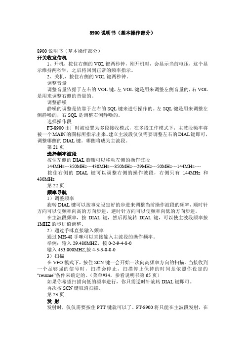
8900说明书(基本操作部分)8900说明书(基本操作部分)开关收发信机1、开机,按住右侧的VOL键两秒钟,刚开机时,会显示当前电压,这个显示维持两秒钟,之后将回到正常的频率指示。
2、关机,按住右侧的VOL键两秒钟。
调整音量调整音量依据于左右的VOL键,左VOL键是用来调整左侧音量的,右VOL 是用来调整右侧的音量的。
调整静噪静噪的调整是依靠于左右的SQL键来进行操作的。
左SQL键是用来调整左侧静噪的,右SQL是调整右侧静噪的。
选择操作段FT-8900出厂时被设置为多段接收模式,在多段工作模式下,主波段频率将被一个MAIN的图标所指示出来。
建立主波段仅仅需要调整左右的DIAL键即可,调整哪侧的DIAL键。
哪侧将成为主波段。
第21页选择频率波段按住左侧的DIAL旋钮可以移动左侧的操作波段144MHz---350MHz---430MHz---850MHz---29MHz---50MHz---144MHz----按住右侧的DIAL键可以调整右侧的操作波段,右侧只有144MHz和430MHz第22页频率导航1)调整频率旋转DIAL键可以按事先设定好的步进来调整当前操作波段的频率,顺时针方向可以使频率向高的方向步进,逆时针方向可以使频率向低的方向步进。
在主波段频率,按DIAL键,然后再旋转DIAL键,可以使主波段频率按1MHZ的步进值调整。
2)通过手咪直接输入频率通过MH-48手咪可以直接输入主波段的操作频率。
举例:输入29.480MHZ,按0-2-9-4-8-0输入433.000MHZ,按4-3-3-0-0-03)扫描在VFO模式下,按住SCN键一会开始一次向高频率方向的扫描。
当接收到一个足够强的信号时,扫描会停止,扫描停止保持的时间是依照你设定的“resume”条件来确定的。
(菜单#34,参看说明书第65页)如果你希望扫描向低的频率进行,你只需逆时针旋转DIAL键即可。
再次按SCN键取消扫描。
第23页发射发射时,仅仅需要按住PTT键就可以了。
- 1、下载文档前请自行甄别文档内容的完整性,平台不提供额外的编辑、内容补充、找答案等附加服务。
- 2、"仅部分预览"的文档,不可在线预览部分如存在完整性等问题,可反馈申请退款(可完整预览的文档不适用该条件!)。
- 3、如文档侵犯您的权益,请联系客服反馈,我们会尽快为您处理(人工客服工作时间:9:00-18:30)。
FIG.2- TYPICAL REVERSE CHARACTERISTICS
10
AVERAGE FORWARD CURRENT. (A)
SRAF850-SRAF8100 8
0 0C Tj=10
6 SRAF820-SRAF840 4
INSTANTANEOUS REVERSE CURRENT. (mA)
元器件交易网
SRAF820 THRU SRAF8100
Isolation 8.0 AMPS. Schottky Barrier Rectifiers
Voltage Range 20 to 100 Volts Current 8.0 Amperes
Features
Low forward voltage drop High current capability High reliability High surge current capability
AF
85
0SR
AF
AF
86
1
2
5
10
20
50
100
0
10
AF
25
84
0
JUNCTION CAPACITANCE.(pF)
2000
1.0
S
F RA
890
-SR
AF
8 10
0
1000 800 600 400
SR
AF8
20-
SR
AF8
40
Tj=25oC Pulse Width=300 s 1% Duty Cycle 0.1 0.1 0.2 0.3 0.4 0.5 0.6 0.7 0.8 0.9
.161(4.1) .146(3.7)
.110( 2.8) .0 98(2 .5)
. 071 (1. 8) MA X
. 543( 13. 8) . 512( 13. 2)
2
. 10 0( 2 . 55)
. 100 (2.5 5)
Dimensions in inches and (millimeters)
SR
AF8
50SR
AF8
100
200
100 0.1
FORWARD VOLTAGE. (V) 0.4 1.0 4 10 REVERSE VOLTAGE. (V) 40 100
- 121 -
. 606(1 5.5 ) . 583(1 4.8 )
Mechanical Data
.0 63 (1 .6 ) MA X
Cases: ITO-220AC molded plastic Epoxy: UL 94V-O rate flame retardant Terminals: Leads solderable per MIL-STD-202, Method 208 guaranteed Polarity: As marked High temperature soldering guaranteed: 260OC/10 seconds/.25”,(6.35mm) from case. Weight: 2.24 grams
VRRM VRMS VDC I(AV) IFSM VF IR
RθJC
820 20 14 20
830 30 21 30
840 40 28 40
850 50 35 50 8.0 150
860 60 42 60
890 90 63 90
8100 100 70 100
V V V A A
0.55
0.70 0.5 50 5.0
Maximum Ratings and Electrical Characteristics
Rating at 25℃ambient temperature unless otherwise specified. Single phase, half wave, 60 Hz, resistive or inductive load. For capacitive load, derate current by 20% Symbol SRAF SRAF SRAF SRAF SRAF SRAF SRAF Units Type Number
.124(3.16) .118(3.00)
ITO-220AC
.185(4.7) .173(4.4)
.406(10.3) .390(9.90) .13 4(3. 4)D IA . 11 3(3. 0)D IA . 112 (2. 85) . 100 (2.5 5)
.2 72( 6. 9) .2 48( 6. 3)
TJ
Cj
430 -65 to +125
V mA mA ℃/W pF ℃ ℃
- 120 -
元器件交易网
RATINGS AND CHARACTERISTIC CURVES (SRAF820 THRU SRAF8100)
FIG.1- MAXIMUM FORWARD CURRENT DERATING CURVE
125
100
FIG.5- TYPICAL FORWARD CHARACTERISTICS
50
50
INSTANTANEOUS FORWARD CURRENT. (A)
0SR
82
NUMBER OF CYCLES AT 60Hz
SR
4000 Tj=25 0C
SR
FIG.4- TYPICAL JUNCTION CAPACITANCE
1
Tj=75 0C
0.1
2
0
0
50
100
o
150
CASE TEMPERATURE. ( C)
0.01
FIG.3- MAXIMUM NON-REPETITIVE FORWARD SURGE CURRENT
175
Tj=25 0C
PEAK FORWARD SURGE CURRENT. (A)
150
8.3ms Single Half Sine Wave JEDEC Method 0.001 20 40 60 80 100 0 120 PERCENT OF RATED PEAK REVERSE VOLTAGE. (%) 140
0.75
360 -65 to +150 Storage Temperature Range TSTG -65 to +150 Notes: 1. Thermal Resistance from Junction to Case Per Leg with Heat sink (2”x3”x0.25”) Al-Plate. 2. Measured at 1MHz and Applied Reverse Voltage of 4.0V D.C.
Maximum Recurrent Peak Reverse ltage Maximum RMS Voltage Maximum DC Blocking Voltage Maximum Average Forward Rectified Current See Fig. 1 Peak Forward Surge Current, 8.3 ms Single Half Sine-wave Superimposed on Rated Load (JEDEC method ) Maximum Instantaneous Forward Voltage @8.0A Maximum D.C. Reverse Current @ Tc=25℃ at Rated DC Blocking Voltage @ Tc=100℃ Typical Thermal Resistance (Note 1) Typical Junction Capacitance (Note 2) Operating Junction Temperature Range