STM1813中文资料
DATASENSOR 带背景抑制的M18光电传感器 说明书
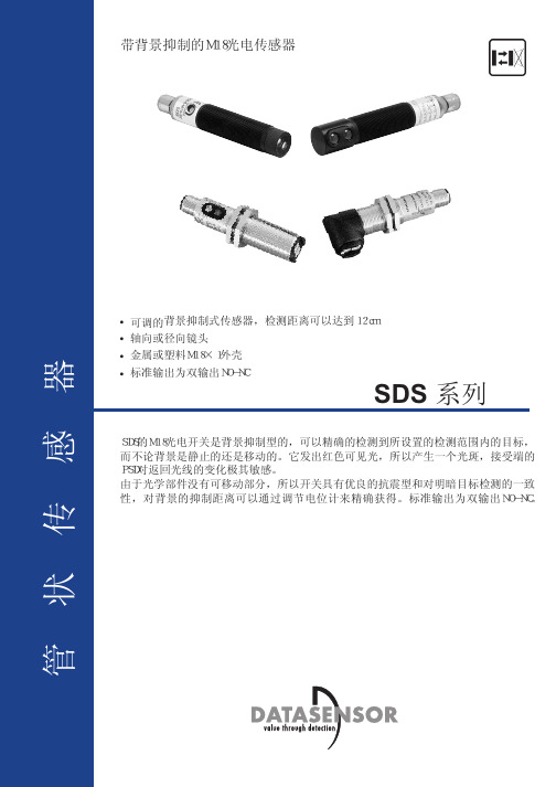
技术参数 性能曲线工作电压:...............................................10...30 Vdc, reverse polarity protection 功耗:...............................................30 mA max. 发射光:.............................................red LED 660 nm 光斑尺寸:...........................................Ø 10 mm at 100 mm Ø 15 mm at 100 mm (SDS5 radial vers.)背景抑制距离: .....2 ...10 cm ( SDS5 vers.)4 ...12 cm (SDS10 vers.)调整方式:..........................................................multi-turn trimmer指示:.....................................................yellow OUTPUT LEDgreen STABILITY LED (SDS5 vers.)输出类型:..................................................NO-NC PNP or NPN, open collector 饱和电压:.......................................2 V max. (SDS5 PNPvers.)1 V max. (SDS5 NPN vers.)2.4 V max. (SDS10 vers.)输出电流:.............................................100 mA max. (SDS5 vers.)200 mA max. (SDS10 vers.)short-circuit protection反应时间:.............................................2.5ms max. (SDS5 vers.)1 ms max. (SDS10 vers.)开关频率:...................................200 Hz max. (SDS5 vers.)600 Hz max. (SDS10 vers.)工作模式:...........................................light (NO)dark (NC)接线方式:..................................................M12 4-pole connector3 m Ø 5 mm cable (SDS10 vers.)电气保护等级 :....................................class 2外壳防护等级:................................IP67外壳材料:.........................................ABS (SDS5 vers.)nickel-plated brass (SDS10 vers.)镜头材料:...............................................glass重量:..........................................................30 g max. (SDS5 vers.)100 g max. (SDS10 cable vers.)30 g max. (SDS10 connector vers.)工作温度:...............................-25...+55°C 储存温度: ...................................-25 ...+70°C 参照标准:...................................EN 60947-5-2认证证书 :...............................................The operating distances indicate the detection distance with excess gain 2.SDS5-x-MGrey R18%White R90%The detection diagrams indicate the typicaloperating distance with excess gain 1.SDS10-x-MWhite 90%Grey 18%mmNC OUTPUT NO OUTPUT24242424SDS10 尺寸图SDS10-5-M12-35SDS10-5-M12-30AXIALSDS10-5-M12-37SDS10-5-M12-32RADIALOUTPUT LED STABILITY LEDOUTPUT LED STABILITY LED。
1N18中文资料

FIG.3-TYPICAL INSTANTANEOUS FORWARD CHARACTERISTICS
FIG.4-TYPICAL REVERSE CHARACTERISTICS
IN STAN TANEOUS FORWARD CURRENT( AMPERES)
TJ=125 C
PULSE WIDTH=300 S 1% DUTY CYCLE
Maximum Ratings
• • • • Operating Temperature: -55°C to +125°C Storage Temperature: -55°C to +125°C Typical Thermal Resistance: 50oC/W junction to Ambient For capacitive load. Derate current by 20% Maximum Recurrent Peak Reverse Voltage 20V 30V 40V Maximum DC Blocking Voltage 20V 30V 40V
RESISTIVE OR INDUCTIVE LOAD 0.375" (9.5MM) LEAD LENGTH
PEAK FORWARD SURGE CURRENT(AMPERES)
LEAD TEMPERATURE ( C)
NUMBER OF CYCLES AT 60Hz
JUNCTION CAPACITANCE(pF)
TJ=25 C f=1.0MHZ
Vsig=50mVp-p
18 mm传感器数据手册说明书
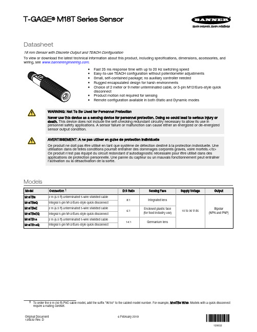
Datasheet18 mm Sensor with Discrete Output and TEACH ConfigurationTo view or download the latest technical information about this product, including specifications, dimensions, accessories, and wiring, see .•Fast 25 ms response time with up to 20 Hz switching speed•Easy-to-use TEACH configuration without potentiometer adjustments •Small, self-contained package; no auxiliary controller needed •Rugged encapsulated design for harsh environments•Choice of 2 meter or 9 meter unterminated cable, or 5-pin M12/Euro-style quick disconnect•Product motion not required for sensing•Remote configurationavailable in both Static and Dynamic modesWARNING: Not To Be Used for Personnel ProtectionNever use this device as a sensing device for personnel protection. Doing so could lead to serious injury or death. This device does not include the self-checking redundant circuitry necessary to allow its use inpersonnel safety applications. A sensor failure or malfunction can cause either an energized or de-energizedsensor output condition.AVERTISSEMENT: A ne pas utiliser en guise de protection individuelleCe produit ne doit pas être utilisé en tant que système de détection destiné à la protection individuelle. Une utilisation dans de telles conditions pourrait entraîner des dommages corporels graves, voire mortels.</b>Ce produit n'est pas équipé du circuit redondant d'autodiagnostic nécessaire pour être utilisé dans desapplications de protection personnelle. Une panne du capteur ou un mauvais fonctionnement peut entraîner l'activation ou la désactivation de la sortie.ModelsT-GAGE ® M18T Series SensorOverviewThe T-GAGE analog sensor is a passive, non-contacting, temperature-based device. It is used to detect objects that are either hotter or colder than the ambient condition and then activate an output.While it looks and operates just like an Expert™ photoelectric sensor, the T-GAGE detects the infrared light energy emitted by objects, instead of its own emitted light. The sensor uses a thermopile detector, made up of multiple infrared-sensitive elements (thermocouples) to detect this infrared energy within its field of view (see Figure 2 on page 3). Potential applications include:•Hot part detection (baked goods, metals, bottles)•Ejection verification of injection-molded parts•Flame process verification•Hot glue detection (packaging equipment, book binding)•Cold part detection (frozen foods, ice, dairy)•Roller monitoringFigure 1. Sensor Features 1.Power LED2.Alarm Output LED3.Push Button Note: The T-GAGE M18T sensor is not intended for absolute temperature measurement or for safety-related firedetection use.Note: Le T-GAGE M18T n'est pas conçu pour une mesure de température absolue ni pour une utilisation dans lecadre de sécurité pour la détection de feu.IndicatorsSensing Field of ViewSensing range is determined by the sensor’s field of view or viewing angle, combined with the size of the object(s) being detected. See Figure 2 on page 3. The sensor’s distance-to-spot size ratio (D:S ratio) is inversely related to the viewing angle; a sensorwith a small viewing angle will have a large D:S ratio. The T-GAGE M18T sensors have D:S ratios of 6:1, 8:1 or 14:1. For a sensor with an 8:1 D:S ratio, the sensor spot size is a 1" diameter circle at a distance of 8"; farther from the sensor face the spot size will be larger.Figure 2. Detection spot size versus distance from sensorApparent TemperatureTwo factors that have a large influence on apparent temperature are the object’s emissivity and whether or not the object fills the sensor field of view.Object EmissivityA “blackbody” is a “perfect” emitter, with an emissivity of 1.0 at all temperatures and wavelengths. Most surfaces emitonly a fraction of the amount of thermal energy that a blackbody would. Typical T-GAGE applications will be sensing objects with emissivities ranging from 0.5 to 0.95. Many references are available with tables of emissivity coefficients for common materials. In general, shiny unpainted metals have low emissivity, while non-glossy surfaces have highemissivity.Shiny SurfacesA mirror or shiny surface can redirect an object’s emitted energy to an undesired location, or even bring additionalunintended thermal energy into the sensor’s field of view. See Application Note on page 7.Object SizeIf the object being detected does not fill the sensor field of view, then the sensor averages the temperature of that object and whatever else is in the sensing field of view. For the sensor to collect the maximum amount of energy, the object should completely fill the sensor field of view. In some applications, when the object is too small, this may not be possible.In such cases, if the object is hot enough, the thermal contrast may still be adequate to trigger the sensor output. InstallationInstallation NoteAlign the sensor toward the object to be detected. Visually align if possible, or use the alignment device accessory listed in Additional Accessories on page 8.Wiring DiagramNote: Cabled wiring diagrams arefunctionally identical.Note: Connect the shield wire to earthground or dc common. Shielded cordsetsare recommended for all quick disconnectmodels.Sensor ConfigurationConfigure the sensor using one of two TEACH methods:•Two-Point Static TEACH•Dynamic TEACHUse the push button or remote input to configure the sensor.Note: The duration of each remote line pulse (corresponding to a push button “click”), and the period betweenmultiple pulses, are defined as “T”: 0.04 seconds < T < 0.8 seconds.Push Button Enable/DisableThe push button can be disabled using the remote input wire (gray) to prevent unauthorized adjustment. To disable the push button, connect a normally open switch between the remote input wire and dc common or connect the remote input wire to a digital output on PLC. Perform the procedure below to enable or disable the push button.2-Point Static TEACHUse 2-Point Static TEACH configuration method for applications where both ON and OFF target conditions can be presented to the sensor statically by the operator. The sensor establishes a single sensing threshold (the switchpoint) midway between the two configured conditions, with the Output ON condition on one side and the Output OFF condition on the other.Note: The sensor returns to RUN mode if the first 2-Point Static TEACH condition is not configured within 60seconds.Note: After the first condition is configured, the sensor remains in 2-Point Static TEACH configuration until the second condition is configured.1.Access 2-Point Static TEACH configuration.2.Present the output ON condition.3.Present the output OFF condition.Note: To exit 2-Point Static TEACH configuration without saving a configuration, press and hold the push buttonfor 2 seconds or hold the remote line for 2 seconds. The sensor will return to Run mode without saving aconfiguration.Dynamic TEACHUse Dynamic TEACH configuration method for applications where both the ON and OFF target conditions can not be presented to the sensor dynamically by the operator. After the configuration has been completed, the threshold at the midpoint is optimized by the sensor halfway between the average signals presented during the Dynamic TEACH configuration.1.Access Dynamic TEACH configuration.2.Present the sensing conditions.3.End Dynamic TEACH configuration.Hot Operate/Cold Operate SelectConfigure the sensor for Hot Operate, or Cold Operate using the remote input wire (gray). Pulse the remote line three times to toggle between Hot and Cold Operate.SpecificationsTemperature Measurement Range 0 °C to +300 °C (+32 °F to +572 °F)Custom ranges available upon requestSensing RangeDepends on object size and sensing field of view (see Sensing Field of View on page 2)Wavelength8 µm to 14 µmDistance to Spot Size (D:S) Ratio6:1, 8:1, or 14:1, depending on model Supply Voltage10 V dc to 30 V dc (10% maximum ripple)35 mA maximum (exclusive of load)Output ConfigurationOne NPN and one PNP in each model Output ProtectionProtected against short-circuit conditionsOutput Ratings100 mA maximum (each output)OFF-state leakage current: NPN < 200 microamps; PNP < 10 microamps NPN saturation: < 200 mV at 10 mA and < 1 V at 100 mA PNP saturation: < 1.2 V at 10 mA and < 1.6 V at 100 mA Delay at Power-Up 1.5 seconds Output Response Time25 msRepeatability (Relative)1 °C Minimum Taught Differential 3 °CHysteresis5% of taught differential (minimum 1 °C)AdjustmentsTEACH configurationIndicatorsOne bicolor (Green/Red) status LED, one Amber LED (see Indicators on page 2)Remote Teach Input Impedance: 3 kΩConstructionThreaded Barrel: 304 stainless steel Push Button Housing: ABS/PC Push Button: Santoprene Lightpipes: Acrylic Operating Conditions–20 °C to +70 °C (–4 °F to +158 °F)Environmental RatingLeakproof design rated IEC IP67; NEMA 6Temperature Warm-Up Time 5 minutes CertificationsClass 2 powerRequired Overcurrent ProtectionWARNING: Electrical connections must bemade by qualified personnel in accordance with local and national electrical codes and regulations.Overcurrent protection is required to be provided by end product application per the supplied table.Overcurrent protection may be provided with external fusing or via Current Limiting, Class 2 Power Supply.Supply wiring leads < 24 AWG shall not be spliced.For additional product support, go to .Protection contre la surintensité requiseAVERTISSEMENT: Les raccordements électriques doivent être effectués par du personnel qualifié conformément auxréglementations et codes électriques nationaux et locaux.Une protection de surintensité doit être fournie par l'installation du produit final, conformément au tableau fourni.Vous pouvez utiliser un fusible externe ou la limitation de courant pour offrir une protection contre la surtension dans le cas d'une source d'alimentation de classe 2.Les fils d'alimentation < 24 AWG ne peuvent pas être raccordés.Pour obtenir un support produit supplémentaire, rendez-vous sur le site .Application NoteThe following are examples of materials with high and low emissivity. Additional examples can be found online.•Asphalt•Brick•Carbon - lampblack or plate material •Cardboard - corrugated or chipboard •Concrete•Glass - smooth, lead, or borosilicate(e.g., Pyrex®)•Gypsum (including finished boards)•Iron and steel (except brightgalvanized)•Paper - most types, regardless ofcolor•Styrofoam® insulation•Plastics•Water•Wood - most types•Copper•Galvanized iron•Stainless steel•Vapor-deposited materialsDimensions(0.42")**Overall LengthModel M18T..8Q 91.3 mm (3.59")Model M18T..6EQ 91.8 mm (3.61")Model M18T..14Q 96.6 mm (3.80") *Overall LengthModel M18T..8 81.2 mm (3.20")Model M18T..6E 81.7 mm (3.22")Model M18T..14 86.5 mm (3.41")AccessoriesCordsetsBracketsAdditional AccessoriesLaser Alignment Tool - LAT1812•Enables easy sensor alignment at long distances.•Kit includes one SMB1812 bracket and M12 laser emitter.•Thread bracket housing onto barrel of mounted sensor; M12 laser emitter inserted into housing provides a precise laser spot for aiming temperature sensor. (Refer to Banner data sheet p/n 122529 for more information.)•Remove laser emitter before using sensor.SMB1812 BracketM12 Laser EmitterShown with T-GAGE M18T attachedBanner Engineering Corp. Limited WarrantyBanner Engineering Corp. warrants its products to be free from defects in material and workmanship for one year following the date of shipment. Banner Engineering Corp. will repair or replace, free of charge, any product of its manufacture which, at the time it is returned to the factory, is found to have been defective during the warranty period. This warranty does not cover damage or liability for misuse, abuse, or the improper application or installation of the Banner product.THIS LIMITED WARRANTY IS EXCLUSIVE AND IN LIEU OF ALL OTHER WARRANTIES WHETHER EXPRESS OR IMPLIED (INCLUDING, WITHOUT LIMITATION, ANY WARRANTY OF MERCHANTABILITY OR FITNESS FOR A PARTICULAR PURPOSE), AND WHETHER ARISING UNDER COURSE OF PERFORMANCE, COURSE OF DEALING OR TRADE USAGE.This Warranty is exclusive and limited to repair or, at the discretion of Banner Engineering Corp., replacement. IN NO EVENT SHALL BANNER ENGINEERING CORP. BE LIABLE TO BUYER OR ANY OTHER PERSON OR ENTITY FOR ANY EXTRA COSTS, EXPENSES, LOSSES, LOSS OF PROFITS, OR ANY INCIDENTAL, CONSEQUENTIAL OR SPECIAL DAMAGES RESULTING FROM ANY PRODUCT DEFECT OR FROM THE USE OR INABILITY TO USE THE PRODUCT, WHETHER ARISING IN CONTRACT OR WARRANTY, STATUTE, TORT,STRICT LIABILITY, NEGLIGENCE, OR OTHERWISE.Banner Engineering Corp. reserves the right to change, modify or improve the design of the product without assuming any obligations or liabilities relating to any product previouslymanufactured by Banner Engineering Corp. Any misuse, abuse, or improper application or installation of this product or use of the product for personal protection applications when the product is identified as not intended for such purposes will void the product warranty. Any modifications to this product without prior express approval by Banner Engineering Corp will void the product warranties. All specifications published in this document are subject to change; Banner reserves the right to modify product specifications or update documentation at any time. Specifications and product information in English supersede that which is provided in any other language. For the most recent version of any documentation, refer to: .For patent information, see /patents .。
LPC1850中文介绍
LPC1850中文介绍概述LPC1850是LPC18xx系列产品中的一款,拥有以下性能特征。
LPC18xx ARM Cortex-M3的微控制器的嵌入式应用程序。
ARM的Cortex-M3是下一代核心,提供系统增强功能,如低功耗,增强的调试功能,以及一个高层次的支持块集成。
LPC18xx在CPU频率高达180 MHz的。
ARM的Cortex-M3 CPU具有3级流水线,并采用了哈佛架构,具有独立的本地指令和数据总线以及第三总线的外围设备。
ARM的Cortex-M3 CPU还包括一个内部预取单元,支持投机分支。
LPC18xx包括高达200 KB的片上SRAM数据存储器(无毛边部分),或高达136 KB的片上SRAM,高达1 MB的闪存(片上闪存的部分)的四通道SPI闪存接口(SPIFI ),一个国家可配置定时器(SCT)子系统,2个高速USB控制器,以太网,LCD,外部存储器控制器,以及多种模拟和数字外设。
性能•处理器内核- ARM的Cortex-M3处理器,运行频率高达180MHz。
- ARM Cortex-M3的内置存储器保护单元(MPU),支持八个地区。
- ARM Cortex-M3内置嵌套向量中断控制器(NVIC)。
- 非屏蔽中断(NMI)输入。
- JTAG和串行线调试,串行跟踪,8个断点,以及4个观察点。
- ETM和ETB的支持。
- 系统节拍定时器。
•片上存储器- 高达200 KB的SRAM总的代码和数据使用。
- 2个32 KB的SRAM块独立的总线访问。
这两个SRAM块可断电单独。
- 64 KB ROM含有启动代码和片上的软件驱动程序。
- 32位一次性可编程(OTP)存储器为通用客户使用。
•片上存储器(片上闪存的部分)- 1 MB闪存加速器的双银行快闪记忆体。
- 在系统编程(ISP)和在应用编程(IAP)通过片上Boot Loader软件。
- 高达136 KB的SRAM的代码和数据使用。
商品说明书:进度扫描1 3英寸CMOS传感器摄像头

Camera SpecificationsImage Sensor ...................Progressive scan 1/3” CMOS, 2MP Maximum Resolution .......1920 x 1080Minimum Illumination .......F1.2, IR LED on: 0 lux White Balance ..................ATW, Manual, Push Intensify .............................Selectable / Off Exposure Control ..............DC / ECS De-Fog ..............................YesBacklight ...........................WDR, BLC DNR ..................................3D (0-20)Video SpecificationsMain Resolution ................1920x1080 / 1280x720 @ 30fps Compression ....................H.264 (HP/MP/BP), MJPEG Bitrate Control ...................VBR, CBR Multiple Streaming ............5 profiles Audio SpecificationsMono Input ........................64Kbps G.711 / 32Kbps G.726Mono Output .....................64Kbps G.711External T erminal SpecificationsEthernet ............................10/100 MbpsAlarm .................................1 sensor input, 1 relay output Video .................................Analog test outputAudio .................................1 mic in, 1 line out (3.5mm)Power ................................DC jackStorage .............................Micro SD slot Network SpecificationsProtocols ...........................IPv4, TCP , UDP , RTP , RTSP , HTTP , HTTPS, SMTP , FTP , DHCP , UPnP , DNSNetwork Specifications (continued)DDNS support ..................Speco DDNS (free of charge)Security er ID & Password protection, IP address filtering, digest authentication, user access log User Access ......................8 simultaneous users at D1 resolution Number of users may vary depending on resolution System SpecificationsPoE ...................................Standard (IEEE 802.3af)Analytics ............................Motion detection, audio detection Alarm Triggers ..................Analytics & sensor inputAlarm Events ....................FTP video file upload, email image upload, micro SD card recording, relay out Video Buffer ......................Configurable pre-record & post-record Image Settings ..................Privacy mask Client SpecificationsWeb Browser Support ......Windows (Internet Explorer 8 and up, Chrome, Firefox)PC Application ...............SecureGuard ®Mobile Application ..........SecureGuard ® Mobile (iPhone ® and Android ™)Operating & Unit SpecificationsPower Supply ...................PoE, 12VDC (power supply not included)Power Consumption .........8WOperating T emperature ....-4° F – 122° F Operating Humidity ..........8% - 80% RHUnit Dimensions ...............10” (L) x 3” (W) x 3.2” (H) Unit Weight .......................2.4 lbs.Certifications .....................FCC, RoHSIncluded in Package .........Unit, CD (manual, software), mounting screws, L wrench800-645-5516 • Fax: 631-957-9142 or 631-957-3880 • *Visit for latest ONVIF support. ONVIF is a trademark of Onvif, Inc. iPhone and iPad are trademarks of Apple Inc., registered in the U.S. and other countries. Android is a trademark of Google Inc. Speco Technologies is constantly developing and improving products. We reserve the right to modify product design and specifications without notice and without incurring any obligation. Spec Rev. 1/28/16Optional AccessoriesPOEINJ802.3af & 802.3at PoE Injector PSW512VDC Power SupplyINTJBS Square Junction Box INTCMCorner/PoleAdaptor CVCJBB Bullet Camera Junction Box 10” (L)3.2” (H )3” (W)。
德力DS1813通信场强电平测量仪使用说明书

11. DS1813型通讯场强仪一般性说明1.1 简介DS1813通信场强电平测量仪,是一款轻巧、性价比很高的RF 测量仪。
它体积小,重量轻具有携带方便、操作简便、LCD 图形显示、交、直流两用电源的特点。
多种测量模式选择, 全中文操作界面。
使测量和维护工作达到一个新的境界。
它广泛应用于设备测试、安装和维护移动通信设备、寻呼机行业、无绳电话、无线广播和无线电频谱监测、公安电台侦测等领域。
是RF 专业人员的必备仪器。
DS1813通信场强电平测量仪是由德力集团天津德威电子有限公司的工厂按照ISO9001国际质量管理体系标准的严格要求生产的,德威公司的ISO9001质量体系是于1996 年通过了国际认证得到注册认可的。
1.2 熟悉本机1.2.1 (1) (2) (3) 背景光开关 (4) 数值递减键 (5) 数值递增键 (6) 屏幕软键 1 (7) 屏幕软键 2 (8) 屏幕软键 3 (9) 接收模式选择(10) 数字键1(11) 数字键2(12) 数字键3(13) 数字键4(14) 数字键5(15) 数字键6(16) 数字键7(17) 数字键8(18) 数字键9(19) 数字键0(20) 小数点(21) 旋轮带背光液晶显示器面板键盘旋轮充电插口串行口射频输入口21.2.2 屏幕描述时间显示区功能指示区正文区屏幕软键F 1 软键F 2 软键 F332. DS1813型通讯场强仪快速操作指南2.1 单频率电平测量开机进入进入单频率电平测量,测量数据将如下图所示(1) 改变测量频率1) 按下软键F3使<频率>置为反显后,按动快增、快减键或转动旋轮将按照步进频率值改变频率。
2) 按动数字键输入测量频率后按下软键 F1 <确认>后可改变测量频率。
(2) 改变接收模式按动模式键将顺序改变接收模式。
其顺序是FM(窄带调频)、WFM(宽带调频)、LSB(下边带)、USB(上边带)、AM(调幅)、CW(等幅电报)、FM ... ...(3) 改变音量大小按下软键F2使<音量>置为反显后,按动快增、快减键或转动旋轮可改变音量大小。
ASM18G控制器中文手册
字加 1,按 键闪动显示的数字减 1。
AUTO 键/下一个参数/参数值加 1
1. 正常工作状态:长按 键 2S,控制器进入自动状态,LCD 显示 AUTO。控制器根据“遥控开 机输入信号”有效与否,来控制发电机组启动运行与停止。 2. 参数设置状态:a. 显示参数编号时,按此键显示下一个参数编码
b. 进入参数修改,闪烁显示的数字加 1
警告描述
充电失败:在安全延时结束后,控制器从发动机上的充电发电机的励磁触点检测到电压低于“充电电
压警告值”,闪动显示充电失败图标
。
电池电压过低:控制器检测到电池电压低于“低电池电压报警设定值”,显示蓄电池电压时,低值图
标“Low”闪动显示。
电池电压过高:控制器检测到电池电压高于“高电池电压报警设定值”,显示蓄电池电压时,高值图
Stop
发电机组处于停机过程时,此图标闪动。 发电机组处于启动过程时,此图标闪动。
4. 安装指南 4.1 面板安装开孔尺寸,如图 1 所示
控制器通过专用安装脚固定在面板上,无需螺丝,方便安装和更换。 4.2 控制器接线请参阅 图 2.典型接线图或所附图纸。 4.3 发动机水温、油压传感器安装
6
ASM18G 控制器用户手册
1
ASM18G 控制器用户手册
!
WARNING
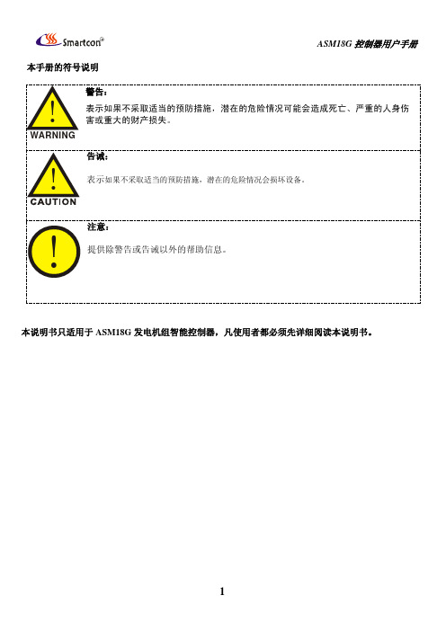
警告: 在安装、操作控制器时,请先阅读整个使用手册,或对该备进行任何维护和调试,必 须熟悉所有设备、安全规范及做好事前预防措,否则可能造成人身伤害或相关设备损 坏。
发动机或其它动力装置必须装配一个超速关机保护装置,以避免原动力装置的失控或损坏而造成人 员伤亡或其它损害。
本手册的符号说明
ASM18G 控制器用户手册
警告:
isis中英文元件名称对照
AD芯片-----TECHWELL TW6805A仿真软件里的AD0809有问题,用0808代替定时/计数器的使用方法:CLK:计数和测频状态时,数字波的输入端。
(counter enable)CE:计数使能端;通过属性设置高还是低有效。
无效暂停计数RST:复位端(RESET),可设上升沿(Low-High)或者下降沿(High-Low)有效。
4种工作方式:通过属性Operating Mode 来选择。
Default : 缺省方式,计数器方式。
Time(secs):100S定时方式,由CE和RST 控制暂停和重新开始。
Time(hms):10小时定时方式,同上。
Frequency: 测频方式,CE和RST有效时,显示CLK端数字波频率Count:计数方式。
+++++++++++++++++++++++++++++++++ ++++++++++++++++++++++++++++常用元件列表:POT-HG 可调电位器7SEG-MPX8-CC-BLUE 8位数码管COMPIM 串口SW- 开关7SEG-BCD 含译码驱动的数显Speaker 扬声器2N5771和2N5772,15V对管300MARES , CAP,BUTTON 按钮开关KEYPAD-PHONE 3*4电话键盘KEYPAD-SMALLCALC 4*4计算器键盘KEYPAD-CALCULATOR 4*6计算器键盘PG160128A 128*128液晶++++++++元件库详细分类1.analog ics 模拟集成器件8个子类:amplifier 放大器comparators 比较器display drivers 显示驱动器filters 滤波器miscellaneous 混杂器件regulators 三端稳压器timers 555定时器voltage references 参考电压2,capacitors CAP电容,23个分类别animated 可显示充放电电荷电容audio grade axial 音响专用电容axial lead polypropene 径向轴引线聚丙烯电容axial lead polystyrene 径向轴引线聚苯乙烯电容ceramic disc 陶瓷圆片电容decoupling disc 解耦圆片电容high temp radial 高温径向电容high temp axial electrolytic高温径向电解电容metallised polyester film 金属聚酯膜电容metallised polypropene 金属聚丙烯电容metallised polypropene film 金属聚丙烯膜电容miniture electrolytic 微型电解电容multilayer metallised polyester film 多层金属聚酯膜电容mylar film 聚酯薄膜电容nickel barrier 镍栅电容non polarised 无极性电容polyester layer 聚酯层电容radial electrolytic 径向电解电容resin dipped 树脂蚀刻电容tantalum bead 钽珠电容variable 可变电容vx a xial electrolytic VX 轴电解电容3,CMOS 4000 series 4000系列数字电路adders 加法器buffers & drivers 缓冲和驱动器comparators 比较器counters 计数器decoders 译码器encoders 编码器flip-flops & latches 触发器和锁存器frequency dividers & tiner 分频和定时器gates & inverters 门电路和反相器memory 存储器misc.logic 混杂逻辑电路mutiplexers 数据选择器multivibrators 多谐振荡器phase-locked loops(PLL) 锁相环registers 寄存器signal switcher 信号开关4,connectors 接头;8个分类:audio 音频接头D-type D型接头DIL 双排插座header blocks 插头miscellaneous 各种接头PCB transfer PCB 传输接头SIL 单盘插座ribbon cable 蛇皮电缆terminal blocks 接线端子台5,data converters 数据转换器:4个分类:A/D converters 模数转换器D/A converters 数模转换器sample & hold 采样保持器temperature sensors 温度传感器6,debugging tools 调试工具数据:3个类别:breakpoint triggers 断点触发器logic probes 逻辑输出探针logic timuli 逻辑状态输入7,diodes 二极管;8个分类:bridge rectifiers 整流桥generic 普通二极管rectifiers 整流二极管schottky 肖特基二极管switching 开关二极管tunnel 隧道二极管varicap 稳压二极管8,inductors 电感:3个类别:generic 普通电感SMT inductors 表面安装技术电感transformers 变压器9,laplace primitives 拉普拉斯模型:7个类别:1st order 一阶模型2nd order 二阶模型controllers 控制器non-linear 非线性模型operators 算子poles/zeros 极点/零点symbols 符号10,memory ICs 存储器芯片:7个分类:dynamic RAM 动态数据存储器EEPROM 电可擦出程序存储器EPROM 可擦出程序存储器I2C memories I2C 总线存储器memory cards 存储卡SPI Memories SPI 总线存储器static RAM 静态数据存储器11,microprocessor ICs 微处理器:13个分类:12,modelling primitivvves 建模源:9个分类:13,operational amplifiers 运算放大器:7个分类:dual 双运放ideal 理想运放macromodel 大量使用的运放octal 8运放quad 4运放single 单运放triple 三运放14,optoelectronics 光电器件:11个分类:7-segment displays 7段显示alphanumeric LCDs 液晶数码显示bargraph displays 条形显示dot matrix displays 点阵显示graphical LCDs 液晶图形显示lamps 灯LCD controllers 液晶控制器LCD controllers 液晶面板显示LEDs 发光二极管optocouplers 光电耦合serial LCDs 串行液晶显示15,resistors 电阻:11个分类:0.6w metal film 0.6w金属膜电阻10 watt wirewound 10w绕线电阻2w metal film 2w 金属膜电阻3 watt wirewound 3w 绕线电阻7 watt wirewound 7w 绕线电阻generix 普通电阻high voltage 高压电阻NTC 负温度系数热敏电阻resistor packs 排阻variable 滑动变阻器varisitors可变电阻参考试验中采用的可变电阻是:POT-HG16,simulator primitives 仿真源:3个类别:flip-flops 触发器gates 门电路sources 电源17,switches and relays 开关和继电器:4个类别:key pads 键盘relays 普通继电器relays(specific) 专用继电器switches 开关18,switching devices 开关器件:4个分类:DIACs 两端交流开关generic 普通开关元件SCRs 可控硅TRIACs 三端双向可控硅19,真空管:20,传感器:2个分类:pressure 压力传感器temperature 温度传感器21,晶体管:8个分类:bipolar 双极型晶体管generic 普通晶体管(错误)IGBT 绝缘栅双极晶体管JFET 结型场效应管MOSFET 金属氧化物场效应管RF power LDMOS 射频功率LDMOS管RF power VDMOS 射频功率VDMOS管unijunction 单结晶体管Electromechanical 电机MOTOR AC 交流电机MOTOR SERVO 伺服电机双相步进电机motor-bistepper(Bipolar Stepper Motor),四相步进电机motor-stepper(unipolar stepper motor)驱动电路,用ULN2003可以,proteus中推荐的L298和L6201(电子元件-步进电机中有L298资料)+++++++++++++++++++++++++++++++++ +++++++++++++++++++++++++++++++++ +++步进电机,可以用MTD2003,UN2916等专用芯片Proteus中图形液晶模块驱动芯片一览表LM3228 LM3229 LM3267 LM3283LM3287 LM4228 LM4265 LM4267LM4283 LM4287 PG12864F PG24064FPG128128A PG160128AAGM1232G EW12A03GL Y HDM32GS12-B HDM32GS12Y-B HDG12864F-1 HDS12864F-3 HDG12864L-4 HDG12864L-6NOKIA7110 TG126410GFSB TG13650FEYAMPIRE128x64 LGM12641BS1R PROTEUS原理图元器件库详细说明Device.lib 单双向可控硅、包括电阻、电容、二极管、三极管和PCB的连接器符号、ACTIVE.LIB 包括虚拟仪器和有源器件、拨动开关、键盘、可调电位器和开关、DIODE.LIB 包括二极管和整流桥、稳压管、变容二极管、大功率二极管、高速二极管、可控硅、DISPLAY.LIB 包括LCD、LED、LED 阵列BIPOLAR.LIB 包括三极管FET.LIB 包括场效应管ASIMMDLS.LIB 包括模拟元器件AS 稳压二极管、全桥、74系列、及其他。
AT90S2313芯片资料,中文

AT90S2313 包含 128 字节的 EEPROM 它是作为一个独立的数据空间而存在的 可以按字 节读写 EEPROM 的寿命至少为 100000 次 擦除 EEPROM 的访问由地址寄存器 数据 寄存器和控制寄存器决定
SRAM
图 8 表明了 AT90S2313 的数据组织方式 图8
寄存器文件
R0 R1 R2 … R29 R30 R31 I/O 寄存器
X Y Z寄存器
寄存器 R26~R31 除了用作通用寄存器外 还可以作为数据间接寻址用的地址指针
图 7 X Y Z 寄存器
15
0
X 寄存器
7
07
0
R27 $1B
R26 $1A
Y 寄存器
15
0
7
07
0
R29 $1D
R28 $1C
Z 寄存器
15 7
R31 $1F
0
07
0
R30 $1E
ALU
AVR ALU 与 32 个通用工作寄存器直接相连 ALU 操作分为 3 类 算术 逻辑和位操作
AT90S2313
AT90S2313
特点
1. AVR RISC 结构 2. AVR 高性能 低功耗 RISC 结构
118 条指令 大多数为单指令周期 32 个 8 位通用 工作 寄存器 工作在 10MHz 时具有 10MIPS 的性能 3. 数据和非易失性程序内存 2K 字节的在线可编程 FLASH 擦除次数 1000 次 128 字节 SRAM 128 字节在线可编程 EEPROM 寿命 100000 次 程序加密位 4. 外围 Peripheral 特点 一个可预分频 Prescale 的 8 位定时器/计数器 一个可预分频 具有比较 捕捉和 8- 9- 10 位 PWM 功能的 16 位定时器/计数器 片内模拟比较器 可编程的看门狗定时器 由片内振荡器生成 用于下载程序的 SPI 口 全双工 UART 5. 特别的 MCU 特点 低功耗空闲和掉电模式 内外部中断源 6. 规范 Specification 低功耗 高速 CMOS 工艺 全静态工作 7. 4MHz 3V 25 条件下的功耗 工作模式 2.8mA 空闲模式 0.8mA 掉电模式 <1 A 8. I/O 和封装 15 个可编程的 I/O 脚 20 脚 PDIP 和 SOIC 封装 9. 工作电压 2.7V-6.0V AT90S2313-4 4.0V-6.0V AT90S2313-10 10. 速度 0-4MHz AT90S2313-4 0-10MHz AT90S2313-10
MICREL MIC1815 Microprocessor Reset Circuit 数据手册

Power Dissipation (TA = +70°C) . . . . . . . . . . . . . . . . 320mW
Stresses above those listed under ABSOLUTE MAXIMUM RATINGS may cause permanent device failure. Functionality at or above these limits is not implied. Exposure to absolute maximum ratings for extended periods may affect device reliability. Operating ranges define those limits between which the functionality of the device is guaranteed.
Pin Configuration
Top View
RESET 1
MIC1815
VCC 2
3 GND
Typical Applications
· Portable Equipment · Intelligent Instruments · Critical Microprocessor Power Monitoring · Printers/Computers · Controllers
8++
8JDH
8JDH
asserted for a period of 150ms after VCC has risen
J
J
above the reset threshold voltage. The reset function
TM1803系列产品的优势介绍
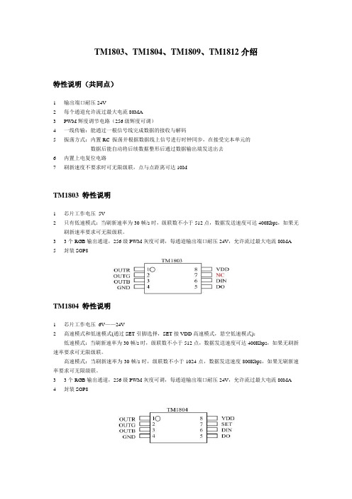
TM1803、TM1804、TM1809、TM1812介绍特性说明(共同点)1 输出端口耐压24V2 每个通道允许流过最大电流80MA3 PWM辉度调节电路(256级辉度可调)4 一线传输:能通过一根信号线完成数据的接收与解码5 振荡方式:内置RC 振荡并根据数据线上信号进行时钟同步,在接受完本单元的数据后能自动将后续数据整形后通过数据输出端发送出去6 内置上电复位电路7 刷新速度不要求时可无限级联,点与点距离可达10MTM1803 特性说明1芯片工作电压5V2只有低速模式:当刷新速率为30帧/s时,级联数不小于512点,数据发送速度可达400Kbps,如果无刷新速率要求可无限级联。
33个RGB输出通道,256级PWM灰度可调,每通道输出端口耐压24V,允许流过最大电流80MA5 封装SOP8TM1804 特性说明1芯片工作电压6V——24V2高速模式和低速模式(通过SET引脚选择,SET接VDD高速模式,悬空低速模式):低速模式:当刷新速率为30帧/s时,级联数不小于512点,数据发送速度可达400Kbps,如果无刷新速率要求可无限级联。
高速模式:当刷新速率为30帧/s时,级联数不小于1024点,数据发送速度800Kbps,如果无刷新速率要求可无限级联。
33个RGB输出通道,256级PWM灰度可调,每通道输出端口耐压24V,允许流过最大电流80MA4 封装SOP8TM1809 特性说明1芯片工作电压6V——24V2高速模式和低速模式(通过SET引脚选择,SET接VDD高速模式,悬空低速模式):低速模式:当刷新速率为30帧/s时,级联数不小于512点,数据发送速度可达400Kbps,如果无刷新速率要求可无限级联。
高速模式:当刷新速率为30帧/s时,级联数不小于1024点,数据发送速度800Kbps,如果无刷新速率要求可无限级联。
39个RGB输出通道,256级PWM灰度可调,每通道输出端口耐压24V,允许流过最大电流80MA4 封装SOP14TM1812 特性说明1芯片工作电压6V——24V2只有高速模式:当刷新速率为30帧/s时,级联数不小于1024点,数据发送速度800Kbps,如果无刷新速率要求可无限级联。
ST AN1813 数据手册
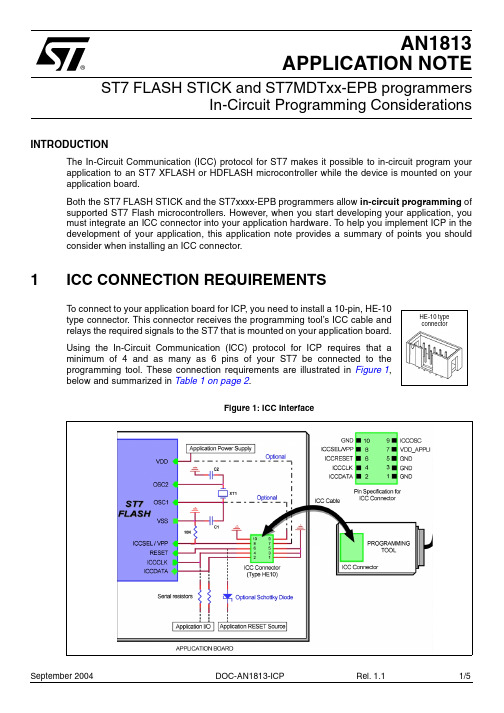
®September 2004 DOC-AN1813-ICP Rel. 1.1 1/5AN1813APPLICATION NOTEST7 FLASH STICK and ST7MDTxx-EPB programmersIn-Circuit Programming ConsiderationsINTRODUCTIONThe In-Circuit Communication (ICC) protocol for ST7 makes it possible to in-circuit program your application to an ST7 XFLASH or HDFLASH microcontroller while the device is mounted on your application board.Both the ST7 FLASH STICK and the ST7xxxx-EPB programmers allow in-circuit programming of supported ST7 Flash microcontrollers. However, when you start developing your application, you must integrate an ICC connector into your application hardware. To help you implement ICP in the development of your application, this application note provides a summary of points you should consider when installing an ICC connector.1ICC CONNECTION REQUIREMENTSTo connect to your application board for ICP , you need to install a 10-pin, HE-10type connector. This connector receives the programming tool’s ICC cable andrelays the required signals to the ST7 that is mounted on your application board.Using the In-Circuit Communication (ICC) protocol for ICP requires that aminimum of 4 and as many as 6 pins of your ST7 be connected to theprogramming tool. These connection requirements are illustrated in Figure 1,below and summarized in Table 1 on page 2.Figure 1: ICC Interface HE-10 typeconnectorST7 Visual Debug Application Note Note:When using the ST7MDTS1-EPB, VDD_APPLI is not connected to the ST7. When setting up your application for in-circuit programming, refer to the ICP Interface diagram in the In-CircuitProgramming section of the ST7SCR Datasheet, instead of the diagram provided in Figure 1.ST7 pin Connects toICCDATA ICC input serial data pin ICCDATAICCCLK ICC output serial clock pin ICCCLKRESET Device reset ICCRESETICCSEL/VPP Programming voltage ICCSEL/VPPOSC1 or OSCIN * #Main clock input for external ICCOSCVDD *Device power supply VDD_APPLIVSS Device power supply (ground)GND* Optional connection for the STICK, see text.#Optional connection for ST7MDTxx-EPB, see text.Table 1: ICC connection requirementsIsolation of ICCDATA and ICCCLK pinsAs soon as an ICP tool is plugged into the application board the ICCDATA and ICCCLK pins must not be used by other application devices, even if an ICC session is not in progress. If the application uses these pins as inputs, isolation such as a serial resistor must be implemented to prevent other application devices from forcing a signal on either of these pins. The application board must not drive current in excess of 1mA.If the ICCDATA and ICCCLK pins are only used as outputs by the application, no signal isolation is necessary.For ST7 without an ICCSEL pin, during normal operation the ICCCLK pin must be pulled-up internally or externally (10KΩ pull-up required in noisy environments). This is to avoid entering ICC mode unintentionally during a reset.Isolation of the RESET pinDuring an ICC session, you must ensure that the programming tool controls the ST7’s RESET pin so that no external reset is generated by the application. This can lead to a conflict if the application reset circuitry signal exceeds 5mA (push-pull output or pull-up resistor <1k). To avoid such conflicts,a Shottky diode can be used to isolate the application reset circuit.ICCSEL/VPP pinThe application pull-down resistor must not be lower than 10kΩ.ICCOSC pin * #The ICCOSC pin of the ICC connector must be connected to the ST7’s OSC1 or OSCIN pin if the clock is not provided by the application, or if the application clock source is not programmed in the option byte. This connection allows you to start your ICP session using the ICP OPT Disable programming mode. In this mode, the programming tool provides a clock source to initiate communication with the ST7. The STICK provides a clock source at a frequency of 8MHz; the ST7MDTxx-EPB clock frequency is 16MHz.2/5 DOC-AN1813-ICPApplication Note ST7 Visual Debug For ST7 devices with multi-oscillator capability, when the ICCOSC pin is connected, the OSC2 pin should be grounded.If your application provides a clock signal and you are certain that it is programmed in the ST7’s option byte, you can start your ICP session using the ICP OPT Enable programming mode. In this mode, your application clock source provides the clock signal for initiating communication with your ST7 and ICCOSC is not connected to your ST7.Caution:For all versions of the following EPBs, the ICCOSC pin must not be connect to the device’s OSCIN pin:• ST7MDTU2-EPB•ST7MDTU3-EPB• ST7MDTU5-EPBNote:The ST7MDTxx-EPB programmer provides a clock signal when using both the ICP OPT Disable and ICP OPT Enable programming modes. If you start your ICP session using ICP OPT Enable, the clock signal provided by the programmer may conflict with the application clock and can cause a communication failure with your ST7. To avoid this we recommend installing a jumper on theconnection between ICCOSC and the ST7. This jumper is removed when starting in the ICP OPT Enable programming mode. If the user requires a clock signal from the programmer to start in the ICP OPT Disable mode, the jumper is left in place.VDD_APPLI pin *This pin is used by the programming tool’s power supply follower, which adapts the voltage of the tool’s signals to your application’s V DD.Whether you connect the VDD_APPLI pin depends on your programming tool. It must be connected when using any ST7MDTxx-EPB programmer with ICP capability, except the ST7MDTS1-EPB. It can also be connected when programming with the ST7-STICK depending on the voltage used by your application.For the STICK, if the application board VDD is equal to 5v or 3.3v, VDD_APPLI is not connected.However, the W1 jumper must be set to the appropriate position (5v or 3.3v). For all other VDD values supported by your ST7 (refer to ST7xxxx Datasheet), this pin must be connected and the W1 jumper set to the VDD position.ICC cableYour programming tool includes an ICC cable for connecting to the HE-10 type connector on your application board. The provided cable is 30cm long, however you can use a cable up to 2 meters long. Typical characteristics for provided ICC cable are provided in Table2, below.Table 2: Typical ICC cable characteristicsDOC-AN1813-ICP3/5ST7 Visual Debug Application Note 2TROUBLE SHOOTING“Communication failure with the ST7”Check that:q The ICC cable is properly connected.q You have selected the right ST7 microcontroller.q Your hardware set up meets the ICC requirements specified in this documentq You have selected the right programming mode:ICP OPT Enable: you are certain that your application clock matches the CLOCK SOURCEand OSCTYPE options that are already programmed in ST7 Flash microcontroller option byte.If you don’t know these values, select ICP OPT Disable.ICP OPT Disable:ensure that external clock source from the ICC connector (ICCOSC, pin 9)is connected to the OSC1 or OSCIN pin of the ST7Flash microcontroller in your application “Supply voltage problems” (STICK)When you have supply voltage problems, i.e. the green LED will not come on.Check that:q The AC/DC power supply adaptor is firmly connected.q The W1 jumper is set to the correct position for your application:VDD— when using the voltage supply follower for voltages ranging between 2.4 and 5 V.Ensure that the ST7’s VDD pin is connected to the VDD_APPLI pin on the ICC connector.3.3V or 5V— if your application uses either of these voltages and you are not using thevoltage follower feature.4/5 DOC-AN1813-ICPApplication Note ST7 Visual Debug "THE PRESENT NOTE, WHICH IS FOR GUIDANCE ONLY, AIMS TO PROVIDE CUSTOMERS WITH INFORMATION REGARDING THEIR PRODUCTS IN ORDER FOR THEM TO SAVE TIME.AS A RESULT, STMICROELECTRONICS SHALL NOT BE HELD LIABLE FOR ANY DIRECT, INDIRECT OR CONSEQUENTIAL DAMAG ES WITH RESPECT TO ANY CLAIMS ARISING FROM THE CONTENT OF SUCH A NOTE AND/OR THE USE MADE BY CUSTOMERS OF THE INFORMATION CONTAINED HEREIN IN CONNEXION WITH THEIR PRODUCTS."Information furnished is believed to be accurate and reliable. However, STMicroelectronics assumes no responsibility for the consequences of use of such information nor for any infringement of patents or other rights of third parties which may result from its use. No license is granted by implication or otherwise under any patent or patent rights of STMicroelectronics. Specifications mentioned in this publication are subject to change without notice. This publication supersedes and replaces all information previously supplied. STMicroelectronics products are not authorized for use as critical components in life support devices or systems without the express written approval ofSTMicroelectronics.The ST logo is a registered trademark of STMicroelectronics2004 STMicroelectronics - All Rights Reserved.Purchase of I2C Components by STMicroelectronics conveys a license under the Philips I2C Patent. Rights to use these components in an I2C system is granted provided that the system conforms to the I2C Standard Specification as defined by Philips.STMicroelectronics Group of CompaniesAustralia - Brazil - Canada - China - Finland - France - Germany - Hong Kong - India - Israel - Italy - JapanMalaysia - Malta - Morocco - Singapore - Spain - Sweden - Switzerland - United Kingdom - U.S.A.DOC-AN1813-ICP5/5。
3B18中文资料
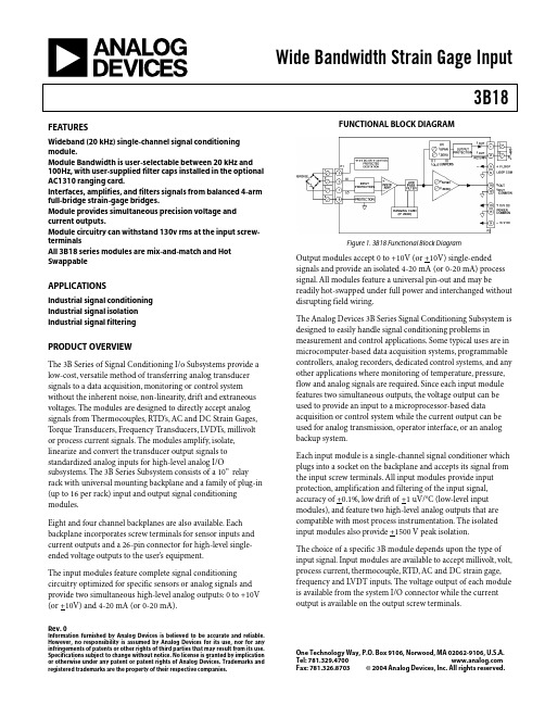
Wide Bandwidth Strain Gage Input3B18Rev. 0Information furnished by Analog Devices is believed to be accurate and reliable. However, no responsibility is assumed by Analog Devices for its use, nor for any infringements of patents or other rights of third parties that may result from its use. Specifications subject to change without notice. No license is granted by implication or otherwise under any patent or patent rights of Analog Devices. Trademarks and registered trademarks are the property of their respective companies.One Technology Way, P.O. Box 9106, Norwood, MA 02062-9106, U.S.A.Tel: 781.329.4700 Fax: 781.326.8703© 2004 Analog Devices, Inc. All rights reserved.FEATURESWideband (20 kHz) single-channel signal conditioning module.Module Bandwidth is user-selectable between 20 kHz and 100Hz, with user-supplied filter caps installed in the optional AC1310 ranging card.Interfaces, amplifies, and filters signals from balanced 4-arm full-bridge strain-gage bridges.Module provides simultaneous precision voltage and current outputs.Module circuitry can withstand 130v rms at the input screw-terminalsAll 3B18 series modules are mix-and-match and Hot SwappableAPPLICATIONSIndustrial signal conditioning Industrial signal isolation Industrial signal filteringPRODUCT OVERVIEWThe 3B Series of Signal Conditioning I/o Subsystems provide a low-cost, versatile method of transferring analog transducer signals to a data acquisition, monitoring or control system without the inherent noise, non-linearity, drift and extraneous voltages. The modules are designed to directly accept analog signals from Thermocouples, RTD’s, AC and DC Strain Gages, Torque Transducers, Frequency Transducers, LVDTs, millivolt or process current signals. The modules amplify, isolate, linearize and convert the transducer output signals to standardized analog inputs for high-level analog I/Osubsystems. The 3B Series Subsystem consists of a 10” relay rack with universal mounting backplane and a family of plug-in (up to 16 per rack) input and output signal conditioning modules.Eight and four channel backplanes are also available. Each backplane incorporates screw terminals for sensor inputs and current outputs and a 26-pin connector for high-level single-ended voltage outputs to the user’s equipment.The input modules feature complete signal conditioning circuitry optimized for specific sensors or analog signals and provide two simultaneous high-level analog outputs: 0 to +10V (or +10V) and 4-20 mA (or 0-20 mA).FUNCTIONAL BLOCK DIAGRAMFigure 1. 3B18 Functional Block DiagramOutput modules accept 0 to +10V (or +10V) single-ended signals and provide an isolated 4-20 mA (or 0-20 mA) process signal. All modules feature a universal pin-out and may bereadily hot-swapped under full power and interchanged without disrupting field wiring.The Analog Devices 3B Series Signal Conditioning Subsystem is designed to easily handle signal conditioning problems inmeasurement and control applications. Some typical uses are in microcomputer-based data acquisition systems, programmable controllers, analog recorders, dedicated control systems, and any other applications where monitoring of temperature, pressure, flow and analog signals are required. Since each input module features two simultaneous outputs, the voltage output can be used to provide an input to a microprocessor-based data acquisition or control system while the current output can be used for analog transmission, operator interface, or an analog backup system.Each input module is a single-channel signal conditioner which plugs into a socket on the backplane and accepts its signal from the input screw terminals. All input modules provide input protection, amplification and filtering of the input signal, accuracy of +0.1%, low drift of +1 uV/o C (low-level input modules), and feature two high-level analog outputs that are compatible with most process instrumentation. The isolated input modules also provide +1500 V peak isolation.The choice of a specific 3B module depends upon the type of input signal. Input modules are available to accept millivolt, volt, process current, thermocouple, RTD, AC and DC strain gage, frequency and LVDT inputs. The voltage output of each module is available from the system I/O connector while the current output is available on the output screw terminals.3B18Rev. 0 | Page 2 of 8GENERAL DESCRIPTIONThe 3B18 is a wideband (20kHz) single-channel signal conditioning module which interfaces, amplifies, and filters signals from balanced 4-arm full-bridge strain-gage bridges with a resistance from 100Ω to 10 k Ω, providing simultaneous precision voltage and current outputs. The module provides two user-selectable (via front-panel switches) bridge excitation voltages: +10 V for bridges with a load impedance down to 300W or +3.33V for 120W bridges or others below 300W . Module bandwidth is also user-selectable between 20 kHz and 100 Hz, with user-supplied filter capacitors installed in theoptional AC1310 ranging card. The 3B18 protects the computer side from damage due to field-side over-voltage faults up to 130V rms. In addition, the current output withstands 130V rms without damage and interfaces user equipment through screw terminals located on the 3B Series backplane. The 3B18 is a plug-in, mix-and-match, hot-swappable module which is easily field calibrated via front-panel zero and span adjustments for both voltage and current outputs.3B Series Custom-Ranging Program – Externally-programmable Model 3B18-00, enables the user to configure a special input range by using the optional plug-on AC1310ranging card, which houses user-supplied resistors to determine zero and span. To facilitate selecting resistors, a Windowsprogram, 3B-CUSTOM, calculates resistor values based on the user-desired input/output ranges.A chopper-stabilized low-drift (+1uV/o C) input amplifierassures long-term stability. For user convenience, the zero and span can be factory configured to meet custom range needs (Model 3B18-CUSTOM) or can be externally programmed (Model 3B18-00) via user supplied resistors inserted in the optional AC1310 plug-on ranging card...Figure 23B18Rev. 0 | Page 3 of 83B18 Models AvailableModel Input Bridge InputRange Excitation 1 Sensitivity Output Ranges3B18-00 Full Bridge Externally Programmable 3 +10.0 V or +3.33 V Externally Programmable 3 -10 V to +10 V & 0 mA to 20 mA 3B18-01 Full Bridge -30 mV to +30 mV +10.0 V or +3.33 V 3 mV/V @ 10 Vexc -10 V to +10 V & 0 mA to 20 mA 3B18-02 Full Bridge -10 mV to +10 mV+10.0 V or +3.33 V 3 mV/V @ 3.33 Vexc-10 V to +10 V & 0 mA to 20 mA3B18-CustomFull Bridge*+10.0 V or +3.33 V**1Output current range may be user programmed to 4 mA to 20 mA using jumper supplied. 2Requires AC1310 ranging card.* Custom Input/Output ranges are available. Refer to configuration guide.3B18 Specifications(typical @ +25°C and ±15 V dc, and +24 V dc Power)Description Model 3B18Input RangeStandard Range ±30 mV (3 mV/V sensitivity @ V exc = +10V) ±10 mV (3 mV/V sensitivity @ V exc = +3.33 V) Custom Ranges±5 mV to ±500 Output RangeVoltage (R L > 2 K Ω) -10 V to +10 VCurrent (R L = 0 to 850Ω)1 4 mA to 20 mA or 0 mA to 20 mA Maximum Current Output Span0 mA to 31 mAAccuracy 2Initial @ +25°C±0.1% SpanNonlinearity 2 ±0.01%Span Stability vs. TemperatureVoltage Output Zero ±3 µV/°C (RTI) Span ±25 ppm of Reading/°CCurrent Output 3 Zero ±25 ppm of Span/°C Span±25 ppm of Reading/°CBridge ExcitationVoltage user-selectable +10 V or +3.33 V Voltage, tolerance ±2% Voltage vs. Temperature±0.0015%/°CBridge Resistance RangeV exc = +10.0 V300 Ωto 1 k Ω3B18Rev. 0 | Page 4 of 8V exc = +3.33 V100 Ωto 10 k Ω Zero and Span Adjustment Range 4 ±5% of Span Input Bias Current +25 nA Input Resistance 100 M Ω Bandwidth, -3 dB20 kHz Output Rise Time, 10% to 90% Span24µsCommon-Mode Voltage (CMV)Input-to-Output, Continuous ±10 V peak, maximum TransientANSI/IEEE C37.90.1- 1989Common Mode Rejection (CMR)1 kSource Imbalance, 50/60 Hz100 dBInput Protection, Signal and Excitation VoltageContinuous130 V rms maximumTransient ANSI/IEEE C37.90.1-1989 Voltage Output Protection Continuous Short to Ground Current Output Protection130 V rms, continuousPower Supply Voltages 5±15 V dc Supplies Rated Operation ±(13.5 V dc to 16.5 V dc) Current +50 mA, -15 mA Sensitivity±0.01% span/V+24 V dc Loop Supply Rated Operation +12 V dc to +30 V dc Current +27 mA @ l out = 20 mA Sensitivity±0.0002% span/VMechanical Dimensions3.15" x 3.395" x 0.775"(80.0 mm x 86.2 mm x 19.7 mm) EnvironmentalTemperature Range Rated Performance -25°C to +85°C Storage-55°C to +85°CRelative Humidity, 24 hours 0 to 95% @ +60°C non-condensing RFI Susceptibility±0.5% Span error @ 400 MHz, 5 Watt, 3 ft1 For a 0 mA to 20 mA range, a typical minimum output current is 10 µA. 2Includes the combined effects of repeatability, hysteresis, and nonlinearity. 3With respect to the voltage output. 4A wide range of custom zero suppression and span is available with the 3B18-00 model, using the AC1310 ranging card. 5+24 V dc loop power is required for driving the current output at loads up to 850Ω. If a current output load of 400Ω or less is applied, +15 V dc is sufficient for loop power. If only voltage output is used, loop power is not required.3B18Rev. 0 | Page 5 of 8PIN CONFIGURATIONS AND FUNCTIONAL DESCRIPTIONSFigure 3 3B18 Input Field ConnectionsTable 1. Pin Function Descriptions—Pin No.Description 1 +EXC 2 HI 3 LO 4 -EXCFigure 4 . Model 3B Series Module, with pin-out assignments.ESD CAUTIONESD (electrostatic discharge) sensitive device. Electrostatic charges as high as 4000 V readily accumulate on the human body and test equipment and can discharge without detection. Although this product features proprietary ESD protection circuitry, permanent damage may occur on devices subjected to high energy electrostatic discharges.Therefore, proper ESD precautions are recommended to avoid performance degradation or loss of functionality.3B18Rev. 0 | Page 6 of 8OUTLINE DIMENSIONSFigure 5. Outline Dimensions3B18 NOTESRev. 0 | Page 7 of 83B18Rev. 0 | Page 8 of 8NOTES© 2004 Analog Devices, Inc. All rights reserved. Trademarks and registered trademarks are the property of their respective companies. D05091-0-9/04(0)。
18-18-2(XM15)不锈钢不锈钢带材
18-18-2(XM15)不锈钢不锈钢带材
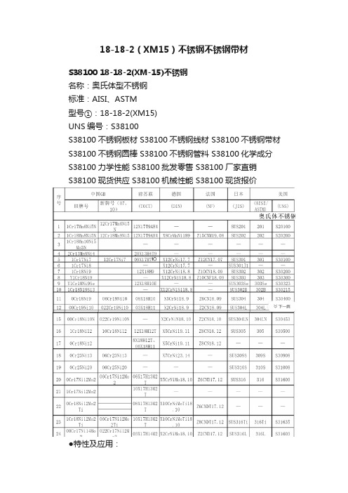
S38100 18-18-2(XM-15)不锈钢
名称:奥氏体型不锈钢
标准:AISI、ASTM
型号①:18-18-2(XM15)
UNS编号:S38100
S38100不锈钢板材 S38100不锈钢线材 S38100不锈钢带材S38100不锈钢圆棒 S38100不锈钢管料 S38100化学成分S38100力学性能 S38100批发零售 S38100厂家直销
S38100现货供应 S38100机械性能 S38100现货报价
●特性及应用:
18-18-2(XM15)不锈钢,美国非标准奥氏体不锈钢。
●化xue成分②:
碳 C:≤0.08
锰 Mn:≤2.00
硅 Si:1.5~2.5
铬 Cr:17.0~19.0
镍 Ni:17.58~18.5
磷 P:≤0.03
硫 S:≤0.03
氮 N:0.08~0.18
注:① 本行中XM牌号,是该表所列合金的ASTM牌号。
圆括弧内的型号,是已作废的AISI牌号;②单一数值除非另有说明者外均为最高值;③最高值为1.00%;④公称成分;没有可用的成分范围;⑤最高值为0.50%;⑥最高值为0.75%;⑦最高值为0.80%。
日本传世家徽MCUSTAMC-183D大马士革钢折刀

日本传世家徽MCUSTAMC-183D大马士革钢折刀
日本传世家徽MCUSTA MC-183D 大马士革钢折刀
基本介绍
本文章来源:主题名品网。
MCUSTA 日本传世家徽MC-183D Ieyasu 家康耐力木柄大马士革钢折刀
Ieyasu Tokugawa 德川家康(1543-1616),是德川幕府的创始人和第一代征夷大将军,日本战国三英杰之一,杰出的政治家和军事家,在1600年统帅了著名的关原之战(Sekigahara)。
这款MC-183D Ieyasu 德川家康大马士革便是为了怀念这位在日本发展史中做出巨大贡献的战国将领。
刀身采用VG-10钢为核心的大马士革钢锻造,经过平磨的刀身拥有极佳的锋利度,流畅的切割感受将给使用者一种别样的体验,锋利的刀尖和狭长假刃让刀具的穿刺力十足。
刀身采用烤蓝处理的双侧推刀柱进行开刀,再配上独特的涂油特氟隆垫圈系统保证了刀具拥有流畅的开合动作。
衬垫锁结构保障了刀具的安全性,经过抛光的不锈钢内衬外贴附有一层棕/黑色耐力木(Staminawood)材质贴片,表面雕刻的凹凸纹路让使用者拥有更好的把握手感。
柄身中部一侧刻有BUSHIDO和德川字样,并在两侧刻有德川家族纹章。
规格。
MC13136资料
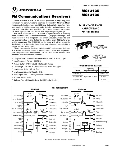
MC13135
1st LO 1st LO Base 1 1st LO Emitter 1st LO Out VCC1 2nd LO Emitter 2nd LO Base 2nd Mixer Out VEE Limiter In
2 3 4 5 6 7
PIN CONNECTIONS
MC13136
1st LO Varicap
元器件交易网
Order this document by MC13135/D
FM Communications Receivers
The MC13135/MC13136 are the second generation of single chip, dual conversion FM communications receivers developed by Motorola. Major improvements in signal handling, RSSI and first oscillator operation have been made. In addition, recovered audio distortion and audio drive have improved. Using Motorola’s MOSAIC™ 1.5 process, these receivers offer low noise, high gain and stability over a wide operating voltage range. Both the MC13135 and MC13136 include a Colpitts oscillator, VCO tuning diode, low noise first and second mixer and LO, high gain limiting IF, and RSSI. The MC13135 is designed for use with an LC quadrature detector and has an uncommitted op amp that can be used either for an RSSI buffer or as a data comparator. The MC13136 can be used with either a ceramic discriminator or an LC quad coil and the op amp is internally connected for a voltage buffered RSSI output. These devices can be used as stand–alone VHF receivers or as the lower IF of a triple conversion system. Applications include cordless telephones, short range data links, walkie–talkies, low cost land mobile, amateur radio receivers, baby monitors and scanners.
tm1812

一、 概述TM1812是12通道LED(发光二极管显示器)驱动控制专用电路,内部集成有MCU 数字接口、数据锁存器、LED 高压驱动等电路。
通过外围 MCU控制实现该芯片的单独辉度、级联控制实现户外大屏、护栏管、幻彩灯条的彩色点阵发光控制。
本产品性能优良,质量可靠。
采用SOP16的封装形式。
二、 特性说明z采用高压功率CMOS工艺z输出端口耐压24Vz芯片工作电压支持5V~24Vz内置稳压电路z辉度调节电路(256级辉度可调)z单线串行级联接口,通过一根信号线完成数据的接收与解码z振荡方式:内置双RC 振荡并根据数据线上信号进行时钟同步z内置上电复位电路z PWM控制端能够实现256级调节,扫描频率不低于400hz/sz当刷新速率为30帧/s时,级联灯个数不小于1080点z数据发送速度800Kbpsz封装形式:SOP16三、管脚定义:VDD DOUT 4OUTR 4OUTG 4OUTB 3OUTR 3OUTG 3OUTBDIN1OUTR 1OUTG 1OUTB 2OUTR 2OUTG 2OUTB GND四、管脚功能定义:管脚号 符号 管脚名称 说明16 DIN 数据输入 显示数据输入2 DOUT 数据输出 显示数据级联输出15 1OUTR LED驱动输出 第1路 Red PWM控制输出14 1OUTG LED驱动输出 第1路 Green PWM控制输出13 1OUTB LED驱动输出 第1路 Blue PWM控制输出12 2OUTR LED驱动输出 第2路 Red PWM控制输出11 2OUTG LED驱动输出 第2路 Green PWM控制输出10 2OUTB LED驱动输出 第2路 Blue PWM控制输出6 3OUTR LED驱动输出 第3路 Red PWM控制输出7 3OUTG LED驱动输出 第3路 Green PWM控制输出8 3OUTB LED驱动输出 第3路 Blue PWM控制输出3 4OUTR LED驱动输出 第4路 Red PWM控制输出4 4OUTG LED驱动输出 第4路 Green PWM控制输出5 4OUTB LED驱动输出 第4路 Blue PWM控制输出1 VDD 逻辑电源 6V±10%9 GND 逻辑地 接系统地五、 电气参数:极限参数(Ta = 25℃, Vss = 0 V)参数 符号 范围 单位 逻辑电源电压 VDD +6.0 ~+7.0 V输出端口耐压 VOUTx 24 V逻辑输入电压 VI1 -0.5 ~ VDD + 0.5 VLED驱动输出电流 IO1 80 mA 功率损耗 PD 400 mW工作温度 Topt -40 ~ +80 ℃储存温度 Tstg -65 ~+150 ℃正常工作范围(Ta = -20 ~ +70℃,Vss = 0 V)参数 符号 最小 典型 最大 单位 测试条件逻辑电源电压 VDD 6 V - 高电平输入电压 VIH 0.7 VDD - VDD V - 低电平输入电压 VIL 0 - 0.3 VDD V -电气特性(Ta=-20~+70℃,VDD=4.5~5.5V,Vss=0V)参数 符号 最小 典型最大 单位 测试条件低电平输出电流 IOL1 80 140 - mA OUTR/OUTG/OUTB Vo=0.3V低电平输出电流 Idout 10 - - mA VO = 0.4V,DOUT 输入电流 II - - ±1 μA VI = VDD / VSS 高电平输入电压 VIH 0.7 VDD- V DIN低电平输入电压 VIL - - 0.3 VDD V DIN 滞后电压 VH - 0.35- V DIN 动态电流损耗 IDDdyn - - 1 mA 无负载,显示关 消耗功率 PD 250 mW (Ta=25°C) 热阻值Rth(j-a) 79.2 190 °C/W开关特性(Ta = -20 ~ +70℃,VDD = 4.5 ~ 5.5 V)参数 符号 最小典型最大单位测试条件Fosc1 - 400 - KHz / 振荡频率Fosc2 - 800 - KHz /tPLZ - - 300 ns DIN → DOUT传输延迟时间tPZL - - 100 ns CL = 15pF, RL = 10K Ω 下降时间 TTHZ - - 120 μs CL = 300pF, OUTR/OUTG/OUTB 数据传输率 Fmax 400 - - Kbps占空比50%输入电容 CI - - 15 pF -六、功能描叙:芯片采用单线通讯方式,采用归零码的方式发送信号。
DS1813 EconoReset 电源故障重启模块说明书

DS1813R-15+DS1813R-5+DS1813-10+.DS1813R-10+1 of 5070303FEATURES§ Automatically restarts a microprocessor after power failure§ Monitors pushbutton for external override § Maintains reset for typically 150 ms after V CCreturns to an in-tolerance condition § Reduces need for discrete components§ Precision temperature-compensated voltage reference and voltage sensor§ Low-cost TO-92 or space saving surface-mount SOT-23 packages available§ Efficient open-drain output with internal 5.5 k W pull-up resistor§ Operating temperature -40°C to +85°CPIN ASSIGNMENTPIN DESCRIPTION TO-921 RST Active Low Reset Output2 V CC Power Supply3 GND GroundSOT-231 RST Active Low Reset Output2 V CC Power Supply3 GND GroundDESCRIPTIONThe DS1813 EconoReset uses a precision temperature reference and comparator circuit to monitor the status of the power supply (V CC ). When an out-of-tolerance condition is detected, an internal power-fail signal is generated which forces reset to the active state. When V CC returns to an in-tolerance condition,the reset signal is kept in the active state for approximately 150 ms to allow the power supply and processor to stabilize.The DS1813 also monitors a pushbutton on the reset output. If the reset line is pulled low, a reset is generated upon release and will be held in reset output low for typically 150 ms.DS18135V EconoReset with Pushbutton12TOP VIEW SOT-23 PACKAGESee Mech.Drawings SectionOn WebsiteBOTTOM VIEW TO-92 PACKAGESee Mech.Drawings Section On WebsiteDS1813 OPERATION - POWER MONITORThe DS1813 provides the functions of detecting out-of-tolerance power supply conditions and warning a processor-based system of impending power failure. When V CC is detected as out-of-tolerance, the RST signal is asserted. On power-up, RST is kept active for approximately 150ms after the power supply has reached the selected tolerance. This allows the power supply and microprocessor to stabilize before RST is released.OPERATION - PUSHBUTTON RESETThe DS1813 provides for a pushbutton switch for manual reset control. When the DS1813 is not in a reset cycle, a pushbutton reset can be generated by pulling the RST pin low for at least 1µs. When the pushbutton is held low, the RESET is forced active low and will remain active low for about 150ms after the pushbutton is released. See Figure 2 for an application example and Figure 3 for the timing diagram. BLOCK DIAGRAM (OPEN-DRAIN OUTPUT) Figure 1APPLICATION EXAMPLE Figure 2DS1813 TIMING DIAGRAM: PUSHBUTTON RESET Figure 3TIMING DIAGRAM: POWER-UP Figure 4TIMING DIAGRAM: POWER-DOWN Figure 5DS1813ABSOLUTE MAXIMUM RATINGS*Voltage on V CC Pin Relative to Ground -0.5V to +7.0VVoltage on RST Relative to Ground -0.5V to +5V CC +0.5V Operating Temperature -40°C to +85°C Storage Temperature -55°C to +125°C Soldering Temperature260°C for 10 seconds* This is a stress rating only and functional operation of the device at these or any other conditions above those indicated in the operation sections of this specification is not implied. Exposure to absolute maximum rating conditions for extended periods of time may affect reliability.RECOMMENDED DC OPERATING CONDITIONS (-40°C to +85°C)PARAMETER SYMBOL MIN TYPMAX UNITS NOTES Supply VoltageV CC0.05.5V1DC ELECTRICAL CHARACTERISTICS (-40°C to +85°C; V CC =1.2V to 5.5V)PARAMETERSYMBOLMIN TYPMAXUNITS NOTES **********************I OL +10mA 2, 3Voltage Input Low V IL 0.4V 1Voltage Input High V IH 0.7*V CCV 1Operating Current V CC < 5.5I CC 3040m A 4V CC Trip Point (DS1813-5)V CCTP 4.50 4.62 4.75V 1V CC Trip Point (DS1813-10)V CCTP 4.25 4.35 4.49V 1V CC Trip Point (DS1813-15)V CCTP 4.00 4.13 4.24V 1Internal Pull-Up Resistor R P 3.50 5.57.5k6Output CapacitanceC OUT10pFDS1813NOTES:1. All voltages are referenced to ground.2. Measured with V CC ³ 2.7 volts.3. A 1k W external resistor may be required in some applications for proper operation of the microprocessor reset control circuit.4. Measured with RST output open.5. t R = 5 m s.6. V OH and I OH are a function of the value of R P and the associated output load conditions.7. This value is for reference in defining values for T RPD and should not be considered a requirement forproper operation or use of the device.PART MARKING CODES“A”, “B”, &“C” represent the device type.810 . . . . DS1810811 . . . . DS1811812 . . . . DS1812813 . . . . DS1813815 . . . . DS1815816 . . . . DS1816817 . . . . DS1817818 . . . . DS1818“D” represents the device tolerance.A . . . . . . 5%B . . . . . . 10%C . . . . . . 15%D . . . . . . 20%DS1813R-15+DS1813R-5+DS1813-10+.DS1813R-10+。
- 1、下载文档前请自行甄别文档内容的完整性,平台不提供额外的编辑、内容补充、找答案等附加服务。
- 2、"仅部分预览"的文档,不可在线预览部分如存在完整性等问题,可反馈申请退款(可完整预览的文档不适用该条件!)。
- 3、如文档侵犯您的权益,请联系客服反馈,我们会尽快为您处理(人工客服工作时间:9:00-18:30)。
STM1810, STM1811, STM1812, STM1813 STM1815, STM1816, STM1817, STM1818
Low Power Reset Circuit
PRELIMINARY DATA
FEATURES SUMMARY
■ PRECISION MONITORING OF 3V, 3.3V, AND 5V SUPPLY VOLTAGES
FUNCTIONAL BLOCK DIAGRAMS . . . . . . . . . . . . . . . . . . . . . . . . . . . . . . . . . . . . . . . . . . . . . . . . . . . . 5 Figure 5. Push-pull Active-Low Output (STM1810/1812/1815/1817) . . . . . . . . . . . . . . . . . . . . . . . . 5 Figure 6. Open Drain, Active-Low Output (STM1811/1816) . . . . . . . . . . . . . . . . . . . . . . . . . . . . . . . 5 Figure 7. Open Drain, Active-Low Output (Bi-directional, Manual Reset Detect, STM1813/1818). . 5
STM1810L/M ✔
✔
STM1811L/M ✔
✔(1)
STM1812L/M ✔
✔
STM1813L/M ✔
✔
STM1815T/S/R
✔
✔
STM1816T/S/R
✔
✔(1)
STM1817T/S/R
✔
✔
STM1818T/S/R
✔
✔
Note: 1. Active-low RST with internal pull-up resistor
5V
3.3V/ 3.0V
Active-Low RESET
(Push-Pull)
Active-Low RESET
(Open Drain)
Active-High
Active-Low RESET
RESET
(Open Drain,
(Push-Pull) Bi-directional, with MR Detect)
■ POWER SUPPLY TRANSIENT IMMUNITY
■ PUSH-BUTTON/MANUAL RESET DETECT (STM1813/1818)
■ OPERATING TEMPERATURE: –40°C TO 105°C
■ ±2.5% RESET THRESHOLD ACCURACY
Байду номын сангаас
元器件交易网
STM1810/1811/1812/1813/1815/1816/1817/1818
TABLE OF CONTENTS
FEATURES SUMMARY . . . . . . . . . . . . . . . . . . . . . . . . . . . . . . . . . . . . . . . . . . . . . . . . . . . . . . . . . . . . . 1 Figure 1. Packages . . . . . . . . . . . . . . . . . . . . . . . . . . . . . . . . . . . . . . . . . . . . . . . . . . . . . . . . . . . . . . 1 Table 1. Device Options . . . . . . . . . . . . . . . . . . . . . . . . . . . . . . . . . . . . . . . . . . . . . . . . . . . . . . . . . 1
(–40°C TO 105°C)
■ AVAILABLE IN THE SOT23-3 PACKAGE ■ FULLY COMPATIBLE WITH DS181x AND
MXD181x PRODUCTS
Figure 1. Packages
SOT23-3 (WX)
Table 1. Device Options
■ RESET PULSE WIDTH - 100ms (min) ■ LOW SUPPLY CURRENT - 4uA (typ)
■ GUARANTEED ASSERTION DOWN TO VCC = 1.0V (0°C to 105°C)
■ FACTORY-TRIMMED RESET THRESHOLDS OF 2.55V, 2.88V, 3.06V, 4.37V, and 4.62V (typ)
OPERATION . . . . . . . . . . . . . . . . . . . . . . . . . . . . . . . . . . . . . . . . . . . . . . . . . . . . . . . . . . . . . . . . . . . . . . 7 Reset Output . . . . . . . . . . . . . . . . . . . . . . . . . . . . . . . . . . . . . . . . . . . . . . . . . . . . . . . . . . . . . . . . . . 7 Push-Button Detect Reset (STM1813/1818) . . . . . . . . . . . . . . . . . . . . . . . . . . . . . . . . . . . . . . . . . 7 Interfacing to Bidirectional Microcontrollers (MCU’s) . . . . . . . . . . . . . . . . . . . . . . . . . . . . . . . . . 7 Negative Going VCC Transients . . . . . . . . . . . . . . . . . . . . . . . . . . . . . . . . . . . . . . . . . . . . . . . . . . . 7 Valid RST Output Down to VCC = 0V . . . . . . . . . . . . . . . . . . . . . . . . . . . . . . . . . . . . . . . . . . . . . . . 7 Figure 8. Reset Timing Diagram . . . . . . . . . . . . . . . . . . . . . . . . . . . . . . . . . . . . . . . . . . . . . . . . . . . . 7 Figure 9. Push-Button Manual Reset with MR Detect (STM1813/1818) . . . . . . . . . . . . . . . . . . . . . 8 Figure 10.Manual Reset Timing Diagram, Switch Bounce/Debounce (STM1813/1818). . . . . . . . . . 8 Figure 11.Interfacing MCUs with Bi-Directional Reset Pins (RST, Open Drain, STM1811/1816) . . . 8 Figure 12.Valid Reset (RST) Output Down to VCC = 0V (Push-pull) . . . . . . . . . . . . . . . . . . . . . . . . . 9 Figure 13.Valid Reset (RST) Output Down to VCC = 0V (Push-pull) . . . . . . . . . . . . . . . . . . . . . . . . . 9
PIN DESCRIPTIONS . . . . . . . . . . . . . . . . . . . . . . . . . . . . . . . . . . . . . . . . . . . . . . . . . . . . . . . . . . . . . . . . 6 Table 3. STM1810/STM1815. . . . . . . . . . . . . . . . . . . . . . . . . . . . . . . . . . . . . . . . . . . . . . . . . . . . . . 6 Table 4. STM1811/STM1816. . . . . . . . . . . . . . . . . . . . . . . . . . . . . . . . . . . . . . . . . . . . . . . . . . . . . . 6 Table 5. STM1812/STM1817. . . . . . . . . . . . . . . . . . . . . . . . . . . . . . . . . . . . . . . . . . . . . . . . . . . . . . 6 Table 6. STM1813/STM1818. . . . . . . . . . . . . . . . . . . . . . . . . . . . . . . . . . . . . . . . . . . . . . . . . . . . . . 6